PD Diagnosis on Medium Voltage Cables With ... - sebaKMT
PD Diagnosis on Medium Voltage Cables With ... - sebaKMT
PD Diagnosis on Medium Voltage Cables With ... - sebaKMT

Create successful ePaper yourself
Turn your PDF publications into a flip-book with our unique Google optimized e-Paper software.
<str<strong>on</strong>g>PD</str<strong>on</strong>g> <str<strong>on</strong>g>Diagnosis</str<strong>on</strong>g> <strong>on</strong> <strong>Medium</strong> <strong>Voltage</strong> <strong>Cables</strong> with<br />
Oscillating <strong>Voltage</strong> (OWTS)<br />
Frank Petzold , SEBA Dynatr<strong>on</strong>ic GmbH Mikhail Zakharov, SEBA Spektrum<br />
Dr. Herbert Iann Str. 6 2-oy Kozhukhovskiy proezd 29<br />
96148 Baunach / Germany 109432 Moscow / Russia<br />
petzold.f@sebakmt.de zakharov@sebaspectrum.ru<br />
Abstract - Detecting, locating and evaluating of partial discharges<br />
(<str<strong>on</strong>g>PD</str<strong>on</strong>g>) in the insulating material, terminati<strong>on</strong>s and joints provides the<br />
opportunity for a quality c<strong>on</strong>trol after installati<strong>on</strong> and preventive<br />
detecti<strong>on</strong> of arising service interrupti<strong>on</strong>. A sophisticated evaluati<strong>on</strong><br />
is necessary between <str<strong>on</strong>g>PD</str<strong>on</strong>g> in several insulating materials and also in<br />
different types of terminati<strong>on</strong>s and joints.<br />
For a most precise evaluati<strong>on</strong> of the degree and risk caused by <str<strong>on</strong>g>PD</str<strong>on</strong>g> it<br />
is suggested to use a test voltage shape that is preferably like the<br />
same under service c<strong>on</strong>diti<strong>on</strong>s.<br />
Only under these requirements the typical <str<strong>on</strong>g>PD</str<strong>on</strong>g> parameters like<br />
incepti<strong>on</strong> and extincti<strong>on</strong> voltage, <str<strong>on</strong>g>PD</str<strong>on</strong>g> level and <str<strong>on</strong>g>PD</str<strong>on</strong>g> pattern<br />
corresp<strong>on</strong>d to significant operati<strong>on</strong>al values.<br />
On the other hand the stress <strong>on</strong> the insulati<strong>on</strong> should be limited<br />
during the diagnosis to not create irreversible damages and thereby<br />
worsening the c<strong>on</strong>diti<strong>on</strong> of the test object.<br />
The paper introduces an Oscillating Wave Test System (OWTS),<br />
which meets these menti<strong>on</strong>ed demands well. The design of the<br />
system, its functi<strong>on</strong>ality and especially the operating software are<br />
made for c<strong>on</strong>venient field applicati<strong>on</strong>.<br />
Field data and experience reports will be presented and discussed.<br />
This field data serve also as good guide for the level of danger to the<br />
different insulating systems due to partial discharges.<br />
Index Terms – Aged <strong>Cables</strong>; Partial Discharge (<str<strong>on</strong>g>PD</str<strong>on</strong>g>) Measurement ;<br />
<str<strong>on</strong>g>PD</str<strong>on</strong>g> Faults; <str<strong>on</strong>g>PD</str<strong>on</strong>g>-Mapping; <str<strong>on</strong>g>PD</str<strong>on</strong>g> Pattern ;Oscillating <strong>Voltage</strong>; <str<strong>on</strong>g>PD</str<strong>on</strong>g><br />
Incepti<strong>on</strong> Voltag ; <str<strong>on</strong>g>PD</str<strong>on</strong>g> Extincti<strong>on</strong> <strong>Voltage</strong><br />
I. Introducti<strong>on</strong><br />
Even in times of deregulati<strong>on</strong>, the underground cable<br />
networks of the power supplier is <strong>on</strong>e of the most<br />
important assets. This fact is often not c<strong>on</strong>sidered the way<br />
it should be in the planning of investment budgets, i.e., the<br />
presently practised incident-oriented maintenance leads<br />
step-by-step to the exhausti<strong>on</strong> of the still available safety<br />
reserves. Since the beginning of the eighties, a large<br />
number of XLPE first generati<strong>on</strong> cables have shown the<br />
known “water treeing“ and have meanwhile been<br />
exchanged or renovated for the most part. It is possible to<br />
determine the c<strong>on</strong>diti<strong>on</strong> of these cables with the known<br />
dielectric diagnosis methods [1-6], which will certainly be<br />
necessary for the next 10 years as well.<br />
The much older paper-oil-cables <strong>on</strong> the c<strong>on</strong>trary are rather<br />
inc<strong>on</strong>spicuous regarding their operating performance, even<br />
though their predicted lifetime of 40 years has l<strong>on</strong>g since<br />
been surpassed. As these cables, as every technical<br />
insulati<strong>on</strong>, are subject to complex operating stress, ageing<br />
and partly forced local damage accumulati<strong>on</strong> have to be<br />
reck<strong>on</strong>ed with.<br />
The recording, locati<strong>on</strong> and evaluati<strong>on</strong> of partial<br />
discharges (<str<strong>on</strong>g>PD</str<strong>on</strong>g>) inside the insulati<strong>on</strong> and the accessories<br />
of medium voltage cables offer the possibility of an early<br />
diagnosis of cable network failures, however, with the<br />
need of a clear differentiati<strong>on</strong> between the insulati<strong>on</strong><br />
systems and the accessories.<br />
In order to be able to carry out an evaluati<strong>on</strong> of the risk<br />
factor of <str<strong>on</strong>g>PD</str<strong>on</strong>g> defects as exactly as possible, the applied<br />
voltage for a <str<strong>on</strong>g>PD</str<strong>on</strong>g> diagnosis should be within the range of<br />
the operating frequency, because the typical <str<strong>on</strong>g>PD</str<strong>on</strong>g><br />
parameters, such as incepti<strong>on</strong> and extincti<strong>on</strong> voltage, <str<strong>on</strong>g>PD</str<strong>on</strong>g><br />
level and <str<strong>on</strong>g>PD</str<strong>on</strong>g> pattern then corresp<strong>on</strong>d to the relevant<br />
values under operating c<strong>on</strong>diti<strong>on</strong>s.<br />
On the other hand, the electricla stress during the<br />
diagnosis measurement should be limited to the extent that<br />
no irreversible damage and hence deteriorati<strong>on</strong> of the<br />
c<strong>on</strong>diti<strong>on</strong> of the test objects takes place.<br />
II. <str<strong>on</strong>g>PD</str<strong>on</strong>g> Faults in Cable Systems<br />
In general, partial discharge is understood to be the partial<br />
electrical breakdown of an insulati<strong>on</strong> system, i.e., <strong>on</strong>ly a<br />
limited secti<strong>on</strong> of the total insulati<strong>on</strong> secti<strong>on</strong> is bypassed.<br />
Inside cables, <str<strong>on</strong>g>PD</str<strong>on</strong>g> defects are generally i<strong>on</strong>isable, gasfilled<br />
voids, which either developed already during the<br />
producti<strong>on</strong> of the insulati<strong>on</strong>, were caused by mechanical<br />
damage or are present inside the joints or terminati<strong>on</strong>s due<br />
to faulty mounting processes.<br />
In additi<strong>on</strong>, thermal degradati<strong>on</strong> processes inside joints<br />
with improperly performed workmanship can also lead to<br />
<str<strong>on</strong>g>PD</str<strong>on</strong>g> incepti<strong>on</strong>.<br />
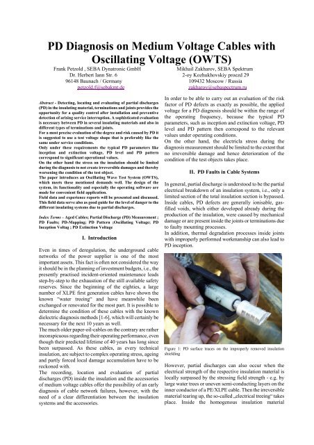
Figure 1: <str<strong>on</strong>g>PD</str<strong>on</strong>g> surface traces <strong>on</strong> the improperly removed insulati<strong>on</strong><br />
shielding<br />
However, partial discharges can also occur when the<br />
electrical strength of the respective insulati<strong>on</strong> material is<br />
locally surpassed by the stressing field strength - e.g. by<br />
large water trees or uneven semi-c<strong>on</strong>ducting layers <strong>on</strong> the<br />
inner c<strong>on</strong>ductor of a PE/XLPE cable. Then the irreversible<br />
material tearing up, the so-called „electrical treeing“ takes<br />
place. Inside the homogenous insulati<strong>on</strong> material
PE/XLPE, electrical trees grow towards the opposite<br />
c<strong>on</strong>ductor with approx. 0.2 mm/h even in the case of<br />
operating field strengths so that a complete breakdown<br />
takes place inside the cable within a few days [6;7].<br />
Figure 2: Electrical tree initiated via voltage test <strong>on</strong> a vented tree<br />
Water trees themselves do not show any partial discharge<br />
so that the <str<strong>on</strong>g>PD</str<strong>on</strong>g> diagnosis is not adequate for the evaluati<strong>on</strong><br />
of the c<strong>on</strong>diti<strong>on</strong> of WT-affected PE/XLPE insulati<strong>on</strong>s. For<br />
this problem, the network operators have adequate<br />
dielectric diagnosis methods available [1-6].<br />
Inside paper insulated cables (PILC) and their accessories,<br />
however, a completely different <str<strong>on</strong>g>PD</str<strong>on</strong>g> behaviour is to<br />
observe.<br />
In the laminated and impregnated paper insulati<strong>on</strong>, <str<strong>on</strong>g>PD</str<strong>on</strong>g><br />
occur locally in dry areas, but they may disappear again<br />
due to the mass migrati<strong>on</strong> in the case of thermal load<br />
changes. In the same way, carb<strong>on</strong>isati<strong>on</strong>s have the effect<br />
of c<strong>on</strong>ductive bridges due to the reacting <str<strong>on</strong>g>PD</str<strong>on</strong>g> so that the<br />
potential differences are “short-circuited“ and the <str<strong>on</strong>g>PD</str<strong>on</strong>g><br />
disc<strong>on</strong>tinued.<br />
Due to the barrier effect of the laminated paper insulati<strong>on</strong>,<br />
the propagati<strong>on</strong> of <str<strong>on</strong>g>PD</str<strong>on</strong>g> channels is largely impeded so that<br />
PILC cables with <str<strong>on</strong>g>PD</str<strong>on</strong>g> in the insulati<strong>on</strong> may be safe for<br />
operati<strong>on</strong> even for many years.<br />
A similar behaviour can be found in oil-filled joints. The<br />
operati<strong>on</strong> of drained terminati<strong>on</strong>s, however, is directly<br />
threatened, because self-healing by a c<strong>on</strong>tinuous flow of<br />
mass or cable oil cannot take place.<br />
From a multitude of <str<strong>on</strong>g>PD</str<strong>on</strong>g> measurements <strong>on</strong> PE/XLPE<br />
cables and PILC cables, there is knowledge and<br />
experience for the evaluati<strong>on</strong> of the threat to the<br />
respective insulati<strong>on</strong> systems by <str<strong>on</strong>g>PD</str<strong>on</strong>g>.<br />
III. Requirements for the On-Site <str<strong>on</strong>g>PD</str<strong>on</strong>g> <str<strong>on</strong>g>Diagnosis</str<strong>on</strong>g><br />
Basically, three parameters are important for the<br />
judgement of the <str<strong>on</strong>g>PD</str<strong>on</strong>g> behaviour of a cable system.<br />
<str<strong>on</strong>g>PD</str<strong>on</strong>g> Incepti<strong>on</strong> <strong>Voltage</strong> Ui : The <str<strong>on</strong>g>PD</str<strong>on</strong>g> incepti<strong>on</strong> voltage is<br />
determined by a stepwise or c<strong>on</strong>tinuous increase of the<br />
voltage applied to the test object. Ui is the voltage, where<br />
measurable <str<strong>on</strong>g>PD</str<strong>on</strong>g> start, i.e., the sensitivity of the measuring<br />
system and the existing ground noise during the<br />
measurement influence the recording of the incepti<strong>on</strong><br />
voltage.<br />
<str<strong>on</strong>g>PD</str<strong>on</strong>g> Extincti<strong>on</strong> <strong>Voltage</strong> Ue : Since <str<strong>on</strong>g>PD</str<strong>on</strong>g> sources often show<br />
a hysteresis resp<strong>on</strong>se regarding the incepti<strong>on</strong> and<br />
extincti<strong>on</strong> voltage, i.e., the <str<strong>on</strong>g>PD</str<strong>on</strong>g> in ignited locati<strong>on</strong>s are<br />
often <strong>on</strong>ly extinguished below the <str<strong>on</strong>g>PD</str<strong>on</strong>g> incepti<strong>on</strong> voltage,<br />
the value of the extincti<strong>on</strong> voltage is important for the<br />
judgment of the risk factor.<br />
<str<strong>on</strong>g>PD</str<strong>on</strong>g> Level : Normally, the maximum impulse charge at Uo<br />
is used as a assessment criteri<strong>on</strong>. There are already<br />
relatively good experiences in order to evaluate the risk<br />
factor for the reliability of operati<strong>on</strong> depending <strong>on</strong> the<br />
locati<strong>on</strong> of the <str<strong>on</strong>g>PD</str<strong>on</strong>g> (cable, joint, terminati<strong>on</strong>s), the type of<br />
insulati<strong>on</strong> of the cable and the design of the accessories.<br />
The occurrence of <str<strong>on</strong>g>PD</str<strong>on</strong>g> impulses also characterizes the risk<br />
coming from a <str<strong>on</strong>g>PD</str<strong>on</strong>g> source.<br />
The phase-resolved display of the <str<strong>on</strong>g>PD</str<strong>on</strong>g> offers for typical<br />
types of <str<strong>on</strong>g>PD</str<strong>on</strong>g> sources the possibility of comparis<strong>on</strong> with socalled<br />
“fingerprints“. For GIS systems, there are already<br />
relatively exact characterizati<strong>on</strong>s. For cable systems,<br />
however, fingerprints depend <strong>on</strong> a number of influencing<br />
factors so that presently significant correlati<strong>on</strong>s are not<br />
possible, but useful additi<strong>on</strong>al informati<strong>on</strong> can<br />
nevertheless be derived.<br />
For the network operator, the following requirements are<br />
important for the assessment of cable systems.<br />
• The cable systems should be free from <str<strong>on</strong>g>PD</str<strong>on</strong>g> at the rated<br />
voltage Uo.<br />
• In networks with res<strong>on</strong>ance earthed starpoint , there<br />
should not be any <str<strong>on</strong>g>PD</str<strong>on</strong>g> up to 1.7 Uo. Should this<br />
nevertheless be the case, the <str<strong>on</strong>g>PD</str<strong>on</strong>g> must be extinguished<br />
again above Uo.<br />
• For the <str<strong>on</strong>g>PD</str<strong>on</strong>g> diagnosis, a voltage shape should be used,<br />
which creates comparable <str<strong>on</strong>g>PD</str<strong>on</strong>g> parameters (incepti<strong>on</strong><br />
and extincti<strong>on</strong> voltage and <str<strong>on</strong>g>PD</str<strong>on</strong>g> level), such as the 50<br />
Hz service voltage.<br />
• The voltage stress during the <str<strong>on</strong>g>PD</str<strong>on</strong>g> diagnosis must<br />
incite the existing <str<strong>on</strong>g>PD</str<strong>on</strong>g> faults in order to detect them,<br />
determine the intensity and locate the positi<strong>on</strong> of the<br />
<str<strong>on</strong>g>PD</str<strong>on</strong>g>.<br />
• The <str<strong>on</strong>g>PD</str<strong>on</strong>g> diagnosis must to take place n<strong>on</strong>destructively,<br />
i.e., no additi<strong>on</strong>al fault locati<strong>on</strong>s in the<br />
form of electrical trees should be initiated.<br />
• When using power-frequency or similar voltage<br />
shapes, the gradual increase in voltage may be limited<br />
to levels up to max. 1.7 Uo during the diagnosis. This<br />
way, the risk of damage to the insulati<strong>on</strong> is<br />
minimized.<br />
• When using distinct different voltage shapes (e.g. 0.1<br />
Hz Sinus), there should be knowledge for<br />
interpretati<strong>on</strong> as to how and whether the obtained test<br />
readings can be transferred to 50 Hz service<br />
c<strong>on</strong>diti<strong>on</strong>s.
<str<strong>on</strong>g>PD</str<strong>on</strong>g> incepti<strong>on</strong> voltage<br />
2.5<br />
Figure 3: Influence of the voltage shape to the electrical tree incepti<strong>on</strong><br />
voltage (tree igniti<strong>on</strong>) [9]<br />
The studies of Kalkner and others [9] in figure 3 show that<br />
in case of oscillating voltages the igniti<strong>on</strong> of electrical<br />
trees and thus the irreversible destructi<strong>on</strong> of the dielectric<br />
at n<strong>on</strong>-homogeneities or water trees <strong>on</strong>ly develops at<br />
distinct higher voltages. Hence this voltage shape stands<br />
out as a particularly „gentle“ voltage stress for a n<strong>on</strong>destructive<br />
<str<strong>on</strong>g>PD</str<strong>on</strong>g> diagnosis<br />
IV. Oscillating Wave Test System (OWTS)<br />
The Oscillating Wave Test System described hereinafter<br />
unites all advantages of a n<strong>on</strong>-destructive <str<strong>on</strong>g>PD</str<strong>on</strong>g> diagnosis<br />
system.<br />
The principle of high voltage generati<strong>on</strong> and the<br />
measuring circuit are shown in figure 4.<br />
V<br />
2<br />
1.5<br />
1<br />
0.5 ~<br />
Needle<br />
wt-damage<br />
50 Hz-<br />
Sinus<br />
1 k<br />
Semic<strong>on</strong> Halbleiter- Inductivity Induktivität 0,7<br />
H<br />
Switch schalter<br />
DC DC IGBT<br />
150 M<br />
Source Quelle<br />
0 ... 36<br />
kV<br />
15 k<br />
t<br />
P<br />
D<br />
t<br />
PC Computer with Display mit<br />
Anz eige and und A/D A/D<br />
c<strong>on</strong>verter Wandler<br />
0.1 Hz-<br />
Cosinus 2<br />
Filter Filter<br />
0.1 Hz-<br />
Sinus<br />
<strong>Voltage</strong><br />
Spannungsteiler<br />
Devider<br />
1 nF<br />
10 µF<br />
Oscillating<br />
voltages<br />
Ankopplung Coupling<br />
s-Vierpol<br />
Device<br />
AKV<br />
PTest<br />
rüfling<br />
Object<br />
Figure 4: Principle circuit diagram of the OWTS – <str<strong>on</strong>g>PD</str<strong>on</strong>g> – diagnosis<br />
system<br />
The test object is charged within a few sec<strong>on</strong>ds to the<br />
desired voltage and then discharged via the electr<strong>on</strong>ic<br />
high-voltage switch and the specially designed air-core<br />
coil. This creates an oscillating decay voltage, the<br />
oscillati<strong>on</strong> frequency of which is determined by the<br />
inductance of the air-core coil and the capacity of the test<br />
object according to equati<strong>on</strong> 1.<br />
<strong>Voltage</strong> shape and <str<strong>on</strong>g>PD</str<strong>on</strong>g> signals<br />
Determinati<strong>on</strong> of tan δ; resoluti<strong>on</strong> 1*E-3<br />
Figure 5: Oscillating testing voltage with <str<strong>on</strong>g>PD</str<strong>on</strong>g> pattern and tan δ<br />
determinati<strong>on</strong><br />
The attenuati<strong>on</strong> of the decaying voltage amplitude<br />
corresp<strong>on</strong>ds to the dielectric losses within the test object,<br />
because the ohmic line losses in the test circuit can be<br />
neglected. This way, the dielectric characteristics (tan δ)<br />
of the test object can be characterized (figure 5).<br />
Oscillati<strong>on</strong> frequency of the testing voltage<br />
f o<br />
1<br />
= (1)<br />
2π<br />
LC<br />
Depending <strong>on</strong> the length of the cable to be tested and its<br />
kilometric capacity, an oscillating switching voltage with a<br />
frequency of 100 Hz up to 1 kHz is generated. For typical<br />
cable lengths of 1000 m, the oscillati<strong>on</strong> frequency is about<br />
250 to 300 Hz, i.e., factor 5 to 6 to the operating<br />
frequency. In order to measure in the low frequency range<br />
below 300 Hz even <strong>on</strong> short cables, an additi<strong>on</strong>al <str<strong>on</strong>g>PD</str<strong>on</strong>g>-free<br />
load capacitor with a blocking inductance can opti<strong>on</strong>ally<br />
be c<strong>on</strong>nected.<br />
The <str<strong>on</strong>g>PD</str<strong>on</strong>g> test circuit is calibrated according to IEC 60270
[10]. By a stepwise increase of the testing voltage, the <str<strong>on</strong>g>PD</str<strong>on</strong>g><br />
incepti<strong>on</strong> voltage Ui is determined. The <str<strong>on</strong>g>PD</str<strong>on</strong>g> extincti<strong>on</strong><br />
voltage can also be clearly determined by the attenuated<br />
voltage curve. An indicati<strong>on</strong> for the type of <str<strong>on</strong>g>PD</str<strong>on</strong>g> source<br />
(void or inclined c<strong>on</strong>tact surface) is often given by the <str<strong>on</strong>g>PD</str<strong>on</strong>g><br />
pattern, i.e. the occurrence and phase angle of the <str<strong>on</strong>g>PD</str<strong>on</strong>g><br />
pulses.<br />
A comfortable software for locating the <str<strong>on</strong>g>PD</str<strong>on</strong>g> sources is<br />
available with which the reflecti<strong>on</strong> patterns of the recorded<br />
and stored <str<strong>on</strong>g>PD</str<strong>on</strong>g> signals are evaluated in a semi- or fully<br />
automatic process (figure 6). By digital filtering, an<br />
excellent interference suppressi<strong>on</strong> is achieved, and the<br />
attenuati<strong>on</strong> of <str<strong>on</strong>g>PD</str<strong>on</strong>g> signals <strong>on</strong> l<strong>on</strong>g cables is taken into<br />
c<strong>on</strong>siderati<strong>on</strong> for the evaluati<strong>on</strong> of the reflecti<strong>on</strong> patterns.<br />
Original form of the <str<strong>on</strong>g>PD</str<strong>on</strong>g> signals<br />
Locati<strong>on</strong> of <str<strong>on</strong>g>PD</str<strong>on</strong>g> fault positi<strong>on</strong>s<br />
with TDR software<br />
Figure 6: <str<strong>on</strong>g>PD</str<strong>on</strong>g> signals with a bandwidth up to 3 MHz and automated<br />
locati<strong>on</strong> of <str<strong>on</strong>g>PD</str<strong>on</strong>g> sources<br />
This enables a successful locati<strong>on</strong> of <str<strong>on</strong>g>PD</str<strong>on</strong>g> sources also <strong>on</strong><br />
PILC cables up to a length of 3-4 km.<br />
As a result of this evaluati<strong>on</strong>, the so-called mapping of the<br />
<str<strong>on</strong>g>PD</str<strong>on</strong>g> sources can be displayed (figure 7). In our case, the<br />
<str<strong>on</strong>g>PD</str<strong>on</strong>g> sources are represented over the cable length for all<br />
three phases of the system. It can clearly be seen that in<br />
the set of joints at 200 m in c<strong>on</strong>ductor 1 and at 360 m in<br />
c<strong>on</strong>ductors 2 and 3, <str<strong>on</strong>g>PD</str<strong>on</strong>g> with high intensity very often<br />
occur. This test object is a 20 kV XLPE cable system with<br />
poorly mounted heat-shrink joints. Remarkably these<br />
extremely high <str<strong>on</strong>g>PD</str<strong>on</strong>g> levels did not lead to a failure of the<br />
joints until 5 to 6 years of operati<strong>on</strong>.<br />
Because of the stochastic of <str<strong>on</strong>g>PD</str<strong>on</strong>g> processes, a statistical<br />
evaluati<strong>on</strong> of the <str<strong>on</strong>g>PD</str<strong>on</strong>g> signals is absolutely necessary for a<br />
significant statement about the type and locati<strong>on</strong> of <str<strong>on</strong>g>PD</str<strong>on</strong>g><br />
sources! Interpretati<strong>on</strong>s based <strong>on</strong> just a few assumed <str<strong>on</strong>g>PD</str<strong>on</strong>g><br />
signals can lead to wr<strong>on</strong>g decisi<strong>on</strong>s with very high<br />
subsequent costs. After all, the network operator must<br />
make a sound decisi<strong>on</strong> about the replacement or not of the<br />
affected accessories or cable secti<strong>on</strong>s based <strong>on</strong> the <str<strong>on</strong>g>PD</str<strong>on</strong>g><br />
diagnosis.<br />
Figure 7: Statistical distributi<strong>on</strong> of the <str<strong>on</strong>g>PD</str<strong>on</strong>g> locati<strong>on</strong>s and <str<strong>on</strong>g>PD</str<strong>on</strong>g> levels over<br />
the cable length of a 20 kV XLPE cable system<br />
V. Knowledge Base and Limiting Values for the <str<strong>on</strong>g>PD</str<strong>on</strong>g><br />
<str<strong>on</strong>g>Diagnosis</str<strong>on</strong>g><br />
Worldwide, there is a multitude of practical experience of<br />
<strong>on</strong>-site <str<strong>on</strong>g>PD</str<strong>on</strong>g> measurements. [10-16]. In the direct<br />
comparis<strong>on</strong> of different <str<strong>on</strong>g>PD</str<strong>on</strong>g> measuring systems, OWTS<br />
was judged to be the best system for the c<strong>on</strong>sidered cases<br />
of applicati<strong>on</strong> [16].<br />
Normally, ground noise levels within the range below 100<br />
pC can be observed in the field so that the requirements<br />
for a sufficient measuring sensitivity are given in order to<br />
detect <str<strong>on</strong>g>PD</str<strong>on</strong>g>.<br />
The occurrence of <str<strong>on</strong>g>PD</str<strong>on</strong>g> signals is str<strong>on</strong>gly determined by<br />
the frequency of the testing voltage and hence the voltage<br />
gradient. In particular regarding <str<strong>on</strong>g>PD</str<strong>on</strong>g> sources in the area of<br />
the field stress c<strong>on</strong>trol (inclined c<strong>on</strong>tact surfaces) in joints<br />
and terminati<strong>on</strong>s, highly frequency-dependent <str<strong>on</strong>g>PD</str<strong>on</strong>g><br />
incepti<strong>on</strong> voltages, impulse occurrences and <str<strong>on</strong>g>PD</str<strong>on</strong>g> levels can<br />
be observed [13;14;16]. Therefore, res<strong>on</strong>ance testing<br />
systems with variable or fixed frequencies and the<br />
oscillating switching voltage (OVS) to simulate the<br />
operating voltage are recommended. The OSV represent<br />
nearly no stress due to their short applicati<strong>on</strong> time (some<br />
100 ms) <strong>on</strong> the test object and do not cause significant<br />
damage during the diagnosis measurement [13-15].<br />
The <str<strong>on</strong>g>PD</str<strong>on</strong>g> locati<strong>on</strong>s are often to be found in the accessories<br />
of the cables. There is comprehensive experience <strong>on</strong> PILC<br />
cables (figure 8).
100%<br />
90%<br />
80%<br />
70%<br />
60%<br />
50%<br />
40%<br />
30%<br />
20%<br />
10%<br />
0%<br />
Figure 8: <str<strong>on</strong>g>PD</str<strong>on</strong>g> incepti<strong>on</strong> voltages and <str<strong>on</strong>g>PD</str<strong>on</strong>g> locati<strong>on</strong>s in PILC cables [14]<br />
Due to the different insulati<strong>on</strong> materials and their<br />
sensitivity for or resistance against <str<strong>on</strong>g>PD</str<strong>on</strong>g>, other criteria have<br />
to applied to PE/XLPE cables than to PILC cables<br />
regarding the risk evaluati<strong>on</strong> of partial discharges (figure<br />
9).<br />
The shown trend or limiting values offer the network<br />
operator a good orientati<strong>on</strong>. Nevertheless, the respective<br />
operating experience with the relevant cable systems is of<br />
great importance.<br />
For instance, a joint in PILC cables can be the cause of<br />
brief transient earth faults even with relatively low <str<strong>on</strong>g>PD</str<strong>on</strong>g><br />
levels. If it is found out during the <str<strong>on</strong>g>PD</str<strong>on</strong>g> diagnosis that <strong>on</strong>ly<br />
this <strong>on</strong>e joint is <str<strong>on</strong>g>PD</str<strong>on</strong>g>-affected, it is obvious to replace this<br />
joint in order to eliminate the problem.<br />
Typical series faults, e.g. due to wr<strong>on</strong>g mounting, will be<br />
assessed according to the outage behaviour and the <str<strong>on</strong>g>PD</str<strong>on</strong>g><br />
parameters, in particular the incepti<strong>on</strong> voltage.<br />
An observati<strong>on</strong> of the tendency at intervals of 3 to 6<br />
m<strong>on</strong>ths is useful in any case, if the limiting values shown<br />
in figure 9 have been reached or exeeded during the <str<strong>on</strong>g>PD</str<strong>on</strong>g><br />
diagnosis, but before an outage of the cable system has<br />
been stated.<br />
Cable Element Type Trend / Limit<br />
Insulati<strong>on</strong><br />
20%<br />
29%<br />
51%<br />
51%<br />
33%<br />
16%<br />
<str<strong>on</strong>g>PD</str<strong>on</strong>g>IV <str<strong>on</strong>g>PD</str<strong>on</strong>g> Lokalisierungen<br />
<str<strong>on</strong>g>PD</str<strong>on</strong>g> Activity up to Uo <str<strong>on</strong>g>PD</str<strong>on</strong>g> Activity up to 1.3Uo<br />
<str<strong>on</strong>g>PD</str<strong>on</strong>g> Activity > 1.3Uo Cable Insulati<strong>on</strong><br />
Cable Terminati<strong>on</strong>s Joints<br />
Paper up to 10.000 pC<br />
PE /XLPE < 20 pC<br />
Oil<br />
Insulati<strong>on</strong><br />
> 10.000 pC<br />
Joints<br />
Oil /Resin<br />
Insulati<strong>on</strong><br />
5.000 pC<br />
Silic<strong>on</strong>e / EPR<br />
Insulati<strong>on</strong><br />
500 to 1.000 pC<br />
Oil<br />
Terminati<strong>on</strong><br />
6.000 pC<br />
Terminati<strong>on</strong>s<br />
dry<br />
Terminati<strong>on</strong><br />
3.500 pC<br />
Shrink-/Slide-<strong>on</strong><br />
Terminati<strong>on</strong>s<br />
250 pC<br />
Figure 9: Trend or limiting values for <str<strong>on</strong>g>PD</str<strong>on</strong>g> levels [14]<br />
It is interesting to evaluate the quality of newly installed<br />
cable systems, in particular when transiti<strong>on</strong> joints<br />
(PILC/XLPE) have been mounted. The mounting quality<br />
of transiti<strong>on</strong> joints is highly influenced by the subjective<br />
factor due to the complexity of the processes.<br />
The <str<strong>on</strong>g>PD</str<strong>on</strong>g> diagnosis enables the selective evaluati<strong>on</strong> of the<br />
joint as well as of the paper and XLPE cable secti<strong>on</strong>s<br />
(figure 10). Besides the c<strong>on</strong>centrated <str<strong>on</strong>g>PD</str<strong>on</strong>g> activity in the<br />
transiti<strong>on</strong> joint, locally distributed <str<strong>on</strong>g>PD</str<strong>on</strong>g> can be observed in<br />
the paper cable secti<strong>on</strong>.<br />
The quality c<strong>on</strong>trol of cable installati<strong>on</strong>s by <str<strong>on</strong>g>PD</str<strong>on</strong>g><br />
measurements will become increasingly important in the<br />
future, because the increasing cost pressure up<strong>on</strong> the<br />
network operators leads to a placing of the order to the<br />
cheapest c<strong>on</strong>structi<strong>on</strong> company and it is advisable to check<br />
the work performance.<br />
For the evaluati<strong>on</strong> of <str<strong>on</strong>g>PD</str<strong>on</strong>g> occurrences, the <str<strong>on</strong>g>PD</str<strong>on</strong>g> incepti<strong>on</strong><br />
and extincti<strong>on</strong> voltages and the local c<strong>on</strong>centrati<strong>on</strong> of <str<strong>on</strong>g>PD</str<strong>on</strong>g><br />
have to be c<strong>on</strong>sidered as the most important parameters<br />
besides the trend or limiting values of the <str<strong>on</strong>g>PD</str<strong>on</strong>g> levels.<br />
<str<strong>on</strong>g>PD</str<strong>on</strong>g> pattern of a transiti<strong>on</strong> joint<br />
<str<strong>on</strong>g>PD</str<strong>on</strong>g>-Mapping of mixed cable XLPE / PILC<br />
Figure 10: <str<strong>on</strong>g>PD</str<strong>on</strong>g> parameters of a mixed cable secti<strong>on</strong> with oil filled<br />
transiti<strong>on</strong> joint<br />
The decisi<strong>on</strong> path has been summarized <strong>on</strong>ce more in<br />
figure 11.
<str<strong>on</strong>g>PD</str<strong>on</strong>g>IV and<br />
<str<strong>on</strong>g>PD</str<strong>on</strong>g>EV<br />
< Uo<br />
Yes<br />
<str<strong>on</strong>g>PD</str<strong>on</strong>g> in<br />
fittings ?<br />
Yes<br />
<str<strong>on</strong>g>PD</str<strong>on</strong>g> level ><br />
typical ?<br />
Yes<br />
not OK<br />
No<br />
No c<strong>on</strong>centrated<br />
No<br />
<str<strong>on</strong>g>PD</str<strong>on</strong>g> locati<strong>on</strong>s ? fittings ?<br />
Yes<br />
Yes<br />
No<br />
Yes Yes<br />
No No<br />
critical <str<strong>on</strong>g>PD</str<strong>on</strong>g><br />
intensity /<br />
level ?<br />
No Yes<br />
No<br />
Trend<br />
<str<strong>on</strong>g>PD</str<strong>on</strong>g> in<br />
critical <str<strong>on</strong>g>PD</str<strong>on</strong>g><br />
intensity /<br />
level ?<br />
c<strong>on</strong>centrated<br />
<str<strong>on</strong>g>PD</str<strong>on</strong>g> locati<strong>on</strong>s ?<br />
<str<strong>on</strong>g>PD</str<strong>on</strong>g> level <<br />
typical ?<br />
Figure 11 : Decisi<strong>on</strong> process for the classificati<strong>on</strong> of results of the <str<strong>on</strong>g>PD</str<strong>on</strong>g><br />
diagnosis [14]<br />
VI. C<strong>on</strong>clusi<strong>on</strong>s<br />
For the c<strong>on</strong>trol and maintenance of the reliability of<br />
medium voltage cable networks, the <str<strong>on</strong>g>PD</str<strong>on</strong>g> diagnosis is an<br />
important tool for the asset management.<br />
IPC with integrated <str<strong>on</strong>g>PD</str<strong>on</strong>g> Measuring System<br />
and HV -Source<br />
HV - Inductivity and <str<strong>on</strong>g>PD</str<strong>on</strong>g>-free c<strong>on</strong>necti<strong>on</strong> cable<br />
Figure 12 : OWTS installed in the cable test van<br />
Yes<br />
OK<br />
No<br />
The essential characteristics of the Oscillating Wave Test<br />
System with absolutely user-friendly software are :<br />
� Based <strong>on</strong> the res<strong>on</strong>ance principle, the<br />
measuring system produces a sinusoidal<br />
oscillating voltage (compact dimensi<strong>on</strong>s and<br />
low weight)<br />
� The oscillati<strong>on</strong> frequency of the test voltage<br />
amounts to 50 Hz up to several 100 Hz<br />
depending <strong>on</strong> the test object capacity<br />
� The test voltage at the test object corresp<strong>on</strong>ds<br />
largely to the c<strong>on</strong>diti<strong>on</strong>s at operating frequency<br />
� The oscillating voltage is applied to the test<br />
object <strong>on</strong>ly for a few 100 ms<br />
and therefore causes no further ageing or<br />
damage<br />
� The <str<strong>on</strong>g>PD</str<strong>on</strong>g> extincti<strong>on</strong> voltage can be determined<br />
very easily based <strong>on</strong> the<br />
decaying voltage amplitude<br />
� <str<strong>on</strong>g>PD</str<strong>on</strong>g> level measurement according to IEC 60270<br />
at a bandwidth of 150 … 650 kHz<br />
� <str<strong>on</strong>g>PD</str<strong>on</strong>g> source locati<strong>on</strong> at a bandwidth up to 3<br />
MHz with semi- or fully automatic software<br />
Statements <strong>on</strong> the remaining life time of cables are<br />
generally not possible via the <str<strong>on</strong>g>PD</str<strong>on</strong>g> diagnosis. However, an<br />
evaluati<strong>on</strong> based <strong>on</strong> practical experience permit an<br />
orientati<strong>on</strong> regarding the c<strong>on</strong>diti<strong>on</strong> and risk factor of the<br />
cable network. This way, the <str<strong>on</strong>g>PD</str<strong>on</strong>g> diagnosis gives valuable<br />
informati<strong>on</strong> for necessary maintenance activities, if<br />
necessary, and helps to use the available budgets<br />
effectively.<br />
VII. References<br />
[1]Hoff, G.; Optimierung und Grenzen der technischen Diagnostik am<br />
Beispiel der Alterungsbestimmung polymerisolierter<br />
Mittelspannungskabel, Dissertati<strong>on</strong>, BUGH Wuppertal, 2003.<br />
[2] Hoff,G.; Kranz, H.-G.; Beigert, M.; Petzold, F.;Kneissl, Ch.;<br />
Zustandsorientierte Instandhaltung eines Polymerisolierten 20-KV<br />
Kabelnetzes mit der IRC-Analyse, EW Jg. 100 (2001), Heft 22.<br />
[3] Hvidsten,S.; Faremo, H.; Benjaminsen,J.-T.; Ildstad, E.; C<strong>on</strong>diti<strong>on</strong><br />
assessment of water treed service aged XLPE cables by dielectric<br />
resp<strong>on</strong>se measurements, Cigre Sessi<strong>on</strong>, Paris, 2000.<br />
[4] Patsch, R.; Romero, P.; Verlustfaktormessungen bei<br />
unterschiedlichen Frequenzen als Diagnoseverfahren water tree<br />
geschädigter Isolierungen, 40IWK, Ilmenau, 1995.<br />
[5] G. Hoff, H.-G. Kranz: Correlati<strong>on</strong> Between Return <strong>Voltage</strong> and<br />
Relaxati<strong>on</strong> Current Measurements <strong>on</strong> XLPE <strong>Medium</strong> <strong>Voltage</strong> <strong>Cables</strong>,<br />
ISH 1999, L<strong>on</strong>d<strong>on</strong>, UK, paper 5.102. S14.<br />
[6] R.Plath,W.Kalkner,I.Krage; Vergleich v<strong>on</strong> Diagnosesystemen zur<br />
Beurteilung des Alterungszustandes PE/VPE-isolierter<br />
Mittelspannungskabel<br />
Elektrizitätswirtschaft J.96 (1997)<br />
[7]E. Neudert, M. Sturm: Characterizati<strong>on</strong> of tree processes in XLPE by<br />
<str<strong>on</strong>g>PD</str<strong>on</strong>g> Measurement at 50 Hz and very low frequencies, ICDI Budapest,<br />
1997.<br />
[8] R. Bach, W. Kalkner, H. Oldehoff: Spannungsprüfungen zur<br />
Beurteilung v<strong>on</strong> Mittelspannungskabelanlagen, Elektrizitätswirtschaft,<br />
Jg(92), 1993, Heft 17/18, S. 1068 ff.<br />
[9] W.Kalkner;R.Bach; Comparative study <strong>on</strong> alternative test voltages<br />
for layed medium voltage cables; ISH 91 Dresden, August 1991<br />
[10] Partial Discharge Measurements. IEC 60270, Third Editi<strong>on</strong> 1998-06
[11] E.Pultrum;E.Hetzel; VLF Discharge Detecti<strong>on</strong> as a Diagnostic Tool<br />
for MV <strong>Cables</strong>; IEEE PES Summer meeting July 1995;Berlin<br />
[12] J.T.Holboll, H Edin; <str<strong>on</strong>g>PD</str<strong>on</strong>g> Detecti<strong>on</strong> vs. Loss Measurements at High<br />
<strong>Voltage</strong>s with Variable Frequencies ; 10 th Int. Symposium <strong>on</strong> HV<br />
Engineering, M<strong>on</strong>treal Canada, 1997<br />
[13] E.Gulski,J.J.Smit,P.N.Seitz;<str<strong>on</strong>g>PD</str<strong>on</strong>g> Measurements On-site using<br />
Oscillating Wave test System, IEEE Internati<strong>on</strong>al Symposium <strong>on</strong> EI,<br />
Washingt<strong>on</strong> DC ,USA June 1998<br />
[14] F.J.Wester;E.Gulski;J.J.Smit;P.N.Seitz; Experiences from On-site<br />
<str<strong>on</strong>g>PD</str<strong>on</strong>g> Measurements using Oscillating Wave Test System; ISH 99 L<strong>on</strong>d<strong>on</strong><br />
August 1999<br />
[15] E.Gulski,J.J.Smit,P.N.SeitzR.F.F.K<strong>on</strong>ing;M.Turner ; On-site <str<strong>on</strong>g>PD</str<strong>on</strong>g><br />
diagnostics of medium power cables, Jicabel 99; Paris June 1999<br />
[16] V.Colloca,A.Fara, M.d.Nigris,G.Rizzi; Comparis<strong>on</strong> am<strong>on</strong>g different<br />
diagnostic sytems for medium voltage cable lines ; Paper CIRED 2001<br />
Paris<br />
Frank Petzold was born 1955 in Dresden (Germany).<br />
From 1975 to 1979 he studied electrical engineering at the High <strong>Voltage</strong><br />
Institute of the Technical University Dresden. In 1984 graduati<strong>on</strong> of<br />
doctors degree at the High <strong>Voltage</strong> Institute Technical University<br />
Dresden. Dissertati<strong>on</strong> ”Influence of several stabilizers <strong>on</strong> tree-incepti<strong>on</strong><br />
in XLPE insulati<strong>on</strong>s”<br />
From 1984 to 1990 he was chief of the development department in the<br />
cable factory KWO Schwerin (Germany).<br />
In the time from 1990 to 1999 he worked as self employer with his own<br />
c<strong>on</strong>sulting company for cable fault locati<strong>on</strong> and leak detectio.<br />
Since 2000 he is Technical Director of SEBA Dynatr<strong>on</strong>ic GmbH<br />
Germany , resp<strong>on</strong>sible for R&D and technical marketing.<br />
Mr. Petzold is Member of several working groups in IEC; CIGRE and<br />
IEEE.