
Create successful ePaper yourself
Turn your PDF publications into a flip-book with our unique Google optimized e-Paper software.
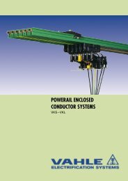
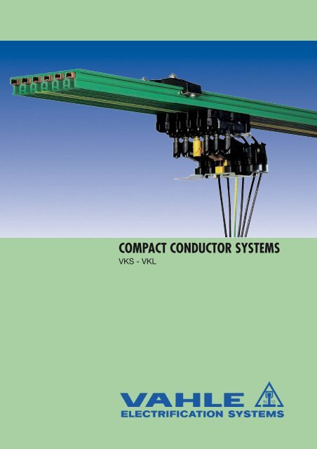
COMPACT CONDUCTOR SYSTEMS<strong>VKS</strong> - <strong>VKL</strong>
POWERAILS <strong>VKS</strong> & <strong>VKL</strong>INDEX <strong>VKS</strong> <strong>VKL</strong>Basic description 3, 4 3, 4Layout planning 5 5Engineering data, Powerail standard sections 6, 7 22Powerail curves 8 22Jointing material 8 23Hangers 9 23End caps 9 23Feeds 10, 11 24Transfer guides 12 –Transfer funnels 13, 14 –Expansion sections 14 –Sectionalizing 15 23Current collectors 15, 17 24Compact collectors 15 - 17 –Accessories and spares for collectors 18 - 23 24KTW-Systems 24 24Standard brackets 25 25Snap-on brackets 25 25<strong>VKS</strong>-system, 7 pole for HRL 26 –Examples for ordering 27, 28 27Questionnaire (1) 29 29Production program 32 32Collector rings <strong>VKS</strong> (see leaflet No. 102 s) – –Electrical Properties: <strong>VKS</strong> <strong>VKL</strong>Ampacity: = 140 A (3) 30 AAllowed voltage = 690 V (4) 400 VElectrical strength according toDIN 53481= >25 kV/mmSpecial electricel strength according toIEC 60093= 1 x 10 16 Ohmx cmSurface resistance according to IEC 60093 = 2,1 x 10 15 OhmCreep resistance accordingto IEC 60112 = CTI > 400Flame test proof per DIN 4102 part 1, class B1,no flaming particles, self extinguishingChemical resistance of the isolating profile at + 45°C ambienttemperatureBenzine, petroleum, fatsresistantCaustic soda upto 50%resistantHydrochloric acid, concentratedresistantSulfuric acid upto 50%resistantWater absorption: max. at 100 °C = 1%max. at 20 °C = 0,06%Temperature resistance:from -20 °C (2) upto + 55 °C with a rail length upto 4 mfrom 0° C (2) upto +40 °C with a rail length > 4 mConductor copper unitCross sectiont 16 25 30 35 mm 2Impedance1,107 0,730 0,603 0,520Ohm/at 50 Hz1000 mOhm/Resistance 1,102 0,723 0,595 0,5101000 mMechanical properties:Flexible strength = 74-85 N/mm 2Tensile strength = 44-55 N/mm 2Please consult factory for galvanizing plants, picklinglines, other aggressive or deep freeze ambients, aswell as low voltage and data transmission applications,indicating special environmental conditions.To speed up quotations and order processing, wewould appreciate receiving your drawings or sketchesfor powerail systems with curves, dead sections,turntables, switches, etc.Please use our questionnaire, page 29 and 30.2(1)Please enclose the Questionnaire to your inguiry.(2)Consult factory for use below 0° C (32° F) [deep freeze housing].(3)80 % ED(4)Not with UL-approval; U UL = 600 V
POWERAILS <strong>VKS</strong> & <strong>VKL</strong><strong>VAHLE</strong> Powerails <strong>VKS</strong> and <strong>VKL</strong> are space saving conductorsystems, designed to prevent any accidental contact and hazardto personnel and are test finger proof to regulations VDE 0470,part 1 (EN 60529), protection code IP 21.Collectors are proof against accidental touch only when fullyentered into powerail.Powerail installations within reach of hand require a special protectionon the part of operator against accidental touch of currentcollectors which are leaving the powerail (e.g. locking or cut-offthe power).This is applicable for voltages above 25 V AC respectively 60 V DC.The creeping distance between the conductors of the <strong>VKS</strong>-conductoris 30 mm.The different plastic housings hold from 3 to 6 copper or stainlesssteel conductors. Multiple conductor systems can be easilydesigned by combining several plastic housings.The minimal space required allows the systems to be integratedin the crane or hoist track or in other special runway profiles.The minimal required space allows a direct layout in rail tracks orspecial track profiles.The <strong>VKS</strong> & <strong>VKL</strong> Powerail can be used for indoor and roof-over(rain protected) applications. They can be installed with lateral orsuspended mounting and straight or curved tracks are available.Approvals (<strong>VKS</strong>):UL-approval.<strong>VKS</strong> Powerail Systemsare designed for safe mobile power feeding of:Hoists, Monorail Systems, Stacker Cranes, Machine Tools, Productionand Testing Lines, also for Sliding Switches, Turntables,Hoisting Stations, Transfers, and many other Applications, incl.Data and Signal Transmission.HousingThe well insulating plastic housing holds 3-6 conductors. 4 and6 m standard lengths and shorter sections to coincide with yourrunway requirements are available. The asymmetrical housingavoids phase reversing. The ground conductor is identified by theinternational yellow colour coding.Joints:The plastic sections are connected with plastic joint caps, theconductors with spring-loaded copper connectors.Feed Sets:End feeds or line feeds with terminal boxes are available, also lowmounting line feeds for cable connection. Line feeds comefactory assembled on 1 m long Powerail sections. End feedscome unassembled without any Powerail section.Hangers:All sections are to be fixed from at least 1 hanger and themaximum permissible support centres of 1 m (with doublecollectors 0.8 m) must be adhered to (see page 5). The hangersare equippedwith M 6 bolts & hardware and can be mounted directly to hangerbrackets, monorail tracks or special runway profiles.The Powerail sections are snapped into the hangers. Slidinghangers allow free movement of the Powerail to compensate fortemperature variations. Fixpoint hangers with tapping screw fromanchor points (see installation procedure).For this we have to consider a max. distance of 4 m between2 fixpoints.Standard Support Brackets:Support brackets for easy installation are available, (see page 25).Collectors:The collectors have a continuous rating of 20 A up to 120 A. Onecollector is required for each phase and earth conductor. Theground collectors have a yellow colour and different attachmentsto avoid interchangeability with phase collectors.The collectors have spring loaded carbon brushes for a constantpositive contact with the conductors.Collectors are to be mounted onto towing plates or are to beattached to the moving equipment by means of towing bracketstype UM. Systems with transfers, switches, turntables, etc.require 2 single collectors or one double collector per conductor.The length of the collector cable may not exceed 3 m if the addedovercurrent protection device is not designed for the loadcapacity of this cable. Please refer also to regulations VDE 0100,part 430 and EN 60204-32.(Note: this might happen in case of several collectors running inone system).The provided connecting cables are sufficient for the stated nominalcurrents. For the different laying procedures the reductionsfactors according to DIN VDE 0298-4 have to be considered.Conductor Dead Sections:Conductor dead sections are electrical interrupts of the conductor.Under normal operating conditions a cross over withcollectors to switch the voltage off or on is only allowed with lowpower ratings (control current).Conductor dead sections can be mounted at any position of thesystem. The plastic inserts are pushed into the copper profilesand ensure a smooth transfer of the collector brushes.The length of isolating section has to consider the total length ofcarbon brush and whether carbon brush must or must not bridgethe isolating area.Special attention is required for double collectors or collectorsswitched in parallel. Use double isolating sections wherenecessary.Selection of conductorsin accordance to ampere load and environmental conditions:<strong>VKS</strong> …/ 60 copper conductor for power and control system and data transmission…/100 copper conductor for power and control system…/120 copper conductor for power and control system…/140 copper conductor for power and control systemSeveral combinations of cross sections are possible for one conductor type.3
POWERAILS <strong>VKS</strong> & <strong>VKL</strong><strong>VKL</strong> Powerail Systemsare designed for small current loads and serve for the powersupply of light cranes and for control current systems. The<strong>VKL</strong> Powerail can also be used for Hoists, Jib Cranes, PowerTools, Machine Tools, electrically operated Gates, TestingLines, and other Applications.Housing:The plastic housing holds up to 5 conductors. The groundconductor is identified by international yellow colour code. 4 mstandard lengths and shorter sections to coincide with yourrunway requirements are available.The straight sections are restricted as follows:1.Max. system length: L=100 m2.From the curve to system end: max. L = 50 m3.Between 2 cruves: max. L = 15 mCouplings:The mechanical jointing of the Powerail housing is done by meansof a two-piece plastic joint cap. The conductors get spring-loadedcopper connectors.The ends of each section are milled in to provide the requiredcreepage distance. End caps, fixed with screws, can be installedto every section.Feed TerminalsEnd feeds and line feeds with terminal boxes are available. Theyare factory assembled on 1 m Powerail sections.Feeds:The feeds are available as end or line feeds. They are mounted ona 1 m section.Supports:All sections must be fixed at min. 2 points, at which themaximum support distance of 1000 mm must be kept. Thesupport hanger consists of a pvc part with a fixing screw and is arrangedas a sliding hanger. The fixpoint in the middle of thesystem consists of a hanger with a locating clamp on each side ofthe hanger.Brackets:To support the conductor rail to the crane track mountingbrackets available (see page 25).Collectors:The glider type collectors are guided at thePVC housing. They are supplied with 1 mlong connecting cable. Longer cables areavailable upon request. The carbon brusheshave a continuous current capacity of10 A (15 A at 60 % intermittent duty).Use two collectors for higher ratings. Thetowing arm is the mechanical flexibleconnection between collector and movingequipment.The length of the collector cable should notexeed 3 m if the installed fuse is not suitablefor the cross section of this connectingcable. (Please note: This is often the fact ifmore than one collector is used in the system)Safety advice It must be ensured that thearrangement of the conductor systemprovides minimum distances (0.5 m)between fixed and mobile plant parts (i.e.Between conductor rails, collector trolleysand towing arms) so as to avoid the risk ofpinching.Dead sections:Dead sections for control lines can beinstalled according to your instructions.Electronic layout support:Please use our electronic layoutsoftware.4
LAYOUT PLANNING FOR <strong>VKS</strong> & <strong>VKL</strong>1. SchemeL 4LL 5L 3L 2L 115Endkappe end capVerbindungsmaterial joint SVN/LVStreckeneinsp. line feed VLS/VLE VLS/VLE SVN/LVsliding Gleit- bzw. or Überleitungsstücketransfer guidesStreckeneinspeisung line feed VNS/VNK VNS/VNKKopfeinspeisung end feed VEKS/VEKfixpoint FestaufhängungenhangersL = powerail section (1 m, 2 m, 3 m, 4 m or cut to suit the system)L1 = support spacing for straight runs max. 1 mfor curved runs max. 0,5 mL2 = extending length (max. 200 mm)L3 = air gap for transfers, e. g. switches anddropout sections (3 - 5 mm)L4 = space to remove feed box cover, if applicableL5 = clearance for expansion of powerail (min. 50 mm for <strong>VKS</strong>; 150 mm for <strong>VKL</strong>).2. Symbols in layout plansTrackPowerailJoint materialJoint materialFixpoint hangerSliding hangerEnd capEnd feed,powerEnd feed,control<strong>VKS</strong> <strong>VKL</strong>– –<strong>VKS</strong> <strong>VKL</strong>SVN –– LVVEPS VEPVAS VAVES VEVEKS VEKVEKS VEKLine feed,powerLine feed,controlLine feed,power and controlTransfer guide, straightTransfer guide, obliqueTransfer funnelExpansion sectionIsolating assembly<strong>VKS</strong> <strong>VKL</strong>VNS VNKVNS VNKVLS VLEVU –VUS –VEM –D<strong>VKS</strong> –VSTS VST3. Max. Support spacingType for straight for curvedrunsruns<strong>VKS</strong> 1000 mm 500 mmat KSTU 30, 55 (photo 1) 800 mm 400 mm<strong>VKL</strong> 1000 mm 500 mmApicture 1A < 300 mm Support spacing 0,8 mA > 300 mm Support spacing 1,0 m5
ENGINEERING DATA <strong>VKS</strong>Straight sectionsStandard length 4 and 6 m. (5)(3)6webAttention: Joint material to be ordered separately (see page 8).LHRHNumber Continuous Nominal Voltage drop Minimum Conductor Cross Section (4)Type of Ampere voltage (5) per 100 m Clearence mm 2con- Rating at full ratingductors A V V mm NL / 1,2 PE / 3at 35 °C<strong>VKS</strong> 3/ 60 HS 3 60 690 11,5 7 2x16 1x16<strong>VKS</strong> 3/ 60 SS 3 60 690 11,5 7 2x16 1x16<strong>VKS</strong> 3/100 HS 3 100 690 12,6 7 2x25 1x25<strong>VKS</strong> 3/100 SS 3 100 690 12,6 7 2x25 1x25<strong>VKS</strong> 3/120 HS 3 120 690 12,5 7 2x30 1x30<strong>VKS</strong> 3/120 SS 3 120 690 12,5 7 2x30 1x30<strong>VKS</strong> 3/140 HS 3 140 (2) 690 11,3 7 2x35 1x35<strong>VKS</strong> 3/140 SS 3 140 (2) 690 11,3 7 2x35 1x35Straight sectionsStandard length 4 and 6 m. (5)(3)6web StegAttention: Joint material to be ordered separately (see page 8).LHRHNumber Continuous Nominal Voltage drop Minimum Conductor Cross Section (4)Type of Ampere voltage (5) per 100 m Clearence mm 2con- Rating at full ratingductors A V V mm L1-L3 / 1-3 PE / 4at 35 °C<strong>VKS</strong> 4/ 60 HS 4 60 690 11,5 7 3x16 1x16<strong>VKS</strong> 4/ 60 SS 4 60 690 11,5 7 3x16 1x16<strong>VKS</strong> 4/100 HS 4 100 690 12,6 7 3x25 1x16<strong>VKS</strong> 4/100 SS 4 100 690 12,6 7 3x25 1x16<strong>VKS</strong> 4/120 HS 4 120 690 12,5 7 3x30 1x16<strong>VKS</strong> 4/120 SS 4 120 690 12,5 7 3x30 1x16<strong>VKS</strong> 4/140 HS 4 140 (2) 690 11,3 7 3x35 1x16<strong>VKS</strong> 4/140 SS 4 140 (2) 690 11,3 7 3x35 1x16Straight sectionsStandard length 4 and 6 m. (5)(3)6web StegAttention: Joint material to be ordered separately (see page 8).LHRHNumber Continuous Nominal Voltage drop Minimum Conductor Cross Section (4)Type of Ampere voltage (5) per 100 m Clearence mm 2con- Rating at full ratingductors A V V mm L1-L3 / 1-3 PE 7 4 1,2 / 5,6at 35 °C<strong>VKS</strong> 5/ 60 HS (1) 5 60 690 11,5 7 3x16 1x16 1x16<strong>VKS</strong> 5/ 60 SS (1) 5 60 690 11,5 7 3x16 1x16 1x16<strong>VKS</strong> 5/100 HS (1) 5 100 690 12,6 7 3x25 1x16 1x16<strong>VKS</strong> 5/100 SS (1) 5 100 690 12,6 7 3x25 1x16 1x16<strong>VKS</strong> 5/120 HS (1) 5 120 690 12,5 7 3x30 1x16 1x16<strong>VKS</strong> 5/120 SS (1) 5 120 690 12,5 7 3x30 1x16 1x16<strong>VKS</strong> 5/140 HS (1) 5 140 (2) 690 11,3 7 3x35 1x16 1x16<strong>VKS</strong> 5/140 SS (1) 5 140 (2) 690 11,3 7 3x35 1x16 1x16<strong>VKS</strong> 6/ 60 HS 6 60 690 11,5 7 3x16 1x16 2x16<strong>VKS</strong> 6/ 60 SS 6 60 690 11,5 7 3x16 1x16 2x16<strong>VKS</strong> 6/100 HS 6 100 690 12,6 7 3x25 1x16 2x16<strong>VKS</strong> 6/100 SS 6 100 690 12,6 7 3x25 1x16 2x16<strong>VKS</strong> 6/120 HS 6 120 690 12,5 7 3x30 1x16 2x16<strong>VKS</strong> 6/120 SS 6 120 690 12,5 7 3x30 1x16 2x16<strong>VKS</strong> 6/140 HS 6 140 (2) 690 11,3 7 3x35 1x16 2x16<strong>VKS</strong> 6/140 SS 6 140 (2) 690 11,3 7 3x35 1x16 2x166(1)<strong>VKS</strong> 5 eliminates conductor number 6; plastic housing however identical to <strong>VKS</strong> 6.(2)80% ED(3)Section is superseded at 20° C UT.(4)Same cross section at PE (ground) when used for control line. Other conductor combinations are possible.(5)Not with UL-approval; U UL = 600 V
STANDARD-SECTIONS <strong>VKS</strong>5HSwith PESS PEwithout PEConductor Weight Order-No.Materialkg/m726230,5M 631,5max. 10181815 21,5Installation: Installation. lateralPE 3NL72112,5Cu 1,221 153 89•Cu 1,221 153 94•Cu 1,454 153 90•Cu 1,454 153 95•Cu 1,589 153 91•Cu 1,589 153 96•Cu 1,724 154 96•Cu 1,724 156 08•1521,5max. 1018 18L N PE1 2 3 24Installation: horizontalConductor Weight Order-No.Materialkg/mInstallation: lateralCu 1,459 153 99•Cu 1,459 154 04•Cu 1,693 154 00•Cu 1,693 154 05•Cu 1,828 154 01•Cu 1,828 154 06•Cu 1,956 154 31•Cu 1,956 156 54•Installation: horizontal5Conductor Weight Order-No.Materialkg/mCu 2,058 154 09•Cu 2,058 154 14•Cu 2,292 154 10•Cu 2,292 154 15•Cu 2,427 154 11•Cu 2,427 154 16•Cu 2,549 154 87•Cu 2,549 156 55•Cu 2,202 154 19•Cu 2,202 154 24•Cu 2,436 154 20•Cu 2,436 154 25•Cu 2,571 154 21•Cu 2,571 154 26•Cu 2,693 152 60•Cu 2,693 156 56•12611650 3424M6ma x. 1015 21,518 18 18 18 18Anordnung:Installation: lateralseitlich21PEL3L2L17M6max. 1018 18 18 18 18L1 L2 L3 PE 1 21 2 3 4 5 6Anordnung: hängendInstallation: horizontalMarking refers to control lines.12,56543211521,5(5)For supply lengths above 4 m refer to restricted ambient temperature (page 2).•For full type designation add length suffix of Powerail Section, e. g. <strong>VKS</strong> 4/120-2 HS for Order-No. 154 012. Other sections to coincide withyour runway requirements are made up from the next larger straight length.7
COMPONENTS <strong>VKS</strong>Curved sections (1)per your layout drawingmax. L = 3.6 m, support spacing ~ 500 mm, max. angle 180°Joint MaterialRHorizontal curve, R. H. = web outsideHorizontal curve, L. H. = web inside (not shown)Inside curve: RwebOutside curve: R10015webInside curve, lateral = conductor insideOutside curve, lateral = conductor outside (not shown)RmmSurchargeOrder-No.<strong>VKS</strong> 3Horizontal curve, R. H. 400 – 900 150 385Horizontal curve, L. H. 400 – 900 150 386Horizontal curve, R. H. > 900 153 120Horizontal curve, L. H. > 900 153 130Inside curve, lateral 200 – 800 150 387Inside curve, lateral > 800 153 040Outside curve, lateral 200 – 800 150 388Outside curve, lateral > 800 153 050Type Poles Weight kg Order-No.SVN 3/ 10 - 100 3 0,112 156 533SVN 3/120 - 140 3 0,112 156 534Curved sections (1)per your layout drawingmax. L = 3,60 m, support spacing ~ 500 mm, max. angle 180°Joint MaterialConfiguration as shown aboveRmmSurchargeOrder-No.<strong>VKS</strong> 4Horizontal curve, R. H. 400 – 900 150 389Horizontal curve, L. H. 400 – 900 150 391Horizontal curve, R. H. > 900 153 717Horizontal curve, L. H. > 900 150 110Inside curve, lateral 200 – 800 150 392Inside curve, lateral > 800 153 718Outside curve, lateral 200 – 800 150 393Outside curve, lateral > 800 150 100Type Poles Weight kg Order-No.SVN 4/ 10 - 100 4 0,136 156 535SVN 4/120 - 140 4 0,136 156 536Curved sections (1)per your layout drawingmax. L = 3,60 m, support spacing ~ 500 mm, max. angle 180°Configuration as shown aboveJoint Material10015RmmSurchargeOrder-No.<strong>VKS</strong> 5SurchargeOrder-No.<strong>VKS</strong> 6Horizontal curve, R. H. 400 – 900 150 394 150 398Horizontal curve, L. H. 400 – 900 150 395 150 399Horizontal curve, R. H. > 900 153 719 153 721Horizontal curve, L. H. > 900 152 090 152 110Inside curve, lateral 200 – 800 150 396 150 401Inside curve, lateral > 800 153 720 153 722Outside curve, lateral 200 – 800 150 397 150 402Outside curve, lateral > 800 152 080 152 100Type Poles Weight kg Order-No.SVN 5/ 10 - 100 5 0,180 156 537SVN 5/120 - 140 5 0,180 156 538SVN 6/ 10 - 100 6 0,194 156 539SVN 6/120 - 140 6 0,194 156 5408(1)Curved sections will be factory prepared with a 100 mm straight section on both ends. Horizontal curves with more than 90 degreesshould be divided in two or more sections.
COMPENENTS <strong>VKS</strong>Fixpoint hanger (1)with tapping screw & clampSliding hanger (1) End cap (2)suitable L. H. and R. H.15 20M 61520M64813length of powerail30tappingscrew & clamp30Type Weight kg Order-No.VEPS 3 0,042 153 070Type Weight kg Order-No.VAS 3 0,036 153 060Type Weight kg Order-No.VES 3 - L 0,033 153 080VES 3 - M 0,033 152 023Fixpoint hanger (1)with tapping screw & clampSliding hanger 1) End cap (2)suitable L. H. and R. H.M615 20M615204813length of powerail30tappingscrew & clamp30Type Weight kg Order-No.VEPS 4 0,046 150 120Type Weight kg Order-No.VAS 4 0,040 150 130Type Weight kg Order-No.VES 4 - L 0,039 150 140VES 4 - M 0,039 152 022Fixpoint hanger (1)with tapping screw & clampSliding hanger (1) End cap (2)suitable L. H. and R. H.50M6M64813length of powerail15 2015 2030tappingscrew & clamp30Type Weight kg Order-No.Type Weight kg Bestell-NrVEPS 6 0,062 152 120.VAS 6 0,056 152 130Type Weight kg Order-No.VES 6 - L 0,051 152 140VES 6 - M 0,051 152 021(1)Complete with hardware (bolts, nuts, spring washers). Support spacing see page 5.(2)L = loose; c/w hardwareM= Factory assembled9
COMPONENTS <strong>VKS</strong>End feed (1)Terminal box with terminal clamps10015013Section190Type Cable gland (2) Ampacity A Weight kg Order-No.AVEKS 3/10 - 120 L ST-M 40 x 1,5 10 - 120 1,150 156 422Surcharge for assembling 156 423End feed (1)Terminal box with terminal clamps10015013Section190Type Cable gland (2) Ampacity A Weight kg Order-No.AVEKS 4/10 - 120 L ST-M 40 x 1,5 10 - 120 1,230 156 421Surcharge for assembling 156 423End feed (1)Terminal box with terminal clamps10015013Section190Type Cable gland (2) Ampacity A Weight kg Order-No.AVEKS 5/10 - 120 L ST-M 40 x 1,5 10 - 120 1,380 156 420ST-M 20 x 1,5VEKS 6/10 - 120 L ST-M 40 x 1,5 10 - 120 1,460 156 419ST-M 20 x 1,5Surcharge for assembling 156 42310(1)End feeds loose as components. Sections are to be ordered separately (see page 7).(2)Cable gland ST - M40 x 1,5 for Ø = 19-28 mmST - M20 x 1,5 for Ø= 7-13 mmTerminal cross section Phase = 35 mm 2PE = 35 mm 2
COMPONENTS <strong>VKS</strong>Line Feed (1) Line Feed (1)without cable connection; cable by others terminal bolt M 6.360200via hole150Connecting cable have to be provided by customer.Cable Ampacity WeightType (2) gland (2) A kg Order-No.VNS 3/10-140 STR-M63 x 1,5 10-140 1,876 157 147Ampacity WeightType (2) Lug A kg Order-No.VLS 3/ 10-60 - 10-60 0,071 156 948VLS 3/100-120 (3) 25 100-120 0,137 156 944VLS 3/140 (3) 35 140 0,173 156 958mm 2 Ampacity WeightLine Feed (1) Line Feed (1)without cable connection; cable by others terminal bolt M 6.360200via hole150Connecting cable have to be provided by customer.Type (2) Lug A kg Order-No.Cable- Ampacity WeightType (2) gland (2) A kg Order-No.VNS 4/10-140 STR-M63 x 1,5 10-140 1,982 157 146VLS 4/ 10-60 - 10-60 0,091 156 947VLS 4/100-120 (3) 25 100-120 0,179 156 943VLS 4/140 (3) 35 140 0,227 156 957mm 2 Ampacity WeightLine Feed (1) Line Feed 1)without cable connection; cable by others terminal bolt M 6.360200via hole150Connecting cable have to be provided by customer.Cable Ampacity WeightType (2) gland (2) A kg Order-No.VNS 5/10-140 STR-M63 x 1,5 10-140 2,080 157 145STR-M20 x 1,5VNS 6/10-140 STR-M63 x 1,5 10-140 2,200 157 144STR-M20 x 1,5Type (2) Lug A kg Order-No.mm 2VLS 5/ 10-60 - 10-60 0,115 156 946VLS 5/100-120 (3) 25 100-120 0,225 156 942VLS 5/140 (3) 35 140 0,285 156 956VLS 6/ 10-60 - 10-60 0,123 156 945VLS 6/100-120 (3) 25 100-120 0,255 156 941VLS 6/140 (3) 35 140 0,327 156 955(1)Line feeds will be normaly installed on 1 m sections. This sections have to be ordered seperatly. (see page 6).Connecting cable by customer.(2)Cable gland STR - M63 x 1,5 for Ø= 28-45 mm Cable connection main: M10STR - M20 x 1,5 for Ø= 5-13 mm control M5(3)Cable connection with attached special cabel lugs for single cores 35 mm 2 (upto conductor-Ø 8,5 mm) for 140 A, 25 mm 2 (upto conductor-Ø 8,2 mm) for 100-120 A11
TRANSFER GUIDES <strong>VKS</strong>Transfer guide (1)for transfers, switches, spur linesmax. horizontal and vertical offset ± 2 mmApplication: – straight cuts– oblique cuts, lateralTransfer guide oblique cut (1)for switches and turntables prepared per your layout drawings.Application: oblique cuts, horizontal(3) web2530 (3) web245°20Powerail5021,5xIP 21 up to x = 45°Photo shows L. H. versionPhoto shows L. H. versionType Order-No. Order-No.L. H. version R. H. versionVU 3 S-M 150 191 150 192VU 3 S-L 150 188Type Order-No. Order-No.L. H. version R. H. versionVUS 3 H 150 410 150 420M = factory assembled(2) L = loose delivery as a single component, complete with accessoriesTransfer guide (1)for transfers, switches, spur linesmax. horizontal and vertical offset ± 2 mmApplication: straight cutsTransfer guide oblique cut (1)for switches and turntables prepared per your layout drawings.Application: oblique cuts, horizontal and lateral(3) web(3)30 30web30w/o cond.xIP 21 up to x = 45°21,5see installationdrawingPhoto shows L. H. versionType Order-No. Order-No.L. H. version R. H. versionVU 4 150 160 150 390Photo shows L. H. versionType Order-No. Order-No.L. H. version R. H. versionVUS 4 H 150 170 150 400VUS 4 S 153 564 153 565H = for horizontal mountingS = for lateral mounting (see page 6 and 7)Transfer guide (1)for transfers, switches, spur linesmax. horizontal and vertical offset ± 2 mmApplication: straight cutsoblique cuts, lateral20 (3) web2 x M 6 inserts,8 mm deepc/c 50 mmTransfer guide oblique cut (1)for switches and turntables prepared per your layout drawings.Application: oblique cuts, horizontal(3)30webxPowerailPhoto shows L. H. version(also fits for <strong>VKS</strong> 5 & <strong>VKS</strong> 6 powerail)Type Order-No. Order-No.L. H. version R. H. versionVU 6 S-M 153 801 153 802VU 6 S-L 150 215M = factory assembled(2) L = loose delivery as a single component, complete with accessoriesPhoto shows L. H. versionTypeOrder-No.L. H. versionIP 21 up to x = 45°Order-No.R. H. versionVUS 5 H 152 170 152 300VUS 6 H 152 310 152 32012(1)Photos show transfer guides being integrated in or attached to a powerail section. These sections are to be ordered as a part of the system.Other entry/exit chutes are available. Consult factory.(2)Preparation of Powerail ends by others, following attached instructions.(3)w/o conductors
TRANSFER FUNNELS <strong>VKS</strong>Transfer funnels for KSTU 30/55for max. Speed v = 100 m/Min. (2)6812082,5829,4°24Powerail with transfer guide VU is to beordered seperately35max. 8001818CA18BD1818375slotted hole7x156440Type A mm B mm C mm D mm Weight kg Order-No. VU…L (1) VU…R (1)EFT V3 - KSTU 62 148 175 198 3,140 156 144 150 370 150 380EFT V4 - KSTU 80 166 193 216 3,320 156 145 150 160 150 390EFT V6 - KSTU 116 202 229 252 3,680 156 146 152 280 152 290(1)Powerail section must be factory prepared.Order separately for left hand VU…L, for right hand VU…R.(2)Higher speeds on request.13
TRANSFER FUNNELS <strong>VKS</strong>EXPANSION SECTIONS <strong>VKS</strong>Transfer funnels for KSFU 25 (1)for max. speed v = 100 m/Min. (2)335108560,515°24Powerail with transfer guide VU is to beordered seperately35max. 8001818CA18BD18184slotted hole7x15154,53064Type A mm B mm C mm D mm Weight kg Order-No. VU…L (1) VU…R (1)EFT V3 - KSFU 25 62 120 108 162 1,400 153 337 150 370 150 380EFT V4 - KSFU 25 80 138 126 180 1,520 153 336 150 160 150 390EFT V5 - KSFU 25 98 156 144 198 1,640 156 132 152 160 152 270EFT V6 - KSFU 25 116 174 162 216 1,760 153 335 152 280 152 290Expansion sections1000 (±25)“A”(0 - 50 mm)Weight Order-No. Order-No.Type (3) kg (w/ PE) (w/o PE)HSSSD<strong>VKS</strong> 3/ 60 1,900 153 230 153 240D<strong>VKS</strong> 3/100 2,090 153 250 150 551D<strong>VKS</strong> 3/120 2,215 153 623 150 552D<strong>VKS</strong> 3/140 2,346 156 588 156 589D<strong>VKS</strong> 4/ 60 2,412 150 480 150 510D<strong>VKS</strong> 4/100 2,662 150 490 150 516D<strong>VKS</strong> 4/120 2,852 153 628 150 553D<strong>VKS</strong> 4/140 3,027 156 590 156 595Weight Order-No. Order-No.Type (3) kg (w/ PE) (w/o PE)HSSSD<strong>VKS</strong> 5/ 60 3,266 152 340 152 380D<strong>VKS</strong> 5/100 3,586 152 350 150 554D<strong>VKS</strong> 5/120 3,811 153 633 150 555D<strong>VKS</strong> 5/140 4,030 156 596 156 597D<strong>VKS</strong> 6/ 60 3,582 152 360 152 390D<strong>VKS</strong> 6/100 3,962 152 370 150 556D<strong>VKS</strong> 6/120 4,242 153 638 150 557D<strong>VKS</strong> 6/140 4,504 156 598 156 599ApplicationExpansion sections are required to compensate for expansion andcontraction in system expansion gaps (building or track).The expansion capacity is 50 mm. More tolerance require morethan one <strong>VKS</strong> expansion section.They do not interrupt electrical power, so there is no need for anextra feeding. Expansion joints do not influence the voltage dropof a system.MountingThe expansion section is installed in the center between twofix points in the building/track expansion gap area.The gap dimension “A” equals the gap of the building/track.See adjacent Fig. 1.Fig. 1Expansion gapFixpoint hangerExpansion section14(1)Powerail section must be factory prepared.Order separately for left hand VU…L, or for right hand VU…R.(2)Higher speeds on request.(3)Suffix types e. g. D<strong>VKS</strong> 3/10 with PE D<strong>VKS</strong> 3/60 HS Order-No. 153 230.
SECTIONALIZING <strong>VKS</strong>CURRENT COLLECTOR <strong>VKS</strong>Conductor dead section for control signals(1) Position of the conductor dead section and item number of theconductor profile which has to be seperated have to beadvised by ordering.Type Order-No. ColourVSTS 1/10-60 M 156 933 blackVSTS 1/100 M 150 150 blackVSTS 1/120 M 151 674 blackVSTS 1/140 M 156 335 blackM = factory assembled30(4)Collectorwith 2 m connecting cable; contact pressure: ~ 5 N856017,84,485AmpacityConncting cableOrder-No.Type (2) lift & swivelA/ d max/Weight phase - groundA mm 2mmmmkg PH PEKSTU 30 (3) 30 2,50 5 ± 20 0,240 152 087 152 088KSTU 55 (3) 55 6,00 11 ± 20 0,368 154 441 154 44214012For double arrangement of current collectors and supportspacing for Powerail see page 5.Compact collectorwith 1 m connecting cable for transfer funnel EFT V... -KSFU 25(in funnel area ±10 to all sides)Phase distance 18 mmLift and swivelDeflection ± 15 mmContact pressure:approx. 3,5 N per carbonPE on No. 4, with 3-poles on No. 3other arrangements possiblePE is first contact while enteringconductor rail186max. 13854321RF 3max. 18Dimensions of base plate see KSF 2588plugterminal6,3 x 0,8FLA 2,5ba53 (3)(5)157427115DF 2Order-No.Type (2) Poles a (2) b (2) Weight with PE w/o PEmm mm kg HS STKSFU 25-2 2 18 43 0,182 155 050 155 059KSFU 25-3 3 54 79 0,295 155 051 155 060KSFU 25-4 4 54 79 0,352 155 052 155 061KSFU 25-5 5 80 115 0,460 155 053 155 062KSFU 25-6 6 80 115 0,517 155 054 155 063Separately available: PH groundCollector KSFU 25 155 025 155 026(1)Description of conductor profiles see page 6.(2)Types to be completed e.g. KSTU 30 KSTU 30 PH Order-No. 152 087(3)Collectors for transfer funnel EFT V…– KSTU. In funnel area ± 15 mm to all sides.(4)Length of the currentless track (longer designs on request)(5)Only with 5 and 6-pole version.15
COLLECTOR <strong>VKS</strong>Compact collector KESR 32-55Two-way conveying148max. ampacity: 1 flat plug connection 32 A – FLA 2,540 A – FLA 4,055 A – FLA 6,0654321RF3Phase distance 18 mmLift and swivelDeflection ± 15 mmContact pressure:approx. 3,5 N per carbonPE on No. 4, with 3-poles on No. 3other arrangements possiblePE is first contact while enteringconductor railFlat plug6,3 x 0,8 for FLAorbolted connection88bca 157DF2max. 1242 1572KESR 32-55 F (Flat plug connection)Choice of connecting cable see page 18mm mm mm kg with PE HS w/o PE STType (1) Poles a (2) b (2) c (2) Weight Base plate Order-No.KESR 32-55 F- 3-18 3 54 79 - 0,393 4-poles (Nr. 4 = free) 157 285 157 290KESR 32-55 F- 4-18 4 54 79 - 0,457 4-poles 157 286 157 291KESR 32-55 F- 5-18 5 80 115 53 0,521 6-poles (Nr. 6 = free) 157 287 157 292KESR 32-55 F- 6-18 6 80 115 53 0,585 6-poles 157 288 157 293Separately available: PH groundCollector KESR 32-55 F/18 157 274 157 275KESR 32-55 S (Bolted connection)mm mm mm kg with PE HS w/o PE STTyp (1) Poles a (2) b (2) c (2) Weight Base plate Order-No.KESR 32-55 S- 3-18 3 54 79 - 0,405 4-poles (Nr. 4 = free) 157 220 157 225KESR 32-55 S- 4-18 4 54 79 - 0,476 4-poles 157 221 157 226KESR 32-55 S- 5-18 5 80 115 53 0,547 6-poles (Nr. 6 = free) 157 222 157 227KESR 32-55 S- 6-18 6 80 115 53 0,618 6-poles 157 223 157 228Separately available: PH groundCollector KESR 32-55 S/18 157 294 157 295max. ampacity: 1 bolted connection 32 A – AEA 2,540 A – AEA 4,055 A – AEA 6,0Adaptor for compact collectorsType (1) mm mm mm kg No.Poles a (2) b (2) c (2) Weight Order-AD4 - KESR/KESL 4 79 35 54 0,210 157 368AD6 - KESR/KESL 6 115 65 80 0,310 157 367AD8 - KESR/KESL 8 151 100 120 0,410 157 432Ready assembled collectors incl.Adaptor on request.76703457636Torqueeach 1,2 Nm(bolted connection)14563 14345 88Installation height = 133Lift = ± 15c27 111430 (3) ba16(1)Types to be completed e.g. KESR 32-55 S-4-18 with PE KESR 32-55 S-4-18 HS Order-No. 157 221.(2)Base plate with KESR and KSFU 25 allways with 2-, 4-, 6- or 8-poles.Collector 3-poles: Base plate 4-poles, 4 th pole free.Collector 5-poles: Base plate 6-poles, 6 th pole free.Collector 7-poles: Base plate 8-poles, 5 th pole free.
COLLECTOR <strong>VKS</strong>Compact collector KESL 32-55Two-way conveying224max. ampacity: 1 flat plug connection 32 A – FLA 2,540 A – FLA 4,055 A – FLA 6,065432 1RF3Phase distance 18 mmLift and swivelDeflection ± 30 mmContact pressure:approx. 7 N per carbonPE on No. 4, with 3-poles on No. 3other arrangements possiblePE is first contact while enteringconductor rail105Flat plug6,3 x 0,8 for FLAorbolted connectionbca 157DF4max. 1242 1572KESL 32-55 F (Flat plug connection)Choice of connecting cable see page 18Type (1) Poles a (2) b (2) c (2) Weight Base plate Order-No.mm mm mm kg with PE HS w/o PE STKESL 32-55 F- 3-18 3 54 79 - 0,438 4-poles (Nr. 4 = free) 157 199 157 300KESL 32-55 F- 4-18 4 54 79 - 0,517 4-poles 157 200 157 301KESL 32-55 F- 5-18 5 80 115 53 0,596 6-poles (Nr. 6 = free) 157 201 157 302KESL 32-55 F- 6-18 6 80 115 53 0,675 6-poles 157 202 157 303Separately available: PH groundCollector KESL 32-55 F/18 157 188 157 189KESL 32-63 S (Bolted connection)mm mm mm kg with PE HS w/o PE STTyp (1) Poles a (2) b (2) c (2) Weight Base plate Order-No.KESL 32-63 S- 3-18 3 54 79 - 0,451 4-poles (Nr. 4 = free) 157 190 157 296KESL 32-63 S- 4-18 4 54 79 - 0,537 4-poles 157 191 157 297KESL 32-63 S- 5-18 5 80 115 53 0,623 6-poles (Nr. 6 = free) 157 192 157 298KESL 32-63 S- 6-18 6 80 115 53 0,709 6-poles 157 193 157 299Separately available: PH groundCollector KESL 32-63 S/18 157 186 157 187max. ampacity: 1 bolted connection 32 A – AEA 2,540 A – AEA 4,055 A – AEA 6,063 A - AEA 10,0Adaptor for compact collectorsTyp (1) mm mm mm kg No.Poles a (2) b (2) c (2) Weight Order-AD4 - KESR/KESL 4 79 35 54 0,210 157 368AD6 - KESR/KESL 6 115 65 80 0,310 157 367AD8 - KESR/KESL 8 151 100 120 0,410 157 432Ready assembled collectors incl.Adaptor on request.7614534576Torqueeach 1,2 Nm(bolted connection)4245 105Installation height = 150Lift = ± 3036c30 (3) ba185138 14327 1114(1)Types to be completed e.g. 32/63 with PE and bolted connection KESL 32-63 S-4-18 HS Order-No. 157 191.(2)Base plate with KESL and KSFU 25 allways with 2-, 4-, 6- or 8-poles.Collector 3-poles: Base plate 4 th pole free.Collector 5-poles: Base plate 6 th pole free.Collector 7-poles: Base plate 8 th pole free.(3)25 at AD4 - KESR/KESL17
ACCESSORIES FOR COLLECTOR <strong>VKS</strong>Connecting cable FLA,high flexible for collectors.(Arrangement to the different collectortypes according to page 16 and 17)Operating conditions -15 °C upto 70 °CLength = 1 m with Flat plug 6,3 x 0,8Longer connection cables available.FHConnecting cable AEA,high flexible for collectorsOperating conditions: -15°C upto 70°CFLALength: 1 mLonger connection cables available.Table 1 Table 2Cross section Outer-Ø Weight Order-No.Type mm 2 mm kg Phase PEblack green/yellowFLA 2,5 2,50 4,00 0,080 165 049 165 050FLA 4 4,00 6,00 0,100 165 051 165 052FLA 6 6,00 7,00 0,150 166 368 166 369Cross section Outer-Ø Weight Order-No.Type mm 2 mm kg Phase PEblack green/yellowAEA 2,5 2,50 4,00 0,038 143 080 143 079AEA 4,0 4,00 5,50 0,063 143 078 143 077AEA 6,0 6,00 6,00 0,085 143 076 143 075AEA 10,0 10,00 8,50 0,160 143 074 143 073Flat plug bush, singleType for cable cross section Order.-No.mm 2FH 2,5 2,50 165 120FH 4-6 4,00 + 6,00 165 121FLAFHLength: 1 m with flat plug 6,3 x 0.8Longer connection cables availableTowing armFor current collectorsKSTU 30-55 see page 15for control collectorsKSTU 30-55 see page 15w/ PE w/o PEfor groundcollector62 18 62 440 mm wideslotted hole11 x 3012309017040 mm wideslotted hole11 x 30123030309017015651565Type Weight kg Order-No. Type Weight kg Order-No.UMAS 12 HS-B 0,600 152 232UMAS 12 ST 0,600 152 23418
SPARE PARTS FOR COLLECTORS <strong>VKS</strong>Brushes756075601010RHRHPE identificationKMK 30-55 PHKMK 30-55 PE2366501023107660RH51RHKMKU 25/18 (1)MK 55, MK 63Dimension RH = allowed rest heightType for collectors Thickness of brush RH mm Weight kg Order-No.KMK 30-55 PH KSTU 30-55 4,40 mm 4,00 0,031 154 440KMK 30-55 PE KSTU 30-55 4,40 mm 4,00 0,034 154 453KMKU 25/18 KSFU 25 4,20 mm 3,50 0,035 155 002MK 55 F/18.28 KESR 32-55 F, KESL 32-55 F 4,20 mm 3,50 0,044 157 308MK 63 S/18.28 KESR 32-55 S, KESL 32-63 S 4.20 mm 3,50 0,049 157 309(1)18 mm wide.19
COMPONENTS FOR <strong>VKS</strong>SpringsSDLPressure spring DFGuiding spring GFTension spring ZF/RFTypefor collectorsS D L Order-No.mm mm mmDF 2 KESR 32-55 0,90 7,70 43,00 153 848RF 3 KSFU 25, KESR 32-55, KESL 32-63 0,40 4,40 31,00 153 849DF 4 KESL 32-63 1,10 6,40 41,00 157 312Spare partsTypeOrder-No.Joint cap for <strong>VKS</strong> 3 152 012Joint cap for <strong>VKS</strong> 4 152 013Joint cap for <strong>VKS</strong> 5 and 6 152 014Plug-in connector (1pole, copper) for <strong>VKS</strong>…/10 - 100 A 153 803Plug-in connector (1 pole, copper, tin plated) for <strong>VKS</strong>…/120 - 140 A 152 672Insulating piece for sectionalizing (1 pole) for VSTS 1/10 - 60 L 156 934Insulating piece for sectionalizing (1 pole) for VSTS 1/10 - 100 L 150 419Insulating piece for sectionalizing (1 pole) for VSTS 1/120 L 151 669Insulating piece for sectionalizing (1 pole) for VSTS 1/140 L 156 336Feed terminal, (1 pole) for line feed VNS 151 774Feed terminal, (1 pole) for line feed VLS 153 60320
COLLECTOR COMPONENTS FOR <strong>VKS</strong>Stromabnehmer KSTU 30-55Teil-Nr. Description Weight kg Order-No.1 Brush phase PH 0,031 154 4402 Brush ground PE 0,031 154 4533 Collector arm KSTU, complete phase PH 0,083 152 2754 Collector arm KSTU, complete ground PE 0,083 152 2765 Cover cap phase PH (black) 0,002 152 2916 Cover cap ground PE (green) 0,002 152 2927 Distance spacer for KSTU 30-55 0,003 152 2938 Connecting cable RKA 2,5 PH, 2 m long phase PH 0,150 154 447Connecting cable RKA 2,5 PE, 2 m long ground PE 0,150 154 4488 Connecting cable RKA 6 PH, 2 m long phase PH 0,260 154 449Connecting cable RKA 6 PE, 2 m long ground PE 0,260 154 4509 Connecting screw 0,002 152 65817253946821
ENGINEERING DATA <strong>VKL</strong>Straight sectionsStandard section 4 mSupport spacing 1000 mmMax. system length 100 mHS w/ PESS w/o PERHLHTypePolesAmpereratingcontinuousAVoltageratingmax.VVoltage dropper 100 mat full ratingVMinimumclearancemmCoppercrosssection (perconductor)mm 2Weightkg / mOrder-No.<strong>VKL</strong> 3/30 HS 3 30 400 10,3 15 9 1,104 281 19•<strong>VKL</strong> 3/30 SS 3 30 400 10,3 15 9 1,104 281 20• 5-poles 4-poles 3-poles 5-poles 4-poles 3-polesPower HS Control SSPE PE PE 1 1 1L3 L3 l 2 2 lL2 L2 L 3 3 3L1 L1 l 4 4 lN N 5 5<strong>VKL</strong> 4/30 HS 4 30 400 10,3 5,5 9 1,180 281 21•<strong>VKL</strong> 4/30 SS 4 30 400 10,3 5,5 9 1,180 281 22•6lateral mountingPEL3L2L1N74<strong>VKL</strong> 5/30 HS 5 30 400 10,3 5,5 9 1,256 281 23•<strong>VKL</strong> 5/30 SS 5 30 400 10,3 5,5 9 1,256 281 24•6N L1 L2 L3 PE74suspended mounting• Suffix types e. g. 2 m <strong>VKL</strong> 4/30 w/ PE <strong>VKL</strong> 4/30 - 2 HS Order-No. 281 212.Shorter sections are made up from the next larger standard length.Curved sections (1)max. L = 3.60 m, support spacing ~ 500 mmaccording to your layout drawingR minR SurchargeminOrder-No.mm<strong>VKL</strong>Horizontal curve, R.H. 600 280 510Horizontal curve, L.H. 600 280 100Inside curve, lateral 600 280 520Outside curve, lateral 400 280 090horizontal curve, R.H. = web outsidehorizontal curve, L.H. = web inside (not shown)inside curve: R mininside curve, lateral = conductors insideoutside curve, lateral = conductors outside (not shown)outside curve: R min22(1)Curves with less than 2000 mm radius will be factory prepared with a 100 mm straight section on both ends – for easy connection.Horizontal curves with more than 90 degrees should be divided in two or more sections.
ACCESSORIES <strong>VKL</strong>Joint MaterialEnd capsuitable for left hand and right hand installation8548Type No. of conductors Weight kg Order-No.LV 3 3 0,082 281 250LV 4 4 0,084 281 251LV 5 5 0,086 281 252Type Weight kg Order-No.VE 0,040 280 160Fixpoint hangerSliding hangerM8M8211621163030Type Weight kg Order-No.VEP 0,053 281 470Type Weight kg Order-No.VA 0,050 281 438Conductor dead section for control signals (2)Please indicate where and which conductorsare to be interrupted.30Line feed (1)for direct cable connectionmax. cable outer Ø 16.5 mm,max. cable-cross-section 4 mm 2terminal bolt M 4torque = 1,2 Nm17019500 500TypeOrder-No.TypeVST 1 280 200VST 2 280 210VST 3 280 220VST 4 280 230VST 5 280 240Connecting cable has to be provided by customer.Type (3) A Weight Order-No. Order-No.kg (w/ PE) HS w/o PE) SSVLE 3/30 30 1,740 281 325 281 326VLE 4/30 30 1,900 281 327 281 328VLE 5/30 30 2,065 281 329 281 330(1)The Line feeds come ready assembled on 1 m Powerail sections. Cable by others.(2)Terminal markings see page 23.(3)Suffix types e. g. VLE 3/30 w/ PE VLE 3/30 HS Order-No. 281 325.23
COMPONENTS <strong>VKL</strong>KTW-SYSTEM FOR ELECTRIC TOOLSLine feed (1)with terminal box for connecting cable 4 mm 2terminal bolt M 4 – Torque = 1,2 NmEnd feed, loosecable gland to 4 mm 21151155278 Section70St-M 32St-M 25 x 1,578500 500WebType (2) Weight Order-No. Order-No.kg w/ PE HS w/o PE SSAVNK 3/30 30 1,750 281 331 281 332VNK 4/30 30 1,950 281 333 281 334VNK 5/30 30 2,100 281 335 281 336Installation left or right possible for power and controlType (2) A Weight kg Order-No.VEK 3-5 30 0,140 281 436Current collector VSRfor straight and curved runstravelling speed: 60 m/min. in curves120 m/min. for straight runscarbon brushes not replacable.PETwo arm4512,575508,53130Ø8,53730120Ø108620Ø105227connecting cable: 1,5 mm 2 (1 m long)30 14852Type (2) No. of Weight Order-No. Order-No.poles kg w/ PE w/o PEAHSSTVSR 3/10 10 3 0,330 280 250 281 172VSR 4/10 10 4 0,360 280 260 281 171VSR 5/10 10 5 0,420 280 270 281 189Type Weight kg Order-No.VM for single collectors 0,190 280 310AM for double collectors 0,225 280 640(2 x VSR)<strong>VAHLE</strong> KTW/V-SystemThese systems are unique to feed electric tools, such as drillingmachines, grinders, screw drivers etc. along assembly lines orabove work benches in any type of plant.No power cables on the floor to cause accidents and no obstructionto personnel by trailing cables.Containers or baskets carrying bolts and nuts or other hardwarefor the assembling work can also be supported from and pushedalong the carrier rail.The KTW-Systems comprise a galvanized C-track taking the carriertrolleys or other hook-up elements, and the plastic- EnclosedPowerail with 3 to 6 conductors of 30 to 200 Amp. capacity.Carrier rail and Powerail are attached to common brackets whichserve as suspension structure.The Collector has a mechanical towing arm connection to the CarrierTrolley and the pick-up cable will feed into a plug and socketsystem or circuit breaker unit. These units as per customer’s choiceare mounted to the attachment plate of the carrier trolley. Theelements can be factory assembled by us or field mounted.Ask for more details. Further literature on KTW-systems isavailable.KTW/ V with powerail type <strong>VKL</strong>24(1) End feed comes loose in components. Powerail section is to be ordered separately (see Page 23).(2) Suffix types e. g. VNK 3/30 w/ PE VNK 3/30 HS Order-No. 281 331.
BRACKETS AND SNAP-ON BRACKETS <strong>VKS</strong> AND <strong>VKL</strong>BracketsAttachmentbracketL506<strong>VKS</strong> 4-poles2128,542Claw suitablefor D = 6 to 16 mmAttachmentbracketAttachmentbracket10<strong>VKS</strong> 6-poles<strong>VKS</strong> 3-polesL506Attachmentbracket2128,542<strong>VKS</strong> 4-poles10Claw suitablefor D = 15 to 25 mmAttachmentbracketAttachmentbracket<strong>VKS</strong> 6-poles<strong>VKS</strong> 3-polesAttention! Make sure that hoist wheels of monorail systemshave enough clearance.C-rail of HKV is identical to type S 1, cat. 8 aHangers to be ordered separatelyThe corresponding beam width (B max ) could be enlarged by areduction of X.Type (1) X L B max Weight Order-No. Order-No.mm mm mm kg <strong>VKS</strong> <strong>VKL</strong>HK… 200 200 300 90 0,920 150 600 280 550HK… 250 250 350 180 0,970 150 610 280 560HK… 300 300 400 230 1,020 150 620 280 570HK… 400 400 500 230 1,120 150 630 280 580HK… 500 500 600 230 1,220 150 640 280 590HK… 600 600 700 230 1,320 150 650 280 600HK… 700 700 800 230 1,420 150 660 280 610HK… 750 750 850 230 1,470 150 670 280 620HK… 800 800 900 230 1,560 150 680 280 6301515Snap-on brackets68tg90Snap-on brackets facilitate installation ofPowerails on flat flange beams PE, PB,PPBI and PBv.They are adjustable to suit beam flangedimensions (tg) of up to 43 mm.AKL with <strong>VKS</strong> 3AKL with <strong>VKS</strong>80tg91tgTypeAKLBeam flange tg/mm 8-13 14-19 20-2526-31 32-37 38-43Weight/kg 0,184Order-No. 151 925AKL with <strong>VKS</strong> 4AKL with <strong>VKS</strong> 6Hangers for powerail tobe ordered separately.( (1) Please complete Types p. e. for <strong>VKS</strong> HK<strong>VKS</strong> 200for <strong>VKL</strong> HK<strong>VKL</strong> 20025
7-POLE <strong>VKS</strong>-SYSTEM FOR AS/RSFixpoint hanger VEPS and Sliding hanger VASThis system combines a <strong>VKS</strong> 4-pole and <strong>VKS</strong> 3-pole Powerail in a common hanger clamp. Possible fixing methods are shown below.All available <strong>VKS</strong> 4-pole and <strong>VKS</strong> 3-pole Powerails can be combined. All standard components of <strong>VKS</strong> Powerails cn be used.Restrictions apply to line feeds VNS, end feeds VEKS, transfers and towing arms (consult factory for these components).22,5922,525-3512,553,531,258973S2 rail45,5 8135,51628973S2 railM 645,5 8135,516256,540,5 6532,5M 632,52-1045,5 8135,516217,2516210175,58018 18 41,518 18 18 36178401721,5401521,522,521,51624,536,7TypeWght. kg Order-No.TypeWght. kg Order-No.TypeWght. kg Order-No.TypeWght. kg Order-No.VEPS 4/3 SF M 6x16 0,100 156 114VAS 4/3 SF M 6x16 0,080 156 115VEPS 4/3 GP M 6 0,121 156 116VAS 4/3 GP M 6 0,101 156 117VEPS 4/3 M 6 x 35 0,119 156 772VAS 4/3 M 6 x 35 0,099 156 089VEPS 4/3 - GS 0,061 156 439VAS 4/3 - GS 0,053 156 440Fixpoint hangerJoint materialSliding hangerEnd capsCurrent collectorCollector bracket26
EXAMPLES FOR ORDERING <strong>VKS</strong> AND <strong>VKL</strong>Straight track with end feed (1)12 m <strong>VKS</strong> 3/100 HS; 12 m <strong>VKL</strong> 3/30 HSL = left sideR = right sideLayout <strong>VKS</strong>:Layout <strong>VKL</strong>:LLRRCopperConductorsthis sideCopperConductorsthis sideQty Description Type Order.-No. Qty Type Order-No.2 Powerails, 4 m long <strong>VKS</strong> 3/100-4 HS 153 904 2 <strong>VKL</strong> 3/30-4 HS 281 1941 Powerail, 3 m long <strong>VKS</strong> 3/100-3 HS 153 903 1 <strong>VKL</strong> 3/30-3 HS 281 1931 Powerail, 1 m long <strong>VKS</strong> 3/100-1 HS 153 901 1 <strong>VKL</strong> 3/30-1 HS 281 1913 Joint material SVN 3/10-100 156 533 3 LV 3 281 2504 Fixpoint hanger VEPS 3 153 070 1 VEP 281 47010 Sliding hangers VAS 3 153 060 10 VA 281 4381 End cap VES 3 153 080 1 VE 280 1601 End feed VEKS 3/10-120 L 156 422 1 VEK 3-5 281 4361 Collector KESR 32-55F-3-18 HS 157 285 1 VSR 3/10 HS 280 250– Tow arm – – 1 VM 280 31014 Support bracket HK<strong>VKS</strong> 300 150 620 14 HK<strong>VKL</strong> 300 280 570Curved track with end feed (1)14,142 m <strong>VKL</strong> 5/30 HSL = left sideR = right sideQty Description Type Order-No.2 Powerails, 4 m long <strong>VKL</strong> 5/30-4 HS 281 2341 Powerail, 2 m long <strong>VKL</strong> 5/30-2 HS 281 2321 Powerail, 4 m long <strong>VKL</strong> 5/30-4 HS 281 234for inside curve lateral90°; R = 2000 mm; L = 3,142 m1 Bending surcharge 280 520for inside curve lateral4 Joint material LV 5 281 2521 Fixpoint hanger VEP 281 47015 Sliding hangers VA 281 4381 End cap VE 280 1601 End feed, 1 m long VEK 3-5 281 4361 Collector VSR 5/10 HS 280 2701 Tow arm VM 280 310CopperConductorsthis side(1)Layout symbols see page 5.27
EXAMPLE FOR ORDERING <strong>VKS</strong>Curved track with switch (lateral mounting) (1)27,857 m <strong>VKS</strong> 6/60 HSQty Description Type Order-No.1 Powerail, 4 m long <strong>VKS</strong> 6/60-4 HS 154 194 2 Powerails, 3 m long <strong>VKS</strong> 6/60-3 HS 154 193 cut to: 1 x 2,985 m1 x 2,300 m3 Powerails, 2 m long <strong>VKS</strong> 6/60-2 HS 154 192 cut to: 1 x 1,985 m1 x 1,200 m1 x 1,170 m3 Powerails, 1 m long <strong>VKS</strong> 6/60-1 HS 154 191 2 Powerails, 1 m long <strong>VKS</strong> 6/60-1 HS 154 191 cut to: 1 x 0,985 m1 x 0,585 m2 Powerails, 4 m long <strong>VKS</strong> 6/60-4 HS 154 194 1 x for outside curve90°; R = 2020 mm; L = 3,373 m1 x for inside curve90°; R = 2000 mm; L = 3,342 m2 Powerails, 2 m long <strong>VKS</strong> 6/60-2 HS 154 192 1 x for outside curve~ 45°; R = 2000 mm; L = 1,656 m1 x for inside curve45°; R = 2000 mm; L = 1,771 m1 Bending surcharge (outside curve) 152 1003 Bending surcharge (inside curve) 153 72210 Joint material SVN 6/10-100 156 53916 Fixpoint hangers VEPS 6 152 12022 Sliding hangers VAS 6 152 1303 End caps on above position 1, 9, 14 VES 6-M 152 0213 Line feeds, 1 m long VLS 6/60 HS 150 240 2 Line feeds installed on items 3, 7, 9, 11 VLS 6/60 HS 156 9453 transfer guides, left installed on items 6, 7, 11 VU 6 S-M 153 8014 Transfer guides, right installed on items 7, 8, 10, 12 VU 6 S-M 153 8021 Compact collector, Ground on No. 3 KESR 32-55S-6-18 HS 157 223Position28(1)Layout symbols see page 5
QUESTIONNAIRE FOR <strong>VKS</strong> AND <strong>VKL</strong>Company:Tel:E-Mail:Date:Fax:Internet:1. Number of powerail systems:2. Type of equipment to be powered:3. Operating voltage:_________Volts, Frequency:______HzThree phase voltage: AC voltage: DC voltage:4. Track length:5. Number of conductors: (Neutral: control: ground:6. Mounted position of powerail:Powerail pendant, collector cable facing to the bottomPowerail pendant, collector cable lateral payout (1)Support distance mOther:7. Number of consumers per system:8. Indoor: Outdoor:9. Other operating conditions (humidity, dust, chemical influence etc.)10. Ambient temperature: °C min. °C max.11. Hall expansion gaps: pc. max. expansion12. Position and number of feed points (1) :13. Position and number of dead sections (e.g. maintenance bays) (1)14. How will the conductor system be arranged? (1) :15. Brackets required: yes no c/c distance beam / powerailFlange width of beam16. Travel speed (long travel): in curves: at transfers:17. Power consumption of the individual consumers:18. Max. Voltage drop from the powerail feed point to the consumer considering starting current:3% or % referring to nominal voltage.Crane 1 Crane 2Motor dataPowerkWNominal current Starting currentType of– PowerNominal current Starting currentMotors (2) KWA cos ϕ N % ED A cos ϕ A A cos ϕ N % ED A cos ϕ AType of–Motors (2)Hoist motorsAuxiliary hoistLong travelCross travelMark with * those motors which can run simultaneously.Mark with those motors which can start up simultaneously.Further remarks:Signature:(1)Sketch required(2)Note type of Motor: K for Squirrel cage motor, S for slipring motor, F for frequency controlled motor.We reserve the right for technical changes due to further developments.Please copy and fax this questionnaire.29
30NOTES
NOTES31
Catalog No. 3b/E 2010MANAGEMENTSYSTEMProducts and Service1 Open conductor systemsOpen conductor systems2 Insulated conductor systemsU 10FABA 100U 15 - U 25 - U 35U 20 - U 30 - U 403 Compact conductor systems<strong>VKS</strong> 10<strong>VKS</strong> - <strong>VKL</strong>4 Enclosed conductor systemsKBSL - KSLKBHMKHLSV - LSVG5 Contactless power supplyContactless power supply (CPS ® )6 Data transmission<strong>VAHLE</strong> Powercom ®Slotted Microwave Guide (SMG)7 Positioning systems<strong>VAHLE</strong>-APOS ®8 Festoon systems and cables9 Reels10 OthersCatalog No.1a2a2b2c2d3a3b4a4b4c4d5a6a6b7aFestoon systems for - tracks 8aFestoon systems for flat cables on - tracks8bFestoon systems for round flat cables on - tracks8cFestoon systems for - tracks 8dCables8eSpring operated cable reels9aMotor powered cable reels9bBattery charging systems10aHeavy enclosed conductor systems10bTender10cContact wire10dAssemblies/CommissioningSpare parts/Maintenance service0410 • Printed in Germany • 1100122/00E • DS • 1000 • 4/10certified by DQS according to Din ENISO 9001:2008 OHSAS 18001:2007(Reg. Nr. 003140 QM 08/BSOH)PAUL <strong>VAHLE</strong> GMBH & CO. KG • Westicker Str. 52 • D 59174 KAMEN/GERMANY • TEL. (+49) 23 07/70 40Internet: www.vahle.de • E-Mail: info@vahle.de • FAX (+49) 23 07/70 44 44
Catalog No. 3b/E 2010MANAGEMENTSYSTEMcertified by DQS according to Din ENISO 9001:2008 OHSAS 18001:2007(Reg. Nr. 003140 QM 08/BSOH)Products and Service1 Open conductor systemsOpen conductor systems2 Insulated conductor systemsU 10FABA 100U 15 - U 25 - U 35U 20 - U 30 - U 403 Compact conductor systems<strong>VKS</strong> 10<strong>VKS</strong> - <strong>VKL</strong>4 Enclosed conductor systemsKBSL - KSL - KSLTKBHMKHLSV - LSVG5 Contactless power supplyContactless power supply (CPS ® )6 Data transmission<strong>VAHLE</strong> Powercom ®Slotted Microwave Guide (SMG)7 Positioning systems<strong>VAHLE</strong> APOS ®8 Festoon systems and cables9 Reels10 OthersCatalog No.1a2a2b2c2d3a3b4a4b4c4d5a6a6b7aFestoon systems for - tracks 8aFestoon systems for flat cables on - tracks8bFestoon systems for round flat cables on - tracks8cFestoon systems for - tracks 8dCables8eSpring operated cable reels9aMotor powered cable reels9bBattery charging systems10aHeavy enclosed conductor systems10bTender10cContact wire10dAssemblies/CommissioningSpare parts/Maintenance service0410 • Printed in Germany • 1100122/00E • DS • 300 • 4/10POWERAIL LTD.WORKING FOR THE FUTURE WITHPowerail Ltd. High Road, Finchley, London, N12 8PT,Phone 020 8446 0350/1246 • Fax 020 8446 7054E-mail: enquiries@powerailltd.com
Catalog No. 3b/E 2010MANAGEMENTSYSTEMProducts and Service1 Open conductor systemsOpen conductor systems2 Insulated conductor systemsU 10FABA 100U 15 - U 25 - U 35U 20 - U 30 - U 403 Compact conductor systems<strong>VKS</strong> 10<strong>VKS</strong> - <strong>VKL</strong>4 Enclosed conductor systemsKBSL - KSL - KSLTKBHMKHLSV - LSVG5 Contactless power supplyContactless power supply (CPS ® )6 Data transmission<strong>VAHLE</strong> Powercom ®Slotted Microwave Guide (SMG)7 Positioning systems<strong>VAHLE</strong> APOS ®8 Festoon systems and cables9 Reels10 OthersCatalog No.1a2a2b2c2d3a3b4a4b4c4d5a6a6b7aFestoon systems for - tracks 8aFestoon systems for flat cables on - tracks8bFestoon systems for round flat cables on - tracks8cFestoon systems for - tracks 8dCables8eSpring operated cable reels9aMotor powered cable reels9bBattery charging systems10aHeavy enclosed conductor systems10bTender10cContact wire10dAssemblies/CommissioningSpare parts/Maintenance service0410 • Printed in Germany • 1100122/00E • DS • 200 • 4/10certified by DQS according to Din ENISO 9001:2008 OHSAS 18001:2007(Reg. Nr. 003140 QM 08/BSOH)<strong>VAHLE</strong> INC. • 1167 Brittmoore • Houston, TX 77043 • Phone 713/465-9796 • Fax 713/465-1851