

1. - ericssonhistory.com
1. - ericssonhistory.com
1. - ericssonhistory.com

Create successful ePaper yourself
Turn your PDF publications into a flip-book with our unique Google optimized e-Paper software.
ERICSSON REVIEWVol. XXXIV 1957RESPONSIBLE PUBLISHER: HUGO LINDBERGEDITOR: SIGVARD EKLUND, DHSEDITOR'S OFFICE: STOCKHOLM 32SUBSCRIPTIONS: ONE YEAR $ 1:50; ONE COPY $ 0:50CONTENTSpageTELEPHONE EXCHANGESMaintenance of Aarhus Area Exchanges 2Me:hanization of the Aland Telephone Network 9Multi-Position C.B. Type Private Manual Branch Exchanges 46New Cordless P.M.B.X. for C.B. Operation 136LONG DISTANCE TELEPHONYL M Ericsson's 960-Circuit System for Coaxial CablesI. Introduction and Survey 36II. HF Line Equipment 74III. HF Line Equipment (cont.) 110NETWORK CONSTRUCTIONConnecting and Protector Strips for Main Distribution Frames 14Mechanization of Duct Manufacture 58MEASURING INSTRUMENTSThe Multirecorder—An Instrument for Recording SwitchingTime Functions 9()Three-Phase Meter with "Extra Insulation" 133TELESIGNALLINGMATERIALVisual Staff Locator System for Small and Medium-sized Offices 19The L M Ericsson Attendance Time Recorders 52Electromagnetic Underpillow Loudspeaker 67Developments of the L M Ericsson Combine-Unit System of SoundDistribution 137
RAILWAY INTERLOCKINGC.T.C. on the Danish State RailwaysPLANTSpage122ROAD SIGNAL INSTALLATIONSTraffic Signals at Viisterbron, StockholmWIRELESSEricsson's TV Range 195723100MISCELLANEOUSA New Tape Recorder—Ericorder KTB 212L M Ericsson Exchanges Cut into Service 1956L M Ericsson News from All Quarters of the World95283169105141COPYRIGHT TELEFONAKTIEBOLAGET LM ERICSSON • PRINTED IN SWEDEN, ESSELTE AB, STOCKHO
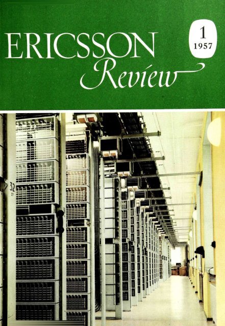
ERICSSON REVIEWVol. XXXIV No. 1 1957RESPONSIBLE PUBLISHER: HUGO LINDBERGEDITOR: SIGVARD EKLUND, DHSEDITOR'S OFFICE: STOCKHOLM 32SUBSCRIPTIONS: ONE YEAR $ <strong>1.</strong>50; ONE COPY $ 0.50CONTENTSMaintenance of Aarhus AreaExchangesMechanization of the AlandTelephone NetworkConnecting and Protector Stripsfor Main Distribution FramesVisual Staff Locator System forSmall and Medium-sized OfficesTraffic Signals at Vasterbron,StockholmL M Ericsson Exchanges Cutinto Service 1956L M Ericsson News fromQuarters of the WorldAllpage291419232831On cover: The switchroom at Centrumlocal exchange, Aarhus: L M Ericssoncrossbar systemCOPYRIGHT TELEFONAKTIEBOLAGET LM ERICSSON • PRINTED IN SWEDEN, ESSELTE AB, STOCKHOLM 1957
Maintenance of Aarhus Area ExchangesM AHM, CHIEF ENGINEER, JUTLAND TELEPHONE COMPANY (J.T.A.S.), AARHUS, DENMARKU.D.C. 62<strong>1.</strong>395.722.004.5Six automatic local exchanges and a trunk exchange of L M Ericsson'scrossbar system were opened in the Aarhus area on May 1, 1953. An articlein Ericsson Review No. 311953 gave an account of the design of the system.The present article deals with the methods of maintenance and the results ofoperation for the first six months of 1956.All six local exchanges use the ARF 10 system. The largest is the mainexchange. Centrum, with 20,000 lines. The remaining five, with a total of12,000 lines, are suburban exchanges. The trunk exchange uses the ARM 20system with a capacity of <strong>1.</strong>600 trunk and toll lines. It is operated jointly bythe Danish P.T.T. and J.T.A.S.The Centrum and trunk exchanges are installed in the same building. Theequipment rooms are painted with turpentine-free paint, and the floors arecovered with linoleum. The Centrum and trunk switchrooms have air conditioningsystems with humidifiers, while the suburban exchanges have not.Where humidifiers are employed, the relative humidity remains steady at about60 % ; in the suburban exchanges it fluctuates between 30 % and 70 %.During the run-in period, maintenance consisted mainly of periodic routinetests <strong>com</strong>bined with trouble clearing. In course of time routine tests were madeat less frequent intervals, and now, at Centrum, they are performed only asrequired. In the near future the same procedure will be adopted at the suburbanexchanges. A system of qualitative service control, consisting of the<strong>com</strong>pilation of statistics based on regular traffic tests, congestion metering,alarm panels, and the like, will be introduced. Only if the statistics reveal irreg-V~ r~[if TXFig. IX8013The J.T.A.S. head office in AarhusThe left-hand side of the building houses theCentrum and trunk exchanges.2
ularities serious enough to affect service, will routine tests be instituted totrace the trouble. Faults observed by subscribers or operators will in mostcases be reported to the wire chief's desk. Various forms of automatic routiners,such as traffic route testers, exchange testers, tariff testers, line testers.and register testers, are available.The maintenance program can be classified as follows:Syd5000 nos.Fig. 2Local exchanges in Aarhus area<strong>1.</strong> Localization of faults (traffic tester, centralograph, inspection, routinetests).2. Clearing of faults.3. Cleaning of exchange equipment.The first two categories of maintenance work are performed by exchangemaintenance men assisted by trainees. Cleaning of exchange equipment isdone by women.Maintenance of Local ExchangesThe quantity of maintenance work is dependent on the size of the exchange,the number of lines in service, traffic density, and the like. Some data ofinterest pertaining to the local exchanges in the Aarhus area are given intable <strong>1.</strong>Table iNo. subs,at 1/1/56SL (outg. + inc.)erlangs/100 subs.Busy hour trafficI GVeilangsII GVerlangsOutg. callsper sub.and dayCentrum ....VestBrabrand ....Risskov ....Skaade ....Syd14,8022,3935601,667<strong>1.</strong>0743,5867.04.94.64.85.14.949510120.764.843.21435189.06.56.05.86.25.924,0826.28685187.9The number of calls per subscriber and day is calculated as the Monday—Friday average. On a day with heavy traffic the originated calls per subscriberon the Centrum exchange may number about 11, and in<strong>com</strong>ing calls roughlythe same.The holding time on originating calls averages 105 sec.» » » » in<strong>com</strong>ing » » 1 15 »Register holding time is 10 »The busy hour calling rate is 1<strong>1.</strong>5 for originating calls and 12.5 for in<strong>com</strong>ingcalls.In accordance with the customer's specifications the equipment was designedfor a congestion of 0.2 % in every switching stage, with total congestion notexceeding 1 %. At 10% overload the congestion must not exceed 1 % perswitching stage. The filling grade for the individual thousands groups, however,is not especially high, and only on rare occasions does the volume oftraffic approach that for which the equipment was designed, so that congestionseldom arises.As already stated, now that troubles associated with the installation andrunning-in period have largely disappeared. J.T.A.S. has confined routinetesting to the Centrum exchange and only uses it there as required. The
'Fig. 3 x 8014The Aarhus Syd exchangemethod employed instead is test calls, which were formerly made by operatorsbut are now performed by Ericsson's traffic route tester. Owing to the rotaryoccupation of the switching devices, an excellent survey of how the exchangesare working, and of their condition, is obtained by calling test numbers in thevarious thousands groups.Table 2 shows the result of some 50,000 test calls made in the first sixmonths of 1956 between 32 local numbers in the 32 thousands groups of theAarhus local exchanges. The calls were distributed among the exchangesaccording to their size.Table 2RouteNumbertest callsFaults andcongestion(quant.)Faults andcongestion(in %)Centrum, internalSuburban, internalCentrum—suburbanSuburban—CentrumSuburban—suburban20,0305,8509,4258,5756,000194141690.090.070.150 190.1549,880620.12The percentage of faults, including congestion, averages about 0.1 %. Thelargest percentage of faults is on inter-suburban exchange traffic. The reasonstor this are that congestion is calculated to be 0.5 % on junction circuitsas against 0.2 % in the switching stages, and also that more equipment iscalled into use. However, the fault percentage is so low that, including congestion,it is below the congestion specified in the tender.Faults found in automatic tests, as well as service <strong>com</strong>plaints, are recordedon trouble cards and detailed trouble reports. As far as possible the faultsare traced and cleared. The number of faults and their nature are set out intables 3 and 4, covering the first six months of 1956. During that perioda total of 421 cards were dealt with at Centrum, and 166 cards at the suburbanexchanges. Of the faults reported at Centrum, 271 were cleared, while150 remained untraced. The corresponding figures for the suburban exchangeswere 127 and 39.4
Faults at Centrum Jan.—June 1956.Table 3Out-of-adjustment faults 71Dirty contacts 19Burnt contacts 4Sticking armatures 2Opens 16Shorts 39Leakage 4Soldering faults 13Installation faults 4Parts out of position 31Burnt-out coils or resistors 18Wear 1Defective <strong>com</strong>ponents 22Other faults 22Total 266Faults at suburban exchanges Jan.—June 1956.Table 4Out-of-adjustment faults 39Dirty contacts 3Burnt contacts 0Sticking armatures 4Opens 10Shorts 20Leakage 1Soldering faults 3Installation faults 1Parts out of position 23Burnt-out coils or resistors 12Wear 1Defective <strong>com</strong>ponents 5Other faults 5Total 127The time spent on maintenance, including supervisor's time, at the Centrumand suburban exchanges during the first six months of 1956 was as follows:Centrum4.229 hoursSuburban exchanges .... 2,447 »The numbers of lines at the Centrum and suburban exchanges are 20,000and 12,000 respectively. On the assumption of similar conditions during thesecond six month period, the time spent on maintenance per subscriber's lineand year would beCentrum0.43 hourSuburban exchanges 0.41 »Routine tests are still retained to a certain extent at the suburban exchanges.When this procedure is discarded, and tests are only made as required, themaintenance time at the suburban exchanges will undoubtedly be considerablyreduced.The working hours at Centrum are from 7 a.m. to 4.15 p.m. on weekdays,7 a.m. to 1 p.m. on Saturdays. The suburban exchanges are unattended.Technicians are called in the event of serious trouble outside workina hours.5
Fig. 4X8011Aarhus is a central point in the Danishtrunk network with direct junctions tomost main exchanges in the countryMaintenance of Aarhus Trunk ExchangeThe Aarhus trunk exchange, as already mentioned, is run jointly by theDanish P.T.T. and J.T.A.S. Maintenance and fault clearing are the responsibilityof J.T.A.S.When the Aarhus trunk exchange opened, a large proportion of manualoperation was considered necessary. Later, automatic operation was used moreand more, the Aarhus subscribers and manual exchange operators themselvesdialling the distant subscriber's number or manual exchange, as the casemight be. This necessitated extensive changes in the trunk exchange, whichhave naturally affected the maintenance situation.The trunk circuits to and from Aarhus consist of two-wire and four-wirelines. For the two-wire toll lines there are two switching stages with 400outlets each and a load of roughly 100 erlangs per stage. The trunk circuitsalso have two switching stages with 400 outlets each, the load being about240 erlangs per stage. The numbers of circuits terminating at the trunkexchange as at July 1, 1956. are tabulated below.Table 5Type of circuitInc.Orig.BothwayTotalInternational circuitsP.T.T. circuitsJ.T.A.S. trunk circuitsToll circuits . .8 31918889189592827629292006563853622836051,250The holding time of connections on trunk circuits is about 250 seconds andon toll circuits about 205 seconds. The busy hour calling rate is 12.3 % forboth types of circuit.
The same practice is adopted at the trunk exchange as at the local exchange,that traffic tests are performed in order to check the quality of service andfor fault tracing purposes. But routine tests—of tariffs, registers, lines, andthe like—are also retained to a much greater extent at the trunk exchange.The tests are at present done at fairly frequent intervals, but it has not yetbeen decided whether this will continue in future. The centralograph, whichis connected into the circuit every time a fault condition arises, is a greathelp in tracing. The intention had been to record the faults indicated by thecentralograph on punch cards, and so obtain an overall picture of the faultsand their frequency in different parts of the equipment. However, the faultshave proved too few to justify the use of this method.In traffic tests during the first six months of 1956 there were 23,080 callsto trunk exchanges. The faults numbered 480 or 2.08 %. They are classifiedin table 6, from which it is seen that the fault percentage at the trunk exchangeand local exchange is only 0.60 %.Table 6Total number of test calls 23,080Number of faults on line, repeater station ordistant exchange 342 <strong>1.</strong>48 %Number of faults at local or trunk exchange .... 138 0.60 %480 2.08 %Altogether 279 fault cards were handled during the first six months of 1956,of which 263 were cleared and 16 remained untraced. The faults are specifiedin table 7.Table 7Out-of-adjustment faults 121Dirty contacts 9Burnt contacts 2Sticking armatures 1Opens 13Shorts 34Leakage 1Soldering faults 36Installation faults 5Parts out of position 7Burnt-out coils or resistors 12Wear 9Defective <strong>com</strong>ponents 13Other faults 0Total 263In addition, 147 faults occurred in the switchboard operators' equipmentand a few out-of-adjustment faults on keys.The time, including supervisor's time, spent on clearing faults at the trunkexchange during the period was 6,026 hours. Assuming the same conditionsduring the second six months, the time spent on maintenance per line andyear would be 9.7 hours.The number of connections established through the trunk exchange isabout 24.6 millions a year. Thus the maintenance time per 10,000 connectionsis 4.9 hours.7
Table 8 shows the lost calls due to busy route, conflicting call on bothwayline, internal congestion and faults in the trunk exchange markers. The tableis based on the average of the period 9.30—10.30 a.m. for the first six monthsof 1956.Table 8Ma rkersoriginati ng trafficNumber0Markersin<strong>com</strong>ing trafficNumber%OccupationsEstablished connectionsBusy routesOther lost calls4,7854,2734684410089.29.90.95.8735,356452651009<strong>1.</strong>27.7<strong>1.</strong>1Specification of other lost callsConflicting callsInternal congestionFaults224180.40.10.41827200.30.50.3As shown by the table, the number of non-established connections in thebusy hour was roughly 10%, the main cause being 8—10% busy routes.As already mentioned, the service data given in this article are averagedata only. But it can be said that at the present time the exchanges are workingto the full satisfaction of subscribers, and there is no doubt that with carefulmaintenance the trouble rate should be low and the expenditure on maintenance<strong>com</strong>paratively slight. Maintenance time must of course not be cutbelow the point at which constant satisfactory service can be provided. Onthe other hand, entirely trouble-free service should not be considered necessary,since the last per mille of faults would be very expensive to eliminate.8
Mechanization of the Aland Telephone NetworkKNUT VON SCHANTZ, LANDS TELEFONANDELSLAG, GODBYU.D.C. 62<strong>1.</strong>395.34(480.3)In many countries where telephone networks have been converted toautomatic operation the need for <strong>com</strong>paratively small rural exchanges soonbecame apparent. L M Ericsson's first rural exchange of crossbar type wasdelivered to the Swedish Tele<strong>com</strong>munications Administration in 1946. Sincethen 68,550 lines have been placed in service up to Jan. <strong>1.</strong> 1957.In the present article Mr. Knut von Schantz, head of the A lands Telefonandelslag,gives an account of the results attained through the mechanizationof the Aland network. The article was earlier published in the Finnish journal"Puhelin". but has been revised to include the latest available data.There is a general belief on the mainland that Aland consists of countlessislets and skerries, the inhabitants of which live on fishing and seafaring.Closer acquaintance with the islands, however, brings a different view. Themain island is, in fact, 1,500 sq. kilometres in area with extensive forests,hills and fertile valleys and plains. Several hundred kilometres of roads windthrough the countless villages of the nine parishes, and the thousand oddcars of the 20,000 inhabitants have all the space they need to move about in.— And nonetheless this natural beauty-spot possesses 6,654 rocky islets andskerries of every shape and size spread among a further six parishes.This the most westerly of Finland's telephone zones counts some 4,200subscribers on 50 or so exchanges. The main islands of Aland and Vardohave about 3,500 subscribers. The remaining 700 are scattered throughoutthe surrounding archipelago. Among the former, 1,500 are served by MariehamnsTelefon AB, and the remaining 2,000 by Alands Telefonandelslag.Among the archipelago subscribers 400 in the outer fringe <strong>com</strong>e under theFinnish P.T.T., and 300 on Foglo are distributed among five small undertakingswith as many exchanges.Dial telephones are at present possessed by Mariehamn's 1,500 subscribers.The population of Mariehamn and environs is 6,000. A further 1,000, orone half, of the Alands Telefonandelslag subscribers are connected to theautomatic network. Of the entire number of subscribers 60 % have dialtelephones.Thus it will be seen that the telephone density of Aland is 21 subscribersper 100 inhabitants—in Mariehamn alone 25—<strong>com</strong>pared with 11 per 100 forthe whole of Finland.Opening Stages£P£In 1944 the cable plant of Alands Telefonandelslag had deteriorated to suchan extent that the transfer of the entire undertaking to the P.T.T. appearedthe only possible course. At the last minute, however, it was decided to keepthe <strong>com</strong>pany intact; and since the P.T.T. granted a respite of two years toput the network in order, an intense work of reconstruction was set in motion.Fig. IMap of AlandMariehamn had gone over to automatic working in 1942 with the installationof L M Ericsson's AGF system based on 500-line selectors. But it wasto take ten years before the example was followed in the rural areas. The1*— 70.5917
.6f/cARK 3/s/'60*8S00-*S999TcboUARK3l2/*0*8*00-*8*99Eckero35300-3S5399_ARK3IS/,Morby5(romsv,k^ ARK3'*/'00 ^6300^\3560O-35799GoabuARK33Sjl50*6OC0-*629$MetlontjrpARK 3 I2j*035300-35339^ICullo ARK 3t*/i035800-35639Vesiorsundo-£5Kj3tf/'S0•-Jwr~~~QJARK 335/260*8000-*8399SanqsbuPARK3/5//60799 5ibbyARK 3W/60*7300-*7*99To5crbuARK 3t*/60*6dOO-*69S9JomaloAM335/200,33000- 33339OnninyebaARK 3121*033700- 33833em5undlandARK 3/*/d0* 7000-* 7799ARK 335//605*000- ' ^39L umporlondARK 3/t/fOO3*500-3*639Vcdo—• ARK 31 it I tOO
The quality of cable construction would have suffered, since satisfactoryresults depend largely on careful and accurate planning and efficient management.The network <strong>com</strong>prises some 14,000 poles and 100 kilometres of overheadcable. Part of the plant had admittedly been reconditioned by 1952, butthe larger part of the work remained to be done.The indispensable investment in the network for the years 1953—1960was estimated at 117 million marks, covering the following average annualrequirements of materials: 1,200 impregnated poles, 9,000 kg 2 mm steelwire, and 3.5 million marks worth of cable. Linesmen's wages amount tosome 4 million marks per annum.The trunk cables consist of old 3 mm steel wire, and. on grounds ofattenuation, must in due course be replaced by 2.5 mm copper wire in manyplaces.Between group centres and terminal exchanges 2 mm copper cadmiumwire is already being used, as well as for very distant subscribers.Mariehamn—Jomala is to be loaded in the near future, and Odkarby—Mariehamn is to be provided with a carrier system, so attaining an attenuationgain of 0.2 nepers at the Odkarby group centre. Vardo is to be connectedin due course to Jomala by radio link. Subsidiary automatic exchanges andparty lines have been successfully employed where justified on economicgrounds. Nevertheless the principle has been to employ these systems onlywhen absolutely necessary for economic reasons. Such expedients alwaysimply some kind of makeshift, with the restrictions attendant thereon.The Zone CentreThe equipment needed at the zone centre at Mariehamn for mechanizationof the rural area has been procured by Mariehamns Telefon AB. A writtenagreement has been drawn up in respect to its joint use. An automaticswitchingstage of L M Ericsson's type ARM 50 (GVN) for 24 volt operationwas brought into use in September 1956. At the same time the dial lines11000-11999S.,'[RegI-GVLV<strong>1.</strong>1-6VLV12000-12999Qkj] GIV-Nx8012Fig. 3Mariehamn local exchange (linefindersS, 1st group selectors I-GV and finalselectors LV) and the transit stage oftype ARM 50 (GVN) with junctionsFIR-L and FDUKR to Mariehamn andother exchanges11
(UPLR) of the manual trunk exchange were transferred from the linefinderstage in the AGF exchange to the ARM 50 stage, and the registers werechanged for 5-digit numbering. Simultaneously with the ARM 50 stage, the<strong>com</strong>pany had ordered the installation of a new power plant for 24 volts50 amps. Thus when long distance subscriber dialling is extended to Aland,there will be equipment ready to receive the long distance circuits on a 4-wirebasis. Mariehamn also administers Jiirso exchange with its 30 subscribers,which is to be converted to the crossbar ARK system in 1957. The muchdiscussed underwater mine at Nyhamn will be among the subscribers of thelatter exchange.BuildingsThe rural automatic exchange buildings have been constructed of wood,the walls being made of old telephone poles that are still in reasonable condition,sawn down to 4" • 4" and bolted together. The walls were thereaftercovered off with insulating material. The cost of such buildings ranged from225,000—500,000 marks according to the size of the building. Owing to thekey position of the Godby exchange, however, the latter building was constructedof Siporex blocks (30 cm, k = 0.5). It measures 4x8 metres andcosts 750,000 marks. On the other hand there is an annual saving of about7,000 marks on fire insurance premiums as <strong>com</strong>pared with a similar woodenbuilding. Power consumption up to now has amounted to about 70 kWhper cu.m. per annum, maintaining a minimum temperature in the automaticexchange buildings of 5—8° C. By pressing the minimum temperatureto + 1 ° C, however, it should be possible to lower the power consumption.The Mariehamn building has been extended on the north side by some10 metres to ac<strong>com</strong>modate the ARM 50 equipment, the M.D.F. being placedbetween the local exchange and the transit stage. The extension also providesspace for the new power plant with its distribution board.FinanceTo finance the extensive project, the Alands Telefonandelslag decided toraise the deposit from 10 to 30,000 marks per share, to be paid up over anumber of years. The installation charge was fixed at 20,000 marks withina 3-kilometre area, and the annual subscription at 7.000 marks irrespectiveof distance.In 1952 operators' salaries amounted to 8 million marks per annum. Theyhave now fallen to half that amount, and the saving well covers the interestand amortization on the investment in automatic equipment and buildings.The long term debt is at present 42 million marks and is calculated to riseto 70 million by 1960. By that time the outside plant will have been practicallyentirely renewed. Plant, property and equipment is expected to stand at about150 million marks at the same date. The <strong>com</strong>pany's annual budget at presentruns at about 55 million marks. After 1960, when all larger outlays havebeen <strong>com</strong>pleted, it should be possible to reduce outstanding debts fairly rapidlywhile at the same time lowering the tariffs.System of Charges and Numbering SchemeThe <strong>com</strong>pany's previous charges, in manual and automatic areas alike,were 4 marks for local calls and 12 marks for a 3-minute zone call includingthe basic impulse in the automatic area. The automatic charges have nowbeen unified to a single tariff of 10 marks per 2 minute period irrespectiveof the origin of the call. The reason for this step was the difficulty of arrivingat fair rates for the different parishes since the group area boundaries andparish boundaries do not coincide. Moreover, one parish may have one
exchange, while another has perhaps two or three. Thus the basic impulse feehas been deducted from the previous automatic charge, and local calls arecharged on a time basis.The local fee in Mariehamn is now 2 marks a minute, and for calls to ruraldistricts 5 marks a minute—the same charge as within the rural network.The tariffs of the manual group are 15 marks per 3 minute call to ruraldistricts and 5 marks per local call.When the ARM 50 stage was taken into use, 5-digit numbering was adoptedthroughout the entire automatic area including Mariehamn. By this meansMariehamn. which is growing steadily at a rate of nearly 100 subscribers ayear, was assured of an adequate number reserve. At the same time thefuture connection of the outlying islands to the automatic area will be ableto take place without friction.Staff PolicyAn important role in any reconstruction project of this magnitude, involvinglarge investments and difficulty in obtaining capital, is played by thestaff, whose <strong>com</strong>petence and proficiency will have a decisive effect on thefinal success. Special attention must be paid to the powers of leadership,sense of responsibility and proficiency of foremen and others in keypositions. If the care of pole lines, cables and exchange equipment—not tomention stores, office work and motor vehicles—can be entrusted to capablehands, the managing director and chief engineer will be freed from manyunnecessary worries and the <strong>com</strong>pany will save substantial sums every year.Thought must likewise be devoted to the training of craftsmen and to thequestion of how to get trained staff to remain in the <strong>com</strong>pany's service. Itmay be pointed out here that Alands Telefonandelslag pays 50 % of the costof correspondence courses taken by its employees whenever such studies areconsidered of benefit to the <strong>com</strong>pany. In addition, the <strong>com</strong>pany pays for thetraining of capable fitters at Helsinki and Stockholm.With a view to binding the staff to the <strong>com</strong>pany, all salaried employees 24years of age and with 3 years in the <strong>com</strong>pany's service are granted a pensioninsurance. The insurance includes full retiring age pension in addition toinvalidity and family pension and funeral expenses. The <strong>com</strong>pany pays 2 /3,and the employee Vs. of the premium. The employee's share amounts on anaverage to 6 % of his salary. Other social benefits, such as staff housing etc.,are provided as far as the <strong>com</strong>pany's finances permit.Public RelationsAn important factor—perhaps the most important for successful operation—is good relations with subscribers. A speedy trouble clearing service, politenesson the part of repairmen, the production of visible results, and anefficient information service in regard to all changes affecting subscribers,are examples of the means to strengthen these relations.—At a later stage asystem of systematic observation of traffic conditions should be started, basedon statistics, and the results should be used to maintain the quality of serviceabove a minimum level of profitability and satisfaction to subscribers.By the time Alands Telefonandelslag has <strong>com</strong>pleted the mechanization ofits area in 1960, it will have roughly 4,000 dial subscribers. Of the remainingmagneto subscribers, it should be possible to link up the 300 Foglo lineswith the rest of the network. Under present conditions, on the other hand,it is hardly conceivable that the 400 P.T.T. subscribers in the outerarchipelago can be put on dial service without great financial sacrifice. Buttechnical progress is rapid, and within a few years the conditions will bechanged by the electrification of the archipelago—a fundamental condition forthe fullscale conversion of this part of the area to automatic working.13
Connecting and Protector Strips for MainDistribution FramesE NYLUND, TELEFONAKTIEBOLAGET LM ERICSSON, STOCKHOLMU.D.C. 62<strong>1.</strong>395,669The connecting and protector strips made by L M Ericsson have undergonevirtually no change for many years. They are rather bulky, however, and thismay prove a serious inconvenience especially in rapidly growing telephonesystems. A new connecting and protector strip with pairs on 10 mm centreswas therefore designed, occupying only two-thirds of the vertical spacerequired by the previous strip. The strip is <strong>com</strong>posed of standard elements,so is simpler to manufacture, pack and install. New and more efficientexcess current cut-outs and over-voltage arresters have been designed at thesame time.Protector Unit CombinationsThe most <strong>com</strong>mon method of protection used in telephone exchangeshitherto consisted of a <strong>com</strong>bination of three protector elements placed in thefollowing sequence: nearest the line a fuse which usually blows at 3 amps.;thereafter an over-voltage arrester, normally consisting of carbon blocks withmica separator, for protection against atmospheric discharges; and, on theexchange side, a heat coil which operates to long-duration "sneak" currents ofmin. 0.15 amp. This form of protection was originally designed since theexternal plant consisted largely of open wire lines.Many areas are nowadays served entirely by metal sheathed cables and donot require so high a measure of protection; the over-voltage arrester at anyrate must be considered unnecessary in such areas. If there is any risk ofsneak currents or contact with power lines, however, excess current cut-outsshould be installed. Sneak currents, if of sufficient duration, may unduly heatthe coils of line relays. The current at which the heat coil operates must beabove the transmitter current at the lowest line resistance, but below thesneak current that would cause overheating of the line relays.L M Ericsson has designed a new fuse which is a <strong>com</strong>bination of ordinaryfuse and heat coil. In this <strong>com</strong>bined fuse the current passes through a smallheater element soldered to a straight fuse wire. At sneak currents exceeding0.15 amp.—the minimum fusing current—the solder melts and disconnectiontakes place with roughly the same time lag as in the old heat coil. At currentsabove 2—3 amps, the straight wire fuses first, and very quickly, as shown infig. 7. The <strong>com</strong>bined fuse is described in greater detail below.x2147Fig. iMain distribution frame type BAB 12showing old connecting and protector strips(left) and the new designs (right)On the fringes of an exchange area long stretches of line may consist ofbare wire or self-supporting insulated wire. Over-voltage protection will berequired at the distribution points between bare wire and cable. Hazardousvoltages caused by atmospheric discharges or by contact between the barewire and a power line cannot enter the telephone cable or the exchange ifthe over-voltage protector operates in the required manner. It may happen,however, that part of the voltage wave from the overhead line continues tothe exchange owing to high resistance to earth or to a fault in the protectorelements. But this wave cannot attain higher amplitude than the breakdownvoltage of the cable, which is usually limited to 2,000 volts. Under such14
Fig. 2 X 6975IO-pair strips(From left) connecting strip NEL 1100, protectorstrip NFL 3111, and protector stripNFL 3211conditions it may be advisable to place over-voltage arresters in the protectorstrip at the exchange. A new over-voltage arrester has been designed. Itconsists of two metal electrodes pressed into a plastic tube to providethe proper spark gap. The 3-amp. fuses employed up to now, the main objectof which was to prevent overheating of the over-voltage arrester, have been discarded.The new over-voltage arrester cannot be overheated since, whenheated up, the plastic tube softens and the electrodes are forced together bythe mounting springs, so providing a direct circuit to earth. The overvoltagearrester is described in greater detail below.Opinions in regard to the proper protection for exchange equipment will,110 doubt, always be divided. However, the present trend is towards a reductionin the number of protector elements at exchanges served by cables. Thereare already exchanges at which all protection has been discarded, or atwhich an ordinary 0.5 amp. fuse alone is retained. The new strip has thereforebeen designed for use either with or without different <strong>com</strong>binations ofprotectors.Connecting and Protector StripsThe new connecting and protector strips are made up in 10-pair units. The10-pair strips are assembled on a <strong>com</strong>mon mounting (fig. 3), which willcarry 10, 20 or 50 pairs. Several 50-pair mountings can be placed one abovethe other in the M.D.F., as previously.5>The 10-pair strips are made in various forms to cater for different <strong>com</strong>binationsof protector elements. Consequently different categories of lines,even in one exchange, can be protected in different ways. These differenttypes of 10-pair strips are interchangeable without reforming of the cables.Similarly, they are capable of replacement by other not yet existing types, asnew ideas and designs of protector are produced. In the new strip the sectionsfor alarm and interception circuits have been omitted. The alarm device wasconsidered unnecessary since it functioned only on operation of the heat coil.Trouble of this kind represents only a very small fraction of the total interruptionsto telephone service. The interception circuits are now terminated onthe test jack strip. A main distribution frame is shown in fig. 1 with two50-pair strips of the old type alongside three 50-pair strips of the new type.Fig- 350-pair protector mountingAt present five different 10-pair strips are being manufactured, as listed intable <strong>1.</strong> They have soldering tags on the line side and screw terminals for thejumper wires.15
Fig- 4Label holder NBM miTable IStripProtector elementsConnectionNEL 111)0-0HZ)NFL 3101NFL 3111Fuse NGH 2201 (0.5 A)Combined fuse NGH 5001-05-2)NFL 3201NFL 3211Fuse NGH 2202 (1 A) and overvoltagearrester NGA 3001Combined fuse NGH 5001 andover-voltage arrester NGA 3001L ^ 1||..o~X—|-0sFig. 2 shows three of the 10-pair strips tabulated above, viz. NEL 1100,NFL 3111 and NFL 321<strong>1.</strong> They are assembled on a frame of nickel-platedbrass sheet, which at the same time constitutes the earth connection for theover-voltage arresters. The 10-pair fuse strips NFL 3101 and <strong>com</strong>bined fusestrips NFL 3111 are of identical construction, differing only in the protectort^x6977Fig. 5Over-voltage arrester NGA 3001 (left)and <strong>com</strong>bined fuse NGH 500116
•G rLrlFig. 6The <strong>com</strong>bined fuse NGH 5001A end capB fuse wireC glass tubeD rodE solderF helical springelements. Similarly the 10-pair strips NFL 3201 are of identical constructionto strips NFL 321<strong>1.</strong> The pairs are on 10 mm centres. Every installed 10-pairstrip occupies a vertical space of 105 mm.The contact springs, of tinned german silver, are assembled on plasticblocks with high insulation resistance to breakdown and leakage currents.The leakage current paths are at least 4 mm long, which suffices forindoor installation. Under the connecting screw is a slot for the wire. Thisarrangement greatly simplifies the wireman's work, as the end of the wireneed not be formed into a loop.The Protector MountingFig. 3 shows a protector mounting for five 10-pair strips. When carryingover-voltage arresters, the mounting at the same time serves as earth connection.As stated above, mountings are made for one. two and five 10-pairstrips. No waste of space is involved in placing several mountings one abovethe other. For instance, one 10-pair and two 20-pair mountings occupy thesame space as a 50-pair mounting. The mounting is made of nickel-platedbrass and has earth terminals at each end. It also carries fanning strips forthe jumper wires. The fanning strips are made of anodized aluminium. Theanodization provides satisfactory protection against corrosion and is electricallyinsulating.1000100101,iVsAB\nni0,1 0,2 0,5 1 101|11111\\\ •*Fig. 7 X 2150Fusing curve of <strong>com</strong>bined fuse NGH5001Label Holder NBM 1111Every 10-pair strip can be fitted with a label holder as shown in fig. 4. Twospring catches permit the holder to be pushed into position without needingto be secured by screws. It is supplied with label and transparent protectingplate.Over-voltage Arrester NGA 3001This protector, illustrated in fig. 5, consists of two cylindrical metalelectrodes of a patented alloy which are pressed into a plastic tube so as toproduce the proper gap between them. The breakdown voltage is 700—<strong>1.</strong>000 volts d.c. As in all over-voltage arresters of this type, the strikingpotential increases by 10 to 20 per cent on steep wave front voltage surges.Its load capacity is greater than that of carbon arresters. Arrester NGA 3001withstands a large number of discharges of up to 0.2 coulombs, whereascarbon arresters are often short-circuited at 0.1 coulombs. In the event of apermanent arc being formed, the electrodes be<strong>com</strong>e heated. This causes theplastic tube to soften, whereupon the electrodes are forced together by themounting springs so that the line be<strong>com</strong>es earthed. The protector must then bereplaced.Combined Fuse NGH 5001This fuse, illustrated in fig. 6, is of a patented design. The end caps A andthe glass tube C are the same as in fuse NGH 22. F is a helical spring which,at point E, is attached by a solder of low melting point to the metal rod D.Also soldered to point E is an insulated resistance wire, which is first wounda number of turns around the rod and then continues in the form of fusewire B. At fairly low currents the rod heats up until the solder at point Emelts. Owing to the relatively large mass of the rod. a certain period elapsesbefore the break occurs. At high currents wire B melts very quickly, andbefore the solder. Fig. 7 shows the fusing curves of the solder (A) and theA fuse wire (fi). The curve of the <strong>com</strong>bined fuse unit thus follows the fullvdrawn line. The resistance of this fuse is only about 4 ohms. The resistanceof the old type of heat coil was 8 ohms.17
Fuse NGH 22In conjunction with the redesign of the connecting and protector strips thefuses have also been modified to some extent, the end caps now being madeof thin brass sheet instead of being turned out of bar stock as earlier. Theyhave also been flanged to prevent the fuse from slipping in its holder. The newfuses are designated NGH 22 and replace the former type NGH 20.InstallationThe new connecting and protector strips can be fitted to main frames BAB12—14 and other types. The frame need only be equipped with a simplefixing bar holed to take the new strips. Fitting of the fixing bar can be donewithout difficulty while the main frame is in service. If old type protectorstrips are replaced by new types, the cables must be reformed. If the stripsare supplied <strong>com</strong>plete with mounting they are numbered as in the table below.Protector mountings, 10-pair strips and protector elements are packedseparately for shipment. The mountings should be erected in the frame first.The switchboard cable should then be formed as shown in fig. 8. The 10-pairstrips, from which the inside terminal blocks are removed, can thereafter bescrewed into position and the cable connected as in fig. 9. As seen in thephotograph, the fanning strips on the protector mounting are so constructedthat the formed cable need not be threaded but can be laid directly intoposition.Fig. 8X6978Table 2Cable, 50-pair, readyformedCode no.CapacitypairsConsisting10- jair stripsNumber Code no.ofProtectormountingNEL 1101NEL 1102NEL 1105102050125NEL 1100» »» »479079479080475155NFL 3131NFL 3132NFL 3135102050125NFL 3101» »» »479079479080475155NFL 3141NFL 3142NFL 3145102050125NFL 3111» »» »479079479080475155NFL 3231NFL 3232NFL 3235102050125NFL 3201» »» »479079479080475155NFL 3241NFL 3242NFL 3245102050125NFL 3211» »» »479079479080475155Fig. 9 X 2151Protector strip with cable ready soldered18
Visual Staff Locator System for Small andMedium-sized OfficesO IRGENS, TELEFONAKTIEBOLAGET LM ERICSSON, STOCKHOLMU.D.C. 654.938L M Ericsson's keyset operated staff locator system with facilities for paging100, or alternatively, 200 persons was described in Ericsson Review No. I,1954. So large a number of signals is seldom needed in small and mediumsizedoffices, and L M Ericsson has therefore introduced the similar, butsmaller system presented in this article.An important part of customer service is a well managed telephoneswitchboard. Customers tend to judge the whole efficiency of an organizationby the speed and confidence inspired by the switchboard operator. Whatthe customer notices is how long he has to wait for connection to the personhe wants to speak to. To be kept waiting merely irritates him—and on longdistance calls costs him money as well. Any firm that wants to show goodcustomer service must make sure that telephone delay is cut to a minimum.A <strong>com</strong>mon reason for telephone hold-ups is that some people, naturally,are kept on the move from one department to another. When the operatorfails to get a person on his normal extension, she tries to trace him in otherparts of the building and put the call through to him there. The quicker sheis able to contact him, the less time will the caller have to wait. An invaluableaid in this respect is a staff locator system.General PrinciplesA staff locator system should meet the following requirements:The operator must be able to send signals from the switchboard tovarious points in the building.Individual and easily recognizable signals must be allocatable to allpersons whom the operator regularly needs to contact.The signals must not be disturbing to persons at their normal placeof work.The manipulations required of the switchboard operator must besimple, and the signal must continue to be displayed until the soughtparty answers by telephone or by other means, or until the operatorcancels it.L M Ericsson's keyset operated, sequence paging system, described inEricsson Review No. <strong>1.</strong> 1954, meets these requirements to the full. Systemsof this kind are mainly adapted to large organizations, and L M Ericsson hastherefore introduced a similar smaller system <strong>com</strong>prising 31 signals withalternative steady or flashing light, so allowing in fact for 62 separate signals.19
Fig. I X 2199Block schematic of systems with keysetKEM 32941 keyset KEM 32942 lamp relay set KFB 153013 lamp indicators4 transformerEquipment and OperationThe new staff locator system is <strong>com</strong>posed of lamp indicators, keyset, lamprelay set and mains transformer, as in the block schematic of fig. <strong>1.</strong>LampindicatorsThe system is based on the principle of visual signalling on lamp indicators.Two kinds of indicator may be used (figs. 2 and 3), the vertical type havingdifferently coloured lenses and the circular type red lenses. In the latter typethe lamps are <strong>1.</strong>2 W and are fully visible at distances of 30 feet and above;in the former type the lamps are 3 W, being visible at 100 ft. and within asector of 180°. Both types of indicator are made for wall mounting and shouldbe placed about 6 ft. from the floor. Thirty-one visual signals are obtainable:five by the lighting of the five lamps individually, twenty-five by different<strong>com</strong>binations of two. three or four lamps, and finally one signal consisting ofall five lamps lighting at once. Since the two kinds of lamp indicator produceentirely different signal patterns, all indicators in one office should be of thesame type. Both types can incorporate a built-in buzzer.Fig. 2 X 4939Lamp indicator KNH 8311with differently coloured lamps in verticalarray. Dimensions: width 90 mm, height 232mm, depth 6l mmThe usual arrangement is to have one lamp indicator in each room andothers distributed as necessary in corridors, stock room, archives, mess roomsetc. The general rule should be that the signals should not disturb personssitting at their desks. These persons can be reached by the operator on thephone, and the whole object of the staff locator system is to contact peoplewho do not answer on their own extensions. The indicators should consequentlybe placed on the wall behind the occupant's desk so that they will cause himno disturbance but will be noticed by other people visiting him.The addition of a buzzer in the indicator may be advisable in corridorsand in localities where visual signals alone are insufficient. Irrespective of theFig. 3X 4943X4940Lamp indicators KNH 9501 for flushmounting(left) and KNH 9511 for surfacemounting(right)Dimensions:KNH 9501: diameter 85 mm, depth 53 mmKNH 9511: diameter 92 mm, depth 41 mm20
Fig. 4 x 8008Keyset KEM 3294placed beside switchboardplacing of indicators, it is a general fact that a steady light is far less apt tocatch the attention than a flashing light, so that steady light signals shouldpreferably be <strong>com</strong>bined with acoustic signals. The buzzer should sound onlywhen the lamp lights, and not continue while the light is on.Keyset and lamp relay setA keyset (fig. 4) for initiating the desired signal on the lamp indicators isplaced at the switchboard. Every signal is represented by a 1, 2 or 3-digitnumber, the keyset having nine keys for this purpose. The keying of a numbersets up the corresponding lamp <strong>com</strong>bination in a separate lamp relay set(fig. 5), and when the operator thereupon presses key A or B, the signal isdisplayed on all lamp indicators. Key A produces a steady, and key Bflashing, light. If buzzers are installed, both keys, by being pressed fully down,operate the buzzers as well. The signal is cancelled and the keys restored bypressing key O between keys A and B.Power requirementsA mains transformer supplies 48 or 24 volts a.c. for operation of thelamp indicators and at the same time, via a rectifier in the lamp relay set.feeds the d.c. circuits in the keyset and lamp relay set. A 48 volt supply isnormal in systems incorporating vertical type indicators, but the lattercan be fitted with lamps for 24 volts if required. The circular indicator isintended solely for the lower voltage. So. too, are the buzzers, irrespective ofthe type of indicator in which they are mounted.CablingFive separate conductors and a <strong>com</strong>mon return circuit are required betweenthe lamp relay set and lamp indicators. If buzzers are desired, one additionalconductor must be installed. A suitable cable is ordinary 12-wire P. V. C.
Fig- 5Lamp relay set KFB 15301(right) with cover removedinsulated telephone cable (EKKX), in which 6 wires constitute the return circuit.All lamp indicators should be connected in parallel, and the cable can suitablybe drawn from indicator to indicator without having to pass through terminalboxes. The voltage drop in the circuit should not exceed 10 % at maximumload. On long circuits it might therefore be necessary to <strong>com</strong>bine the EKKXcable with a heavier feed cable (EKKP).Absence IndicatorPaging signals will, of course, be of no use if the called party is away fromthe office. To avoid paging to no purpose, the system can be supplementedby absence indicator equipment. When the operator keys the number of aperson who has marked himself absent, the signal is blocked by a specialrelay set {KFB 15313) in circuit with the keyset. A signal is at the same timereturned to a time indicator panel, mounted at the switchboard, which informsthe operator of the time at which the person is expected back or that he willbe away all day. These indications are marked by the person himself on anabsence indicator panel at the main office entrance. Every person to beac<strong>com</strong>modated on the system has his own knob on the absence indicatorpanel, which he turns to the required setting whenever he enters or leaves theoffice. The knobs are electrically connected to the relay set and to the timeindicator panel at the switchboard. The absence indicator panel ac<strong>com</strong>modatesequipment for 3 1 persons.The general layout of the system is shown schematically in fig. 6.3 -IFig. 6x2200Block schematic of systems with keysetKEM 3294 and absence indicator1 keyset KEM 32942 lamp relay set KFB 153013 lamp indicators4 transformer5 absence indicator relay set KFB 153136 absence indicator panel at main entrance7 time indicator panel at switchboard6 lOOO o"o"|yy
Traffic Signals at Vasterbron, StockholmBENGT VON MATER N, THE STOCKHOLM TOWN BUILDING OFFICEU.D.C. 656.056(487.1)L M Ericsson's vehicle controlled traffic signals have been earlier describedin Ericsson Review Nos. 3/1950, 1/1951 and 2:1955. The present articlecontains an account of the traffic control installation, with many interestingfeatures, at the Langholmsplan intersection on the approach to Vasterbron inStockholm. In particular a new method of varying the maximum green periods,so providing several signal programmes, is described.Traffic signals of L M Ericsson make were installed at Langholmsplan onthe south side of the Vasterbron Bridge in Stockholm in August 1956. Vasterbronis the only north-south bridge west of the city and has to carry increasingquantities of traffic. At present some 45.000 motor vehicles and trams cross thebridge every day, and at rush hours it is used to maximum capacity. Thisheavy volume of traffic obliged the municipal authorities to widen the bridgeto six lanes and to reconstruct Langholmsplan at its southern abutment.Layout of LangholmsplanLangholmsplan was earlier formed as a roundabout, which meant thatright-turning traffic caused considerable stoppage. Since its reconstruction intoa signal-controlled crossing with right-turn prohibition, and simultaneouswidening of the bridge, the traffic flows more smoothly. The present layoutis shown in fig. <strong>1.</strong> It is seen that the tramway has a large stopping place inthe centre of the intersection. Signals are located at three points: at thejunction of Langholmsgatan—Hogalidsgatan. and at two pedestrian crossingswith push button operation on the east and west of the tram stop. An internallylit "No Right Turn" sign is presented to traffic <strong>com</strong>ing from Vasterbron.Vehicles intending to turn right from that direction are instead directedleft immediately after the bridge abutment and take a newly built road underthe bridge leading to the western part of Sodermalm. Traffic from the oppositedirection is likewise forbidden to swing direct right into Hogalidsgatan.But such traffic is rare and is allowed to turn at point a (fig. 1).Three Interconnected InstallationsThe three signal installations are interconnected, the larger constituting themaster installation (/) with the two others (2 and 3) dependent on it.If no demand has been registered from pedestrian push buttons at 2 and 3,signals at / operate as a normal two-phase system whereas traffic passingsignals at 2 and 3 has right-of-way. Two-way traffic movement takes place onLangholmsgatan during phase A, and on Hogalidsgatan—which has tworight-turn lanes leading onto the bridge—during phase D. The interplaybetween / and 2 is evinced if a pedestrian has required passage at 2. Signalsat 2 thereupon follow the changes at / in the sense that the red aspect is pre-
Fig. I X7712Sketch of siteA signal-controlled street crossing (I) and twosignal-controlled pedestrian crossings withpush buttons (2 and 3). The signals are interconnected.sented to Langholmsgatan at 2 immediately before it is presented at /. Afterthe pedestrian phase at 2 and D phase at /, the light for Langholmsgatan returnsto green simultaneously at the two installations. The reason for theinterconnection is primarily to avoid traffic from the bridge having to queuemore than once per vehicle and to avoid vehicles queuing in the middle ofthe pedestrian crossing at 2.If there is no traffic on Hogalidsgatan, and consequently no need ofright-of-way for that street. 2 changes on operation of the button withoutwaiting for any length of time for impulses from /.Installation 2 may be said to be placed in front of the master installationin the direction of traffic movement. Thus the problem of warning 2 of thechange in the master installation "that has not yet occurred, but which is tooccur" has been solved without difficulty. Although the interconnectionbetween / and 3, the latter being placed behind /, should be simpler, anotherfactor <strong>com</strong>plicates the problem in this instance. This is that 3 is passed bytraffic from two directions, by northward traffic on Langholmsgatan (phaseA) and by traffic from Hogalidsgatan (phase D). Since queuing in front of 3,caused by one of these two streams of traffic, interferes with the other, it wasconsidered advisable to preclude such queuing altogether. On the assumptionthat a pedestrian request has been made at 3, the interconnection <strong>com</strong>es intoeffect in changing / from two-phase to three-phase. The third phase C (about7 sees.) consists of "all red", that is to say the red aspect is presented to alldirections of traffic. During this <strong>com</strong>paratively short phase there is time fora vacuum to form at 3, i.e. the accumulation space 3 is empty of vehicles. Thephase sequence in this instance is such that the last vehicle to pass northwardsfrom Langholmsgatan immediately before the signals switch to the thirdphase—red in all directions—has just time to pass 3 before the pedestrianphase at 3 appears. After the all red phase at / has disappeared, the greenaspect is given to Hogalidsgatan, so that the first vehicle arrives in reasonabletime to be met by green on signal 3.24
Three Programme Vehicle ControlThe signals are vehicle controlled by means of magnetic detectors embeddedunder the asphalt. The detectors operate to all kinds of vehicles and aredirectional. The function of vehicle control—which must now be universallyknown—is that the lengths of the green periods automatically vary from onecycle to the next according to the existing volume of traffic passing the signalintersection, and that at maximum volume the green periods displayed to thedifferent streets are limited to a predetermined maximum time. In normalvehicle controlled signal systems the maximum periods can be adjusted bymeans of knobs, each street and phase having a "maximum knob".Experience abroad and in Sweden has shown that the maximum knobarrangement is usually adequate for the requirements both at peak hours andother times. But it has proved deficient at certain places where the morningtraffic differs markedly in direction and volume from the afternoon traffic,or where other special conditions prevail. Many different procedures havebeen tried out to over<strong>com</strong>e this problem. Since the method of variablemaximum green periods tried at Langholmsplan may be assumed to be entirelynew, a brief description may be of interest.Langholmsgatan has three maximum knobs, as also Hogalidsgatan. Thuseach phase has a "low maximum", a "normal maximum" and a "highmaximum"—programmes I, II and III. The change from one programme toa higher or lower takes place automatically under certain given conditions,as follows:An increase from programme I to programme II for phase A (Langholmsgatanphase) takes place on condition that the maximum period of programmeI has been taken out fully by the traffic in street A n^ times in succession. (n lcan be set on a special n 1 knob from f to 10 units.)An increase from programme II to III takes place under similar conditions.Here there is a n., knob which can be given values other than n .A decrease from programme III to programme II takes place on conditionthat the maximum period on programme III has not been taken out n., timesin succession."*> . ** f ffl 1 IFig. 2x8007Control cabinet and signals at the streetcrossingThe signal head in the centre controls thetramway traffic and in the photograph showsa white arrow. The sign on the signal maston the right indicates »No right turn».25
A decrease from programme II to programme I takes place under similarconditions and with the associated n 4 knob.Hogalidsgatan is similarly equipped with three programmes. So far thefollowing settings have been found suitable:Maximum times onprogramme Iprogramme IIprogramme 111Langholmsgatan(phase A)20 sees.30 sees.50 sees.Hogalidsgatan(phase /))12.5 sees.17.5 sees.25 sees.Number of maximum times takenout by the traffic in sequencen, (I-» II)n, (II -* III)Number of maximum times not takenout by the traffic in sequencen 3 (III—> II) 3n, C11 —* I > 3When the programme selectors are switched off. the installation functionsas an ordinary vehicle-controlled system with maximum times that can beset separately and that are entirely distinct from the maximum times forprogrammes I, II and III.Fig. 3Control cabinetx7714On the left of the left-hand photograph is thecontrol and indicating panel on which differentforms of operation can be set and indicationsof vehicle impulses etc. can be read;in the centre are the maximum time selectors.The latter, shown in enlargement (right), areused for setting the different programmes betweenwhich the system automatically changesso as to adapt the signals as required by thecurrent traffic situation.To arrive at proper settings of the eight n knobs, as also of the maximumknobs, naturally requires a careful study of the traffic. The aim is to selectvalues which cause the signals to follow programme I at nighttime, programmeIII during peak hours, and programme II at other times.Experience gained hitherto has shown that the requirements have beensatisfied. At midday, for example, it may be noticed that programme II alternateswith programme I on Hogalidsgatan, while at the same time programmeIII alternates with programme II on Langholmsgatan. At night programme Iusually occurs on Hogalidsgatan, and programme I or on some occasionsprogramme II on Langholmsgatan.26
x 8009 Ordinary vehicle control implies that the signals change before the termina-X 8010Jf b btion of the maximum time if the traffic intensity diminishes to some extent, „ during a phase. Programme control is a further step in the development of& r B r r(right) in phase Dvehicle control, since the maximum green times as well can be adapted to theprevailing traffic load, i.e. the load during a certain number of successivecycles. The <strong>com</strong>bination of ordinary vehicle control and programme controlhas very great advantages, therefore. The systems described have also provedtheir worth in bringing about a great increase in capacity and in moreflexible handling of the traffic.27
LM Ericsson Exchanges Cut into Service 1956Exchanges with 500-Hnc selectorsTownExchangeNumberof linesTownExchangeNumberof linesArgentineMendozaParanaAustraliaMelbourneBoliviaCochabambaBrazilBelo HorizonteRibeirao PretoColombiaBarranquillaBarranquillaBarranquillaBogota DEBogota DEBogota DEBogota DEBogota DEMedellinMedellinMedellinEthiopiaAddis AbebaAddis AbebaFinlandKarjasiltaKuopioPori BjorneborgSeinajokiTurku/AboMendoza IIPABXPrincipalEstadioSurCentroChapineroLas CrucesMuzuRicaurteAmericalBosqueCentroCentroFilwoha(extension)(extension)(extension)(extension)(extension)(extension)(extension)(extension)(extension)(extension)(extension)(extension)(extension)(extension)(extension)(extension)(extension)(extension)(extension)300050025010004000200010000350015001000300010002000200015002000300010006005001000500300500Italy-North ItalyAdriaChioggiaEsteLegnagoMontagnanaPadovaRovigoS. BonifacioS. Dona di PiaveSchioThieneTrevisoValdagnoVeneziaVeneziaVeneziaVeneziaVeronaVicenzaSouth ItalyAlcamoBarlettaBeneventoBrindisiCaltagironeCapriCasertaCassinoCataniaCatanzaroCosenzaCrotoneEnnaFoggiaGiarre RipostoLecceNapoliNapoliNapoliNapoliNocera InferiorePalermoPalermoCentroLidoMestreMuranoCentroNolanaPorticiVomeroLibertaPolacchi(extension)(extension)(extension)(extension)(extension)(extension)(extension)(extension)(extension)(extension)(extension)(extension)(extension)(extension)(extension)(extension)(extension)(extension)(extension)(extension)(extension)(extension)(extension)(extension)(extension)(extension)(extension)(extension)(extension)(extension)(extension)(extension)(extension)(extension)(extension)(extension)(extension)(extension)(extension)200200100900700240040020020020010050020015006001900202500110020020050060010011050040020007007006001008004070020002500200100030015004000
TownExchangeNumberof linesTownExchangeNumberof linesPalermoRagusaRossanoSiracusaVibo ValentiaLebanonBeirutBeirutMexicoMexico DFMexico DFMexico DFMexico DFMexico DFMexico DFMexico DFNetherlandsRotterdamRotterdamRotterdamNorwayNarvikPorsgrunnStavangerTromsoPanamaPanama cityS. LorenzoPABXChapultepccMadridPiedadRomaSabinoSan AngelZocaloCentrum II1 PABXSchiedam1 PABX(extension)(extension)(extension)(extension)(extension)(extension)(extension)(extension)(extension)(extension)(extension)(extension)(extension)500500400100040075007201500100004003000300050015007500200500250050010003000230GothenburgGothenburgHagforsHalmstadHuskvarnaHallabrottetHiirnosandJonkopingKarlstadKristianstadKristinehamnRopingLandskronaLidkopingLinkopingLudvikaLundMtilndalNorrkopingNykopingOxelosundSaltsjo-JiirlaSmedjebackenSolnaStockholmStockholmStockholmStockholmStockholmStockholmStockholmStockholmSurahammarSodertaljeSolvesborgTrollhattanUppsalaVastervikOrebroOstersundOvriga SverigeOrgryteKortedala1 PABX1 PABX1 PABX1 PABX1 PABX1 PABX1 PABX1 PABX1 PABXI PABX1 PABX1 PABX1 PABX7 PABXHandenHiisselbyMalarhojdenRasundaTullingeUlriksdalOrby1 PABX2 PABX2 PABXPABX(extension)(extension)(extension)(extension)(extension)(extension)(extension)(extension)(extension)(extension)(extension)(extension)(extension)(extension)(extension)(extension)(extension)(extension)(extension)(extension)(extension)(extensions)700020005001001000100120200010005001000260120100014050030014010001201201201602001360500400030003000500400045003005005001000320100060002401480Union ofSouth AfricaCape TownSwedenArvikaBollnasBorasEskilstunaFagerstaFalkopingFilipstadFinspangGavleGothenburgGothenburgGothenburgGothenburgPABX1 PABX2 PABX1 PABX1 PABX1 PABX1 PABX1 PABXHisingenKalltorpVasa(extension)(extension)(extension)(extension)(extension)(extension)(extension)1001601000540300060050014040028014030003000500TurkeyAnkaraAnkaraAnkaraAydinDenizliErzurumIskenderunIzmirNazilliTireVenezuelaCarupanoMeridaSan FelipeBahcelievlerKeciorenYenimahalleKarsiyaka(extension)(extension)(extension)(extension)(extension)Total10002001000100010002000100010001000500400150050020283029
Exchanges with crossbar switchesTownExchangeNumberof linesTownExchangeNumberof linesDenmarkHorsensCopenhagenCopenhagenCopenhagenCopenhagenCopenhagenCopenhagenCopenhagenCopenhagenCopenhagenCopenhagenOdenseRudkobingSkagenFinlandHelsinki/HelsingforsHelsinki/HelsingforsHelsinki/HelsingforsHelsinki/HelsingforsHelsinki/HelsingforsHelsinki/Helsingfors(extension)PAXPABXBagsvaerd (extension)GlostrupKastrup (extension)LyngbyValby (extension)Vestskel (extension)Virum (extension)Yrsa (extension)Haaga/HagaHerttoniemi HertoniisKeskust a/Cent rum(extension)Kapyla/Kottby(extension)Pakila/BaggboleSornainen/Sorn'as(extension)4000180120100050002000100002000100010001000100010001600100030001400500030002000NetherlandsHaagRotterdamRotterdamRotterdamNorwayOsloSwedenAlingsasFinspangMotalaStockholmStockholmSunneViisterasYugo-SlaviaBitoljNiksicPula1 PABXCentrum 11 (extension)Noord 11 (extension)West II (extension)1 PABX1 PAX3 PABXPABXPAX(extension)(extension)Total12075005000300070450030065008601501 30010050040070077300Rural exchanges with crosshar switches, system ARK Rural exchanges with 100-line selectors, system XYCountryNumberNumberof lines*CountryNumberNumberof lines*FinlandItalySweden20183197023602600Norway124310Total416930Total124310* The number of lines includes both new exchanges and extensions of existing exchanges.Exchanges with relay selectors. 100-. 30-. 25- and 12-line selectors(delivered from Stockholm)Exchanges with relay selectorsExchanges with 100-line selectors, system AHDExchanges with 30-. 25- and 12-line selectors, system OLTotalNumber173106330609Numberof lines1474947097002064430
NEWS/romAll Quarters of the WorldL M Ericsson Presents AutomaticExchange to Cali, ColombiaIn September last year a seriousexplosion occurred in the town ofCali, Colombia. Seven lorries loadedwith dynamite exploded while parkedon a barracks square. Eight blocksof buildings were levelled with theground, windows were smashed withintwo miles radius, and the explosionleft a crater 100 yards in diameter.The death roll was very heavy,and large numbers of people wereinjured. The destruction in the townwas appalling. All normal life stopped,military and civilian squads weresent in to assist the injured and clearup after the devastation.L M Ericsson, represented in Colombiaby their affiliates Cia EricssonLtda. contacted the Colombianrelief organization Sendas and, byway of financial assistance, offeredautomatic telephone equipment for5,800 lines of other make that happenedto be available. The gift contributedto some extent to the reliefcampaign for Cali which was set inmotion throughout the country.The head of Cia Ericsson Ltda,Mr. Olaf Gustafson, presented thedeed of gift to the President of Colombia,General Gustavo Rojas Pinilla,at the end of last year. In February1957 LM Ericsson was ableto hand over the gift in concrete formto the Mayor of Cali, Col. AndresMunoz, who officially accepted theequipment on Cali's behalf fromMessrs. Gote Fernstedt and OlafGustafson.Mr. Gote Fernstedt signs the deed oftransfer for the gift to the town ofCali. On his right is the Mayor of Cali.(Below) Mr. Olaf Gustafson presentsthe deed of gift to the President ofColombia.The press devoted much space tothis evidence of L M Ericsson's desireto help. The presentation ceremonywas also televised.The town of Cali has a telephonesystem which differs entirely fromL M Ericsson's, so that the gift wasin no way bound up with a businessdeal-a fact which aroused considerablerespect and appreciation fromthe press and local population.First CrossbarSwitching Exchangein AfricaThe first crossbar exchange inAfrica was installed at Gatooma,Southern Rhodesia, in January to theorders of the Rhodesia Post Office.It is a 1,000-line city exchange ofL M Ericsson's type ARF 50 withequipment for auto-manual trunktraffic. The equipment was installedby the Post Office staff with the assistanceof an L M Ericsson engineerwho remained for six weeks after thecut-over to give instruction to thePost Office maintenance staff. Beforehis departure 10,000 test connectionshad been made without a single faultoccurring, and the exchange has sincefunctioned satisfactorily.31
the keyset type control panel. TheCTC office will also have a traingraph.The Doboj-Zenica plant will be<strong>com</strong>pleted in three stages and be fullyinstalled by 1960.C.T.C. for Jugoslavian RailwaysThe Jugoslavian Railways havedecided to install modern interlockingsystems and centralized traffic control(CTC) on the very heavily traffickedDoboj-Zenica section <strong>com</strong>prisingsome 100 kilometres of thesingle track line between Brod andSarajevo. L M Ericssons Signalaktiebolaghas received an order for theequipment and will also supervise thework of installation.The Doboj-Zenica section hastwelve stations, each with three orfour tracks. The traffic is very heavy,and the present capacity of the lineis inadequate. The capacity will beincreased, however, by the introductionof signalling equipment andCTC, which will render the sectioncapable of carrying the heavier trafficthat is anticipated within the nextfew years.All stations will have relay interlockingplants, but only the four largestexchanges will be equipped withlocal control panels that can be operatedwhen the stations are disconnectedfrom the CTC system. TheCTC office will be located at Doboj,and all stations will normally be controlledfrom it.Some ten road crossings will beprotected by lifting gates and signalsfor automatic control by trains.The CTC system will be of L MEricsson's standard type with the illuminatedtrack diagram separate fromEricsson TechnicsEricsson Technics No. 2, 1956, hasrecently appeared. An article by ProfessorC G Aurell of the ChalmersUniversity of Technology, Gothenburg,entitled "The Equivalent TransmissionLine of a Linear Four-TerminalNetwork. Calculations with Cascade-ConnectedFour-Terminal Networks",describes a systematic procedurefor the calculation of impedancesand powers in cascade-connected fourterminalnetworks. The concept"equivalent transmission line" is extendedto apply also to non-symmetricaland non-reciprocal four-terminalnetworks. The article "New Types ofSections for Zig-Zag Filters" by ProfessorT Laurent, of the StockholmInstitute of Technology, presents newtypes of band-pass sections named"zig-zig" and "zag-zag" sectionswhich can be introduced into a zigzagfilter ladder without producingreflection. This provides full freedomin the choice of attenuation peaks ina filter ladder of this kind.Finally, an article by H Hiiggblomand S Tomner of AB Svenska Elektronror,Stockholm, "Developmentsof the Strophotron", describes thetheoretical and experimental workdone on the development of strophotronoscillators within the frequencyrange 1,000-5,000 Mc/s.On the iooth Anniversary of the SwedishState Railways on December I, 1956,Messrs. H Thorelli, H Lindberg, H Insulanderand A Westling presented adeed of gift for 25,000 kronor fromthe Ericsson group to Erik Upmark,head of S.S.R. It is proposed that thissum shall be used for scholarships toS.S.R. staff for travel within Europe.32$
L M Ericsson, Midsommarkransen, isadmittedly a bit spoilt as regards celebrities.But it is no <strong>com</strong>mon occurrenceto have two Nobel Prize Winners visitingthe <strong>com</strong>pany at one time. Thisdid happen recently, and the two gentlemenwere Dr. Walter Brattain of BellLaboratories and Professor John Burdenof the University of Illinois. They areseen with Dr. Christian Jacoba?us in thephotograph (right). The two Americanswere awarded the 1956 Physics Prizefor their fundamental work in the fieldof transistors.The Lapp, Anders Rikko,reindeer-owner fromGallivare,was in Stockholm atthe end of January to havea look at the capital. Hewas particularly anxious tosee LME. A friend arrangedthe introduction, and hewas taken round the firm.He is seen (left) in hisresplendent Lapp costumeusing an Ericofon in theExhibition Room.Loke Darshan, the Private Secretary of the King ofNepal, took the opportunity of visiting L M Ericssonwhen recently in Sweden. Here he is seen be<strong>com</strong>ingacquainted with the Ericofon, LM Ericsson'snew telephone.The Head of the Peruvian Ministry of Tele<strong>com</strong>munications,Dr. Jorge Fernandez Stoll, recently visitedLME's operating <strong>com</strong>pany, Sociedad Telefonica delPeru, at Arequipa. LME's Peru manager, Sr. JaimeUminsky (right), demonstrated the Ericofon for theMinister.33
New AutomaticExchange atMendozaNew L M Ericsson Exchanges inGothenburg, Landskrona and LeksandA main exchange with a capacityof 3,000 lines for the telephone operating<strong>com</strong>pany, Cia Argentina deTelefonos, has been opened in Mendoza.The inaugural ceremony forthe opening of the exchange-MendozaII-which formed part of theofficial programme of the Provinceof Mendoza for the celebration ofthe Argentine Commemoration Day,was presided over by the ProvincialInterim Governor, Dr. Isidoro Busquets,and the equipment was consecratedby the Bishop of Mendoza andNeuquen, Monsenor Dr. AlfonsoMaria Buteler, seen in the photographat the service observation desk.Among other persons at the openingof the exchange, the installation ofwhich was carried out by Cia Sudamericanade Telefonos L M Ericsson,were the entire provincial governmentand general staff.The new automatic exchange atOrgryte, Gothenburg, was opened inDecember 1956. It is a central areaexchange, having direct junctions withother exchanges in the inner area ofGothenburg. The Orgryte exchangeis built on the 500-line selector system.It is of the same type as theprevious L M Ericsson exchanges inGothenburg and initially caters for7,000 subscribers. When the newexchange was opened, some 4,700subscribers from the Vasa exchangewere transferred and renumbered.This transfer enabled the latter exchangeto accept new subscribers.The new automatic exchange atLandskrona, opened in February, offersthe longest subscriber-dialled connectionsin Sweden. The exchange<strong>com</strong>prises 7,000 lines and has equipmentfor zone traffic and full-automatictrunk traffic. It employs crossbarswitches of the Swedish Tele<strong>com</strong>municationsAdministration typemanufactured by L M Ericsson. Thisexchange provided Landskrona withfull-automatic trunking to Stockholmand Gothenburg, among other places,via the Malmo transit exchange. Sincethe opening of the Landskrona exchangeSweden's longest subscriberdialledconnection stretches from theisland of Ven in the Sound to Singoin Roslagen, a distance of 818 kilometres.A crossbar exchange of the Tele<strong>com</strong>municationsAdministration type,for 1,500 lines, has also been suppliedrecently by L M Ericsson to Leksand.L M Ericsson partook in the first internationalexhibition for electronics, tele<strong>com</strong>municationsand radio, held inMexico in December 1956, through theagency of Compafiia Comercial EricssonS.A. LM Ericsson's stand presenteda general survey of the <strong>com</strong>pany's production.(Right) The Ericofon corner.34
3056 .(487ricss\nUQ;Jao0-V5roc0-ft !^oMATER34 (19zni>CJcontrolledew method;ral signala a >o a w"S « w*> 3.E- 1 " r '>9 S g° a t;3 a•£ °Wd"wo•gI-I Eg£T3n ofo Vasen pe•2 ** o o S ^accountc signalaryingammes,> OalM>,O: VisualEricssonfe a a -o,2 o •"^ « _M y *>itieEnracIRGENS,Officesith facbed ineldomem wdescris is s>•S3 PM « boU ° I-,O » u"So cCO Ots ca•a5 >> °°t- 1> crtoc"- 1refore(U •-c SiCO " ^CZ i_.e. aricssonin thisci — uCO•a
The Ericsson GroupAssociated and co-operating enterprises• EUROPE .DanmarkL M Ericsson A/S Kabenhavn F,Finsens Vej 78, Tel: Fa 6868, tgm:ericssonTelefon Fabrik Automatic A/SKebenhavn K, Amaliegade 7, tel:C 5188, tgm: automaticDansk Signal Industri A/S KabenhavnF, Finsens Vej 78, tel: Fa6767, tgm: signalerDeutschiandEricsson Verkaufsgesellschaft m.b. H. Dusseldorf 1, WorringerStrasse 109, tel: 84 461, tgm:erictelEspaftaCia Espanola Ericsson, S. A.Madrid, Conde de Xiquena 13,tel: 3153 03, tgm: ericssonFranceSociety des Telephones EricssonColombes (Seine), Boulevard de laFiniande, tel: CHA 35-00. tgm:ericssonParis I7e, 147 Rue de Courcelles,lei: Carnot 95-30. tgm: ericSociele Cineric Paris 20e, 111 RueVilliers de I'lsle Adam, tel:87-51, tgm: cin-MenilmontantericssonGreat BritainSwedish Ericsson Company Ltd.London, W. C. /, 329 High Holborn,tel: Holborn 1092, tgm:telericProduclion Control (Ericsson)Ltd. London, W. C. /, 329 HighHolborn, tel: Holborn 1092.tgm: productrol holbAgencies• EUROPE•BelgiqueElectricile et MecaniqueSuedoisesBrnxelles, 56 Rue de Slassart, tel:11 14 16, tgm: electrosuedeIrelandE. C. Handcock, Ltd. Dublin, C 5,17 Fleet Street, tel: 76 501, tgm:forwardIslandJohan Ronning H/F Reykjavik,P. O. B. 883. tel: 4320, Igm:ronningYougostavieMerkantile Inozemna ZastupstvaZagreb, P. O. B. 23, tel:25—222, tgm:merkantileOsterreichInglomark, Industrie-Belieferungs-GesellschaflMarkowitsch& Co. Wien XV. Maria Hilferstrasse133, tel: R 32-0-11, tgm:inglomark• ASIA .BurmaVulcan Trading Co. Ltd. Rangoon,P. O. B. 581, tel: S. 878, tgm:sueciaCeylonVulcan Trading Co. (Private) Ltd.Colombo 1, 19 York Street, tel:3636, tgm: vultraChinaThe Ekman Foreign AgenciesLtd. Shanghai, P. O. B. 855, tel:16242-3. tgm: ekmansHongkongThe Swedish Trading Co. Ltd.Hongkong, Prince's Building, IceHouse Street, tel: 20 17<strong>1.</strong> tgm:swedetradeItaliaSetemer, Soc. per Az. Milano, Viadei Giardini 7, tel: 662241,tgm:setemerSIELTE, Soc. per Az. — SocietaImpianti Elettrici e Telefon iciSistema Ericsson Roma, C. P.4024 Appio. tel: 78 02 21, tgm:sielleF. A. T. M. E. Soc. per Az.—Fabbrica Apparecchi Telefon icie Materiale Elettrico »BrevettiEricsson» Roma, C. P. 4025Appio, lei: 780 021, tgm: fatmeS.E.T. Soc. per Az. — SocietaEsercizi Telefon ici Napoti, ViaRoberto Bracco 20. tel: 50 000,tgm: setNederlandEricsson Telefoon-Maatschappij,N.V. Ri}en (N. Br.), tel: 01692-555tgm: erictelden Haag—Scheven/noen, 10, Palacestraat,tel: 55 55 00, tgm:erictel-haagNorgeA/S Elektrisk Bureau Oslo, P. B.5055, tel: Centralbord 461820,tgm: elektrikenA/S Industrikontrolt Oslo, Teatergalen12,tel:Centralbord335085,Igm: indtrollA/S Norsk Kabelfabrik Drammen,P. B. 205, tel: 12 85. tgm:kabelA/S Norsk Signalindustrl Oslo, P.B.Mj 2214, tel: Centralbord 56 53 54,tgm: signalindustriPortugalSociedade Ericsson de Portugal,Lda. Lisboo 7, Rua Filipe Folque,lei: 57193, Igm: ericssonSchweizEricsson Telephone Sales Corp.AB, Stockholm, ZweigniederlassungZurich Zurich, PostfachZurich 32, tel: 32 51 84, tgm: telericssonIranIrano Swedish Company ABTeheran, Khiaban Sevom Esfand201-203, tel: 36761, tgm: iranoswedeGreeceIraq»ETEP», S. A. Commerciale & Swedish Oriental Company ABTechnique Athens. 41 Stadiou Baghdad, Azzoz Building 269 A/SIreet, tel; 31 211, tgm: aeter 195 King Faisal II Street, tel:athinai848 19, tgm: swedeorientIsraelJos. Muller, A. & M. EngineerVietnam,(Representations & Import) Ltd.Haifa, P.O.b. 243, tel: 3160, tgm:mullersonJapanGad el i us Co. Ltd. Tokyo, ShibaPark No. 7 Minato-ku, tel:(43)-1847. Igm: goticusJordanH. L. Larsson & Sons Ltd. LevantAmman, P. O. B. 647, tgm: larsonhusKuwaitLatiff, Supplies Ltd. Kuwait, P.O.B.67, tgm: latisupLibanSwedish Levant Trading Co. Beyrouth.P. O. B. 93<strong>1.</strong> tel: 31624,tgm: skefkoMalayaThoresen & Co. (Malaya) Ltd.Singapore. P. O. B. 653, tel: 6818,tgm: thoresencoPakistanVulcan Trading Co. (Pakistan)Ltd. Karachi City, P. O. B. 4776,til: 32506. tgm: vulcanPhilippinesKoppel (Philippines) Inc. Manila,P. R., P. O. B. 125. tel: 3-37-53,tgm: koppelrailSUORIO/Y L M Ericsson A/B Helsinki,Fabianinkatu 6, tel: A 8282, tgm:encssonsSverigeTelefonaktiebolaget L M EricssonStockholm 32, tel: 19 00 00, tgm:telefonbolagetAB Alpha Sundbyberg, tel:28 26 00, tgm: aktiealpha-stockholmAB Ermex Solna, tel: 82 0100,tgm: elock-stockholmAB Ermi Ulvsundo 1, tel: 26 26 00,tgm: ermibolag-stockholmAB Rifa Ulvsunda, tel: 26 26 10,tgm: elrifa-StockholmAB Svenska Elektronror Stockholm20, tel: 44 03 05, tgm:electronicsL M Ericssons DriftkontrollaktiebolagSolna, tel: 27 27 25, tgm:powers-stockhotmLM Ericssons SignalaktiebolagStockholm 9, tel: 680700, Igm:signalbolagetL M Ericssons Svenska ForsdljningsaktiebolagStockholm,Kungsgatan 33, tel: 22 31 00,Igm: ellemMexikanska TelefonaktiebolagetEricsson Stockholm 32, tel: 190000,tgm:mexikanSieverts Kabelverk Sundbyberg,tel: 28 28 60, tgm: sieverisfabrikstockholmSvenska Radioaktiebolaget Srockho/m,Alstromergalan 12, tel:22 31 40, tgm: svenskradio• ASIA •IndiaEricsson Telephone Sales CorporationAB Calcutta, P. O. B.2324, reg. mail: Calcutta 22, 5Commissariat Road, P. O. Hastings,tel: 45-4494, tgm: indericNew Delhi, 35, Indra Palace,lei: 444 90, Igm: indericIndonesiaEricsson Telephone Sales CorporationAB Bandung. DjalanDago 151, tel: 2135, Igm:javericSaudi ArabiaMohamed Fazil Abdulla ArabJeddah, P. O. B. 39, tel: 405, tgm:arabSyriaGeorgiades, Moussa & Cie Damas,Rue Ghassan, Harika, tel:10289, tgm: georgiadesThailandVichien Radio & Television Co.,Ltd. Bangkok, 299-301 SuriwongseRoad, tel: 318 69, tgm:visionCambodja & LaosCompagnie Internationale deCommerce Saigon, {Vietnam J,P. O. B. 204 tel: 20253, tgm:inter<strong>com</strong>British East• AFRICA-AfricaTranscandia Ltd. Nairobi, Kenya,P. O. B. 5933, tel: 3312, tgm:transcandaCongo BeigeSociete Anonyme Internationalede Telegraphie sans Fil (SAIT)Bruxe//es (Belgique), 25, Boulevarddu Regent, tel: 12 50 70,tgm:wirelessEgyptSwedish Industries Cairo, P. O. B.1722, tel: 51408, tgm: ecoproduclEthiopiaSwedish Ethiopian CompanyAddis Ababa, P. O. B. 264, tel:1447, tgm: etio<strong>com</strong>pGhana (Gold Coast)The Standard Electric CompanyAccra, P. O. B. 17, tel. 2785, tgm:standardMarocElcor S. A. Tangier, FranciscoVitoria, 4, tel: 2220, tgm: elcorE5SELTE. STHLM 57LibanTelefonaktiebolaget L M Ericsson,Technical Office Beyrouth,Rue du Parlement, ImmeubleBisharat, tel: 33555, tgm: ellemTurkiyeEricsson TUrk Ltd. $irketi AnkaraAdil Han, Zafer Meydani, Yenisehir.tel: 23170. tgm: ellemIstanbul, Istanbul Burosu, LimanHan, Kat 5, No. 75, Bahcekapi,tel: 2281 02, tgm: ellemist. AMERICA •ArgentinaCla Sudamericana de TeleTonosL M Ericsson S. A. Buenos Aires,Belgrano 894, tel: 332071, tgm:ericssonCorp. Sudamericana de Telefonosy Telegrafos S. A. BuenosAires, Belgrano 894, tel: 332071,tgm: cartefeCla Argentina de Telefonos S. A.Buenos Aires, Peru 263, tel:305011, tgm: ceceaCla Entrerriana de TelefonosS. A. Buenos Aires, Peru 263, tel:305011, tgm: ceceaCla Comercial de Administraci6nS. A. Buenos Aires, Peru 263,tel: 305011, tgm: ceceaIndustrias Electricas de QuilmesS. A. Quilmes FCNGR, 12 deOctubre1090. tel: 203-2775. tgm:indelqui-buenosairesBrasilEricsson do Brasil Camercio eIndiistria S- A. Rio de Janeiro,C. P. 360<strong>1.</strong> tel: 43-0990. tgm:ericssonSao Paulo C. P. 5677, tgm: ericssonEmpresa Sul Americana de TelefonosS. A. R'o de Janeiro, C. P.4684, tel: 43-0990.tgm: emsulatelCanadaEricsson Telephone Sales of CanadaLtd, Montreal 8, Que., 130Bales Road, tel: RE 1-6428.tgm: canericToronto 18, Ont., 34 AdvanceRoad, tel: BE 1—1306Mozambiquei, Martins Marques LourencoMarques. P. O. B. 456. tel: 5953,tgm: tinsmarquesNigeriaScan African Trading Co. Yabo-Lagos 32, P. O. B. 1, Igm: swedafricaRhodesia & NyasalandReunert & Lenz, (Rhodesia)Ltd. Salisbury (Southern Rhodesia),P.O.B. 2071, tel: 27001, tgm:rockdrillUnion of South AfricaReunert & Lenz, Ltd. Johannesburg,P. O. B. 92. tel: 33-5201,tgm: rockdrill• AMERICA .BoliviaJohansson & Cla, S. A. La Paz,Casilla 678. tel: 2700, tgm: JohanssonCosta RicaTropical Commission Co. Ltd. SanJose, Apartado 661, tel: 3432.tgm: trocoCubaMc Avoy y Cla Habana, Apartado2379, tel: U-2527, tgm: macavoyCuracao N. W. I.S. E. L. Maduro & Sons, Inc.Curacao, P. O. B. 172, tel: 1200,tgm: madurasons-willemstadRepublica DominicanaGarcia & Gautier, C. por A.Ciudad Trujilto, Apartado 771, tel:3645, tgm: gartierEcuadorIvan Bohman & Co. Guayaquil,Casilla 1317, tel: Centro 208.tgm: bomanGuatemalaNils Pira Ciudad de Guatemala,Apartado 36, tel: 3311,tgm: nilspira-guatemalaCla Ericsson de Chile S. ASantiago. Casilla 10143, tel:82555, tgm: ericsson-santiagodechileColombiaCla Ericsson Ltda. Bogotd, Apar.tado Aereo 4052, tel: 11-100.tgm: ericssonMexicoCla Comercial Ericsson S. A.Mexico D. F„ Apartado 9958, tel:46-45-40, tgm: coeric-mexicoTelefonos de Mexico S. A.Mexico D. F., Paseo de la Re.forma 107 tel: 21-91-00, tgm:telmex-mexicoPeruCla Ericsson S, A. Lima, Apartado2982. tel: 34941, tgm: ericssonSoc. Telefbnica del Peru, S. A.Arequipa, Casilla de Correo 112.tgm: telefonicaUruguayCla Ericsson S. A. Montevideo,Casilla de Correo 575,161:84433,Igm: ericssonUSAThe Ericsson Corporation NewYork 17, N. Y., 100 Park Avenuetel: Murray Hill 5-4030, Igm:erictelNorth Electric Co. Galion, OhioP. O. B. 417, tel: 24201, Igm:'north p hone-gal ionohioVenezuelaCla Andnima Ericsson Caracas,Apartado 3548, tel: 543121, tgm:ericssonTelefonos Ericsson C.A. Caracas,Apartado 3548, tel: 557467,Igm: tevela. AUSTRALIA & OCEANIA .AustraliaL M Ericsson Telephone Co. Pty.Ltd. Melbourne C 1 (Victoria), KelvinHall, 55 Collins Place, tel:Cen. 5646, tgm: ericmelHaitiF. Georges Naude Port au Prince,P. O. B. A 147, tel: 3075, tgm:nodecoHondurasCla de Comisiones Inter-Americana,S. A. Tegucigalpa D. C.,P. O. B. 114, tel: 15-63, Igm:interJamaica and Brit. HondurasMorris E. Parkin Kingston, P. O.B.354, tel: 4077, tgm: morrisparkNicaraguaJ. R. E. Tefel & Co. Ltd. Managua,Apartado 7.4, tel: 387-1169, tgm:tefeltoPanamaProductos Mundiales, S. A,Panama, R. P., P. O. B. 2017, tel:2 2003, tgm: mundiParaguayH. Petersen S. R. L. Asunci6nCasilla 592, tel: 268. tgm: pargtrade(Agent of Cla Sudamericanade TeleTonas L M EricssonS. A. Buenos Aires)El SalvadorDada-Dada & Co. Son SalvadorApartado 274, tel: 4860. tgmdadaSurinamC. Kersten & Co. N. V. Paromanbo, P. O. B. 216, tel: 2541tgm: kerstenUSAState Labs. Inc., New York V*N.Y., 649 Broadway, tel: Orego7-8400, tgm: slatelabs. Only foelectron tubes• AUSTRALIA & OCEANIANew ZealandASEA Electric (N Z) Ltd. WellimtonC <strong>1.</strong>,HuddartParkerBui1din'Post Office Square, tel: 70-61tgm: aseaburd


