sentar II Manual 6-03 - Rain Master Control Systems
sentar II Manual 6-03 - Rain Master Control Systems
sentar II Manual 6-03 - Rain Master Control Systems

Create successful ePaper yourself
Turn your PDF publications into a flip-book with our unique Google optimized e-Paper software.
Congratulations . . . you have chosen one of the most advanced irrigationcontrollers available. <strong>Rain</strong> <strong>Master</strong> has taken great pride and patience indeveloping and building the most trouble-free controllers in the irrigationindustry. Your RME SENTAR <strong>II</strong> has many high-end features. Features suchas accurate, economical flow sensing, and Cycle and Soak programming areyours at the press of a button. In addition, your new RME SENTAR <strong>II</strong>controller maintains full support of independent pump and Normally Closedor Normally Open <strong>Master</strong> Valves. All this was designed to protect one of ourmost precious resources…water… as well as your bottom line!To take full advantage of the many features available in your RME SENTAR<strong>II</strong> controller, please take a few minutes and read through your User <strong>Manual</strong>.For those who do not have the time, a Quick Reference sheet is provided.This sheet will allow you to perform many of the basic functions required inprogramming and operating your controller.1
• Built-in self-test allows you to test various internal circuitries utilizing built-intest capability.• Non-volatile memory to retain the program(s) and controller information duringpower outages or seasonal shut downs. This information is maintainedindefinitely.• A "real time" clock with non-volatile backup to maintain the actual date andtime during power outages without the need of batteries. This eliminates theneed to reprogram the controller every time there is a power outage.• Advanced circuitry to automatically monitor internal voltages and reset on boardmicroprocessor circuitry during power “brown-out” or error conditions.• Automatic electronic fuse which resets intelligently based upon need. (No userfuses or circuit breakers to reset or fail.)• Intelligent resumption of program execution after power outages to ensurethat program starts are not lost. The controller intelligently schedules irrigationafter any outage while preserving the original water window.• Automatic detection of main line water breaks. Upon detection the controllerwill shutdown all active irrigation, energize a Normally Open <strong>Master</strong> Valve (ifselected), condemn any future start times, and trigger audible and visual alarmindicators.• Automatic detection of unscheduled water flow. Upon detection the controllerwill activate the Normally Open <strong>Master</strong> Valve (if selected), condemn any futurestart times, and trigger audible and visual alarm indicators.• Automatic detection of upper stations flow limit. Upon detection the controllerwill turn off the fault station, advance the program to the next station, condemnthe station from any future watering times, and trigger audible and visualalarm indicators.FLOW CAPABILITIESFlow Rate Monitoring• Programmable flow to enable or disable the flow sensor features.• Programmable flow sensor pipe sizes for standard <strong>Rain</strong> <strong>Master</strong> flow sensors (1.0,1.25, 1.5, 2.0, 3.0, and 4.0 inch). Non-standard pipe sizes are also programmable.• Inputs for connectivity to a flow sensor. The controller will read the frequencyof the sensor by sensing each time a contact closure appears at the input. Thecontroller will source +8 VDC to the sensor.• Programmable main line flow limit from 1-999 GPM defines the maximumallowable flow during scheduled irrigation.• Automatic detection of main line water breaks. Upon detection the controllerwill shutdown all active irrigation, energize a Normally Open <strong>Master</strong> Valve (ifselected), condemn any future start times, trigger audible and visual alarm indicators.• Programmable unscheduled flow limit from 0-999 GPM defines the maximumamount of flow which will be tolerated during unscheduled irrigation periods.• Automatic detection of unscheduled water flow. Upon detection the controllerwill energize the Normally Open <strong>Master</strong> Valve (if selected), condemn any futurestart times, and trigger audible and visual alarm indicators.4
• Programmable station upper flow limits from 0-500 GPM.• Automatic detection of upper station flow limit. Upon detection the controllerwill turn off the fault station, advance the program to the next station, condemnthe station from any future watering times, and trigger audible and visual alarmindicators.• Programmable flow check delays between one and six minutes (one minuteincrements). This delay allows stations to stabilize each time a station isturned on/off before limit checks are applied.• Automatic monitoring and display of measured station flow in Gallons-Per-Minute (GPM) from 0 to 999 GPM.• <strong>Control</strong>ler utilizes automatic LEARN mode for setting individual station flowlimits for the entire controller. A global percentage adjustment from 5% to 80%is used to automatically factor upper flow limits for all stations once the nominalvalues have been measured.• Single station flow limits can be setup based upon the measured nominal flowor a manually entered value (0-500 GPM).• Intelligent upper-limit processing for concurrent station operation.• A water usage meter indicates total water used by the controller. The waterusage meter can be reset at any time.AVAILABLE RME SENTAR <strong>II</strong> OPTIONS• Ability to connect to a <strong>Rain</strong> <strong>Master</strong> Flow sensor or other flow sensor device.• Built-in remote control capability for compatibility with all <strong>Rain</strong> <strong>Master</strong> remotecontrol systems.• Connectivity for a number of sensor types, including: rain, freeze, or moisturesensor device. The device can be enabled on a per program basis. This allowsnon-irrigation programs to execute independent of the sensor device.• Availability in a variety of enclosure types including: standard cold roll steelenclosure with powder coat paint, extended size cold roll steel enclosure withstation screw terminals, extended size stainless steel enclosure with station screwterminals.• All extended size enclosures are available with optional heavy duty lightningprotection.CERTIFICATION AND WARRANTY• Underwriters and FCC approved.• Manufacturer’s limited 5-year warranty.ELECTRICAL SPECIFICATIONS• Input power: 105-130 VAC, 50/60 Hz, 0.5 Ampere maximum, 0.1 Ampere idle.• Output power: 24 VAC, 1.5 Amperes maximum total output or 36 VAmaximum total output 1.0 Ampere per station or <strong>Master</strong> Valve.5
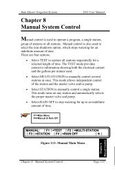
Table 1 - Electrical CalculationsValve solenoids are rated in either Amperes or VA. The term VA stands forVolt-Amps, which is obtained by multiplying the Amperes required by the 24 VACoperating voltage.Most modern solenoids require approximately .25 Ampere, which is equivalent to 6VA. This allows up to six solenoids to be energized at the same time.EXAMPLE: You are using a <strong>Master</strong> Valve and Pump; you have configured the systemto use the NO STACK option. This configuration would allow all four programs torun simultaneously, as depicted in Figure 2. <strong>Master</strong> Valve Wiring.Four programs (.25 A times 4) 1.00 Ampere<strong>Master</strong> Valve (.25 A times 1) .25 AmperePump using <strong>Rain</strong> <strong>Master</strong> RLY1 (.20 Amps) .20 AmpereTotal Current1.45 AmperesNOTE:This configuration would not exceed the 1.5 Amperes maximum allowablelimit.If higher current solenoids are used or if more than one solenoid is connected to anyone station output, caution should be used when operating in the NO STACK configurationmode.MECHANICAL SPECIFICATIONS• Heavy duty 18-gauge steel enclosure jet coated and powder coated to protect itfor indoor and outdoor environments.• Outdoor pedestal mount available for all models.• Two convenient sized enclosures for easy installation of field wires.• Outdoor pedestal mount available for all models.• Extra heavy-duty lightning and surge protected models available for areaswhere lightning is a concern.Shipping Weight:Dimensions:14 pounds13.25 inches Wide x 12.1 inches High x 4.3 inches DeepDOCUMENTATION• RME SENTAR <strong>II</strong> User <strong>Manual</strong> - RMIS part number 500043• RME SENTAR <strong>II</strong> Quick Reference Guide - RMIS part number 500065• Grounding Instructions (Option)• Multiple <strong>Control</strong>ler Installation Instructions RMIS Technical Bulletin 018 (Option)6
MOUNTING AND INSTALLATIONCONTROLLER PLACEMENTMOUNTING &INSTALLATIONWARNING: Do not drill holes in the controller's case. It has all the holes necessaryfor mounting it on a wall or pedestal. Drilling holes in the unit will cause metal chipsto mix with the electronics and this will cause the unit to malfunction. If, for somereason, it is absolutely necessary to drill additional holes in the unit, carefully removeall the electronics prior to doing so.<strong>Control</strong>lers are suitable for indoor/outdoor environment. It is lockable, dust-free andrain resistant. Outdoors the controller should be placed in a shaded and dryenvironment not subject to direct sprinkler spray or continuous heavy moisture.Additionally, a pedestal (PED 1) is available for outdoor controllers; contact your <strong>Rain</strong><strong>Master</strong> distributor.MOUNTING THE CONTROLLER1. On an upright, flat and secure surface, place the mounting bracket at eye leveland fasten securely.2. Mate the bracket on the back of the controller to the mounted bracket and hangthe controller.3. Secure the bottom of the controller by placing a screw through the hole locatedin its back wall at bottom center.CONTROLLER CONNECTIONS – AC POWER1. Refer to Figure 1 - Power and Field Wiring.2. Mount controller.3. Place <strong>Rain</strong> Switch in “No Watering” position.4. Remove lower panel.5. Using #10-gauge or heavier copper wire, connect ground screw to ground rod orgrounded water pipe using a ground rod clamp. The wire should be as short aspossible with no sharp bends or kinks. If multiple controllers are being installedin the same location, use a ground rod for each and contact the factory for theRMIS pamphlet on proper ground ing techniques.6. Thread condulet onto transformer.7. Connect supply line grounded conduit to condulet.8. Connect 120 V 50/60Hz supply line to transformer wires within theconduletInstall gasket and cover onto condulet with 2 screws.9. Follow all appropriate electrical wiring codes.10. Replace the lower panel and place the <strong>Rain</strong> Switch in “Automatic Watering”position after field valve wiring is complete.7
FIGURE 1. POWER AND FIELD WIRINGELECTRICAL GROUNDING FOR THE CONTROLLERProper electrical grounding is required to ensure safety to you, as well as to protect thecontroller electronics in the event of electrical line surges or lightning. In areas wherelightning is a common occurrence, it is strongly recommended to use the RMESENTAR <strong>II</strong> model SE-T.Grounding Instructions1. Mount the controller as close as possible to the grounding rod, so that the #10grounding wire from the controller to the ground rod is as short as possible.Ensure the grounding wire is free of nicks and bends.2. Use a grounding rod clamp to secure grounding wire to grounding rod. Be sureall surfaces are clean of oxides and dirt, and that all connections are solid andsecure.3. In areas of very dry soil or sand, it may be necessary to "Dope" the groundingrod. Contact your <strong>Rain</strong> <strong>Master</strong> distributor or <strong>Rain</strong> <strong>Master</strong> for grounding pamphlet, “RMIS Grounding”.4. Should the 8' grounding rod not penetrate completely into the soil it is acceptable to put it into the ground on a slight angle. It is important that the rod be afull 8' into the ground, with only enough of the rod showing to clamp the wireon. Should other grounding installation requirements be necessary, contact yourdistributor or <strong>Rain</strong> <strong>Master</strong>.Note: It is important to check the resistance periodically to ensure it is notgreater than 10 ohms. Contact your <strong>Rain</strong> <strong>Master</strong> Distributor for details.8
CONTROLLER CONNECTIONS – VALVES AND FIELD WIRINGThe controller utilizes quick disconnects and color coded wires. The wires are 24"long and each end must be stripped and attached to the corresponding field wire.RME SENTAR <strong>II</strong> ST and ST-T model controllers come equipped with terminals towhich the field wires are directly connected. Unused wires should be taped off toprevent shorting.The station numbers are labeled just above the quick disconnects behind the lowerpanel of the controller. Simply match the station's wire to the appropriate field wire.Note that the controller's COMMON wire is WHITE and the MASTERVALVE/PUMP is BLACK.Should it be necessary to detach the Quick Disconnect blocks from the printed circuitboard, hold the plastic assembly and pull down gently but firmly.Note: When reattaching the Quick Disconnect, be careful to make sure that the lip atthe top of the plastic connector is facing you as you push the connector onto thepins. Additionally, be sure to match the Quick Disconnect blocks with the corresponding color as labeled on the bottom of the printed circuit board.MASTER VALVE AND PUMP WIRING OPTIONSThe RME SENTAR <strong>II</strong> provides a variety of control options when selecting a <strong>Master</strong>Valve and Pump. Because the Pump and <strong>Master</strong> Valve can be assigned to any program,and the <strong>Master</strong> Valve can be either a Normally Open or Normally Closedconfiguration, virtually any system can be accommodated. For example, drip programsmay be setup in one or more programs which don’t use the Pump, while large rotorsmay be in a pump defined program. The following table summarizes the optionswhich are available, the installation diagrams required to achieve these options, andthe corresponding setup (programming of the RME SENTAR <strong>II</strong> using the SETUPkey). For detailed information on SETUP, please refer to ADVANCED SETUPPROGRAMMING beginning on page 47.<strong>Master</strong> Valve and Pump Wiring Options MatrixOption NormallyClosedMV1*2*3456✓✓✓———NormallyOpen MV———✓✓✓PumpUsedNeverAlwaysSometimeNeverAlwaysSometimeReferenceWiringFigure23 or 45255SETUPMV Usageper Program*No setup programming required (factory default settings).SETUPMVTypeNote: Although Option 2 shows that a pump is in the system, the setup programming indicates that the pump should not be programmed. This preservesStation 1 as a station output.91, 2, 3, 41, 2, 3, 41, 2, 3, 41, 2, 3, 41, 2, 3, 41, 2, 3, 4NCNCNCNONONOSETUPPump Usageper ProgramNoneNoneAs NeededNone1, 2, 3, 4As Needed
ELECTRICAL CONNECTIONS FOR A MASTER VALVEThe RME SENTAR <strong>II</strong> allows you to setup the <strong>Master</strong> Valve (MV) output as either aNormally Open or Normally Closed configuration. When used in the NormallyClosed mode, the <strong>Master</strong> Valve line is a source of 24 VAC power. It is activewhenever any station in the controller is on. For Normally Open <strong>Master</strong> Valves, thecontroller supplies 24 VAC only when either a Main Line Fault or Unscheduled FlowFault occurs.Normally Closed <strong>Master</strong> Valve OperationIf you have a <strong>Master</strong> Valve which requires activation to open, and no pump, connectthe <strong>Master</strong> Valve solenoid to the MV and Valve Common terminals as shown inFigure 2. If more than one controller is going to control the <strong>Master</strong> Valve, the<strong>Control</strong>ler must be isolated from each other. Contact RMIS for the pamphlet on“Multiple <strong>Control</strong>ler Installations”. During setup, select the NC (Normally Closed)Valve type for all programs (1, 2, 3, 4).RAIN FLOW ETFIGURE 2. MASTER VALVE WIRING (EITHER NORMALLY OPEN OR NORMALLY CLOSED)Simultaneous Normally Closed <strong>Master</strong> Valve and Pump OperationIf you have a <strong>Master</strong> Valve which requires activation to open, and a pump which isalways needed whenever irrigating, connect both the <strong>Master</strong> Valve solenoid and pumpstarter to the MV and Valve Common terminals as shown in Figure 3. If the pumpstarter operates on 24 volts AC and the combination of the <strong>Master</strong> Valve Solenoid andPump Starter require more than 1 amp, you will need an isolation relay (<strong>Rain</strong> <strong>Master</strong>part: RLY1 or equivalent) and an additional source of 24 VAC (see Figure 4). Duringsetup, select the NC Valve type for all programs which require the <strong>Master</strong> Valve andPump. DO NOT select pump operation.If the pump starter requires 120 VAC, you will also need an isolation relay (RLY1).If more than one controller is going to control the <strong>Master</strong> Valve and pump, thecontroller must be isolated from each other. Contact RMIS for the pamphlet on“Multiple <strong>Control</strong>ler Installations.”10
J12J4 J5 J6RAIN FLOW ETYELLOWBLACKTOTRANSFORMERYELLOWCOMMONMASTER VALVEPUMPFIGURE 3. SIMULTANEOUS NORMALLY CLOSED MASTER VALVE AND PUMPJ12J4 J5 J6RAIN FLOW ETYELLOWTOTRANSFORMERYELLOWBLACKWHITE1324 VACCOILRLY142MASTER VALVEPUMPFIGURE 4. SIMULTANEOUS NORMALLY CLOSED MASTER VALVE AND PUMPCONNECTION WITH ISOLATION RELAY11
Independent Normally Closed <strong>Master</strong> Valve and Pump OperationIf you have a <strong>Master</strong> Valve which requires activation to open, and a pump which issometimes needed when irrigating, connect the <strong>Master</strong> Valve Solenoid to the MV andValve Common terminals and the pump starter to Station 1 as shown in Figure 5. Ifthe pump starter DOES NOT operate on 24 VAC or the combination of the <strong>Master</strong>Valve Solenoid and pump starter require more than 1 Amp, you will need an isolationrelay (<strong>Rain</strong> <strong>Master</strong> part: RLY1 or equivalent) as shown. During SETUP, select the NC(Normally Closed) Valve type for all programs which require the <strong>Master</strong> Valve andselect Pump Operation for all programs which require it.If more than one controller is going to control the <strong>Master</strong> Valve or pump, thecontrollers must be isolated from each other. Contact RMIS for the pamphlet onmultiple controller installations.J12J4 J5 J6RAIN RAIN FLOW FLOW ET ETYELLOWTOTRANSFORMERYELLOWWHITETOSTATIONS(1-6)BLACK1324 VACCOILRLY142MASTERVALVEPUMPFIGURE 5. INDEPENDENT NORMALLY CLOSED MASTER VALVE AND/OR PUMPCONNECTION WITH ISOLATION RELAYNormally Open <strong>Master</strong> ValveIf you have a <strong>Master</strong> Valve which is always open until energized, connect thesolenoid to the MV and Valve Common terminals as shown in Figure 2.During setup, select valve type NO (Normally Open). The <strong>Master</strong> Valve willonly be activated when the controller detects a Main Line Break orUnscheduled Flow condition. In this case, a fault condition will exist untilmanually cleared.12
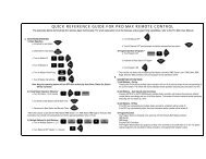
Normally Open <strong>Master</strong> Valve and Pump OperationIf you have a <strong>Master</strong> Valve which is always open until energized and a pump, connectthe solenoid to the MV and Valve Common terminals and the Pump to Station 1 asshown in Figure 6. During setup, select valve type NO (Normally Open). The <strong>Master</strong>Valve will only be activated when the controller detects a Main Line Break orUnscheduled Flow condition. In this case, a fault condition will exist until manuallycleared. Also during Setup, assign which programs (1-4) require the pump to operate.J12J4 J5 J6RAIN FLOW ETYELLOWTOTRANSFORMERYELLOWWHITETOSTATIONS(1-6)BLACKMASTERVALVEPUMPFIGURE 6. NORMALLY OPEN MASTER VALVE AND PUMPFLOW SENSOR INSTALLATIONRefer to Figure 7. Install the Flow Sensor in the Main Line as shown, making sure thatthere are at least 10 pipe diameters upstream and 5 pipe diameters downstream of thesensor from any valve, reducer, elbow, or other obstruction or device which may causeturbulence in the water flow. Observe the proper direction of flow according to theflow arrow on the sensor. Install a valve box around the sensor and make the electricalconnections inside the box. Use waterproof nuts over the splices.The use of <strong>Rain</strong> <strong>Master</strong> EV-CAB-SEN or other shielded cable is required to ensureproper operation. Polarity must be observed when connecting the sensor to the controller.13
RMECONTROLLERBOARDJ12J4SPLICE WIRES WITH THE PROVIDED WATERPROOF TYPE CONNECTORSVALVEBOX34WHTBLKBLACKWHITEEV-CAB-SEN CABLEDIRECTION OF FLOW10 PIPE DIAMETERSDIMENSION ‘A’FLOWSENSOR5 PIPE DIAMETERSDIMENSION ‘B’NO VALVES, REDUCERS,OR ELBOWS IN THIS AREAFIGURE 7. TYPICAL CONNECTIONS FOR FLOW SENSORUpon completion of the physical installation of the flow sensor, complete the wiring connectionfrom the flow sensor to the SENTAR <strong>II</strong> controller by following the procedure below.1. TURN THE POWER OFF AT THE CONTROLLER2. At the Flow Sensor:Connect the BLACK wire of the Flow Sensor to the BLACK wire of the“EV-CAB-SEN”, sensor cable.Connect the WHITE wire of the Flow Sensor to the WHITE wire of the“EV-CAB-SEN”, sensor cable.*Use the weatherproof connectors provided with the Flow Sensor to make the splice.3. At the controller:Connect BLACK wire of “EV-CAB-SEN” to “FLOW-” of the RME SENTAR <strong>II</strong> (pin #4)Connect WHITE wire of “EV-CAB-SEN” to “FLOW+” of the RME SENTAR <strong>II</strong> (pin #3)4. Turn POWER ON at the <strong>Control</strong>ler.5. Set the pipe size for the Flow Sensor at the controller based on the type and size of the FlowSensor installed.SENSOR WIRINGMost sensors, either <strong>Rain</strong> or Moisture type, are generally 2 or 3 wire.The 2 wire sensors are connected to pin 1 and 2 on the sensor connector block(See Figure 8).J12 J4 J51 2 3 4 5 6RAINSENSORINPUT (SILVER)24VAC (COPPER)– (BLK)+ (WHT)FLOWFIGURE 8. SENSOR WIRING14
TAPPING WIRES TO LOCATE VALVES IN THE FIELDDON'T – turn a station on and tap a wire to the controller's station terminal/wire tosee what valve in the field is connected to it. This is damaging to both mechanicaland solid state controllers and will cause the controller to go into a field wire faultdetection mode. The simple method shown below is safe and will work for both typesof controllers.1. Use <strong>Manual</strong> Station to turn on Station 1, perhaps for 1 hour.2. Flip the <strong>Rain</strong> Switch to the “No Watering” position.3. Touch the wire from the unknown field valve to the controller's Station 1terminal/wire.4. Flip the <strong>Rain</strong> Switch to the “Automatic Watering” position and the valve on thatwire will be activated.5. When you know what valve it is, flip the <strong>Rain</strong> Switch off before removing thefield wire from the controller's station terminal/wire.6. Choose the next field wire and start the process over at Step 2.7. When all done, turn off Station 1.AC POWER FAILURESIn the event of an AC power failure, all irrigation stations are turned off and thedisplay goes blank. The RME SENTAR <strong>II</strong> controller is equipped with non-volatileRAM (NVRAM) in order to protect user entered programs as well as important setupinformation during power loss.This data will be retained for an indefinite period of time regardless of the length ofthe power outage. Additionally, your RME SENTAR <strong>II</strong> is also able to maintain thetime and date for a period of up to 30 days (continuous) without the use of any typeof battery. If the power is off for longer than 30 days, the user will be notified by aflashing time display, when power is reestablished. The correct time can then bere-entered using the SETUP function.Regardless of the number of power failures, the date and time will be maintained forup to 30 days.In the event that a program is executing or a scheduled start time is missed when apower failure happens, the controller will intelligently resume execution where itwould have been if the outage had not occurred. The RME SENTAR <strong>II</strong> will completeits program execution preserving the original water window.REMOTE CONTROL CAPABILITYAll <strong>Rain</strong> <strong>Master</strong> controllers feature patented built-in remote control capability whichallows you to operate the controller for a distance of 1 mile in congested areas via ahand held transmitter. Consult the Remote <strong>Manual</strong> for operating instructions.Neverconnect anything but a <strong>Rain</strong> <strong>Master</strong> remote control receiver to the controller's frontpanel remote control connector or damage will result. Connecting to any other remotecontrol device to any portion of the <strong>Rain</strong> <strong>Master</strong> controller will void all warranties andmay cause damage.15
THIS PAGE INTENTIONALLY LEFT BLANK.16
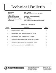
KEY OPERATIONSThere are three types of keys on the face of the controller. The diagram below showsthe location of each group of keys. A detailed explanation of each key is given on thefollowing pages.KEYOPERATIONS17
FUNCTION KEYSThese keys (tan color) perform a specific function.SETUPAllows you to perform the following setups:- Program a <strong>Master</strong> Valve to any or all programs.- Program the type of <strong>Master</strong> Valve to be either aNormally Closed <strong>Master</strong> Valve or a Normally Open<strong>Master</strong> Valve.- Program a Pump to any or all programs.- Program Stacking or Non-Stacking of programs- Program time delay between station(s) from 0 - 255seconds (4 mins. 15 secs.)- Program a Security Code- Program a sensor to any or all programs- Program audible alarm warning- Program any or all programs to be either a Cycle andSoak program or not.- Program the Flow Sensor features to be enabled ornot.- Program the Pipe size for the Flow Sensor to beeither 1, 1.25, 1.5, 2, 3 or 4 inches.- Program the main line flow limit, which is the maximum flow when the controller is watering, to befrom 01 to 999 GPM.- Program the unscheduled flow limit, which is themaximum flow when the controller is not watering,to be from 0 to 999 GPM.- Program the flow check delay, which is the amountof time the controller waits after any station changesbefore any flow limits are checked, to be from 1minute to 6 minutes.- Clear the total accumulated gallons and look at thetotal accumulated gallons.- Program the flow percentage, which is a percentagethat will be used to adjust all station flow limits, tobe from 5% to 80%.- Program a station flow limit for each station, from 0to 500 GPM, either by explicitly setting a limit foreach station or by running a watering profile duringwhich the controller will LEARN each station'supper flow limit.SET TIMEAllows you to set the current time and date inthe controller.PROGRAMAllows you to select the program that is required(from 1 - 4).WATERDAYSIs used to select the water days that the program is tooperate on.18
STATIONSSTARTTIMESQUICKSTATIONSWATER%BUDGETREVIEWMANUALIs used to select the stations and runtimes in each program.If the program is specified to be a cycle and soak one, viaSETUP, then it is also used to set the maximum time andsoak time for each station.Is used to select the start time(s) for each program (up to 5per program).Is used when a block of stations with the same runtime isbeing programmed. If the program is specified to be a Cycleand Soak one, via SETUP, then it is used to program a blockof stations with the same runtime, maximum time andsoak time.Is used to change the runtimes (from 0% to 300%)for each station on a percentage basis by program.Is used to review all program information on each programin the controller. It is also used to look at the total gallonsused.Is used to manually turn on a program, station, or to checkall stations. Additional uses include locking and unlockingthe controller once a security access code has been enteredvia SETUP, and advancing to the next station when executing a program.SKIP DAYSIs used to select the Skip By Day method of WaterDays entry.EXECUTE KEYSThese keys will execute the function that has been selected to be programmed.ENTERAll DATA KEY input must be followed by the ENTER keyto be accepted by the controller.CLEARAllows you to clear a selected function out of a program.This key will also put the controller in the programmablerain mode.QUITIs used to complete a function after it has been executedand will return the controller to the automatic mode.This key may be pressed to exit any function.19
DATA KEYSThese keys are used to select days of the week when entering time and day, and areused to select numbers such as runtimes, delay times etc.The number 1 key is also a toggle ON/OFF key when used in the Setup mode.SUN1MON2WED4TUE3THU FRI5 6SAT7 8 9AMPM020
WORDS AND TERMS USED IN THE DISPLAYIPROGRAMHELLO= Hello will be displayed when the controlleris powered up for the very first time.When Hello is displayed there are NO userprograms in the controller. If left in theHELLO mode the controller will begin towater every station for 10 minutes, starting 6hours after the HELLO has been displayed.The 10 minute per station watering shallrepeat every 24 hours.Hitting any key exits HELLO mode,and removes the default watering program.UNDER SETUPM VIPROGRAMIPROGRAMIPROGRAMTYPE - NCTYPE - NOPUMPIPROGRAMSTACKIPROGRAM= <strong>Master</strong> Valve.= <strong>Master</strong> Valve type is Normally Closed (NC).= <strong>Master</strong> Valve type is Normally Open (NO).= Pump.= Ensures that programs run one after another,even if their start times overlap.NO STACKIPROGRAMDELAY 000IPROGRAMCODE 00 00IPROGRAMS N S RIPROGRAM= Run programs at their scheduled start times.In the event that start times overlap, multipleprograms will run concurrently.= Time delay between stations (0-255 seconds).= Access or Security Code.= Sensor input.21WORDS &TERMS
ALARM ON / OFFIPROGRAMSOAKIPROGRAMFLOW ON / OFFIPROGRAMPIPE 1 . 0 0IPROGRAMPIPE 1 . 2 5IPROGRAMPIPE 1 . 5 0IPROGRAMPIPE 2 . 0 0IPROGRAMPIPE 3 . 0 0IPROGRAMPIPE 4 . 0 0IPROGRAMPIPE OTHERIPROGRAMMAIN SOOIPROGRAMUNSCH 200IPROGRAMF DELAY 2IPROGRAMTOTAL . . .GALLONS . . .1234IPROGRAMIPROGRAMPERCENT 20= An audible beep will be given off (o r not) ifa fault is detected.= Cycle and Soak.= Flow sensor features are enabled (or disabled).= Flow sensor is standard 1" pipe.= Flow sensor is standard 1.25" pipe.= Flow sensor is standard 1.5" pipe.= Flow sensor is standard 2" pipe.= Flow sensor is standard 3" pipe.= Flow sensor is standard 4" pipe.= Reserved for <strong>Rain</strong> <strong>Master</strong> use only.= Main line flow limit (in GPM).= Unscheduled flow limit (in GPM).= Flow check delay (in minutes).= The total gallons used since the last time itwas cleared. (Display flashes “TOTAL”,“GALLONS”, then number.)= Percentage adjust to all station upperflow limits.22
LIMITSIPROGRAM1 0 0 G P MIPROGRAM= Upper flow limits for stations.=This display appears in three differentinstances (if flow sensing has been enabled).1. Flashes when an automatic programis executing.2. In <strong>Manual</strong> System Check/Syringe Cycle.3. Displays measured flow while the controlleris going through watering profile toLEARN station upper flow limits.1 - 2 0 0IPROGRAM= Upper flow limit for a station in GPM.(Example shows station 1 upper flow limit of200 GPM.)1 2 3 2 0 0IPROGRAM= Measured flow (on left) and upper flow limitfor the station (on right).OTHER TERMSLOCKEDIPROGRAM= A Security Code has been entered andenabled. Requires reentry of the Access Codeto unlock.IPROGRAMLO -= Low, used in Quick Stations function.IPROGRAMIPROGRAMIPROGRAMIPROGRAMHI -L M - 0 : 0 0RAIN OFFRUN TIME= High, used in Quick Stations function.= Length, used in station function and inQuick Station function.= <strong>Control</strong>ler is in <strong>Rain</strong> shut-down, used withthe manual <strong>Rain</strong> Switch.= Momentarily comes up before the runtimeis to be entered in the station feature andquick station feature, if the program is Cycleand Soak.23
IPROGRAMIPROGRAMMAX TIMESOAK TIME= Momentarily comes up before the maximum timeis to be entered in the station feature and quickstation feature, if the program is Cycle and Soak.= Momentarily comes up before the soak time isto be entered in the station feature and quickstation feature, if the program is Cycle and Soak.IPROGRAMLFT - 00= Left, used in Skip Days function.IPROGRAMIPROGRAMO KIPROGRAMIPROGRAMOFFP OR SNO= No, used anytime to indicate invalid info.= Off, indicates the controller is off and willnot water.= Okay, indicates an acceptance of an option.= Program (P) or station (S) used in <strong>Manual</strong> function.PROG-IPROGRAMIPROGRAMIPROGRAMPT - 1 0 0SD -SET TIMEIPROGRAMSTA -IPROGRAMIPROGRAMIPROGRAMSTATIONS2 W DAY= Program, used in Program function.= Percentage, used in Percentage function.= Skip days, (SD) used in the Skip Days function.= Set time, used in the Set Time function.= Station, used in the Stations function.= Stations, used in the Review feature.= Water days, used in the Water Days function.24
IPROGRAMRAIN - 2= The controller has been placed in the programmable <strong>Rain</strong> Mode and will not water for 2 days. The<strong>Control</strong>ler indicates the remaining days (1-7)before next water.IPROGRAMSNSR - WET= The <strong>Rain</strong> Sensor associated with this program is ina wet condition, used in the Review feature.IPROGRAM* IPROGRAMSNSR - DRY04 : 23= The <strong>Rain</strong> Sensor associated with this program isreading a dry condition.= A program is running in the Automatic Modebut no stations are watering because the rainsensor is enabled and a wet condition exists.CHECKIPROGRAMWAITIPROGRAM= In <strong>Manual</strong> System Check/Syringe Cycle and theflow sensor features are not enabled.= Flashes at about 1 second rate during power up(only if power up takes a long time; power up usually takes several seconds but under very unusualcircumstances can take several minutes).FAULT . . . PRESS . . .REVIEWIPROGRAMWIRINGIPROGRAMIPROGRAMFLOW STA= Either an overcurrent or short circuit has occurredon one or more stations, field wires or valve solenoids or a flow limit violation has occurred. PressREVIEW for more information.= Shown when REVIEW is pressed during a faultcondition and the problem is an overcurrent orshort circuit in the station field wiring. The faultystation(s) will be shown in the LED lights.= Shown when REVIEW is pressed during a faultcondition and the problem is a station upper flowlimit violation. The faulty station(s) will be shownin the LED lights. Subsequent press of theREVIEW key shows the measured flow in GPMat the time the fault was detected.25
IPROGRAMIPROGRAMFLOW UNFLOW MAIN= Shown when REVIEW is pressed during a faultcondition and the problem is an unscheduled flowlimit violation. Subsequent press of the REVIEWkey shows the measured flow in GPM at the timethe fault was detected.= Shown when REVIEW is pressed during a faultcondition and the problem is a main line flowlimit violation. Subsequent press of the REVIEWkey shows the measured flow in GPM at the timethe fault was detected.AUTOMATIC MODEThe controller is in the Automatic Mode whenever the time is displayed, and the dayof the week indicator light is lit.PressingQUITwill always return the controller to the Automatic Mode.When a program is watering in the Automatic Mode, the station and program numberwill be displayed as a convenience. If the controller has been setup to enable flow sensing,the measured flow (GPM) will alternately appear in the display at a 1 second rate.*A in place of the program number, indicates a program is running but all stationsare off because the rain sensor is enabled and a wet condition exists.To advance to the next station in a program when a program is already watering,Press:MANUALTo stop and cancel a program that is watering,Press:CLEARQUITThe controller returns to the Automatic Mode.RAIN MODEThe controller has a <strong>Rain</strong> Switch. The switch MUST BE in the "AutomaticWatering" position anytime watering is desired. In the "Automatic Watering"position, watering WILL occur if the controller is programmed to do so.The switch should be placed in the "No Watering" position when no watering isdesired, such as when it is raining, etc. In the "No Watering" position, no wateringwill occur and “RAIN OFF” will appear in the display to indicate that all programsare inhibited from watering. The user's program will not be disturbed26
PROGRAMMABLE RAINThis method is used in place of the <strong>Rain</strong> Switch when you know how many days youwant the controller to stay off. It allows you to select the number of days, from 1-7,that the controller will stay in the programmable <strong>Rain</strong> Mode after which it will returnto the Automatic Mode by itself.EXAMPLE: You wish the controller to stay off for 6 days,Press:CLEARFRI6 ENTERThe controller will diplayRAIN - 6IPROGRAMEach night at midnight the controller will deduct one day until it finally returns to theAutomatic Mode.Note:No watering will occur when it goes back to the Automatic Mode if you havealso placed the <strong>Rain</strong> Switch in the “No Watering” position.27
THIS PAGE INTENTIONALLY LEFT BLANK.28
QUICK AND BASIC PROGRAMMINGBefore the controller will operate, some basic information must be programmed.1. Set the Time of day and Date for the controller.2. Establish a valid watering program:a. Choose the program number you wish to work with (1-4).b. Set the Water Days.c. Set the Stations and the Watering Time for each station.d. Set the Start Time(s) the program will begin to water on the chosen days.SET TIMEThis is used to set the current time of day and the current date.EXAMPLE 1: The time is 2:00 PM, Saturday, June 16, 2001.Press:The controller returns to the Automatic Mode.EXAMPLE 2: The time is 10:35 AM, Tuesday, December 12, 2002Press:SET TIMESET TIMEMONAM2 0 0ENTERPM0SUNFRI6SUN FRI1 6 0TUETHU1 0 3 5 ENTERSUN1 ENTERQUICK & BASICPROGRAMMINGSUN MON SUN MONMON1 2 12 ENTERThe controller returns to the Automatic Mode.PROGRAMThis is used to select the program(s) you wish to work with. Once selected, you neednot change the program # until you wish to program or review information in adifferent program. There are 4 programs available for your use. They are referred toas 1, 2, 3, and 4. If desired, it is also possible to select and clear ALL information in aprogram using this function.PROGRAM SELECTIONSelect the program you wish to work with, either 1, 2, 3, or 4. While programmingother functions, the selected program number is displayed as a convenience.EXAMPLE: You wish to work with Program 2,2 0Press:PROGRAMMON2 ENTERThe controller returns to the Automatic Mode.29
PROGRAM CLEARIf desired, it is possible to both select and clear all information in a program.EXAMPLE: You wish to select and clear all information in Program 1,Press:PROGRAMSUN1 CLEARThe controller returns to the Automatic Mode.WATERING DAY SELECTIONSWatering days for Programs 1, 2, 3 and 4, may be set on a 7 day week or a Skip Daysmode. Although you cannot do both within the same program, each program may beset to either mode.EXAMPLE: Program 1 may be on a 7 day weekly basis but Program 2 might be ona skip days basis.WATER DAYSTo select watering days based on a 7 day week. Watering will occur on the daysselected each and every week. Selected days are shown in the top display. TheProgram # is shown in the display as a convenience.EXAMPLE: You wish to water on Sunday, Wednesday and Friday,Press:WATERDAYSSUN1 ENTERThe controller returns to the Automatic Mode.WED4 ENTEREXAMPLE: To remove a watering day, such as Sunday,FRI6 ENTER QUITPress:Press:WATERDAYSQUITSUN1 CLEARThe controller returns to the Automatic Mode.EXAMPLE: To review Water Days information,Press:Press:WATERDAYSQUIT(An LED light will light up for everyday that watering is to occur.)The controller returns to the Automatic Mode.30
SKIP DAYSThis is used to establish the number of days between watering, from 1 to 30, and howmany days are left till the first watering will begin. If information has been entered inthe past, the Skip Day number will be shown in the display. The Program # is shownin the display as a convenience.Note: 0 days left means the watering day is today.Note: By using the Skip Days mode you can have a program water every 2nd, 3rd,4th,... or 30th day as may be desired.EXAMPLE: You wish to skip 2 days and water every third day, and to start it 4 daysfrom now,Press:SKIP DAYSMON2 ENTERThe controller returns to the Automatic Mode.EXAMPLE: To clear all Skip Days information,WED4 ENTERPress:SKIP DAYS CLEAR QUITThe controller returns to the Automatic Mode.EXAMPLE: To review Skip Days information,Press:SKIP DAYSand the Skip Day number is shown,Press:Press:ENTERQUIT(the number of days left beforethe next watering is shown.)The controller returns to the Automatic Mode.STATIONS AND WATERING TIMESAny station may be placed in any program. Stations may be placed in more than oneprogram at a time if desired. Within each program, each station can have a differentruntime. Each program can individually be selected (via SETUP) to be either aconventional program or a Cycle and Soak program. Depending upon the selection,the RME SENTAR <strong>II</strong> will prompt for the appropriate information whenever theSTATION key is pressed.31
STATIONS (for a conventional program)This is used to select the stations and set the runtime for each station. After enteringthe desired station #, the runtime for the station is then entered. Percentage is brieflyshown at the beginning to remind you of its setting. Selected stations are shown inthe top display. The Program # is shown in the display as a convenience.EXAMPLE: You wish to set Station 1 for 10 mins., Station 2 for 10 mins., Station 6for 1 hr. and 15 mins. and Station 7 for 8 mins,Press:STATIONSSUNSUN1 ENTER 1 0 ENTERMON2FRI6ENTERENTERSUN1SUNSUN110ENTERTHU5ENTERSAT7ENTER8ENTERPress:QUITThe controller returns to the Automatic Mode.EXAMPLE: To clear a station and its runtime, such as Station 7,Press:STATIONSSAT7CLEARPress: QUITThe controller returns to the Automatic Mode.EXAMPLE: To review selected Stations information,Press:Press:STATIONSQUIT(An LED light will light up for everystation that has a valid runtime.)The controller returns to the Automatic Mode.EXAMPLE: To review the runtime of a station, such as Station 6,Press:STATIONSFRI6ENTER(the runtime length is displayed)Press:Press:ENTERQUITto leave the runtime as is and continue reviewing,The controller returns to the Automatic Mode.32
QUICK STATIONS (for a conventional program)This is used to rapidly program a block of stations which all have the same runtime.First the lowest station number is entered, then the highest and then the runtime.This length is applied to all the stations from the lowest through the highest. Selectedstations are shown in the top display. Percentage is briefly shown at the beginning toremind you of its setting. The Program # is shown in the display as a convenience.EXAMPLE: You wish to set all stations from 12 through 34 for 56 mins.Press:QUICKSTATIONSSUN1MON2 ENTER TUE3The controller returns to the Automatic Mode.CYCLE AND SOAKA Cycle and Soak program can be used to eliminate runoff. Runoff occurs wheneverthe precipitation rate of the irrigation system exceeds the percolation rate of the soil.The Cycle and Soak program allows each individual station to be programmed toeliminate the wasteful effect thereby maximizing water savings. In a conventionalprogram each station in the program will run for the full runtime and then the nextstation will run, etc.Note: To configure a program for Cycle and Soak operation, refer to the AdvancedSetup Programming for Cycle and Soak.In a Cycle and Soak program, in addition to the runtime, there are two other timesassociated with each station; the maximum watering time and the soak time. Themaximum watering time is the maximum time that the station can be on beforerunoff occurs. The soak time is the amount of time that the station must be off beforeit can come on again. This time allows the water to percolate into the root zone of theplant material. In a Cycle and Soak program the controller figures out a profile to runthe stations that minimizes the total watering time for the program and intelligentlyschedules stations to run while other stations are satisfying their soak times. At the endof the profile each station will have run for its full runtime but the runtime may notbe contiguous. For a particular profile, it may be that at times during the profile nostations will be on.WEDTHUFRI4 ENTER 5 6ENTERCycle and Soak Station ParametersParameter Minimum Maximum IncrementRuntime1 Min9 Hrs 59 Min1 MinMax Watering Time1 Min4 Hours1 MinSoakTime1 Min4 Hours1 Min33
STATIONS (for a Cycle and Soak program)This is used to select the stations and set the runtime, the maximum watering timeand the soak time for each station. After entering the desired station number, theruntime is entered followed by the maximum watering time, and finally the soak time.Percentage is briefly shown at the beginning to remind you of its setting. Thepercentage only applies to the runtime and not to the maximum watering time or soaktime. Selected stations are shown at the top of the display. The program number isshown in the display as a convenience.Note:If a pump is assigned to any program (via SETUP) then station 1 cannotbe selected as it is reserved for the pump.EXAMPLE: You wish to set Station 1 for a runtime of 1 hr and 5 mins., a maximumtime of 35 mins. and a soak time of 45 mins. and station 6 for a runtime of 2 hrs, a maximum time of 1 hr and a soak time of 20 mins. (Youmust have previously set, via SETUP, the program for which you areentering information, to a Cycle and Soak program.)Press:STATIONSSUN1 ENTER(controller will momentarily display “RUN TIME”)SUN1 0THU5 ENTER(controller will momentarily display “MAX TIME”)TUE3THU5ENTER(controller will momentarily display “SOAK TIME”)WED4THU5ENTERFRI6ENTER(controller will momentarily display “RUN TIME”)MON2 0 ENTER 0(controller will momentarily display “MAX TIME”)SUN1 0 ENTER 0(controller will momentarily display “SOAK TIME”)MON2 0 ENTERPress:QUITThe controller returns to Automatic Mode.Note: If the same station appears in multiple Cycle and Soak programs, only onevalue for the maximum time is allowed across programs. The same holdstrue for soak times.34
EXAMPLE: To clear a station and its runtime, such as Station 7,SATPress: STATIONS7 CLEARPress:QUITThe controller returns to the Automatic Mode.EXAMPLE: To review selected Stations information,Press:STATIONS(An LED light will light up for everystation that has a valid runtime.)Press:QUITThe controller returns to the Automatic Mode.EXAMPLE: To review the runtime, maximum time and soak time of a station suchas Station 6,Press:STATIONSFRI1 ENTER(the runtime is displayed)Press:Press:Press:ENTERENTERENTERto leave the runtime as is and continue reviewing,to leave the maximum time as is andcontinue reviewing,to leave the soak time as is and continue reviewing,Press:QUITThe controller returns to the Automatic Mode.QUICK STATIONS (for a Cycle and Soak program)This is used to rapidly program a block of stations which all have the same runtime,maximum watering time and soak time. First the lowest station number is entered andthen the highest and then the runtime and then the maximum watering time and thenthe soak time. Percentage is briefly shown at the beginning to remind you of itssetting. The percentage only applies to the runtime and not to the maximum wateringtime or soak time. Selected stations are shown at the top of the display. The programnumber is shown in the display as a convenience.Note: If a pump is assigned to any program (via SETUP) then Station 1 cannotbe selected as part of the block of stations as it is reserved for the pump.35
EXAMPLE: You wish to set all stations from 12 through 34 for a runtime of 1 hr and56 mins and maximum time of 20 mins and a soak time of 15mins. (Youmust have previously set, via SETUP, the program for which you areentering information, to a Cycle and Soak program.)Press:QUICKSTATIONSSUN1MON2 ENTERTUE3(controller will momentarily display “RUN TIME”)WED4 ENTERSUNTHU FRI51 6 ENTERMON2 0 ENTER(controller will momentarilydisplay “MAX TIME”)(controller will momentarilydisplay “SOAK TIME”)SUNTHU1 ENTER536The controller returns to the Automatic Mode.Note: The maximum time and/or soak time entered will be used for the stations in theblock for all Cycle and Soak programs and not just for the one being entered.PERCENTAGEThe Percentage function provides for simple water budgeting by providing an easymethod of increasing/decreasing the runtimes of ALL stations in a program with onesimple entry. It is particularly useful during abnormally dry, hot, cold or wet periods.The Percentage is set to 100 in all four programs by default, therefore, unless changed,each station in a program will run for 100% of its programmed time. Percentagemay be set from 0 to 300%, in increments as small as 1%, for Programs 1, 2, 3 and4 independently.For instance, setting the Percentage in a program to 161 will make the runtime of eachstation 1.61 times its programmed runtime. Setting the Percentage to 70 will makethe runtime 0.70 times its programmed runtime.Note:If Percentage is set to other than 100, the watering lengths of all stations ina program will be changed when you view them.Note: For a Cycle and Soak program the Percentage only applies to the runtimes andnot to the maximum watering times or soak times.
EXAMPLE: You wish to set a Percentage of 110 which will increase the wateringtimes of all stations in a program by 10%,SUN SUNPress: WATER%BUDGET 1 1 0 ENTERThe controller returns to the Automatic Mode.EXAMPLE: To clear Percentage,Press:WATER%BUDGET CLEAR QUITThe Percentage is reset to 100 and the controller returns to the Automatic Mode.EXAMPLE: To review Percentage,Press:WATER%BUDGETPress:QUITThe controller returns to the Automatic Mode.Note:Percent calculations which result in fractional portions of minutes will irri gatefor the precise time. For example, assume a 5 minute runtime with apercentage of 50%. This station will irrigate for 2 minutes and 30 seconds.START TIMES AND AUTOMATIC PROGRAMOVERLAP PROTECTIONThere are five start times available for each of Programs 1, 2, 3 and 4. They arereferred to as Start Time 1 – Start Time 5.Additionally, the controller allows you to select (via SETUP) whether programs will beallowed to run one at a time (Stack) or run concurrently (No Stack) in the event thatstart times overlap with one another. Using Stack operation the controller ensures thatonly one program (e.g. one station) is allowed to be turned on at one time regardlessof conflicting start times. The controller program(s) will wait for completion of thecurrently executing program before it will start the next program. The followingexamples describe Stack Operations:EXAMPLE 1: If Program 1 is one hour long, due to the stations and watering timesplaced in it, and you set three of its start times to 7:00 AM, the program will water three times - from 7:00 to 8:00, 8:00 to 9:00 and 9:00to 10:00 thereby providing two repeat cycles.EXAMPLE 2: If Program 1 was again one hour long and was set to start at 7:00 AMMon., and Program 3 was set to start at 7:30 AM on Mon. and Tue.,then on Mon. Program 3 would begin at 8:00AM , when Program 1ended, but on Tue. it would begin at 7:30 AM.37
The Stack operation ensures that you will always get the number of watering cyclesyou desire and at the same time your system will never be under-pressurized becausetwo programs are running simultaneously.Note: The controller is shipped with Stack active, however, it may be programmedso that multiple programs can be run simultaneously. See AdvancedSetup Programming.START TIMESThis is used to set the start time for a program. The Program # is shown in thedisplay as a convenience.EXAMPLE: You wish the program to start watering at 7:10 AM and 4:30 PM,Press:STARTTIMESSAT7SUN1 0 ENTER(The controller goesto Start Time 2.)WED TUEAM4 3 0ENTERPM(The controller goesto Start Time 3.)Press:QUITThe controller returns to the Automatic Mode.EXAMPLE: To review Start Times,Press:STARTTIMES(Start Time 1 is displayed).EXAMPLE: To review Start Time 2,Press:ENTERPress:QUITThe controller returns to the Automatic Mode.EXAMPLE: To clear a start time, such as Start Time 2,Press:STARTTIMES(Start Time 1 is displayed.)EXAMPLE: To get to Start Time 2,Press:ENTER(Start Time 2 is displayed.)EXAMPLE: To clear Start Time 2,Press:CLEARENTERThe controller returns to the Automatic Mode.38
REVIEWING PROGRAMS AND TOTALIZERA unique feature of the RME SENTAR <strong>II</strong> controller is its Review feature. At the pushof a key, all program information will be displayed. Successive pushes of the REVIEWkey cause the information to advance. Another way of reviewing information is topress and hold the REVIEW key. As the key is held the information will automaticallyadvance at a readable rate. Removing your finger causes the scrolling information tostop. Pressing QUIT at any time will return the controller to the Automatic Mode.The information for the programs will start with information for the program selected(via the PROGRAM function key) and continue until Program 4. For instance ifProgram 1 is the selected program then information in Program 1 will be displayedfirst, followed by Program 2, 3 and 4 and if Program 3 is the selected program theninformation in Program 3 will be displayed first, followed by Program 4.The information presented is as follows:1. The total watering time for the program (displayed with H [hours] and M [minutes]). This is the actual watering time and takes into account all factors including the percentage adjust, any delay between stations (set via SETUP) and anyadjustments needed because the program is a Cycle and Soak program. Thedisplayed value is rounded up; for example, a total time of 2 hours, 12 minutesand 14 seconds will be 2 hours and 13 minutes.2. If the flow feature was enabled (via SETUP), and Program 1 was the last selectedprogram, then TOTAL…GALLONS… will be displayed.Note:When using the Review function, the total gallons screen records andupdates measured gallons every 10 seconds. It can be used to check forunscheduled flow.3. If the <strong>Rain</strong> Sensor has been Enabled (via SETUP) for this program then:SNSR-WET or SNSR-DRY will be displayed.4. Start Times 1, 2, 3, 4 and 5 (displayed as START...TIME).5. Water Days (displayed as W DAY).6. Skip Days (displayed as SD) and the number of days left until the next watering(displayed as LFT).7. Percentage (displayed as PT).8. Stations and their actual runtimes (displayed as STATIONS). If the program is aCycle and Soak program (as selected via SETUP), the maximum watering timeand soak time will also be displayed for each station.Note:The runtime shown for each station is the programmed length and will notbe modified by the value you may have set for the percentage adjust function.39
EXAMPLE: You wish to review program 3 only,Press:PROGRAMTUE3ENTERPress:REVIEWContinue to press:Press:QUITThe controller returns to the Automatic mode.40
MANUALLY ACTIVATED FUNCTIONS WITH EXAMPLESThe <strong>Manual</strong> Mode offers four different features as described below:MANUAL PROGRAMThis is used to run a program - assuming stations are in the program.EXAMPLE: You wish to run Program 1,Press:MANUAL PROGRAM SUN1 ENTERThe controller returns to the Automatic Mode.(The display shows a 1 to indicateProgram 1 is running. The activestations are displayed as well as theelapsed station runtime.)EXAMPLE: To advance to the next station when the program is already watering,Press:MANUALEXAMPLE: To stop the watering program that is currently running,Press:CLEARQUITThe controller returns to the Automatic Mode.MANUAL STATIONThis is used to run a selected station for a specified time.MANUALFUNCTIONSEXAMPLE: You wish to run station 6 for 25 min,Press:MANUALSTATIONSMON2 ENTERMON2THU5 ENTER(The display shows station and watering time. As time elapses, watering time willcount down. When time ends, the station shuts off and the controller returns to theAutomatic Mode.)EXAMPLE: To stop the watering station,Press:QUITThe controller returns to the Automatic Mode.Note: If a pump is assigned to any program (via SETUP) then Station 1 is reservedfor the pump, but it can still be turned on manually by specifying Station 1.Note: If the <strong>Master</strong> Valve type is Normally Closed (as specified via SETUP) then the<strong>Master</strong> Valve will come on with the station. If the station being turned on is in41
any program that has a pump assigned to it (via SETUP) then the pump(Station 1 output) will come on with the station.MANUAL MASTER VALVEThis is used to run only the <strong>Master</strong> Valve for a selected time. The MV is designatedas Station 0.EXAMPLE: You wish to run the <strong>Master</strong> Valve for 4 min.,Press: MANUAL STATIONSTo stop:ENTER0WED4ENTERPress:QUITThe controller returns to the Automatic ModeMANUAL SYSTEM CHECK/SYRINGE CYCLEAs a convenience for "walk throughs" and service work, and to measure the flow rateon a station, the controller has a system check feature built in. This will run eachstation, from the first to the last, for a selectable time of 1 to 9 mins.EXAMPLE: To run a 3 min. System Check,TUEPress: MANUALDO NOT PRESS ENTER3If the flow features have been enabled (via SETUP) then the display will show thecurrent measured flow rate in GPM and count-down elapsed time during the CHECKmode. If the flow features are not enabled then only the count-down elapsed time willappear in the display.EXAMPLE: To advance one station at a time,Press:MANUALEXAMPLE: To stop the System Check,Press:CLEARQUITThe controller returns to the Automatic Mode.Caution: This mode sequentially runs every station in the controller. For exampleyou have a 24 station unit but only use 23 stations, it will still apply power for Station24 and while doing so will apply power to the <strong>Master</strong> Valve/Pump terminal. This42
could be a problem for a system when you are using the <strong>Master</strong> Valve output todrive a pump because during the period that Station 24 is activated, the pumpwill be pumping against a closed system. If the system uses a master valve, it willbe activated during the period that Station 24 is active and this could causeheating of the <strong>Master</strong> Valve's solenoid (if the valve depends on water flow to coolit). Therefore, if all stations are not used, cancel the System Check/Syringe cycleafter the last used station has watered.MONITORING STATION FLOWThere are three ways to observe the measured flow in gallons per minute (GPM):1. The measured flow is automatically displayed when the controller is in theautomatic mode and one or more programs are operating.2. When a manual system check is performed, the flow is shown for each station. (Refer to MANUAL SYSTEM CHECK for details.)3. When in the SETUP function, measured flow can be observed on a per station basis when utilizing the LIMITS subfunction. (Refer to the LIMITSSETUP feature in the ADVANCED SETUP PROGRAMMING sectionfor more details.)FAULT DETECTION OVERVIEWThe RME SENTAR <strong>II</strong> has the ability to detect and take corrective action for anumber of field related failure conditions. The operator is informed of any faultcondition when the display alternates with the following words:FAULT.......... PRESS ......... REVIEWIn addition to the display indication, the controller will chirp with an audible alarmonce every six seconds signifying a fault occurrence.Note: The audible chirp may be disabled via the SETUP function.Pressing the REVIEW key reveals the specific fault type and momentarily suspends theaudible chirp.WIRINGIPROGRAM= The problem is a field wiring short circuit on a station. The station lights illuminate to show which station(s) were faulty.IPROGRAMFLOW MAIN= The problem is a main line flow limit violation.Pressing the REVIEW key again reveals the measuredGPM at the time the fault occurred.43
IPROGRAMIPROGRAMFLOW UNFLOW STA= The problem is an unscheduled flow limit violation.Pressing the REVIEW key again reveals the measuredGPM at the time the fault occurred.= The problem is a station upper flow limit violation.The station lights illuminate to show which station(s)are involved. Pressing the REVIEW key again revealsthe measured GPM at the time the fault occurred.Whenever a specific fault is displayed it can be cleared by pressing the CLEAR key.Alternatively, if CLEAR is not hit, the QUIT key will return the controller to theAutomatic Mode without clearing the fault condition.Refer to the fault type(s) defined below for specific information.WIRING FAULTThe RME SENTAR <strong>II</strong> has been equipped to detect station short circuits which mayoccur due to improper field wiring or faulty valve solenoids. In the event a stationdraws excessive electrical current, the following action occurs:• The offending station will be immediately turned off.• The next scheduled station of the program will be started.• FAULT…PRESS…REVIEW…appears in the display.• The controller will continue to execute programs, however, any faultedstation(s) will not be turned on again.Note: If multiple stations are on simultaneously, and the controller detects anovercurrent fault, all running stations will be diagnosed as faulty.Note: If a short circuit occurs at the normally closed <strong>Master</strong> Valve and the programhas been setup to use a <strong>Master</strong> Valve, the controller will successively condemnall remaining stations in the program. Upon reviewing the fault, all stations ofthe program shall illuminate, indicating that the problem appears at the<strong>Master</strong> Valve.User Action:1. Excessive station current may be due to an inadvertent direct connection betweenthe station wire and the common wire.2. Check for exposed wiring in a flooded valve box.3. Check for a faulty valve solenoid.4. When corrective action has completed, the fault should be cleared.FLOW MAIN FAULTThe main line flow limit for the controller has been exceeded.44
• All present irrigation programs are terminated.• FAULT…PRESS…REVIEW…appears in the display.• If the <strong>Master</strong> Valve for the controller has been setup as a Normally Open(NO) <strong>Master</strong> Valve, then this terminal will be energized with 24 VAC(<strong>Master</strong> Valve is closed).• All scheduled start times for future programs will be ignored (no programswill start).• The controller remains in this state until the fault is cleared by you.User Action:1. Inspect the main line as well as major branches for failure.2. Examine the main line limits to ensure they have been correctly established. Ifthe controller has been setup for No Stack operation, multiple stations may beon at the same time. The main line limit should be larger than the sum of theflow totals of all simultaneously "ON" stations.3. When corrective action has completed, the fault should be cleared.FLOW UNSCHEDULED FAULTThe unscheduled flow limit has been exceeded. The controller tests for unscheduledflow whenever the controller is not performing any irrigation. With no irrigation, anda Normally Closed <strong>Master</strong> Valve, the typical installation should have no flow and thelimit should be set to zero. For systems which have a Normally Open <strong>Master</strong> Valveand the possibility of supplemental watering due to quick coupler manual devices, youhave the option of setting a non-zero value which shall be allowed when the controllerdoes not have any active stations. If this value is exceeded the unscheduled flowfault occurs.• All present irrigation (running programs) are terminated.• FAULT…PRESS…REVIEW…appears in the display.• If the <strong>Master</strong> Valve for the controller has been setup as a Normally Open(NO) <strong>Master</strong> Valve, then this terminal shall be energized with 24 VAC(<strong>Master</strong> Valve is closed).• All scheduled start times for future programs will be ignored (no programswill start).• The controller remains in this state until the fault is cleared by you.User Action:1. The user should check for leaks, broken pipe(s), or physical damage.2. Check the system for any stuck valves from a previous scheduled irrigation cycle.3. Check that the unscheduled limit has been properly established. If quick coupling devices were on at the time the alarm occurred, ensure that there isenough margins for the unscheduled flow limit.4. When corrective action has completed, the fault should be cleared.45
FLOW STATION FAULTThis fault occurs whenever the measured flow is more than the expected flow (upperstation limit failure). Each time a station overflow condition is detected the followingaction occurs:• The offending station will be immediately turned off.• The next scheduled station of the program will be started.• FAULT…PRESS…REVIEW…appears in the display.• The controller will continue to execute programs, however, any faultedstation(s) will not be turned on again.Note: If multiple stations are on simultaneously, and the controller detects an overflow fault, all running stations will be diagnosed as faulty.User Action:1. Check for:a. Stuck valve (from a previous station)b. Broken pipes/headsc. Incorrectly established individual station limitsd. Large variations in system water pressure2. If station limits are suspected, proceed to the SETUP-LIMITS function toreestablish a stations nominal limit reading.3. Compare the nominal reading and ensure that adequate margin exists (typical: 20%over nominal).4. When corrective action has completed, the fault should be cleared by you.46
ADVANCED SETUP PROGRAMMINGIn addition to the many operating features available in your RME SENTAR <strong>II</strong>controller, there are a number of programmable features as well.Pressing the SETUP key, you can program, review and modify the followingfunctions. Successive presses of the SETUP key will allow you to advance to the nextSetup feature. Some of the Setup functions will be skipped depending on what youhave configured for previous Setup functions. The conditions for which a Setupfunction will be skipped are noted in the applicable paragraphs for those conditions.Setup Options and <strong>Control</strong>ler DefaultsFunctionOptionDefault<strong>Master</strong> Valve UsedUses, Does Not Use1,2,3,4 (all programs enabled)Type of <strong>Master</strong> ValveNC, NONCPumpUses, Does Not Use(all programs disabled)Cycle and SoakUses, Does Not Use(all programs disabled)Flow Sensor FeaturesOn, OffOffPipe Size (inches)1, 1.25, 1.5, 2, 3, 41.5 inchesMain Line Flow Limit1-999 GPM500 GPMUnscheduled Flow LimitFlow Check DelayTotal GallonsFlow Percentage0-999 GPM1-6 minutesN/A5-80%200 GPM2 minutesN/A20%ADVANCEDSETUPStation Upper Flow Limits0-500 GPM200 GPM for all stationsIMPORTANT: When entering setup information the display will change but thecontroller will not actually accept the information until ENTER orCLEAR (for those setup functions that accept CLEAR) is pressed.47
MASTER VALVE (MV)Using this feature allows you to program a <strong>Master</strong> Valve to be activated when program1,2,3 or 4 is activated. If you have your Pump connected to the <strong>Master</strong> Valve outputof the controller then use this feature to activate the pump when program 1,2,3 or 4is activated.EXAMPLE: You want a pump to go on when Programs 1 and 3 are running.Press:Press:SETUPMON2WED4you will seeM V 1 2 3 4IPROGRAMThis removes Programs 2 and 4 from activating the<strong>Master</strong> Valve.Press:ENTERyou will seeM V 1 3IPROGRAMSubsequent pressing of 2 and 4 will add the <strong>Master</strong>Valve to Programs 2 and 4.Note: The <strong>Master</strong> Valve will not be activated with the program if it is a NormallyOpen <strong>Master</strong> Valve type as selected in the next Setup option.TYPE OF MASTER VALVEThis feature allows you to select either a Normally Closed or Normally Open <strong>Master</strong>Valve. A Normally Closed <strong>Master</strong> Valve is the most common type used in irrigation. Ifa Normally Open <strong>Master</strong> Valve is selected then it will not come on with any programbut will come on when the controller detects a main line or unscheduled overflowcondition.Note: This Setup function will be skipped if you have not selected a <strong>Master</strong> Valve forat least one program (in the MASTER VALVE Setup function). In this case thecontroller will act as if you had selected a Normally Closed <strong>Master</strong> Valve: therefore if you are using a Normally Open <strong>Master</strong> Valve select the <strong>Master</strong> Valve forat least one program. Refer to wiring diagrams and explanations in theMOUNTING & INSTALLATION section before configuring this option.EXAMPLE: To select a Normally Open <strong>Master</strong> Valve,Successively Press:Press:SUN1SETUPuntil you seeuntil you seeTYPE - NCIPROGRAMTYPE - N OIPROGRAMPress:ENTERQUITThe controller returns to the Automatic Mode.48
PUMPUsing this feature will allow you to program a Pump to be activated when program1,2,3, or 4 is activated. The controller uses Station 1 as the Pump output. This featureshould only be used for the Pump, if it is connected to the Station 1 output of thecontroller. If the Pump is connected to the <strong>Master</strong> Valve output, then use the MV feature.Note: Refer to wiring diagrams and explanations in the MASTER VALVE andPUMP WIRING OPTIONS before configuring this option.A typical example for usage of this feature occurs when using a Normally Open <strong>Master</strong>Valve and Pump.Note: If you select a Pump for any program, the controller will not allow you toinclude a Station 1 runtime in any program. If you have already programmedStation 1 into a program the controller will automatically remove it.EXAMPLE: You want the Pump to go on when Programs 2 and 4 are running,Successively Press:Press:MON2SETUPWED4until you seePUMPIPROGRAMThis allows Programs 2 and 4 toactivate the Pump.Press:ENTERyou will seePUMP 2 4IPROGRAMSubsequent pressing 2 and 4 willremove the Pump from Programs 2and 4.STACK or NO STACKThis feature allows you to run your programs one after another (Stack) or at the sametime (No Stack). Where volume of water and pressure will allow, you have the optionof running several stations from different programs at the same time.Note: The maximum current draw cannot exceed 1 amp per station, and1.5 amps for the controller.EXAMPLE: You have a 30 station controller, and watering must be completed by7:00 AM and cannot begin until 2:00 AM (5 hours total).You can put:Station 1 through 7 in Program #1Station 8 through 14 in Program #2Station 15 through 21 in Program #3Station 22 through 30 in Program #449
Now set up your runtimes for each station, and the start time of 2:00 AM You mustbe sure not to have any program go over the 5 hours total runtime (this can bechecked in Review Mode). You must also ensure your system can supply the volume ofwater required to supply 4 stations at one time.EXAMPLE: To activate No Stack feature,Successively Press:Press:Press:SUNENTERSETUPQUITuntil you seeS T A C KIPROGRAMuntil you seeN O N S T A C KIPROGRAMThe controller returnsto the Automatic mode.DELAYThis feature allows you to program a delay time between stations. A programmabledelay can be useful to allow stations to reach a steady state condition before energizingthe next station.(remember this is atoggle key when usedin the Setup mode)1FRIEXAMPLE: You want to have a 68 second delay time between stations being turnedon,SETUPSuccessively Press:until you seeD E L A Y 0 0 0IFRIPROGRAMPress: 6 8 ENTERyou will seeD E L A Y 0 0 0Press:QUITIPROGRAMNote: <strong>Control</strong>ler will accept and display from 0-255 seconds.The controller returns to the Automatic Mode.SECURITY CODENote: This feature should only be used where security is limited.The RME SENTAR <strong>II</strong> controller has the capability to enter a password code whichmust be entered before any function(s) can be executed. This code can be up to 4numbers long. Use a number that can be easily remembered, and have it writtendown should you forget.Entering A New Security CodeEXAMPLE: You wish to enter the year you were born, 1960, as a code,Successively Press:Press:SUN1 9SETUPuntil you see6 0 ENTERC O D E 0 0 00IPROGRAM50
Press:QUITNote: 0000 is not a valid security code. 0000 means that the security code feature isnot activated.The controller will return to the Automatic Mode.Enabling Security CodeEXAMPLE: Once you have completed operating or making changes to your controller you can enable the Security Code:Press:MANUAL ENTER ENTERThe controller returns to the Automatic Mode.Should you forget to enable the Security Code, the code will automatically becomeenabled at midnight and no one will be allowed to operate the controller without firstentering the security code.Disabling Security Code (LOCKED <strong>Control</strong>ler)Once the Security Code feature has been enabled, it will be necessary to enter theSecurity Code each time you wish to operate or change your controller.EXAMPLE: To disable the security code used in the example above,SUNFRIPress: MANUAL ENTER 1 9 6 0 ENTERThe controller returns to the Automatic ModeEliminating Security CodeEXAMPLE: To eliminate the Security Code completely, first disable the security codeas described above, then:Press: SETUP 6 times you will seeCODE 1 9 6 0IPROGRAMPress:0 9 0 0ENTERPress:QUITThe controller returns to the Automatic ModeSENSOR*Note: When this symbol appears in the beginning of the display screen, it indicatesthat the Sensor is reading "Wet", and one or more programs that are enabled forsensor operation have started. No stations, however, will water due to the wet condition.51
The RME SENTAR <strong>II</strong> <strong>Control</strong>ler has the ability to affect irrigation based on anexternal rain sensor or remote switch. This feature can be programmed on anindividual program basis so that one or more programs will cease watering as long asthe rain sensor is active.The external sensor or switch must be of the type which is Closed when there is norain detected, and opens when rain is detected or it is desired to suspend irrigation.Most commercial rain sensors are of this type. See the wiring instructions in theMOUNTING and INSTALLATION section.EXAMPLE: You have program 4 set up to operate your outdoor lighting, however youalso have a rain sensor connected to your RME SENTAR <strong>II</strong>.Successively Press:Press:SETUPSUN MON1 2TUE3ENTERuntil you seeyou will seeSNCRIPROGRAMSNCR 123IPROGRAMPress:QUITThe controller will return to automatic mode.Once programmed in the above manner, the designated program(s) will not turn onany stations unless the rain sensor terminals labeled pins 1 & 2 are shorted together,either by an external switch or the appropriate rain sensor.If any program is set up to be sensitive to the rain sensor then the status of the rainsensor can be determined by pressing the REVIEW key repeatedly or holding it downuntil the display shows the word SNSR- followed by WET or DRY. If Dry, thecontrolled program(s) will operate normally. If Wet, no irrigation will take place onthose program(s). Additionally, when a program is scheduled to operate, an asteriskwill appear in the leftmost location of the display. If the external sensor has detectedrain, or the external switch is Open.Note: The external sensor is independent of the <strong>Rain</strong> Switch on the front of the controller.Leave the switch in the Automatic Watering position.EXAMPLE: To reinstate program 4 into the Sensor Mode,Successively Press:Press:WED4SETUPENTERuntil you seeyou will seeSNCR 123IPROGRAMSNCR 1234IPROGRAMPress:QUITThe controller returns to the Automatic Mode.52
ALARMThe RME SENTAR <strong>II</strong> controller is equipped with an audible alarm feature whichnotifies the operator if a field wire or flow fault has been detected. The alarm is anaudible “chirp” which occurs once every 6 seconds. It remains in effect until the alarmis cleared by you. With the alarm on, the chirp will be heard by anyone passing by thecontroller.EXAMPLE: To program this alarm,Successively Press:until you seeSUNPress: (Toggle Key) you will seePress:1ENTERSETUPQUITThe controller returns to the Automatic Mode.ALARM OFFIPROGRAMALARM ONIPROGRAMCYCLE AND SOAKUsing this feature allows you to select each program to be a Cycle and Soak programor not.For a description of what a Cycle and Soak program means see the QUICK ANDBASIC PROGRAMMING section of this manual under the heading of STATIONSAND WATERING TIMES.EXAMPLE: You wish to make programs 1, 2 and 3 to be Cycle and Soak Programs,Successively Press:Press:Press:SETUPSUN MON1 2QUITTUE3ENTERuntil you seeyou will seeSOAKIPROGRAMSOAK 1 2 3IPROGRAMThe controller returns to the Automatic Mode.FLOW SENSOR FEATURES ENABLED/DISABLEDThis Setup allows you to select the Flow Sensor features or not.For a general description of how the flow features work, see the FAULTDETECTION OVERVIEW section of this manual.Note: All the rest of the Setups after this one are related to the Flow Sensor featuresand will be skipped if the Flow Sensor features are not enabled here.53
If you have a Flow Sensor connected to the controller and you wish to activate theFlow Sensor features,Successively Press:Press:Press:SUN1ENTERSETUPQUITuntil you seeuntil you seeFLOW OFFIPROGRAMFLOW ONIPROGRAM(remember this is a togglekey when used in the Setupmode)The controller returns to the Automatic Mode.PIPEIn order to properly measure flow, the pipe size of the <strong>Rain</strong> <strong>Master</strong> flow sensor mustbe specified. Appendix A lists flow sensor part numbers versus pipe size.You can select the following pipe sizes in inches: 1.00 inch cast bronze, 1.25 inch castbronze, 1.50 inch PVC, 2.00 inch PVC, 3.00 inch PVC, and 4.00 inch PVC.Each depression of the 1 key will toggle the display to the next pipe size, selectionPIPEOTHR is to accommodate non-<strong>Rain</strong> <strong>Master</strong> flow sensors, contact factory forappropriate K and Offset values. When you have selected the pipe size you want,press ENTER.Note: This setup function will be skipped if you have not enabled the flow features.EXAMPLE: You wish to select a pipe size of 3 inches,Successively Press: SETUPuntil you see PIPE 1 . 50IPROGRAMPress: SUN SUN1 1 you will see PIPE 3 . 00IPROGRAMPress: ENTER QUITThe controller returns to the Automatic Mode.MAIN LINE FLOW LIMITThis feature allows you to program the main line upper flow limit. This is themaximum flow that the controller will allow whenever any station is on. If thecontroller has been setup for No Stack operation, multiple stations may be on at thesame time. The main line limit should be larger than the sum of the flow totals of allsimultaneously "on" stations.Note: This Setup function will be skipped if you have not enabled the flow features.54
EXAMPLE: You wish to select a Main Line Flow limit of 400 GPM,Successively Press:Press:SETUPWED4 0 0 ENTERuntil you seeyou will seeMAIN 500IPROGRAMMAIN 500IPROGRAMPress:QUITThe controller returns to the Automatic Mode.UNSCHEDULED FLOW LIMITThis feature allows you to program the unscheduled upper flow limit. This is themaximum flow that the controller will allow whenever no station is on. With noirrigation, and a Normally Closed <strong>Master</strong> Valve, the typical installation should have noflow and the limit should be set to zero. For systems which have a Normally Open<strong>Master</strong> Valve and the possibility of supplemental watering due to quick couplermanual devices, you have the option of setting a non-zero value which will be allowedwhen the controller does not have any active stations. If this value is exceeded theunscheduled flow fault occurs.Note: This Setup function will be skipped if you have not enabled the flow features.EXAMPLE: You wish to select an Unscheduled Flow limit of 25 GPM,Successively Press:SETUPuntil you seeUNSCH200IPROGRAMPress:MON2THU5ENTERyou will seeUNSCH025IPROGRAMPress:QUITThe controller returns to the Automatic Mode.FLOW CHECK DELAYThis feature allows you to program a delay after any change of stations for which noflow limits will be checked.Whenever there is any change in which stations are on (any station gets turned on oroff), the controller will not check for any flow limits from the time of the change untilthis delay has expired; this gives the system time to stabilize before any flow limitchecking takes place.55
The flow check delay can be set , from 1 to 6 minutes, in 1 minute increments.Note: This Setup function will be skipped if you have not enabled the flow features.EXAMPLE: You wish to set the flow check delay to 4 minutes,Successively Press:Press:Press:WED4QUITSETUP until you see FDELAY 2ENTERyou will seeIPROGRAMFDELAY 4IPROGRAMThe controller returns to the Automatic Mode.TOTALIZERThis feature allows you to view and clear the total gallons used. (The Totalizer valuecan also be viewed by using the REVIEW mode.)The total gallons is the total since the last time you cleared it.Note: The total gallons will automatically be cleared when you select a new pipe size(via the Pipe Setup feature).Note: This Setup function will be skipped if you have not enabled the flow features .EXAMPLE: You wish to determine how many gallons you use in a month.At the beginning of the month,Successively Press:SETUPuntil you seeTOTAL...GALSIPROGRAMPress:Press:CLEARQUITyou will seeIPROGRAM0The controller returns to the Automatic Mode.Note: If you hit SETUP while the words TOTAL/GALLONS are on the display you willmiss this Setup feature because the controller will go to the next Setup feature.56
Then at the end of the month:Successively Press: SETUPPress: QUITuntil you seefollowed byTOTAL...GALSIPROGRAMIPROGRAM252567(this is your total gallons for the month).Note: The totalizer will reset to 0, after 9,999,999 gallons.The controller returns to the Automatic Mode.FLOW PERCENTAGEThis feature can be used to globally establish station flow upper limits. The flowpercentage can be set from 5 to 80%. This feature can be used in two ways:1.Assume limits need to be established for a new system and you wishto have all station flow limits to be 15% above their nominal value.Then•Set the flow percentage to 15%.•Run Automatic LIMITS (see next section) for all stations.•The new limits will be automatically saved (nominal measuredflow + 15%) for each station.2.Your system has been operational for some time. Occasionally, one ormore stations seemingly at random fail the flow upper limit. Uponphysical inspection of the station(s) everything appears fine. Upon furtherinvestigation it is determined that there are large fluctuations in the staticwater pressure. It is desired to bump all stations from their existing 15%(above nominal) to 25% (above nominal).Then•Set the flow percentage to 25%.•All station limits will now be recalculated to provideanother 25% over the initial nominal readings.Note: This Setup function will be skipped if you have not enabled the flow features.EXAMPLE: Assume the initial measured flow (nominal value) was 40 GPM fora station. Because the flow percentage was originally 15% then the station upper limitas retained in the controller is 46 GPM (1.15 x 40). Now, setting the new flowpercentage of 25% yields a new station limit of 50 GPM (1.25 x 40).57
Successively Press:Press:MON2SETUP until you see PERCENT 15THU5ENTERyou will seeIPROGRAMPERCENT 25IPROGRAMPress:QUITThe controller returns to the Automatic Mode.LIMITSThis feature will allow you to set the station's upper flow limits by either using theLEARN mode or by setting them explicitly. The next 2 sections explain each of thesemethods.Note: This Setup function will be skipped if you have not enabled the flow features.STATION LIMITS USING LEARN MODEThis feature allows the controller to LEARN and set the station upper flow limits.<strong>Control</strong>ler operation:• Each station is turned on one at a time. The amount of time it is on isdetermined by the flow check delay time (1 to 6 minutes).• The nominal flow reading is established by averaging the measured flow forthe last minute in which the station is on.• The station upper limit is calculated taking the nominal value and adjustingupward by the flow percentage (previously established).• The new limit is saved in memory (non-volatile RAM).Press ENTER and the controller will automatically set the upper flow limits byLEARNING them.EXAMPLE: You wish to setup the controller to LEARN and automatically set all thestation upper flow limits. You think 30% is a good amount to add to theupper limits over and above what the controller measures.Successively Press:SETUPuntil you seePERCENT 20IPROGRAMPress:TUE3 0ENTERyou will seePERCENT 30IPROGRAMPress:Press:SETUPENTERyou will seeLIMITSIPROGRAM58
The controller will now LEARN and set up all the upper station flow limits. It willtake the Flow Delay time for each station. So, if you have a 36 station controller andyour Flow Delay time is 2 minutes, it will take 72 minutes. (If you want the controllerto skip to the next station at any time, press MANUAL and the station which wasskipped will not have its limit changed). During this time the LED will display whichstation is watering and the flow in GPM will be on the display.When the controller is done, you will seePress:QUITLIMITSIPROGRAMNote: While each station is watering, if you have selected a Normally Closed <strong>Master</strong>Valve, the <strong>Master</strong> Valve will come on also; if the station is in a program that hasa Pump assigned to it, the Pump (Station 1) will also come on with the station.Note: If you selected Pump for any program, Station 1 will be used for the Pumpand the controller will not set an upper flow limit for Station 1.The controller returns to the Automatic Mode.SETTING STATION LIMITSThis feature allows you to directly set a station's upper flow limit to any value. It is analternate to using the LEARN mode described above. In this feature each station limitis set one at a time.To use this feature:1. Successively press SETUP until you see LIMITS in the display.2. Press the station number followed by ENTER.3. You now have the opportunity to set the upper flow limit in one of 2 waysPressing MANUAL will toggle between the 2 ways.• You can explicitly put in the limit followed by ENTER.• You can press MANUAL and the controller will start watering thestation. During this time the flow rate will be displayed on the left andthe limit will be displayed on the right. By pressing ENTER you canaccept the flow rate as the limit (adjusted up by the flow percentage):Note: The limit can be set from 0 to 500 GPM. The set limit will be rounded to thenearest 2, so if for instance you set the limit to 55, when you come back andlook at it later it will be 54.EXAMPLE 1: You wish to set the upper station flow limit of Station 15 to 44 GPM,Successively Press:SETUPuntil you seeLIMITSIPROGRAM59
Press:SUN THUyou will see15-2001 5ENTERIPROGRAMPress:WED4WED4ENTERyou will seeLIMITSIPROGRAMYou can now continue to enter limits for other stations if you wish. When done,Press:QUITThe controller returns to the Automatic Mode.EXAMPLE 2: You wish to review the upper station flow limit of station 15,Successively Press:Press:Press:Press:SETUPSUN1THU5ENTERENTERQUITto leave limit as is.until you see:you will seeLIMITSIPROGRAM15-044IPROGRAM(indicatingthat thelimit forStation 15 is44 GPM)The controller returns to the Automatic Mode.EXAMPLE 3: You want to watch Station 7 watering and when you feel it hasstabilized you want the flow (adjusted up by the flow percentage) to be used to set theupper flow limit. Your flow percentage has previously been set to 30%.Successively Press:Press:Press:SAT7MANUALSETUPENTERuntil you seeyou will seeLIMITSIPROGRAM7-200IPROGRAMStation 7 will begin watering. To stop watering at any time, press MANUAL.Note: If you have selected a Normally Closed <strong>Master</strong> Valve, the <strong>Master</strong> Valve willcome on also. If Station 7 is in any program which has a pump assigned to it,then the Pump (Station 1) will come on also.60you will see052-200IPROGRAM
The value on the left is the measured or (nominal) flow and the value on the right is apreviously established limit (both in GPM). The flow display will update once every10 seconds.You now watch the display until you see that the flow has reached a stable value andyou want to use that value (adjusted up by the flow percentage) for your limit.Suppose the stable value is 45 GPM, then your display will bePress:ENTERyou will seeand your new limit will be 45 adjusted up by 30% which is 58GPM.045 200IPROGRAMLIMITSIPROGRAMEXAMPLE 4:changingSuccessively Press:Press:SAT7You want to turn Station 7 on and monitor its flow withoutits upper flow limit.SETUPENTERuntil you seeyou will seeLIMITSIPROGRAM7-200IPROGRAMPress:MANUALStation 7 will begin watering and its flow will be displayed. The <strong>Master</strong> Valve and/orPump may also be on depending on conditions as described in the previous example.you will seeThe value on the left is the current flow and will update once every 10 seconds.Station 7 will remain on and its flow will be monitored until you press MANUAL orQUIT.When done monitoring,052-200IPROGRAMPress: MANUALyou will seeTo begin watering again, press MANUAL for a second time.7-200IPROGRAMPress:QUITThe controller returns to the Automatic Mode.61
THIS PAGE INTENTIONALLY LEFT BLANK.62
TROUBLESHOOTINGSymptomDisplay is blankAction1.Ensure controller has power and all wires areproperly connected.No stations turn onautomatically2.Check secondary voltage of transformer for 24 VAC1. Is the controller in Automatic Mode?If No - Press QUIT2. Ensure the <strong>Rain</strong> Switch is in the “AutoWatering” position.*3. Does appear in left most position of display?Yes - <strong>Rain</strong> Sensor is enabled and is reading a wetcondition (see SETUP)4. Ensure that the <strong>Master</strong> Valve, Pump wiring andSETUP is correct (see page 9).Display alternateswithFAULT…PRESS…REVIEWA station remains onFlow reading “000GPM” when waterflowingDisplay never shows“XXX GPM” whenwater flowing5. Activate <strong>Manual</strong> System Check (page 42)If station turns on, review programs: (page 39)• Water Days• Station Runtimes• Percentage Valid• Start TimesA problem with either flow or station field wiring hasoccurred (see page 43).Place <strong>Rain</strong> Switch in “No Watering” position.If station remains on then:• Check for dirt in valve’s solenoid which willcause the solenoid to stick• Check for obstructions in valve, or torndiaphragmIf station goes off then:• Check station’s programmed watering time• Check program percentageCheck installation/connections Figure 6 on page 13.Flow not enabled.• Check Flow Sensor Setup on page 5363TROUBLESHOOTING
APPENDIX ARAIN MASTER FLOW SENSOR PART NUMBERSUse the following table to determine the part number for your pipe size.Pipe Size(inches)1.001.251.502.0<strong>03</strong>.004.00<strong>Rain</strong> <strong>Master</strong>Flow SensorPart NumberFS-B100FS-B125FS-150FS-200FS-300FS-400TypeCast BronzeCast BronzePVC Schedule 80PVC Schedule 80PVC Schedule 80PVC Schedule 8064
INDEXAAC Power connection . . . . . . . . . . . . . . . . . . . . . . . . . . . . . . . . . . . . . .7Advanced Setup Programming . . . . . . . . . . . . . . . . . . . . . . . . . . . . . . .47Alarm . . . . . . . . . . . . . . . . . . . . . . . . . . . . . . . . . . . . . . . . . . . . . . . . . .53Automatic Mode . . . . . . . . . . . . . . . . . . . . . . . . . . . . . . . . . . . . . . . . .26Automatic Watering . . . . . . . . . . . . . . . . . . . . . . . . . . . . . . . . . . . . . . .26BBasic Programming . . . . . . . . . . . . . . . . . . . . . . . . . . . . . . . . . . . . . . .29CCheck (see <strong>Manual</strong> System Check) . . . . . . . . . . . . . . . . . . . . . . . . . . . .42Code (display description) . . . . . . . . . . . . . . . . . . . . . . . . . . . . . . . . . .21<strong>Control</strong>lerAC Connections . . . . . . . . . . . . . . . . . . . . . . . . . . . . . . . . . . . . . . .7Features . . . . . . . . . . . . . . . . . . . . . . . . . . . . . . . . . . . . . . . . . . . .2-6Mounting . . . . . . . . . . . . . . . . . . . . . . . . . . . . . . . . . . . . . . . . . . . .7Placement . . . . . . . . . . . . . . . . . . . . . . . . . . . . . . . . . . . . . . . . . . . .7Valves and Field Wiring Connections . . . . . . . . . . . . . . . . . . . . .9-15Cycle & Soak . . . . . . . . . . . . . . . . . . . . . . . . . . . . . . . . . . . . . . .3, 33-36Setup . . . . . . . . . . . . . . . . . . . . . . . . . . . . . . . . . . . . . . . . . . . .33-36DData Keys . . . . . . . . . . . . . . . . . . . . . . . . . . . . . . . . . . . . . . . . . . . . . .20Delay (display description) . . . . . . . . . . . . . . . . . . . . . . . . . . . . . . . . . .21Setup . . . . . . . . . . . . . . . . . . . . . . . . . . . . . . . . . . . . . . . . . . . . . .50Display Terms . . . . . . . . . . . . . . . . . . . . . . . . . . . . . . . . . . . . . . . . .21-26EElectrical Specifications . . . . . . . . . . . . . . . . . . . . . . . . . . . . . . . . . . . . .5Entering a program . . . . . . . . . . . . . . . . . . . . . . . . . . . . . . . . . . . . . . .29EV-CAB-SEN . . . . . . . . . . . . . . . . . . . . . . . . . . . . . . . . . . . . . . . . . . .13Execute Keys . . . . . . . . . . . . . . . . . . . . . . . . . . . . . . . . . . . . . . . . . . . .19INDEX65
FFaultsDisplay descriptions . . . . . . . . . . . . . . . . . . . . . . . . . . . . . .25, 26, 43Flow Main Faults . . . . . . . . . . . . . . . . . . . . . . . . . . . . . . . . . . . . .44Flow Unscheduled Faults . . . . . . . . . . . . . . . . . . . . . . . . . . . . . . . .45Flow Station Faults . . . . . . . . . . . . . . . . . . . . . . . . . . . . . . . . . . . .46Wire Faults . . . . . . . . . . . . . . . . . . . . . . . . . . . . . . . . . . . . . . . . . .44FDelay (display description) . . . . . . . . . . . . . . . . . . . . . . . . . . . . . . . . .22FlowFlow Check Delay . . . . . . . . . . . . . . . . . . . . . . . . . . . . . . . . . . . . .55Flow Percentage . . . . . . . . . . . . . . . . . . . . . . . . . . . . . . . . . . . . . .57Main Line Flow Limit . . . . . . . . . . . . . . . . . . . . . . . . . . . . . . . . . .54Unscheduled Flow Limit . . . . . . . . . . . . . . . . . . . . . . . . . . . . . . . .55Limits . . . . . . . . . . . . . . . . . . . . . . . . . . . . . . . . . . . . . . . . . . . . . .58Learn Mode . . . . . . . . . . . . . . . . . . . . . . . . . . . . . . . . . . . . . . . . .58Flow SensorInstallation . . . . . . . . . . . . . . . . . . . . . . . . . . . . . . . . . . . . . . . . . .13Features Enabled/Disabled . . . . . . . . . . . . . . . . . . . . . . . . . . . . . . .53Function Keys . . . . . . . . . . . . . . . . . . . . . . . . . . . . . . . . . . . . .17, 18, 19GGrounding <strong>Control</strong>ler . . . . . . . . . . . . . . . . . . . . . . . . . . . . . . . . . . . . . .8Ground Rod . . . . . . . . . . . . . . . . . . . . . . . . . . . . . . . . . . . . . . . . . . . .7, 8HHello (display description) . . . . . . . . . . . . . . . . . . . . . . . . . . . . . . . . . .21Hi (display description) . . . . . . . . . . . . . . . . . . . . . . . . . . . . . . . . . . . .23Hz (see Electrical Specifications) . . . . . . . . . . . . . . . . . . . . . . . . . . . . . . .5<strong>II</strong>ndependent <strong>Master</strong> Valve and Pump (see <strong>Master</strong> Valve or Pump) . . . . . .12Input Power (see Electrical Specifications) . . . . . . . . . . . . . . . . . . . . . . . .5InstallationFlow Sensor . . . . . . . . . . . . . . . . . . . . . . . . . . . . . . . . . . . . . . . . .13<strong>Control</strong>ler . . . . . . . . . . . . . . . . . . . . . . . . . . . . . . . . . . . . . . . . . . .766
KKey Operations . . . . . . . . . . . . . . . . . . . . . . . . . . . . . . . . . . . . . . . . . . .17KeysFunction . . . . . . . . . . . . . . . . . . . . . . . . . . . . . . . . . . . . . .17, 18, 19Execute . . . . . . . . . . . . . . . . . . . . . . . . . . . . . . . . . . . . . . . . . .17, 19Data . . . . . . . . . . . . . . . . . . . . . . . . . . . . . . . . . . . . . . . . . . . .17, 20LLearn Mode, Station Limits . . . . . . . . . . . . . . . . . . . . . . . . . . . . . . . . .58Lightning . . . . . . . . . . . . . . . . . . . . . . . . . . . . . . . . . . . . . . . . . . . . . . .8LimitsMain Line Flow Limit . . . . . . . . . . . . . . . . . . . . . . . . . . . . . . . . . .54Unscheduled Flow Limit . . . . . . . . . . . . . . . . . . . . . . . . . . . . . . . .55Setting Station Upper Flow Limits . . . . . . . . . . . . . . . . . . . . . .59, 60MMain Line Fault . . . . . . . . . . . . . . . . . . . . . . . . . . . . . . . . . . . . . . . . . .44Main Line Flow Limit . . . . . . . . . . . . . . . . . . . . . . . . . . . . . . . . . . . . .54<strong>Manual</strong> Functions . . . . . . . . . . . . . . . . . . . . . . . . . . . . . . . . . . . . . . . .41<strong>Master</strong> Valve . . . . . . . . . . . . . . . . . . . . . . . . . . . . . . . . . . . . . . . . .42Program . . . . . . . . . . . . . . . . . . . . . . . . . . . . . . . . . . . . . . . . . . . .41Station . . . . . . . . . . . . . . . . . . . . . . . . . . . . . . . . . . . . . . . . . . . . .41System Check/Syringe Cycle . . . . . . . . . . . . . . . . . . . . . . . . . . . . .42<strong>Master</strong> ValveWiring Options Matrix . . . . . . . . . . . . . . . . . . . . . . . . . . . . . . . . . .9Electrical ConnectionsIndependent Normally Closed MV and Pump . . . . . . . . . . . . . . . .12Normally Closed . . . . . . . . . . . . . . . . . . . . . . . . . . . . . . . . . . . . . .10Normally Open . . . . . . . . . . . . . . . . . . . . . . . . . . . . . . . . . . . . . . .12Normally Open MV and Pump . . . . . . . . . . . . . . . . . . . . . . . . . . .13Simultaneous Normally Closed MV and Pump . . . . . . . . . . . . . . .10Setup . . . . . . . . . . . . . . . . . . . . . . . . . . . . . . . . . . . . . . . . . . . . . .48Mode, Automatic . . . . . . . . . . . . . . . . . . . . . . . . . . . . . . . . . . . . . . . . .26Mode, <strong>Rain</strong> . . . . . . . . . . . . . . . . . . . . . . . . . . . . . . . . . . . . . . . . . . . . .26Programmable <strong>Rain</strong> . . . . . . . . . . . . . . . . . . . . . . . . . . . . . . . . . . . . . . .27Monitoring Station Flow . . . . . . . . . . . . . . . . . . . . . . . . . . . . . . . . . . .43NNormally Closed <strong>Master</strong> Valve . . . . . . . . . . . . . . . . . . . . . . . . . .9, 10, 12Normally Open <strong>Master</strong> Valve . . . . . . . . . . . . . . . . . . . . . . . . . . . . .12, 13No Stack (display description) . . . . . . . . . . . . . . . . . . . . . . . . . . . . . . .21No Stack . . . . . . . . . . . . . . . . . . . . . . . . . . . . . . . . . . . . . . . . . . . . . . .4967
OOperations,Key. . . . . . . . . . . . . . . . . . . . . . . . . . . . . . . . . . . . . . . . . . . . . . . . . 17<strong>Master</strong> Valve and Pump . . . . . . . . . . . . . . . . . . . . . . . . . . . . . . . . 9-13Overlap Protection . . . . . . . . . . . . . . . . . . . . . . . . . . . . . . . . . . . . . . . . 37PPipe (display description) . . . . . . . . . . . . . . . . . . . . . . . . . . . . . . . . . . . 22Pipe . . . . . . . . . . . . . . . . . . . . . . . . . . . . . . . . . . . . . . . . . . . . . . . . 47, 54Percentage (display description) . . . . . . . . . . . . . . . . . . . . . . . . . . . . . . . 22Percentage ........ . . . . . . . . . . . . . . . . . . . . . . . . . . . . . . . . . . . . . . . 24, 36Program . . . . . . . . . . . . . . . . . . . . . . . . . . . . . . . . . . . . . . . . . . . . . . . . 29Clear/Delete . . . . . . . . . . . . . . . . . . . . . . . . . . . . . . . . . . . . . . . . . 30<strong>Manual</strong> .... . . . . . . . . . . . . . . . . . . . . . . . . . . . . . . . . . . . . . . . . . . . 41Review . . . . . . . . . . . . . . . . . . . . . . . . . . . . . . . . . . . . . . . . . . . . . 39Selection . . . . . . . . . . . . . . . . . . . . . . . . . . . . . . . . . . . . . . . . . . . . 29Programming Capabilities . . . . . . . . . . . . . . . . . . . . . . . . . . . . . . . . . . . . 2Programmable <strong>Rain</strong> . . . . . . . . . . . . . . . . . . . . . . . . . . . . . . . . . . . . . . . 27ProgrammingQuick and Basic . . . . . . . . . . . . . . . . . . . . . . . . . . . . . . . . . . . . . . 29Advanced Setup . . . . . . . . . . . . . . . . . . . . . . . . . . . . . . . . . . . . . . . 47PumpWiring . . . . . . . . . . . . . . . . . . . . . . . . . . . . . . . . . . . . . . . . . . . . 9-13Setup . . . . . . . . . . . . . . . . . . . . . . . . . . . . . . . . . . . . . . . . . . . . . . 49QQuick and Basic Programming . . . . . . . . . . . . . . . . . . . . . . . . . . . . . . . 29Quick Stations Setup . . . . . . . . . . . . . . . . . . . . . . . . . . . . . . . . . . . 33, 35R<strong>Rain</strong> Mode . . . . . . . . . . . . . . . . . . . . . . . . . . . . . . . . . . . . . . . . . . . . . . 26<strong>Rain</strong> Off (display description) . . . . . . . . . . . . . . . . . . . . . . . . . . . . . . . . 23<strong>Rain</strong> Off . . . . . . . . . . . . . . . . . . . . . . . . . . . . . . . . . . . . . . . . . . . . . . 3, 26<strong>Rain</strong>, Programmable . . . . . . . . . . . . . . . . . . . . . . . . . . . . . . . . . . . . . . . 27Remote <strong>Control</strong> . . . . . . . . . . . . . . . . . . . . . . . . . . . . . . . . . . . . . . . . . . 15Review Program . . . . . . . . . . . . . . . . . . . . . . . . . . . . . . . . . . . . . . . . . . 39SSecurity Code (display description) . . . . . . . . . . . . . . . . . . . . . . . . . . . . 21Security Code. . . . . . . . . . . . . . . . . . . . . . . . . . . . . . . . . . . . . . . . . 50Disabling, Eliminating a code . . . . . . . . . . . . . . . . . . . . . . . . . . . . . 51Entering a code . . . . . . . . . . . . . . . . . . . . . . . . . . . . . . . . . . . . . . . 50Enabling code . . . . . . . . . . . . . . . . . . . . . . . . . . . . . . . . . . . . . . . . 51Eliminating code . . . . . . . . . . . . . . . . . . . . . . . . . . . . . . . . . . . . . . 5168
Sensor (display description) . . . . . . . . . . . . . . . . . . . . . . . . . . . . . . . . . .25Sensor . . . . . . . . . . . . . . . . . . . . . . . . . . . . . . . . . . . . . . . . . . . . . . . . .51Setup . . . . . . . . . . . . . . . . . . . . . . . . . . . . . . . . . . . . . . . . . . . . . .52Wiring . . . . . . . . . . . . . . . . . . . . . . . . . . . . . . . . . . . . . . . . . . . . .14Set Time . . . . . . . . . . . . . . . . . . . . . . . . . . . . . . . . . . . . . . . . . . . . . . .29Setup (display description) . . . . . . . . . . . . . . . . . . . . . . . . . . . . . . . . . . .18Audible Alarm . . . . . . . . . . . . . . . . . . . . . . . . . . . . . . . . . . . . . . .53Cycle and Soak . . . . . . . . . . . . . . . . . . . . . . . . . . . . . . . . . . . . . . .53Flow Delay . . . . . . . . . . . . . . . . . . . . . . . . . . . . . . . . . . . . . . . . . .55Flow Sensor . . . . . . . . . . . . . . . . . . . . . . . . . . . . . . . . . . . . . . . . .53Main Flow Limits . . . . . . . . . . . . . . . . . . . . . . . . . . . . . . . . . . . . .54<strong>Master</strong> Valve/Type . . . . . . . . . . . . . . . . . . . . . . . . . . . . . . . . . . . . .48Percentage . . . . . . . . . . . . . . . . . . . . . . . . . . . . . . . . . . . . . . . . . . .36Pipe Size . . . . . . . . . . . . . . . . . . . . . . . . . . . . . . . . . . . . . . . . . . . .54Pump . . . . . . . . . . . . . . . . . . . . . . . . . . . . . . . . . . . . . . . . . . . . . .49Unscheduled Flow Limits . . . . . . . . . . . . . . . . . . . . . . . . . . . . . . .55Skip Days (display description) . . . . . . . . . . . . . . . . . . . . . . . . . . . . . . .24Skip Days . . . . . . . . . . . . . . . . . . . . . . . . . . . . . . . . . . . . . . . . . . .19, 31Stack/No Stack (display description) . . . . . . . . . . . . . . . . . . . . . . . . . . .21Stack/No Stack . . . . . . . . . . . . . . . . . . . . . . . . . . . . . . . . . . . . . . . . . .49Start Times . . . . . . . . . . . . . . . . . . . . . . . . . . . . . . . . . . . . . . . . . .37, 38Stations . . . . . . . . . . . . . . . . . . . . . . . . . . . . . . . . . . . . . . . . . .31, 32, 34<strong>Manual</strong> . . . . . . . . . . . . . . . . . . . . . . . . . . . . . . . . . . . . . . . . . . . . .41Quick Stations . . . . . . . . . . . . . . . . . . . . . . . . . . . . . . . . . . . .33, 35TTroubleshooting . . . . . . . . . . . . . . . . . . . . . . . . . . . . . . . . . . . . . . . . . .63Totalizer . . . . . . . . . . . . . . . . . . . . . . . . . . . . . . . . . . . . . . . . . . . .39, 56Type of <strong>Master</strong> Valve . . . . . . . . . . . . . . . . . . . . . . . . . . . . . . . . . . . . . .48UUnscheduled Flow Fault . . . . . . . . . . . . . . . . . . . . . . . . . . . . . . . . . . . .45Unscheduled Flow Limits . . . . . . . . . . . . . . . . . . . . . . . . . . . . . . . . . . .55WWater Days (display description) . . . . . . . . . . . . . . . . . . . . . . . . . . . . . .24Water Days . . . . . . . . . . . . . . . . . . . . . . . . . . . . . . . . . . . . . . . . . . . . .30Watering Times . . . . . . . . . . . . . . . . . . . . . . . . . . . . . . . . . . . . . . . . . .31WiringFault Detection . . . . . . . . . . . . . . . . . . . . . . . . . . . . . . . . . . . . . . .44<strong>Master</strong> Valve and Pump . . . . . . . . . . . . . . . . . . . . . . . . . . . . . . . . . .9Sensor . . . . . . . . . . . . . . . . . . . . . . . . . . . . . . . . . . . . . . . . . . . . .14Valve and Field . . . . . . . . . . . . . . . . . . . . . . . . . . . . . . . . . . . . . . . .969
RAIN MASTER LIMITED WARRANTY<strong>Rain</strong> <strong>Master</strong> Irrigation <strong>Systems</strong> Inc. warrants to the first customer purchaser that this <strong>Rain</strong> <strong>Master</strong> brand product (the"product"), when shipped in its original container, will be free from defective workmanship, and materials and agreesthat it will, at its option, either repair the defect or replace the defective product or part thereof at no charge to thepurchaser for parts or labor for the time period set forth below.This warrant does not apply to any appearance items of the product nor to any product the exterior of which has beendamaged, or defaced, which has been subjected to misuse, abnormal service or handling, or which has been altered ormodified in design or construction. (See additional exclusion below).In order to enforce the rights under this limited warranty, the purchaser should ship or carry the product to a <strong>Rain</strong><strong>Master</strong> authorized service depot, or send product prepaid to <strong>Rain</strong> <strong>Master</strong> at the address below (ensuring product ispackaged correctly for shipment).For nearest location, call <strong>Rain</strong> <strong>Master</strong> Service Center 1-805-527-4498.This limited warrant described above is in addition to whatever implied warranties may be granted to purchasers by law.(All implied warranties including the warranty of merchantability, and fit for use are limited to the period(s) from dateof purchase set forth below).Neither the sales personnel of the seller nor any other person is authorized to make any warranties other than thosedescribed above, or to extend the duration of any warranties beyond the time period described herein.The warranties described above shall be the sole and exclusive warranties granted by <strong>Rain</strong> <strong>Master</strong> Irrigation <strong>Systems</strong> Inc.and shall be the sole and exclusive remedy available to the purchaser. Correction of defects, in the manner and periodof time described herein, shall constitute complete fulfillment of all liabilities and responsibilities of <strong>Rain</strong> <strong>Master</strong> to thepurchaser with respect to the product, and shall constitute full satisfaction of all claims, whether based on contract,negligence, strict liability or otherwise.In no event shall <strong>Rain</strong> <strong>Master</strong> be liable or in any way responsible, for any damages or defects in the product which werecaused by repairs or attempted repairs performed by anyone other than a <strong>Rain</strong> <strong>Master</strong> service dealer or center. Nor shall<strong>Rain</strong> <strong>Master</strong> be liable or in any way responsible for an incidental or consequential economic or property damage. Somestates do not allow the exclusion of incidental or consequential damages, so the above exclusion may not apply to you.This limited warranty does not apply to improper installation or grounding, acts of God, such as lightning and/orpower surges, floods, earthquakes, hurricane, tornados, vandalism etc.SENTAR <strong>II</strong> carries a 5 year limited warrant from date of purchaseAll other <strong>Rain</strong> <strong>Master</strong> brand products carry a 2 year limited warranty unless otherwise specified.SERVICEShould it be necessary to require servicing of your controller, contact your local <strong>Rain</strong> <strong>Master</strong> distributor or contact <strong>Rain</strong><strong>Master</strong> at 1-805-527-4498 for a listing of distributors in your area.When sending a controller or a component of the controller back to be serviced, ensure it is properly protected with asoft packaging material, and that the box will withstand normal shipping abuses. Enclose a complete description of thetype of problem that is occurring, and be sure to put your name, address and phone number where you can be reached.WARNING: This equipment has been tested and found to comply with the limits for Class A digital device pursuant toPart 15 of the FCC Rules. These limits are designed to provide reasonable protection against harmful interference whenthe equipment is operated in a commercial environment. This equipment generates, uses, and can radiate radiofrequency energy and , if not installed and used in accordance with the instructions manual, may cause interference toradio communications. Operation of this equipment in a residential area is likely to cause interference in which case theuser will be required to correct the interference at his own expense.The user is cautioned that changes and modifications made to the equipment without approval of the manufacturercould void the user’s authority to operate this equipment3910-B Royal Ave.Simi Valley, CA 93063www.rainmaster.comTel (805) 527-4498Fax (805) 527-2813