Saunier-Duval-Thema-Classic-F24e-Installation-manual
Saunier-Duval-Thema-Classic-F24e-Installation-manual
Saunier-Duval-Thema-Classic-F24e-Installation-manual
- No tags were found...

Create successful ePaper yourself
Turn your PDF publications into a flip-book with our unique Google optimized e-Paper software.
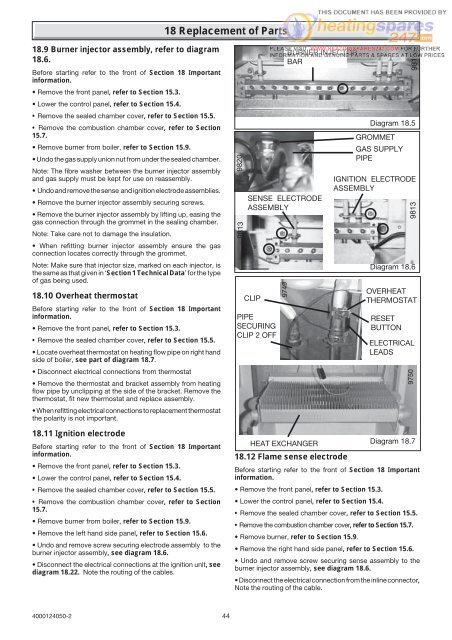
18 Replacement of Parts18.9 Burner injector assembly, refer to diagram18.6.Before starting refer to the front of Section 18 Importantinformation.• Remove the front panel, refer to Section 15.3.• Lower the control panel, refer to Section 15.4.• Remove the sealed chamber cover, refer to Section 15.5.• Remove the combustion chamber cover, refer to Section15.7.• Remove burner from boiler, refer to Section 15.9.• Undo the gas supply union nut from under the sealed chamber.Note: The fibre washer between the burner injector assemblyand gas supply must be kept for use on reassembly.• Undo and remove the sense and ignition electrode assemblies.• Remove the burner injector assembly securing screws.• Remove the burner injector assembly by lifting up, easing thegas connection through the grommet in the sealing chamber.Note: Take care not to damage the insulation.• When refitting burner injector assembly ensure the gasconnection locates correctly through the grommet.Note: Make sure that injector size, marked on each injector, isthe same as that given in ‘Section 1 Technical Data’ for the typeof gas being used.18.10 Overheat thermostatBefore starting refer to the front of Section 18 Importantinformation.• Remove the front panel, refer to Section 15.3.• Remove the sealed chamber cover, refer to Section 15.5.• Locate overheat thermostat on heating flow pipe on right handside of boiler, see part of diagram 18.7.• Disconnect electrical connections from thermostat• Remove the thermostat and bracket assembly from heatingflow pipe by unclipping at the side of the bracket. Remove thethermostat, fit new thermostat and replace assembly.• When refitting electrical connections to replacement thermostatthe polarity is not important.18.11 Ignition electrodeBefore starting refer to the front of Section 18 Importantinformation.• Remove the front panel, refer to Section 15.3.• Lower the control panel, refer to Section 15.4.• Remove the sealed chamber cover, refer to Section 15.5.• Remove the combustion chamber cover, refer to Section15.7.• Remove burner from boiler, refer to Section 15.9.• Remove the left hand side panel, refer to Section 15.6.• Undo and remove screw securing electrode assembly to theburner injector assembly, see diagram 18.6.• Disconnect the electrical connections at the ignition unit, seediagram 18.22. Note the routing of the cables.9813 9820SENSE ELECTRODEASSEMBLYCLIPPIPESECURINGCLIP 2 OFF9749BURNER INJECTORBARHEAT EXCHANGER18.12 Flame sense electrodeGROMMETGAS SUPPLYPIPE9819aDiagram 18.5IGNITION ELECTRODEASSEMBLYDiagram 18.6OVERHEATTHERMOSTATRESETBUTTON9813ELECTRICALLEADS9750Diagram 18.7Before starting refer to the front of Section 18 Importantinformation.• Remove the front panel, refer to Section 15.3.• Lower the control panel, refer to Section 15.4.• Remove the sealed chamber cover, refer to Section 15.5.• Remove the combustion chamber cover, refer to Section 15.7.• Remove burner, refer to Section 15.9.• Remove the right hand side panel, refer to Section 15.6.• Undo and remove screw securing sense assembly to theburner injector assembly, see diagram 18.6.• Disconnect the electrical connection from the inline connector,Note the routing of the cable.4000124050-244