Saunier-Duval-Thema-Classic-F24e-Installation-manual
Saunier-Duval-Thema-Classic-F24e-Installation-manual
Saunier-Duval-Thema-Classic-F24e-Installation-manual
- No tags were found...

You also want an ePaper? Increase the reach of your titles
YUMPU automatically turns print PDFs into web optimized ePapers that Google loves.
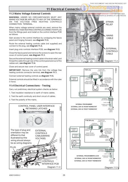
11.3 Mains Voltage External ControlsWARNING: UNDER NO CIRCUMSTANCES MUST ANYMAINS VOLTAGE BE APPLIED TO ANY OF THE TERMINALSON THE VOLTAGE FREE HEATING CONTROLSCONNECTION TERMINAL.When mains voltage external controls are used, remove theMAINS VOLTAGE HEATING CONTROLS CONNECTION PLUGfrom the fittings pack and install on the control interface PCBas follows.Gain access to the control interface by unclipping the fasciapanel and hinging forward, see diagram 11.3.Route the external heating controls cable (not supplied) andconnect to the plug, see diagram 11.3.Insert plug onto controls interface PCB, see diagram 11.3.Close the fascia panel and remove the screws to open the rearcover of control panel, see diagram 11.1.Secure the external heating control cable in the strain relief, andthread the cable through rear of the control panel and out of thecables exit, see diagram 11.4.Close and secure rear cover of control panel.IMPORTANT: Remove the wire link from the voltage freeheating controls connector terminal, see diagram 11.1.Connect external heating controls as diagram 11.5.External controls should be fitted in accordance with the rulesin force.11.4 Electrical Connections - TestingCarry out preliminary electrical system checks as below:1. Test insulation resistance to earth of mains cables.2. Test the earth continuity and short circuit of cables.3. Test the polarity of the mains.11 Electrical ConnectionEXTERNALFROSTTHERMOSTATEXTERNALROOMTHERMOSTATF24E onlyCONTROLSINTERFACE PCB32X1DO NOTCONNECTMAINS VOLTAGEHEATING CONTROLSCONNECTION PLUGPROGRAMMERTO MAIN PCBCONNECTOR J15VOLTAGE FREEHEATING CONTROLSCONNECTION(ON CONTROLSBOX COVER)REMOVE LINKWHEN ANY EXTERNALCONTROLS ARE USEDON/OFFSWITCHEXTERNALJUNCTION BOXSTRAINRELIEFMAINSCABLEEXTERNALCONTROLSCABLEDiagram 11.411992CONTROL PANEL USER INTERFACERETAINING LATCHES➜➜9762INTERNAL PROGRAMMEREXTERNAL 230V AC ROOM THERMOSTATEXTERNAL 230V AC FROST THERMOSTAT3 AMP FUSEDOUBLE POLEISOLATORL N E230V~ 50HzPERMANENTMAINSSUPPLYThe type of plug andorientation may bedifferent to thatillustrated but thewiring should alwaysbe as wiring diagramsEXTERNALCONTROLSCABLE(MAINSVOLTAGE)11974EXTERNALFROSTTHERMOSTATEXTERNALROOMTHERMOSTATEXTERNALPROGRAMMERF18E SB only TO MAIN PCBCONNECTOR J15CONTROLSINTERFACE PCBXDO NOTCONNECTMAINS VOLTAGEHEATING CONTROLSCONNECTION PLUG321VOLTAGE FREEHEATING CONTROLSCONNECTION(ON CONTROLSBOX COVER)REMOVE LINKWHEN ANY EXTERNALCONTROLS ARE USEDON/OFFSWITCH11993PLUGEXTERNALJUNCTION BOXCONTROLSINTERFACE PCBDiagram 11.3EXTERNAL PROGRAMMER/CLOCKEXTERNAL 230V AC ROOM THERMOSTATEXTERNAL 230V AC FROST THERMOSTAT3 AMP FUSEDOUBLE POLEISOLATORL N E230V~ 50HzPERMANENTMAINSSUPPLYDiagram 11.54000124050-226