Saunier-Duval-Thema-Classic-F24e-Installation-manual
Saunier-Duval-Thema-Classic-F24e-Installation-manual
Saunier-Duval-Thema-Classic-F24e-Installation-manual
- No tags were found...

Create successful ePaper yourself
Turn your PDF publications into a flip-book with our unique Google optimized e-Paper software.
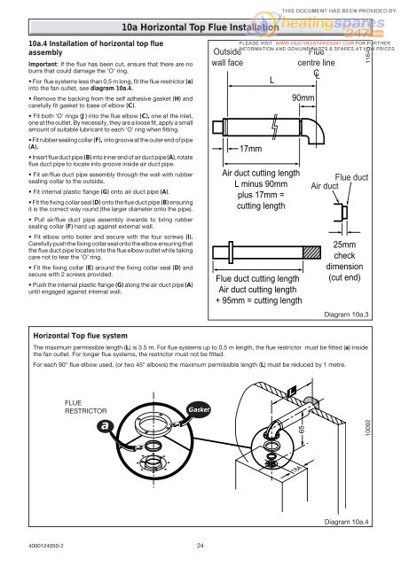
18410a Horizontal Top Flue <strong>Installation</strong>10a.4 <strong>Installation</strong> of horizontal top flueassemblyImportant: If the flue has been cut, ensure that there are noburrs that could damage the ‘O’ ring.• For flue systems less than 0,5 m long, fit the flue restrictor (a)into the fan outlet, see diagram 10a.4.• Remove the backing from the self adhesive gasket (H) andcarefully fit gasket to base of elbow (C).• Fit both ‘O’ rings (J) into the flue elbow (C), one at the inlet,one at the outlet. By necessity, they are a loose fit, apply a smallamount of suitable lubricant to each ‘O’ ring when fitting.• Fit rubber sealing collar (F), into groove at the outer end of pipe(A).• Insert flue duct pipe (B) into inner end of air duct pipe (A), rotateflue duct pipe to locate into groove inside air duct pipe.• Fit air/flue duct pipe assembly through the wall with rubbersealing collar to the outside.• Fit internal plastic flange (G) onto air duct pipe (A).• Fit the fixing collar seal (D) onto the flue duct pipe (B) ensuringit is the correct way round (the larger diameter onto the pipe).• Pull air/flue duct pipe assembly inwards to bring rubbersealing collar (F) hard up against external wall.• Fit elbow onto boiler and secure with the four screws (I).Carefully push the fixing collar seal onto the elbow ensuring thatthe flue duct pipe locates into the flue elbow outlet while takingcare not to tear the ‘O’ ring.• Fit the fixing collar (E) around the fixing collar seal (D) andsecure with 2 screws provided.• Push the internal plastic flange (G) along the air duct pipe (A)until engaged against internal wall.Outsidewall face17mmLAir duct cutting lengthL minus 90mmplus 17mm =cutting length90mmFlue duct cutting lengthAir duct cutting length+ 95mm = cutting lengthFluecentre lineCL25mmcheckdimension(cut end)11643Flue ductAir ductDiagram 10a.3Horizontal Top flue systemThe maximum permissible length (L) is 3.5 m. For flue systems up to 0.5 m length, the flue restrictor must be fitted (a) insidethe fan outlet. For longer flue systems, the restrictor must not be fitted.For each 90° flue elbow used, (or two 45° elbows) the maximum permissible length (L) must be reduced by 1 metre.FLUERESTRICTORaGasketL6510092Diagram 10a.44000124050-224