Saunier-Duval-Thema-Classic-F24e-Installation-manual
Saunier-Duval-Thema-Classic-F24e-Installation-manual
Saunier-Duval-Thema-Classic-F24e-Installation-manual
- No tags were found...

You also want an ePaper? Increase the reach of your titles
YUMPU automatically turns print PDFs into web optimized ePapers that Google loves.
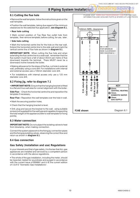
8.1 Cutting the flue hole• Remove the wall template, follow the instructions given on thewall template.• Position the wall template, taking due regard of the minimumclearances for the selected flue application, see diagram 8.1.• Rear hole cutting• Mark correct position of Top Rear flue outlet hole fromtemplate, then remove template, before cutting, for use, later.• Side hole cutting• Mark the horizontal centre line for the hole on the rear wall.Extend the horizontal centre line to the side wall and mark thevertical centre line of flue hole as shown in diagram 8.1.IMPORTANT NOTE: When cutting the flue hole and whenextending the flue centre line to a side wall, remember that theflue system must have a fall of about 35mm per metre of fluedownward towards the terminal. There MUST never be adownward incline towards the boiler.• Making allowance for the slope of the flue, cut hole in externalwall, preferably using a core drill. For installations with internaland external access use a 105mm diameter core drill.• For installations with internal access only use a 125 mmdiameter core drill.8 Piping System <strong>Installation</strong>8.2 Fixing jig, refer to diagram 7.1• IMPORTANT NOTE: Ensure that the hanging bracket is fittedto a flat and true wall area for correct alignment with the boiler.Side Flue - Check the horizontal centre line and reposition thetemplate if necessary.Rear Flue - Reposition the wall template over the hole in wall.• Mark the securing position holes.• Check that the hanging bracket is level.• Drill, plug and secure the bracket to the wall, using suitablescrews (not supplied) for the wall type and capable of supportingthe total weight of the appliance (refer to wall template for fixingpoints).8.3 Water connectionIMPORTANT NOTE: Do not subject the isolating valves to heatfrom blowlamp, when making connection.Connect the system pipework to the fixing jig connection pipesand the fixing jig isolating valves, observing the correct flow andreturn as shown in diagram 8.1.8.4 Gas connectionGas Safety (<strong>Installation</strong> and use) RegulationsIn your interests and that of gas safety, it is the law that ALL gasappliances are installed and serviced by a competent personin accordance with the above regulations.• The whole of the gas installation, including the meter, shouldbe inpected, tested for soundness and purged in accordancewith the current issue of BS6891 and in IE the current editionof I.S.813 "Domestic Gas <strong>Installation</strong>s".F24E shownDiagram 8.119 4000124050-2