You also want an ePaper? Increase the reach of your titles
YUMPU automatically turns print PDFs into web optimized ePapers that Google loves.
<strong>584</strong><strong>Tilt</strong>-<strong>Tower</strong><strong>Tire</strong><strong>Changer</strong>Instruction Manual and Parts ListKwik-Way Products Inc. 800-553-5953Copyright 2006. All Rights ReservedEquipment specifications, options and accessories subject to change without notice.
<strong>584</strong> <strong>Tire</strong> <strong>Changer</strong>521 WARRANTYBrake Lathes · <strong>Tire</strong> <strong>Changer</strong>s ·Wheel BalancersKwik-Way Products Inc. (Kwik-Way) provides a limited 521 Warranty on products when purchased in a newand unused condition to be free from defective material or workmanship from date of purchase as per the following:ProductCategoryBENCH MODELLATHESON-CAR-LATHESPASSENGER CARTIRE CHANGERSWHEELBALANCERSTRUCK LATHESANDTIRE CHANGERS5 YearsSpindle, spindlebearing and housingCast ironcomponents,excluding guide rodsTransmissionFrame, weldingconstructionN/A2 YearsAll other mechanicalpartsAll other mechanicalpartsAll other mechanicalpartsAll other mechanicalpartsN/A1 YearMotor, electricalcomponents andlaborMotor, electricalcomponents andlaborMotor, electricalcomponents andlaborMotor, electricalcomponents andlaborMachine, componentsand laborKwik-Way will repair and/or replace, free of charge (FOB factory) all such defective parts, only whenreturned to factory with shipping charges prepaid. This warranty does not cover parts and supplies (nyloninserts, nylon mount-demount heads, breaker blade covers, and mount-demount covers) consumed innormal operation of the machine.Kwik-Way disclaims all other warranties, expressed or implied, as to the quality of any goods, includingimplied warranties of MERCHANTABILITY and FITNESS FOR PARTICULAR PURPOSES. UNDER NOCIRCUMSTANCES WHATSOEVER, SHALL Kwik-Way BE LIABLE FOR ANY INCIDENTAL ORCONSEQUENTIAL DAMAGES, WHETHER BASED ON LOST GOODWILL, LOST RESALE PROFITS,WORK STOPPAGE, IMPAIRMENT OF OTHER GOODS OR ARISING OUT OF BREACH OF ANYEXPRESS OR IMPLIED WARRANTY, BREACH OF CONTRACT, NEGLIGENCE OR OTHERWISE,EXCEPT ONLY IN THE CASE OF PERSONAL INJURY.Because of Kwik-Way’s constant program of product improvement, specifications are subject to changewithout notice.This warranty does not apply to a product that has been purchased in used condition, that has failed dueto improper installation, repairs, service or that has sustained damage caused by accident, improper useor shipment.Model #: Serial #:Purchase Date:For further information or questions, please contact Kwik-Way Products Inc. at 800/553-5953 or319/377-9421, fax 319/377-9101, email service@kwik-way.comKwik-Way Products Inc. 1. 800-553-5953
<strong>584</strong> <strong>Tire</strong> <strong>Changer</strong>RECEIVING SHIPMENTUpon taking delivery of your machine, carefully inspect the assembly before removingthe crating and packing materials.If evidence of damage exists, contact the shipper and Kwik-Way Products Inc.immediately. Although Kwik-Way Products Inc. is not responsible for damageincurred during transit, you will be provided assistance in preparation and filing of anynecessary claims.CAREFULLY READ THIS MANUAL BEFORE ATTEMPTING TO SETUP OROPERATE THIS MACHINE.IMPORTANT NOTEAlways have your serial number ready when communicating with Kwik-Way ProductsInc. regarding parts or service.Keep this manual in a safe place.Date Received:Serial Number:(Serial Number location: Upper left corner at rear of unit)Kwik-Way Products Inc. 3. 800-553-5953
<strong>584</strong> <strong>Tire</strong> <strong>Changer</strong>SAFETY FIRSTThis manual has been prepared for the owner and those responsible for the maintenance of thismachine. It’s purpose aside from proper maintenance and operations, is to promote safetythrough the use of accepted practice. READ THE SAFETY AND OPERATINGINSTRUCTIONS THOROUGHLY BEFORE OPERATING THE MACHINE.In order to obtain maximum life and efficiency from your machine, follow all the instructions inthe operating manuals carefully.The specifications put forth in this manual were in effect at the time of publication. However,owing to Kwik-Way Products Inc. policy of continuous improvement, changes to thesespecifications may be made at any time without obligation.Kwik-Way Products Inc. 4. 800-553-5953
<strong>584</strong> <strong>Tire</strong> <strong>Changer</strong>SAFETY INSTRUCTIONS1. Read, understand and follow the safety and operating instructions found in this manual. Know thelimitations and hazards associated with operating the machine.2. Eye Safety: Wear an approved safety face shield, goggles or safety glasses to protect eyes whenoperating the machine.3. Grounding the Machine: Machines equipped with three prong grounding plugs are so equipped foryour protection against shock hazards and should be plugged directly into a properly grounded threeprongreceptacle in accordance with national electrical codes and local codes and ordinances. Agrounding adapter may be used. If one is used, the green lead should be securely connected to asuitable electrical ground such as a ground wire system. Do not cut off the grounding prong or usean adapter with the grounding prong removed.4. Work Area: Keep the floor around the machine clean and free of tools, tooling, stock scrap and otherforeign material and oil, grease or coolant to minimize the danger of tripping or slipping. Kwik-Wayrecommends the use of anti-skid floor strips on the floor area where the operator normally stands andthat each machine's work area be marked off. Make certain the work area is well lighted andventilated. Provide for adequate workspace around the machine.5. Guards: Keep all machine guards in place at all times when machine is in use.6. Do Not Overreach: Maintain a balanced stance and keep your body under control at all times.7. Hand Safety: NEVER wear gloves while operating this machine.8. Machine Capacity: Do not attempt to use the machine beyond its stated capacity or operations. Thistype of use will reduce the productive life of the machine and could cause the breakage of parts,which could result in personal injury.9. Avoid Accidental Starting: Make certain the main switch is in the OFF position before connectingpower to the machine.10. Careless Acts: Give the work you are doing your undivided attention. Looking around, carrying on aconversation and horseplay are careless acts that can result in serious injury.11. Job Completion: If the operation is complete, the machine should be emptied and the work areacleaned.12. Disconnect All Power and Air to Machine before performing any service or maintenance.13. Replacement Parts: Use only Kwik-Way replacement parts and accessories; otherwise, warranty willbe null and void.14. Misuse: Do not use the machine for other than its intended use. If used for other purposes,Kwik-Way Products Inc. disclaims any real or implied warranty and holds itself harmless for any injuryor loss that may result from such use.Kwik-Way Products Inc. 5. 800-553-5953
<strong>584</strong> <strong>Tire</strong> <strong>Changer</strong>TECHNICAL DATA-Dimensions Metric EnglishHeight 1890 mm 75”Depth 1092 mm 43”Width 1016 mm 40”WeightNet 220 kg 484 lbs.Gross 247 kg 543 lbs.ElectricalSupply N/A 115V 1ph 60 hzHP 0.75 kw 1 HPBead Breaker Force 2,500 kg 5,500 lbsNoise Level75 dbPneumatic SupplyOperating Pressure 800/1200 kPa 115/173psi(8 /12 bar)RANGE OF APPLICATIONAutomotive WheelsMin.Max.Wheel Width 76 mm - 3” 305 mm - 12”Rim Diameter (internal locking) 305 mm - 12” 572 mm - 22.5”Rim diameter (external locking) 254 mm - 10” 508 mm - 20”Maximum Wheel Diameter 1000 mm - 44”Kwik-Way Products Inc. 6. 800-553-5953
<strong>584</strong> <strong>Tire</strong> <strong>Changer</strong>UNPACKINGREMOVING THE BOX:After removing the bands, remove the cardboard cover and carefully inspect the machine formissing or damaged parts. If in doubt, contact your sales representative or Kwik-Way direct.A box containing your accessories is packed within the box for the machine. Please open andinspect the accessories provided.NOTE: Discard all non-biodegradable packaging at the appropriate collection points. Allpackaging materials are potentially hazardous to children. Dispose of all materials in aresponsible way.LOCATION OF THE MACHINELOCATION:The tire changer must be placed on a solid floor or surface, and should not be any closer to awall or fixed object than 20”. This is to provide for a safe and ergonomic operation of themachine.Kwik-Way Products Inc. 7. 800-553-5953
<strong>584</strong> <strong>Tire</strong> <strong>Changer</strong>INSTALLATIONCheck the voltage at the wall outlet to be used to verify voltage supply matches the voltage onthe electrical tag located at the rear of the machine by the cord set.Attach the air supply to the air regulator at the rear of the machine. Check to verify that there areno air leaks and the regulator is adjusted to 115 psi minimum.TROUBLE SHOOTING GUIDEMalfunction Possible Cause Possible SolutionTurn table does not rotate 1. Power cord not plugged in2. Voltage supply low1. Plug cord into outlet2. Check voltage at outletInsufficient turn table power 1. Supply voltage low2. Drive belt loose1. Check voltage 110v min.2. Retention beltRim clamps do not hold rimsecurelyBead breaker does not havesufficient power to break the tirebead1. Low Air Pressure2. Air regulator not adjustedcorrectly1. Low air pressure2. Air regulator not adjustedcorrectly1. Check supply air pressure(115 /173 psi)2. Adjust regulator to 115psi min.1. Check supply air pressure(115 /173 psi)2. Adjust regulator to 115 psimin.NOTE: Other malfunctions may occur which would be largely technical in nature. Pleasecall a qualified technician or Kwik-Way Products for assistance.Kwik-Way Products Inc. 8. 800-553-5953
<strong>584</strong> <strong>Tire</strong> <strong>Changer</strong>MACHINE DESCRIPTION1) PEDAL CONTROLSREVERSING PEDAL (A) controls the direction of rotation for the table. By pressingdown, the table will rotate in a clockwise rotation as viewed from the top. Lifting up willreverse the direction of rotation to counterclockwise. The switch is spring loaded and willreturn to a center off position when released.BEAD BREAKER PEDAL (B) is used to activate the bead breaker arm. Holding thepedal down activates the arm, you must release the pedal to deactivate. (release)TABLE CLAMP PEDAL (C) operates the rim clamps, pedal down will close the clampswhile pedal up will open the clamps. The pedal has detente position, and with practice,assists in control of the opening or closing the clamps.INFLATER PEDAL (D) has two positions, the first position activates the air inflation hoseand gauge, while the second operates the table blast valve to assist in tire beading.IJGKHLDMCBAFEKwik-Way Products Inc. 9. 800-553-5953
<strong>584</strong> <strong>Tire</strong> <strong>Changer</strong>MACHINE DESCRIPTION(continued)TILT TOWER PEDAL (M) used to tilt tower forward and back2) BEAD BREAKER ASSEMBLYBEAD BREAKER PLATE (E) is used to separate the tire from the rim.BEAD BREAKER PAD (F) support the tire and rim during the bead breaking operation.3) COLUMN / TILT BACK ASSEMBLYSLIDE ARM (G) moves in and out to accommodate various rim diametersMOUNT / DEMOUNT HEAD (H) with the help of the bead lifting lever, is used to removethe tire from and also remount the tire to the rim.TRIGGER (I) when engaged holds the mount / demount head in the correct position forthe dismounting and remounting tires to rims. Press trigger to release when movingmount demount head in/out or up /down.HANDWHEEL (J) is used to position the mount / demount head so as to allow tireremoval without the head actually touching the rim.TOWER TAB (K) is a plastic insert that protects the rim from contact to the mount /demount head.4) TURNTABLE ASSEMBLYRIM CLAMP JAWS (L) hold the rim to the table by clamping for either internal orexternal application.Kwik-Way Products Inc. 10. 800-553-5953
<strong>584</strong> <strong>Tire</strong> <strong>Changer</strong>MACHINE OPERATIONIt is highly recommended that you study and familiarize yourself with the nomenclatureof the machine before attempting operation.BEAD BREAKING OPERATIONIn preparation of the bead breaking operation remove the valve stem core and completelydeflate the tire. Remove any wheel weights that are present.NOTE: If the tire is being removed for repair, and the assembly is not to be rebalanced, markthe location of the wheel weight or weights on the rim and mark the tire at the valve stemlocation. This will provide a reference for tire relocation and correct wheel weight placementafter remount.BE1. Place the wheel assembly against the breaker pads and carefully position the breaker bladeso as to have the radius of the blade slightly inside of the radius of the rim.NOTE: It is highly recommended when breaking beads on alloy or chrome wheels to use theoptional breaker blade protector to prevent scratching and or other possible damage.2. Step down on the bead breaker pedal (B), the blade (E) will push the tire bead from the rimflange.3. Repeat this operation at various points around the rim diameter and on both sides of thewheel.Kwik-Way Products Inc. 11. 800-553-5953
<strong>584</strong> <strong>Tire</strong> <strong>Changer</strong>DISMOUNTING THE TIREMove the swing arm to the rear position so as to permit mounting the wheel assembly to theturntable.NOTE: It is highly recommended to externally clamp all rims whenever possible, especiallyalloy and chrome rims, so as to prevent possible damage during dismount.1. Press down on the clamp jaw pedal to expand the jaws.2. Position the wheel on the table clamps and while pressing down slightly on the wheel, pressthe control pedal to close the jaws. This will lock the wheel assembly to the turntable.3. Move the swing arm to the front so the mount / demount head is over the approximate rimradius. Unlock the tower lock lever and lower the head to the correct position. The radius ofthe head should be against the rim radius.3. Using the swing arm handwheel, adjust the mount / demount head so as to have a 1/16” to1/8” clearance between the head and the rim. This will permit the use of the bead lifting leverwithout contacting the rim. Check the tower tab to be sure it is in place and good condition.NOTE: A good quality rubber lube should be used while removing the tire from the rim, it willspeed up the operation as well as prevent damage to the bead.4. Insert the bead lever, positioning the lever in the notch of the head. Lift the upper tire beadover the demount ramp of the head. Step down on the table rotation pedal. The turntable willrotate clockwise removing the upper tire bead.5. Repeat the above operation on the lower bead. Remember to lube the lower bead beforeattempting removal.6. Move the swing arm to the rear to permit removal of the tire.Kwik-Way Products Inc. 12. 800-553-5953
<strong>584</strong> <strong>Tire</strong> <strong>Changer</strong>MOUNTING THE TIREIn preparation for mounting a tire to the rim, check the tire and rim diameter to assure correctsize. Lubricate both beads thoroughly with the tire lube.CAUTION: Never attempt to mount a tire without verifying size. The most common mistakeis attempting to mount a 16.0” tire to a 16.5” rim. Personal Injury can result from improperuse.1. Place the tire on the rim, and move the swing arm into position.2. Position the mount / demount head at the radius of the rim, and rotate the swing arm handwheel to provide 1/16” to 1/8” clearance.3. Place the lower bead of the tire over the leading edge of the mount demount head, and whilepressing down on the tire with your hand, step down on the table pedal, the table will rotateclockwise, continue to push the bead of the tire into the drop center while rotating the table.4. Repeat the above process for the upper bead.NOTE: If it becomes necessary to back the turn table, simply lift up on the table pedaland the table will rotate counterclockwise.Kwik-Way Products Inc. 13. 800-553-5953
<strong>584</strong> <strong>Tire</strong> <strong>Changer</strong>TIRE INFLATION<strong>Tire</strong> inflation can be potentially dangerous! Use only the inflation hose and chuck provided onthe machine to inflate tires.CAUTION: Never exceed 45 psi to bead a tire. If both tire beads fail to bead at 45 psi, breakthe tire bead and rotate the tire on the rim then lubricate with tire lube and attempt to rebeadthe tire.There are blast jets built into the table clamps to assist in tire beading. To operate the blast jets,simply step down on the inflation pedal to the second position and a blast of high pressure airwill be omitted.Kwik-Way Products Inc. 14. 800-553-5953
<strong>584</strong> <strong>Tire</strong> <strong>Changer</strong>ROUTINE MAINTENANCETo insure proper operation of the machine, it is essential to perform periodic maintenance.Mechanical Parts: Keep the moving parts of the machine clean, wash them with naphtha or asimilar product, the lubricate them with oil or greaseLubricator: Check and maintain the oil level in the air lubricator, level must always be within themin/max listed on the outside.Water Separator: Periodically check and remove any water from the separatorTurntable Drive Belt: Check the belt to see that correct tension is maintained and adjust asrequired.Inflation Gauge: Periodically check the gauge for function and accuracyTECHNICAL ASSISTANCE AND SPARE PARTSFor any malfunctions consult the Troubleshooting Guide on Page 8 of this manual. Anymalfunctions other than those listed should be checked by a qualified technician. For promptassistance, please have you machine model and serial number on ready when you place yourcall.Any SPARE PARTS must be ordered from Kwik-Way or an authorized distributor, themanufacturer denies all responsibility for damage or malfunctions resulting from use of nonoriginalsubstituted parts.Kwik-Way Products Inc. 15. 800-553-5953
<strong>584</strong> <strong>Tire</strong> <strong>Changer</strong>TOOL ARMKwik-Way Products Inc 16. 800-553-5953
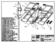
<strong>584</strong> <strong>Tire</strong> <strong>Changer</strong>TOOL ARM(continued)REF PART # DESCRIPTION1 <strong>584</strong>-8111-50 <strong>Tilt</strong>ing Post2 <strong>584</strong>-0015-10 Spring3 <strong>584</strong>-9107-00 Roller4 <strong>584</strong>-3016-40 Lock Plate5 <strong>584</strong>-8906-30 Horizontal Lock Plate Cylinder6 <strong>584</strong>-9106-20 Operation Tool Label7 <strong>584</strong>-3012-32 Cover8 <strong>584</strong>-3017-00 Cover9 <strong>584</strong>-3905-11 Upper Cover Group10 <strong>584</strong>-8102-10 Sliding Roll11 <strong>584</strong>-2340-89 Cylindrical Pin12 580-7101-60 Handgrip13 580-3203-10 Washer14 580-0202-10 Spring15 <strong>584</strong>-7100-90 Lock Plate16 580-3170-04 8 x 6 x 1.5 mm Airline17 <strong>584</strong>-3090-09 Valve18 582-4153-90 Shaft19 582-3157-20 Bumper20 580-3153-91 Spacer21 580-3014-80 Pin22 <strong>584</strong>-9132-80 Danger Label <strong>Tilt</strong>ing Pad23 <strong>584</strong>-8906-40 Vertical Lock Plate Cylinder24 <strong>584</strong>-7101-70 Buffer25 <strong>584</strong>-3102-30 Spacer26 <strong>584</strong>-8111-20 Tube Guide27 <strong>584</strong>-9112-10 Horizontal Arm28 <strong>584</strong>-8302-47 Buffer29 <strong>584</strong>-9107-11 Cone30 <strong>584</strong>-9911-00 Tool Arm Group31 580-3802-02 <strong>Tower</strong> Tab32 582-3926-00 Projecting Spokes Tool Kit33 582-3057-00 Projecting Spokes Tool Body34 582-3020-00 Roller for Bike Tool35 582-8301-49 Bike Tool Roller Pin36 580-3170-10 Tube 10 x 8 x 3.0 mmKwik-Way Products Inc. 17. 800-553-5953
<strong>584</strong> <strong>Tire</strong> <strong>Changer</strong>TILTING PAD PISTONKwik-Way Products Inc 18. 800-553-5953
<strong>584</strong> <strong>Tire</strong> <strong>Changer</strong>TILTING PAD PISTON(continued)REF PART # DESCRIPTION1 <strong>584</strong>-8911-00 <strong>Tilt</strong>ing Pad Piston Group2 <strong>584</strong>-3907-70 Complete Piston3 580-3251-11 Quick Disconnect 1/8 x 6 mm4 <strong>584</strong>-4131-85 Shock Absorber5 580-2430-06 Snap-Ring 14 mm6 <strong>584</strong>-0301-31 Pin7 <strong>584</strong>-3905-31 <strong>Tilt</strong>ing Pad Assembly – Frame8 <strong>584</strong>-9111-60 Plate 1.5mm9 <strong>584</strong>-9111-70 Plate 3.5mm10 <strong>584</strong>-9111-50 Plate 2.5mm11 <strong>584</strong>-8103-91 Arm Closure Guard12 Not Shown Not Shown13 <strong>584</strong>-2030-62 Screw14 <strong>584</strong>-2190-10 Guide Screw15 <strong>584</strong>-2031-86 Screw16 <strong>584</strong>-2240-11 Nut17 <strong>584</strong>-3152-11 Pad Pin18 <strong>584</strong>-2375-01 Washer19 <strong>584</strong>-2375-11 Washer20 580-3153-91 SpacerA 580-3080-00 Gaskets KitKwik-Way Products Inc 19. 800-553-5953
<strong>584</strong> <strong>Tire</strong> <strong>Changer</strong>FRAMEREF PART # DESCRIPTION1 580-4050-18 Frame2 580-0315-22 Bead Breaker Pad3 580-5993-85 Gromet4 580-5990-74 Gromet w/Nut5 580-4904-80 Frame Assembly6 580-3302-42 Side CoverKwik-Way Products Inc 20. 800-553-5953
<strong>584</strong> <strong>Tire</strong> <strong>Changer</strong>ROTATING FITTINGREF PART # DESCRIPTION1 580-3020-92 Complete Distributor2 580-3251-11 Quick Disconnect 1/8” x 6 mm3 580-3030-21 Direct Coupling 3/8” x 14 mm4 580-3251-10 Direct Coupling 1/8” x 6 mm5 580-3305-00 Fixed Body6 580-3305-10 Movable BodyA 580-4300-00 Seal KitKwik-Way Products Inc 21. 800-553-5953
<strong>584</strong> <strong>Tire</strong> <strong>Changer</strong>TURNTABLEKwik-Way Products Inc 22. 800-553-5953
<strong>584</strong> <strong>Tire</strong> <strong>Changer</strong>TURNTABLE(continued)REF PART # DESCRIPTION1 582-8109-30 Tie Rod2 580-3251-11 Quick Disconnect 1/8 x 6 mm3 580-3251-08 L-Shaped Fitting 1/8 x 6 mm4 582-8909-90 Complete Piston5 580-3170-20 Airline 6 x 4 x 1.46 mm6 580-8153-72 U-Bolt7 580-2430-06 Snap-Ring 148 580-8156-00 Slide Guide Bushing9 580-2430-54 Seeger10 582-8156-50 Connecting Rod Control Flange11 582-8156-40 Small Tube12 580-8153-21 Slide Guide13 582-8157-00 Turntable14 582-8156-80 Slide15 580-8150-42 Jaw16 580-8380-07 Nylon Insert17 582-8151-32 Finger Protection18 580-2350-52 Elastic Pin19 580-4402-40 Turntable Cover20 582-8909-80 Turntable Unit 12” – 24”21 582-8156-20 Block22 582-8156-10 U Bolt Block23 580-3251-21 L-Shaped Fitting ¼ x 8 mm24 580-3170-22 Air line 8 x 6 x 3.025 580-8151-41 BushingA 580-3080-00 Gasket KitKwik-Way Products Inc 23. 800-553-5953
<strong>584</strong> <strong>Tire</strong> <strong>Changer</strong>GEARED MOTORKwik-Way Products Inc 24. 800-553-5953
<strong>584</strong> <strong>Tire</strong> <strong>Changer</strong>GEARED MOTOR(continued)REF PART # DESCRIPTION1 580-0305-24 Pulley2 580-4120-20 Belt3 580-4153-40 Pulley 60 Hz.4 580-2310-03 Key5 N/A Cable6 580-0002-91 Motor 1 Ph – 0.75 kW 110V – 60 Hz7 580-0305-26 Motor Plate8 580-2310-68 Key9 580-0305-28 Tie Rod10 580-0305-32 Tie Rod11 580-3050-21 Complete Gear Box/Transmission12 580-4130-89 Plug13 580-2310-67 Key14 580-3055-90 Extension15 580-3056-00 Oil Level Staff16 580-3906-90 Reduction Unit - CompleteKwik-Way Products Inc 25. 800-553-5953
<strong>584</strong> <strong>Tire</strong> <strong>Changer</strong>CONTROL PEDAL UNITKwik-Way Products Inc 26. 800-553-5953
<strong>584</strong> <strong>Tire</strong> <strong>Changer</strong>CONTROL PEDAL UNIT(continued)REF PART # DESCRIPTION1 580-9150-11 Pedal Panel Body2 580-9129-50 Pedal Unit Operation Label3 580-3104-10 Bushing4 580-9150-30 Pedal5 580-2990-52 Ring6 580-9151-70 Pin7 580-2300-31 Split Pin8 580-9151-60 Lever9 580-0200-40 Spring10 580-9906-00 Turning Table Pedal Group11 580-9150-50 Tie Rod12 580-3104-20 Inverter Attachment13 580-3104-50 Support14 580-9906-20 Inverter Group15 580-5182-12 Inverter/Foot Pedal Switch16 580-9650-71 Inverter/Motor Cable17 580-3650-40 Feed Cable (Single Phase)18 580-9980-11 Bead Breaker Valve S.E. Assembly19 580-3990-64 Silencer20 580-3110-02 Plug21 580-3251-13 Swivel T ¼” x 8 mm22 580-3251-09 Union ¼” x 10 mm23 580-9905-00 Bead Breaker Pedal Group24 580-9980-70 Chucking Table Distributor Assembly25 580-9904-00 Chucking Table Opening/Closure Pedal Group26 580-3251-12 Quick Disconnect ¼” x 6 mm27 580-3251-21 Quick Disconnect ¼” x 8 mm28 580-9151-00 Cam29 580-9151-10 Cover30 580-9151-80 Pin31 580-3104-81 Protection32 580-9905-90 Control Pedal UnitKwik-Way Products Inc 27. 800-553-5953
<strong>584</strong> <strong>Tire</strong> <strong>Changer</strong>TUBELESS INFLATINGKwik-Way Products Inc 28. 800-553-5953
<strong>584</strong> <strong>Tire</strong> <strong>Changer</strong>TUBELESS INFLATING(continued)REF PART # DESCRIPTION1 580-3902-50 Tubeless Inflating Group2 580-3307-10 Tank Assembly with Valve and Fittings3 580-3170-14 Tube 4 x 2 x 3.00 mm4 580-3180-10 PVC Screened Tube Ø 13 x 195 580-3190-12 Clamp6 580-3170-07 Airline 8 x 6 mm x 3.07 580-3982-82 Tubeless Inflating Valve8 580-9110-80 Support9 580-0132-00 Spring10 580-3251-18 Fitting11 580-3251-17 Fitting12 580-0200-40 Spring13 580-9152-40 Pedal Assembly14 580-9130-60 GT Pedal Label15 580-9150-30 Pedal16 580-9152-50 Pin17 580-2990-52 Ring18 580-9903-70 Tubeless Inflating Pedal19 580-7251-70 Body20 580-4010-49 “O” Ring21 580-7251-81 Tank Plug22 580-3251-08 L-Shaped Fitting 1 x 8 x 6 mm23 580-3050-16 Fitting24 580-7151-80 Inflating Valve25 580-9090-38 Pressure Gauge26 580-7251-61 Support Steel27 580-3251-47 Fitting28 580-3992-41 Inflation Hose w/Cup29 580-3251-21 L-Shaped Fitting1/4 x 8 mm30 580-3090-95 Blast Valve31 580-9118-70 Earcaps Use Label32 580-3170-06 Airline 6 x 4 x 3 mm33 580-7902-40 Inflating UnitKwik-Way Products Inc 29. 800-553-5953
<strong>584</strong> <strong>Tire</strong> <strong>Changer</strong>PNEUMATIC CIRCUITREF PART # DESCRIPTION1 580-3170-06 Airline 6 x 4 mm x 3.02 580-3170-07 Airline 8 x 6 mm x 3.03 580-3170-10 Airline 10 x 8 mm x 3.04 580-3170-04 Airline 8 x 6 x 1.5 mm5 580-3180-10 PVC Screened Airline 13 x 19 mm6 580-3060-13 T-Fitting7 580-3251-21 Disconnect ¼” x 8 mm; L-Shaped Fitting ¼ x 8 mm8 580-3030-15 Corrugated Fitting9 580-3251-18 Fitting10 580-3904-00 Air Treatment Assembly11 580-1204-20 Bracket12 580-3992-05 LubricatorKwik-Way Products Inc 30. 800-553-5953
<strong>584</strong> <strong>Tire</strong> <strong>Changer</strong>EQUIPMENTREF PART # DESCRIPTION1 580-9020-78 Hand Grip2 580-2991-11 <strong>Tire</strong> Iron3 580-9990-11 Lube BrushKwik-Way Products Inc 31. 800-553-5953
<strong>584</strong> <strong>Tire</strong> <strong>Changer</strong>BEAD BREAKERKwik-Way Products Inc 32. 800-553-5953
<strong>584</strong> <strong>Tire</strong> <strong>Changer</strong>BEAD BREAKER(continued)REF PART # DESCRIPTION1 580-0320-07 Pin2 580-0305-07 Brush3 580-0101-44 Spring4 580-3200-12 Bead Breaker Arm5 580-2375-26 Washer6 580-3203-30 Pin7 580-0320-22 Washer8 580-0320-05 Bead Breaker Attachment9 580-0320-19 Spring10 580-0320-18 Shock Absorber11 580-2280-20 Self-Locking Nut 18 mm x 1.5 mm12 580-3925-12 Bead Breaker Arm Assembly13 580-3200-81 Bead Breaker Blade14 580-9259-00 Pivot Bolt15 580-2280-06 Self-Locking Nut 12mm x 1.75 mm16 580-3902-12 Complete Bead Breaker Assembly17 580-3201-71 Rod18 580-2370-64 Cut Washer19 580-3251-07 Fitting20 580-2280-11 Self-Locking Nut 8 mm x 1.25 mm21 580-3202-12 Cylinder22 580-3202-80 Spacer23 580-2363-00 Washer24 580-2280-15 Self-Locking Nut 18 mm x 1.5 mm25 580-8005-38 Rear Flange26 580-2031-72 Screw 8 mm x 16 mm27 580-9904-90 SE Bead Breaker Group28 580-2430-08 External Snap Ring 16 mmA 580-3710-00 Seal KitKwik-Way Products Inc 33. 800-553-5953
PNEUMATIC SYSTEM OF THE MACHINE<strong>584</strong> <strong>Tire</strong> <strong>Changer</strong>Kwik-Way Products Inc 34. 800-553-5953
<strong>584</strong> <strong>Tire</strong> <strong>Changer</strong>WIRING DIAGRAMKwik-Way Products Inc 35. 800-553-5953
PRO-R KWIK-ASSIST WITH FOLLOWER<strong>584</strong> <strong>Tire</strong> <strong>Changer</strong>The Pro-R Kwik-Assist is essential for dismounting and mounting high performance low profileand EMT (run flat) type tires. Please follow the instructions carefully and observe all cautionsand safety warnings.INSTRUCTIONS FOR USEDISMOUNTING THE TIRENOTE: It is highly recommended to externally clamp all alloy and chrome wheels to preventdamage.1. The insertion of the jaw between the bead of the tire and wheel flange can be difficult. Inorder to push the wheel down to create the distance required, expand the table jaws to thefully open position. With the jaws pinned in the proper position for the wheel diameter, placethe wheel and tire on the table. Now using the large bead roller wheel, position the device asshown in Figure 10. Press down on the air toggle lever in the control panel until the roller isdown onto the wheel and then simultaneously close the table jaws.Figure 10Kwik-Way Products Inc 36. 800-553-5953
PRO-R KWIK-ASSIST WITH FOLLOWER(continued)<strong>584</strong> <strong>Tire</strong> <strong>Changer</strong>2. Sometimes during the demounting, the lower bead may reseat itself. By using the beadroller wheel as shown in Figure 11, it will not be necessary to remove the wheel in order torepeat the bead breaking operation. To raise the lower bead, manually position the arm sothat the bead roller wheel is at the edge of the wheel. While rotating the turntable, raise thebead roller wheel by pushing up on the air toggle lever on the control panel.Figure 11Kwik-Way Products Inc 37. 800-553-5953
PRO-R KWIK-ASSIST WITH FOLLOWER(continued)<strong>584</strong> <strong>Tire</strong> <strong>Changer</strong>3. Remove the upper bead from the wheel flange by insert the bead-lifting tool as described inthe standard tire and wheel dismounting section of the manual. On some low profile tires itmay be necessary to use the supplementary roller to assist in this operation. See Figure 12Figure 124. Once the upper bead is removed, to remove the tire from the wheel, you can use thesupplementary roller as show in Figure 13. Position the roller so that the end of the rollerwheel is in contact with the edge of the wheel flange, this establishes the correct diameterposition. While holding the tire up, raise the roller and rotate the turntable. The bead will bepushed up over the top wheel flange, thus removing the tire. Have the tilt tower in the rearposition to allow for maximum working area.Figure 13Kwik-Way Products Inc 38. 800-553-5953
PRO-R KWIK-ASSIST WITH FOLLOWERPART NUMBER REFERENCES<strong>584</strong> <strong>Tire</strong> <strong>Changer</strong>Kwik-Way Products Inc 39. 800-553-5953
<strong>584</strong> <strong>Tire</strong> <strong>Changer</strong>FOLLOWER ARMMOUNTING THE TIRENOTE: The Pro-R Kwik-Assist is fitted with a helper or follower arm, which is designed to helphold the bead into the drop center of the wheel to assist in beading low profile and EMT tires.1. Install the lower bead onto the wheel following the instructions provided earlier in theremounting section of the manual.2. Position the supplementary roller on to the tire, with the end of the roller at the wheelflange radius.3. Position the helper arm on the upper bead just to the right of the supplementaryroller. Using the air lever on the Pro-R Kwik-Assist panel push the lever down andposition the bead “just’ into the wheel drop center.4. Step down on the table rotation pedal and carefully rotate the tires, while guiding theupper bead over the mount, demount head. Rotate until the upper bead is installedCAUTION:THE FOLLOWER ARM WILL ROTATE WITH THE TIRE, MAKE SURE YOUR HANDS ARECLEAR OF THE MOVING PARTS.NOTE: Always use a quality tire lube to assist in the installation of the tire beads.Kwik-Way Products Inc 40. 800-553-5953
<strong>584</strong> <strong>Tire</strong> <strong>Changer</strong>FOLLOWER ARMPART NUMBER REFERENCESKwik-Way Products Inc 41. 800-553-5953
Kwik-Way Products Inc.500 57 th St., Marion, IA 52302 USA319/377-9421319/377-9101 (FAX)800/553-5953www.kwik-way.comservice@kwik-way.com