Product Manual for Dionex IonPac AS23 Columns - Cromlab
Product Manual for Dionex IonPac AS23 Columns - Cromlab
Product Manual for Dionex IonPac AS23 Columns - Cromlab

Create successful ePaper yourself
Turn your PDF publications into a flip-book with our unique Google optimized e-Paper software.
<strong>Product</strong> <strong>Manual</strong> <strong>for</strong> <strong>IonPac</strong> <strong>AS23</strong> amd <strong>IonPac</strong> AG23 <strong>Columns</strong> Page 1 of 32PRODUCT MANUAL<strong>for</strong> theIONPAC AG23 GUARD COLUMNS(4 x 50 mm, P/N 064147)(2 x 50 mm, P/N 064143)IONPAC <strong>AS23</strong> ANALYTICAL COLUMNS(4 x 250 mm, P/N 064149)(2 x 250 mm, P/N 064145)©2012 Thermo Fisher ScientificDocument No. 065120Revision 05July 2012Document No. 065120-05 ©2012 Thermo Fisher Scientific July 2012
<strong>Product</strong> <strong>Manual</strong> <strong>for</strong> <strong>IonPac</strong> <strong>AS23</strong> amd <strong>IonPac</strong> AG23 <strong>Columns</strong> Page 3 of 32SECTION 5 - EXAMPLE APPLICATIONS .................................................................................... 125.1 Preparation of Eluent Stock Solution Concentrates .............................................................................................. 125.2 Eluent Preparation .................................................................................................................................................. 135.3 <strong>Product</strong>ion Test Chromatograms ........................................................................................................................... 145.4 Effect of Temperature on the <strong>AS23</strong> Selectivity ....................................................................................................... 155.5 Analysis of Simulated Drinking Water ................................................................................................................. 165.6 Separation of Anions in Municipal Drinking Water Spiked with Bromate and Surrogate Anion ...................... 175.7 Analysis of Waste Water with the <strong>IonPac</strong> <strong>AS23</strong> Column ...................................................................................... 185.8 Gradient Separation of Environmental Anions with the <strong>IonPac</strong> <strong>AS23</strong> Column .................................................... 19SECTION 6 - TROUBLESHOOTING GUIDE ............................................................................... 206.1 High Back Pressure ............................................................................................................................................... 216.1.1 Finding the Source of High System Pressure ............................................................................................................ 216.1.2 Replacing Column Bed Support Assemblies ............................................................................................................. 226.2 High Background or Noise ..................................................................................................................................... 236.2.1 Preparation of Eluents ............................................................................................................................................... 236.2.2 A Contaminated Guard or Analytical Column ........................................................................................................... 236.2.3 A Contaminated Anion Trap Column, ATC-3 ............................................................................................................ 236.2.4 Contaminated Hardware ............................................................................................................................................ 236.2.5 A Contaminated Anion Self-Regenerating Suppressor, ASRS ULTRA II ..................................................................236.2.6 A Contaminated Anion MicroMembrane Suppressor, AMMS III ............................................................................. 246.2.7 A Contaminated Anion Atlas Electrolytic Suppressor, AAES ................................................................................... 256.3 Poor Peak Resolution ............................................................................................................................................. 266.3.1 Loss of Column Efficiency ........................................................................................................................................ 266.3.2 Poor Resolution Due to Shortened Retention Times ................................................................................................ 266.3.3 Loss of Front End Resolution ................................................................................................................................... 276.3.4 Spurious Peaks .......................................................................................................................................................... 276.3.5 Poor Resolution of Only Phosphate and Sulfate ....................................................................................................... 28APPENDIX A - COLUMN CARE .................................................................................................... 29A.2 Column Start-Up ...................................................................................................................................................... 29A.3 Column Storage ....................................................................................................................................................... 29A.4 Column Cleanup ...................................................................................................................................................... 29A.4.1 Choosing the Appropriate Cleanup Solution ............................................................................................................ 30A.4.2 Column Cleanup Procedure ....................................................................................................................................... 30APPENDIX B - CONFIGURATION ............................................................................................... 31Document No. 065120-05 ©2012 Thermo Fisher Scientific July 2012
<strong>Product</strong> <strong>Manual</strong> <strong>for</strong> <strong>IonPac</strong> <strong>AS23</strong> amd <strong>IonPac</strong> AG23 <strong>Columns</strong> Page 5 of 32SECTION 2 - ION CHROMATOGRAPHY SYSTEMSThe proper configuration of an Ion Chromatography System (ICS) in 2-mm or 4-mm <strong>for</strong>mat is based on the ratio of the 2-mm to 4-mm column cross-sectional area (a factor of 1/4). The selected <strong>for</strong>mat will affect the type of pump recommended.A gradient pump is designed to blend and pump isocratic, linear, or gradient mixtures of up to four mobile phasecomponents at precisely controlled flow rates. An isocratic pump is <strong>for</strong> applications not requiring gradient and multieluentproportioning capabilities. Both are offered in either standard bore or microbore options.• For an ICS in 2-mm <strong>for</strong>mat, <strong>Dionex</strong> recommends a microbore isocratic pump, standard bore isocratic pump, microboregradient pump, or standard bore gradient pump .• For an ICS in 4-mm <strong>for</strong>mat, <strong>Dionex</strong> recommends a standard bore isocratic pump or standard bore gradient pump.See Appendix B, Comparison of Ion Chromatography Systems <strong>for</strong> specific recommended settings and parts includingpumps, eluent flow rate, suppressor, injection loop, system void volume, detectors, and tubing back pressure.Document No. 065120-05 ©2012 Thermo Fisher Scientific July 2012
<strong>Product</strong> <strong>Manual</strong> <strong>for</strong> <strong>IonPac</strong> <strong>AS23</strong> amd <strong>IonPac</strong> AG23 <strong>Columns</strong> Page 6 of 32SECTION 3 - INSTALLATION3.1 System Requirements3.1.1 System Requirements <strong>for</strong> 2-mm OperationThe <strong>IonPac</strong> <strong>AS23</strong> 2-mm Guard and Analytical <strong>Columns</strong> are designed to run on <strong>Dionex</strong> Ion Chromatographs equippedwith suppressed conductivity detection. Isocratic analyses at flow rates of 0.5 mL/min or greater can be per<strong>for</strong>med ona pump with standard (1/8" pistons) pump heads. For isocratic analyses at flow rates below 0.5 mL/min and gradientanalyses, a microbore pump (1/16" pistons) is recommended.3.1.2 System Requirements <strong>for</strong> 4-mm OperationThe <strong>IonPac</strong> <strong>AS23</strong> 4-mm Guard and Analytical <strong>Columns</strong> are designed to run on any <strong>Dionex</strong> Ion Chromatographequipped with suppressed conductivity detection. Gradient methods and methods requiring solvent containingeluents should be per<strong>for</strong>med on a system having a pump with a standard pump heads (1/8" pistons). Isocraticanalysis can also be per<strong>for</strong>med on a pump with standard bore pump heads (1/8" pistons).3.1.3 System Void VolumeWhen using 2-mm columns, it is particularly important to minimize system void volume. The system void volumeshould be scaled down to at least 1/4 of the system volume in a standard 4 mm system. For best per<strong>for</strong>mance, all ofthe tubing installed between the injection valve and detector should be 0.005"ID PEEK tubing (P/N 044221).0.010" ID PEEK tubing (P/N 042260) may be used but peak efficiency will be compromised which may also result indecreased peak resolution. Minimize the lengths of all connecting tubing and remove all unnecessary switchingvalves and couplers.3.2 The Sample ConcentratorFor 2-mm or 4-mm concentrator work, use the <strong>IonPac</strong> AG23 Guard Column when a single piston pump is used <strong>for</strong> sample delivery.Use the Trace Anion Concentrator Low Pressure Column (TAC-LP1, P/N 046026) or Trace Anion Concentrator Ultra Low PressureColumn (TAC-ULP1, P/N 061400) when the sample is delivered with a syringe or with an autosampler. Alternatively, use the UltraTrace Anion Concentrator Low Pressure Column (UTAC-LP1, P/N 063079), Ultra Trace Anion Concentrator Ultra Low PressureColumn (UTAC-ULP1, P/N 063475), or Ultra Trace Anion Concentrator Extremely Low Pressure Column (UTAC-XLP1, P/N 063459).The TAC-LP1, TAC-ULP1, UTAC-LP1, UTAC-ULP1, UTAC-XLP1, or the <strong>IonPac</strong> AG23 Guard Column can be used <strong>for</strong> trace anionconcentration work. The concentrator column is used in lieu of the sample loop. Pump the sample onto the concentrator columnin the OPPOSITE direction of the eluent flow.When using concentration techniques, do not overload the concentrator column by concentrating an excessive amount of sampleas this can result in inaccurate results being obtained. It is possible during the concentration step <strong>for</strong> the polyvalent anions suchas phosphate and sulfate to elute the weakly retained anions such as fluoride and acetate off the concentrator column.The function of the TAC-LP1, TAC-ULP1, UTAC-LP1, UTAC-ULP1, UTAC-XLP1, or the AG23 Guard Column in these applicationsis to strip ions from a measured volume of a relatively clean aqueous sample matrix. This process “concentrates” all anionic analytespecies onto the TAC-LP1, TAC-ULP1, UTAC-LP1, UTAC-ULP1, UTAC-XLP1, or the AG23 leading to a lowering of detectionlimits by 2–5 orders of magnitude. The unique advantage to the analytical chemist of the TAC-LP1, TAC-ULP1, UTAC-LP1, UTAC-ULP1, UTAC-XLP1, or the AG23 in these applications is the capability of per<strong>for</strong>ming routine trace analyses of sample matrix ionsat μg/L levels without extensive and laborious sample pretreatment.For a detailed discussion of anion concentration techniques, refer to Section 3, “Operation,” of the Trace Anion Concentrator (TAC-LP1 and TAC-ULP1) Column <strong>Product</strong> <strong>Manual</strong> (Document No. 034972) or Section 3, “Operation,” of the Ultra Trace AnionConcentrator (UTAC-XP1, UTAC-ULP1, and UTAC-XLP1) Column <strong>Product</strong> <strong>Manual</strong> (Document No. 065091).Document No. 065120-05 ©2012 Thermo Fisher Scientific July 2012
<strong>Product</strong> <strong>Manual</strong> <strong>for</strong> <strong>IonPac</strong> <strong>AS23</strong> amd <strong>IonPac</strong> AG23 <strong>Columns</strong> Page 7 of 323.3 The Injection Loop3.3.1 The 2-mm System Injection Loop, 2 - 15 μLFor most applications on a 2-mm analytical system, a 2 - 15 μL injection loop is sufficient. Generally, you should not injectmore than 12.5 nanomoles of any one analyte onto a 2-mm analytical column. Injecting larger number of moles of a samplecan result in overloading the column which can affect the detection linearity. For low concentrations of analytes, largerinjection loops can be used to increase sensitivity. The <strong>AS23</strong> 2-mm requires a microbore HPLC system configuration. Installan injection loop one-fourth or less (
<strong>Product</strong> <strong>Manual</strong> <strong>for</strong> <strong>IonPac</strong> <strong>AS23</strong> amd <strong>IonPac</strong> AG23 <strong>Columns</strong> Page 8 of 323.7 Anion Atlas Electrolytic Suppressor (AAES) RequirementsAn Atlas Anion Electrolytic Suppressor (AAES) may be used instead of an ASRS ULTRA II <strong>for</strong> applications that require suppressedconductivity detection. The AAES (P/N 056116) can be used <strong>for</strong> <strong>AS23</strong> 2-mm and 4-mm applications using eluents up to 25 μeq/min.For detailed in<strong>for</strong>mation on the operation of the Atlas Anion Electrolytic Suppressor, see Document No. 031770, the “<strong>Product</strong><strong>Manual</strong> <strong>for</strong> the Anion Atlas Electrolytic Suppressor.”3.8 Anion MicroMembrane Suppressor (AMMS III) RequirementsAn Anion MicroMembrane Suppressor (AMMS III) may be used instead of an ASRS ULTRA II (4-mm) <strong>for</strong> applications that requiresuppressed conductivity detection. Use an AMMS III (P/N 056750) with the <strong>IonPac</strong> <strong>AS23</strong> 4-mm Analytical Column. It is compatiblewith all solvents and concentrations with which the systems and columns are compatible. For 2-mm operation, use the AMMS III(P/N 056751).For detailed in<strong>for</strong>mation on the operation of the Anion MicroMembrane Suppressor, see Document No. 031727, the “<strong>Product</strong> <strong>Manual</strong><strong>for</strong> the Anion MicroMembrane Suppressor III, the AMMS III.”3.9 Using AutoRegen with the ASRS ULTRA II or the AMMS III in the Chemical SuppressionModeTo save regenerant preparation time and reduce regenerant consumption and waste, <strong>Dionex</strong> recommends using an AutoRegen ®Accessory (P/N 039594). For more detailed in<strong>for</strong>mation on the use of the AutoRegen Accessory see the AutoRegen Accessorymanual (Document No. 032853). For more detailed in<strong>for</strong>mation on the use of AutoRegen Regenerant Cartridges, see the “<strong>Product</strong><strong>Manual</strong> <strong>for</strong> the AutoRegen Regenerant Cartridge Refills” (Document No. 032852).3.10 Using Displacement Chemical Regeneration (DCR) with the Chemical Suppression Mode<strong>Dionex</strong> recommends using the Displacement Chemical Regeneration (DCR) Mode <strong>for</strong> chemical suppression using sulfuric acid(H 2SO 4) and the Anion MicroMembrane Suppressor (AMMS III). See the DCR kit manual, Document P/N 031664, <strong>for</strong> details.SAFETYUse proper safety precautions in handling acids and bases.3.11 Detector RequirementsSee Appendix B, “Comparison of 2-mm and 4-mm Ion Chromatography Systems,” <strong>for</strong> 2-mm and 4-mm system detector, cell andthermal stabilizer requirements.Document No. 065120-05 ©2012 Thermo Fisher Scientific July 2012
<strong>Product</strong> <strong>Manual</strong> <strong>for</strong> <strong>IonPac</strong> <strong>AS23</strong> amd <strong>IonPac</strong> AG23 <strong>Columns</strong> Page 9 of 32SECTION 4 - OPERATION4.1 General Operating ConditionsSample Volume:Column:2-mm: 5 μL Loop + 0.8 μL Injection valve dead volume4-mm: 25 μL Loop + 0.8 μL Injection valve dead volume2-mm: <strong>AS23</strong> 2-mm Analytical Column + AG23 2-mm Guard Column4-mm: <strong>AS23</strong> 4-mm Analytical Column + AG23 4-mm Guard ColumnEluent: 4.5 mM Na 2CO 3/0.8 mM NaHCO 3Temperature: 30 °CEluent Flow Rate:2-mm: 0.25 mL/min4-mm: 1.0 mL/minSRS Suppressor:Anion Self-Regenerating Suppressor, ASRS ULTRA II (2-mm or 4-mm)AutoSuppression Recycle Modeor MMS Suppressor:Anion MicroMembrane Suppressor, AMMS III (2-mm or 4-mm)or AES Suppressor:Expected Background Conductivity:Long-term Storage Solution (> 1 week):Short-term Storage Solution (< 1 week):Regenerant is 50 mN H 2SO 4Anion Atlas Electrolytic Suppressor, AAES20-22 μS100 mM Sodium BicarbonateEluent4.2 <strong>IonPac</strong> <strong>AS23</strong> Operation PrecautionsCAUTIONSFilter and Degas EluentsFilter SamplesEluent pH between 0 and 14Sample pH between 0 and 140.5 mL/min Maximum Flow Rate <strong>for</strong> 2-mm <strong>Columns</strong>2.0 mL/min Maximum Flow Rate <strong>for</strong> 4-mm <strong>Columns</strong>Maximum Operating Pressure = 3,000 psi (20.68 MPa)4.3 Chemical Purity RequirementsObtaining reliable, consistent and accurate results requires eluents that are free of ionic impurities. Chemicals, solvents anddeionized water used to prepare eluents must be of the highest purity available. Low trace impurities and low particle levels ineluents also help to protect your ion exchange columns and system components. <strong>Dionex</strong> cannot guarantee proper columnper<strong>for</strong>mance when the quality of the chemicals, solvents and water used to prepare eluents has been compromised.4.3.1 Inorganic ChemicalsReagent Grade inorganic chemicals should always be used to prepare ionic eluents. Whenever possible, inorganic chemicals thatmeet or surpass the latest American Chemical Society standard <strong>for</strong> purity should be used. These inorganic chemicals will detailthe purity by having an actual lot analysis on each label. Occasionally, batches of sodium carbonate are produced with lowconcentrations of residual hydroxide impurity. Use of such reagent can adversely effect the resolution of phosphate and sulfate.Use of <strong>Dionex</strong> <strong>AS23</strong> Eluent Concentrate (P/N 064161) is recommended in order to avoid this problem. Otherwise, use of a high puritygrade of sodium carbonate to prepare eluents will generally prevent the problem. We recommend EMD Chemicals sodium carbonate(P/N SX0395) <strong>for</strong> this purpose. Do not dry sodium carbonate at excessive temperatures (> 110°C) as this will increase the pH of thesalt.Document No. 065120-05 ©2012 Thermo Fisher Scientific July 2012
<strong>Product</strong> <strong>Manual</strong> <strong>for</strong> <strong>IonPac</strong> <strong>AS23</strong> amd <strong>IonPac</strong> AG23 <strong>Columns</strong> Page 10 of 324.3.2 Deionized WaterThe deionized water used to prepare eluents should be Type I Reagent Grade Water with a specific resistance of 18.2 megohmcm.The deionized water should be free of ionized impurities, organics, microorganisms and particulate matter larger than 0.2 μm.Bottled HPLC-Grade Water (with the exception of Burdick & Jackson) should not be used since most bottled water contains anunacceptable level of ionic impurities.4.3.3 SolventsSolvents can be added to the ionic eluents used with <strong>IonPac</strong> <strong>AS23</strong> columns to modify the ion exchange process or improve samplesolubility. The solvents used must be free of ionic impurities. However, since most manufacturers of solvents do not test <strong>for</strong> ionicimpurities, it is important that the highest grade of solvents available be used. Currently, several manufacturers are making ultrahighpurity solvents that are compatible <strong>for</strong> HPLC and spectrophotometric applications. These ultrahigh purity solvents will usuallyensure that your chromatography is not affected by ionic impurities in the solvent. Currently at <strong>Dionex</strong>, we have obtained consistentresults using High Purity Solvents manufactured by Burdick and Jackson and Optima ® Solvents by Fisher Scientific.When using a solvent in an ionic eluent, column generated back pressures will depend on the solvent used, concentration of thesolvent, the ionic strength of the eluent and the flow rate used. The column back pressure will vary as the composition of watermethanoland water-acetonitrile mixture varies. The practical back pressure limit <strong>for</strong> the <strong>IonPac</strong> <strong>AS23</strong> columns is3,000 psi (20.68 MPa).The <strong>AS23</strong> can withstand common HPLC solvents in a concentration range of 0 - 100%. Solvents and water should be premixed inconcentrations which allow proper mixing by the gradient pump and to minimize outgassing. Ensure that all of the inorganic chemicalsare soluble in the highest solvent concentration to be used during the analysis.Table 1HPLC Solvents <strong>for</strong> Use with <strong>IonPac</strong> <strong>AS23</strong> <strong>Columns</strong>SolventMaximum OperatingConcentrationAcetonitrile 100%Methanol 100%2-Propanol 100%Tetrahydrofuran 20%**Higher concentration may only be used <strong>for</strong>limited duration applications such as columnclean up at pressures < 2000 psi.*Higher concentration may only be used <strong>for</strong> limited duration applications such as column clean up at pressures < 2000 psi.CAUTIONThe Anion Self-Regenerating Anion Suppressor (ASRS ULTRA II) must be operated in the AutoSuppression ExternalWater Mode when using eluents containing solvents.Document No. 065120-05 ©2012 Thermo Fisher Scientific July 2012
<strong>Product</strong> <strong>Manual</strong> <strong>for</strong> <strong>IonPac</strong> <strong>AS23</strong> amd <strong>IonPac</strong> AG23 <strong>Columns</strong> Page 11 of 324.4 Making Eluents that Contain SolventsWhen mixing solvents with water remember to mix solvent with water on a volume to volume basis. If a procedure requires aneluent of 90% acetonitrile, prepare the eluent by adding 900 mL of acetonitrile to an eluent reservoir. Then add 100 mL ofdeionized water or eluent concentrate to the acetonitrile in the reservoir. Using this procedure to mix solvents with water willensure that a consistent true volume/volume eluent is obtained. Premixing water with solvent will minimize the possibility ofoutgassing.NOTENOTENOTEWhen purging or degassing eluents containing solvents, do not purge or degas the eluent excessivelysince it is possible that a volatile solvent can be “boiled” off from the solution.Always degas and store all eluents in glass or plastic eluent bottles pressurized with helium. Onlyhelium can be used to purge and degas ionic eluents containing solvents, since nitrogen is soluble insolvent containing eluents.Acetonitrile (ACN) hydrolyzes to ammonia and acetate when left exposed to basic solutions. To preventeluent contamination from acetonitrile hydrolysis, always add acetonitrile to basic aqueous eluents byproportioning the acetonitrile into the basic eluent with the gradient pump. Keep the acetonitrile in aseparate eluent bottle containing only acetonitrile and water.SAFETYNEVER ADD THE ACETONITRILE DIRECTLY TO THE BASIC CARBONATE OR HYDROXIDE ELUENTSOLUTIONS.4.5 Regenerant Preparation <strong>for</strong> the AMMS IIIThe Anion MicroMembrane Suppressor III (AMMS III) requires the use of a regenerant solution. If you are using the AMMS IIIinstead of the Anion Self-Regenerating Suppressor ULTRA II (ASRS ULTRA II) see Document No. 031727, the “<strong>Product</strong> <strong>Manual</strong><strong>for</strong> the Anion MicroMembrane Suppressor III, the AMMS III.”Document No. 065120-05 ©2012 Thermo Fisher Scientific July 2012
<strong>Product</strong> <strong>Manual</strong> <strong>for</strong> <strong>IonPac</strong> <strong>AS23</strong> amd <strong>IonPac</strong> AG23 <strong>Columns</strong> Page 12 of 32SECTION 5 - EXAMPLE APPLICATIONSThe chromatograms in this section were obtained using columns that reproduced the <strong>Product</strong>ion test Chromatogram(see Section 5.3, “<strong>Product</strong>ion Test Chromatogram”) on optimized Ion Chromatographs (see Section 3, “Installation”).Different systems will differ slightly in per<strong>for</strong>mance due to slight differences in column sets, system void volumes, liquidsweep-out times of different components and laboratory temperatures.Be<strong>for</strong>e attempting any of the following example applications, take the time to ensure that your system is properly configured.Ensure that all of the eluents have been made from high purity reagents and deionized water. All water used in the preparationof eluents should be degassed, deionized water. For chemical purity requirements, see Section 4.3, “Chemical PurityRequirements.” After running synthetic standards to calibrate your system, you may find that real sample matrices foul yourcolumns. For this reason it is always advisable to use a guard column to protect the analytical column. If column per<strong>for</strong>mancedeteriorates and it is determined that the guard or the analytical column has been fouled, refer to the column cleanup protocolsin, “Column Care.”5.1 Preparation of Eluent Stock Solution ConcentratesA. <strong>AS23</strong> Sodium Carbonate/Bicarbonate Eluent Concentrate (0.45 M Na2CO3/0.08 M NaHCO3)Order DIONEX P/N 064161orThoroughly dissolve 47.7 g of sodium carbonate (MW 106.00 g/mole) plus 6.72 g sodium bicarbonate (MW 84.00 g/mole) in 700 L of deionized water with a specific resistance of 18.2 megohm-cm in a 1 L volumetric flask.Dilute to a final volume of 1,000 mL.B. 0.5 M Sodium Carbonate (Na 2CO 3) ConcentrateOrder <strong>Dionex</strong> P/N 037162orThoroughly dissolve 26.49 g of Na 2CO 3in 400 mL of deionized water with a specific resistance of 18.2 megohm-cm. Diluteto a final volume of 500 mL.Occasionally, batches of sodium carbonate are produced with low concentrations of residual hydroxide impurity. Useof such reagent can adversely effect the resolution of phosphate and sulfate. Use of <strong>Dionex</strong> 0.5 molar Sodium CarbonateConcentrate is recommended in order to avoid this problem. Otherwise, use of a high purity grade of sodium carbonateto prepare eluents will generally prevent the problem. We recommend EMD Chemicals sodium carbonate (P/N SX0395)<strong>for</strong> this purpose. Do not dry sodium carbonate at excessive temperatures (> 110°C) as this will increase the pH of thesalt.C. 0.5 M Sodium Bicarbonate (NaHCO 3) ConcentrateOrder <strong>Dionex</strong> P/N 037163orThoroughly dissolve 21.00 g of NaHCO 3in 400 mL of deionized water with a specific resistance of 18.2 megohm-cm. Diluteto a final volume of 500 mL.Document No. 065120-05 ©2012 Thermo Fisher Scientific July 2012
<strong>Product</strong> <strong>Manual</strong> <strong>for</strong> <strong>IonPac</strong> <strong>AS23</strong> amd <strong>IonPac</strong> AG23 <strong>Columns</strong> Page 13 of 325.2 Eluent PreparationEluent: 4.5 mM Sodium Carbonate/0.8 mM Sodium bicarbonateA. Using <strong>AS23</strong> Eluent ConcentrateBy Weight: Weigh 988.0 g of deionized water and add 10.5 g of the <strong>AS23</strong> Eluent Concentrate.By Volume: To make 1 liter of eluent, pipet 10 mL of the <strong>AS23</strong> Eluent Concentrate into a 1 L volumentric flask and diluteto a final volume of 1 L using deionized water.B. Using 0.5 M Na 2CO 3and 0.5 M NaHCO 3ConcentratesBy Weight: Weigh 987.42 g of deionized water and add 9.45 g of 0.5 M Na 2CO 3plus 1.68 g of 0.5 M NaHCO 3.By Volume: Prepare the eluent by pipetting 9.0 mL of 0.5 M Na 2CO 3plus 1.6 mL of 0.5 M NaHCO 3into a 1 L volumetricflask. Use degassed, deionized water with a specific resistance of 18.2 megohm-cm to dilute the concentrate to a finalvolume of 1,000 mL.Document No. 065120-05 ©2012 Thermo Fisher Scientific July 2012
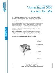
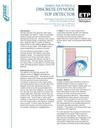
<strong>Product</strong> <strong>Manual</strong> <strong>for</strong> <strong>IonPac</strong> <strong>AS23</strong> amd <strong>IonPac</strong> AG23 <strong>Columns</strong> Page 14 of 325.3 <strong>Product</strong>ion Test ChromatogramsIsocratic elution of inorganic anions and oxyhalides on the <strong>IonPac</strong> <strong>AS23</strong> Analytical Column has been optimized utilizing a carbonate/bicarbonate eluent. By using this eluent, mono- and divalent anions can be isocratically separated and quantitated in a singleinjection. The <strong>IonPac</strong> <strong>AS23</strong> Analytical Column should always be used with the <strong>IonPac</strong> AG23 Guard Column. To guarantee that all<strong>IonPac</strong> <strong>AS23</strong> Analytical <strong>Columns</strong> meet high quality and reproducible per<strong>for</strong>mance specification standards, all columns undergothe following production control test.Sample Volume:4-mm: 25 μL Loop + 0.8 μL Injection valve dead volumeColumn:See ChromatogramEluent: 4.5 mM Na 2CO 3/0.8 mM NaHCO 3Temperature: 30 °CEluent Flow Rate:1.0 mL/min (4-mm)SRS Suppressor:Anion Self-Regenerating Suppressor, ASRS ULTRA II (4-mm)AutoSuppression ® Recycle Modeor MMS Suppressor:Anion MicroMembrane Suppressor, AMMS III (4-mm)MMS Regenerant: 50 mN H 2SO 4or AES Suppressor:Anion Atlas Electrolytic Suppressor, AAESExpected Background Conductivity: 20 - 22 μSLong-term Storage Solution (> 1 week): 100 mM Sodium BicarbonateShort-term Storage Solution (< 1 week): EluentAnalytemg/L (ppm)1. Fluoride 3.02. Chlorite 10.03. Bromate 20.04. Chloride 6.05. Nitrite 15.06. Chlorate 25.07. Bromide 25.08. Nitrate 25.09. Phosphate 40.010. Sulfate 30.0<strong>AS23</strong> (4-mm) only<strong>AS23</strong> (2-mm) only10.0116.0 µSmin234 5 6 7891010.016.0 µSmin1 234 5 6 78910-2.00.0 10.0 20.0 25.0-1.00.0 10.0 20.0 25.0<strong>AS23</strong> (4-mm) + AG23 (4-mm)<strong>AS23</strong> (2-mm) + AG23 (2-mm)10.0116.0 µSmin234 5 6 7891010.0116.0 µSmin234 5 6 78910-2.00.0 10.0 20.0 25.0-1.00.0 10.0 20.0 25.0Figure 1<strong>IonPac</strong> <strong>AS23</strong> <strong>Product</strong>ion Test ChromatogramsDocument No. 065120-05 ©2012 Thermo Fisher Scientific July 2012
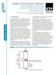
<strong>Product</strong> <strong>Manual</strong> <strong>for</strong> <strong>IonPac</strong> <strong>AS23</strong> amd <strong>IonPac</strong> AG23 <strong>Columns</strong> Page 15 of 325.4 Effect of Temperature on the <strong>AS23</strong> SelectivityThe following chromatograms demonstrate the effect of temperature on the <strong>AS23</strong> selectivity. Monovalent inorganic anions haveslightly shorter retention time and divalent inorganic anions have slightly longer retention time as temperature changes from roomtemperature (21.5 °C) to 35 °C.Sample Loop Volume: 25 µLColumn:<strong>IonPac</strong> <strong>AS23</strong> (4-mm) Analytical Column + <strong>IonPac</strong> AG23 (4-mm) Guard ColumnEluent: 4.5 mM Na 2CO 3/0.8 mM NaHCO 3Temperature:See ChromatogramEluent Flow Rate:1.0 mL/minSRS Suppressor:Anion Self-Regenerating Suppressor, ASRS ULTRA IIAutoSuppression Recycle Modeor AES Suppressor:Atlas Anion Electrolytic Suppressor, AAES,(if eluent suppression required is less than 25 µeq/min)or MMS Suppressor:Anion MicroMembrane Suppressor (AMMS III)MMS Regenerant: 50 mN H 2SO 4Expected Background Conductivity: 20-22 µSAnalytemg/L (ppm)1. Fluoride 3.02. Chlorite 10.03. Bromate 20.04. Chloride 6.05. Nitrite 15.06. Chlorate 25.07. Bromide 25.08. Nitrate 25.09. Phosphate 40.010. Sulfate 30.0835 °C10.01216.0 µSmin4 5 6 71039-2.00.0 10.0 20.0 25.010.01216.0 µSmin4 5 6 7830 °C1039-2.00.0 10.0 20.0 25.0Room Temperature (21.5 °C)10.01216.0 µSmin4 5 6 781039-2.00.0 10.0 20.0 25.0Figure 2Effect of Temperature in <strong>AS23</strong> SelectivityDocument No. 065120-05 ©2012 Thermo Fisher Scientific July 2012
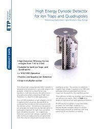
<strong>Product</strong> <strong>Manual</strong> <strong>for</strong> <strong>IonPac</strong> <strong>AS23</strong> amd <strong>IonPac</strong> AG23 <strong>Columns</strong> Page 16 of 325.5 Analysis of Simulated Drinking WaterThe following chromatogram demonstrates the separation of inorganic anions and oxyhalides in a simulated drinking water sample.Sample Loop Volume: 200 µLColumn:<strong>IonPac</strong> <strong>AS23</strong> (4-mm) Analytical Column + <strong>IonPac</strong> AG23 (4-mm) Guard ColumnEluent: 4.5 mM Na 2CO 3/0.8 mM NaHCO 3Temperature: 30 °CEluent Flow Rate:1.0 mL/min.SRS Suppressor:Anion Self-Regenerating Suppressor, ASRS ULTRA II (4-mm)AutoSuppression ® External Modeor MMS Suppressor:Anion MicroMembrane Suppressor, AMMS III (4-mm)MMS Regenerant: 50 mN H 2SO 4or AES Suppressor:Anion Atlas Electrolytic Suppressor, AAESExpected Background Conductivity: 20 - 22 µSAnalytemg/L (ppm)1. Fluoride 1.002. Chlorite 0.013. Bromate 0.0054. Chloride 50.005. Nitrite 0.106. Chlorate 0.017. Bromide 0.018. Nitrate 10.009. Carbonate 50.0010. Phosphate 0.1011. Sulfate 50.000.2000.1000.00010.300 µSmin2 34 56 7891011-0.100-0.2000.0 5.0 10.0 15.0 20.0 25.04300450 µSmin200100111235 6 789 10-500.0 5.0 10.0 15.0 20.0 25.0Figure 3Separation of Simulated Drinking Water on <strong>AS23</strong>Document No. 065120-05 ©2012 Thermo Fisher Scientific July 2012
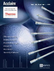
<strong>Product</strong> <strong>Manual</strong> <strong>for</strong> <strong>IonPac</strong> <strong>AS23</strong> amd <strong>IonPac</strong> AG23 <strong>Columns</strong> Page 17 of 325.6 Separation of Anions in Municipal Drinking Water Spiked with Surrogate AnionsThe following chromatogram shows the analysis of a drinking water sample spiked with 1 ppm Malonate and Succinate usingthe <strong>IonPac</strong> <strong>AS23</strong> column and a 200 µL injection loop. Notice the excellent separation of surrogate anions from sulfate.Sample Loop Volume: 200 µLColumn:<strong>IonPac</strong> <strong>AS23</strong> (4-mm) Analytical Column + <strong>IonPac</strong> AG23 (4-mm) Guard ColumnEluent: 4.5 mM Na 2CO 30.8 mM NaHCO 3Temperature: 30 °CEluent Flow Rate:1.0 mL/minSRS Suppressor:Anion Self-Regenerating Suppressor, ASRS ULTRA IIAutoSuppression Recycle Modeor AES Suppressor:Atlas Anion Electrolytic Suppressor, AAES,(if eluent suppression required is less than 25 µeq/min)or MMS Suppressor:Anion MicroMembrane Suppressor (AMMS III)MMS Regenerant: 50 mN H 2SO 4Expected Background Conductivity: 20-23 µSAnalyte1. Fluoride2. Formate3. Chlorite4. Chloride5. Nitrite6. unknown7. Chlorate8. Bromide9. Nitrate10. Carbonate11. Phosphate12. Sulfate13. Malonate14. Succinate15. Oxalate147912130.500 µSmin140.200-0.000235 68101115-0.3000.0 5.0 10.0 15.0 20.0 25.0 30.0 35.00150 µSmin100450121235 6 7 8 9 10 1113 14 15-500.0 5.0 10.0 15.0 20.0 25.0 30.0 35.0Figure 4Separation of Anions in Municipal Drinking Water on <strong>AS23</strong>Document No. 065120-05 ©2012 Thermo Fisher Scientific July 2012
<strong>Product</strong> <strong>Manual</strong> <strong>for</strong> <strong>IonPac</strong> <strong>AS23</strong> amd <strong>IonPac</strong> AG23 <strong>Columns</strong> Page 18 of 325.7 Analysis of Waste Water with the <strong>IonPac</strong> <strong>AS23</strong> ColumnThe following chromatogram shows the analysis of a waste water sample using the <strong>IonPac</strong> <strong>AS23</strong> column. Notice that 2.5 µLinjection loop is used <strong>for</strong> this application due to the high ionic strength of the waste water sample.Sample Loop Volume: 2.5 µLColumn:<strong>IonPac</strong> <strong>AS23</strong> (4-mm) Analytical Column + <strong>IonPac</strong> AG23 (4-mm) Guard ColumnEluent: 4.5 mM Na 2CO 30.8 mM NaHCO 3Temperature: 30 °CEluent Flow Rate:1.0 mL/minSRS Suppressor:Anion Self-Regenerating Suppressor, ASRS ULTRA IIAnalytemg/L (ppm)AutoSuppression Recycle Mode1. Acetate 877.82. Formate 183.23. Chloride 61.84. Nitrite 0.65. Chlorate 213.86. Nitrate 1.57. Phosphate 1.48. Sulfate 1211.19. Unknown NQ**NQ: Not Quantified12 358 92.00 µSmin1.501.000.5046 7-0.200.0 5.0 10.0 15.0 20.0 25.0 30.0 35.050.037.525.012.51 234560.0 µSmin86 79-5.00.0 5.0 10.0 15.0 20.0 25.0 30.0 35.0Figure 5Analysis of Waste Water with <strong>AS23</strong>Document No. 065120-05 ©2012 Thermo Fisher Scientific July 2012
<strong>Product</strong> <strong>Manual</strong> <strong>for</strong> <strong>IonPac</strong> <strong>AS23</strong> amd <strong>IonPac</strong> AG23 <strong>Columns</strong> Page 19 of 325.8 Gradient Separation of Environmental Anions with the <strong>IonPac</strong> <strong>AS23</strong> ColumnThe following chromatogram demonstrates that the <strong>IonPac</strong> <strong>AS23</strong> is a highly hydroxide-selective column. Notice theseparation of a variety of environmental anions using the <strong>IonPac</strong> <strong>AS23</strong> column and a potassium hydroxide gradient.Sample Loop Volume: 10 µLColumn:<strong>IonPac</strong> <strong>AS23</strong> (4-mm) Analytical Column + <strong>IonPac</strong> AG23 (4-mm) Guard ColumnEluent:Potassium Hydroxide: 5 mM from 0 to 5 min, 5-30 mM from 5 to 15 min,30-40 mM from 15 to 30 min.Eluent Source:EGC II KOH with CR-ATCTemperature: 30 °CEluent Flow Rate:1.0 mL/minSRS Suppressor:Anion Self-Regenerating Suppressor, ASRS ULTRA IIAutoSuppression Recycle ModeAnalytemg/L (ppm)1. Fluoride 22. Acetate 103. Butyrate 104. Formate 105. Chlorite 106. Bromate 107. Chloride 58. Nitrite 109. Chlorate 1010. Bromide 1011. Nitrate 1012. Carbonate 2013. Sulfate 1014. Selenate 1015. Oxalate 1016. Phthalate 2017. Phosphate 2018. Chromate 2019. Iodide 2020. Arsenate 2021. Citrate 2022. Thiocyanate 2023. Perchlorate 306.004.002.00123456788.00 µSmin9 10 11121314151617 18 192021 2223-1.000.0 5.0 10.0 15.0 20.0 25.0 30.0 35.0Figure 6Separation of Environmental Anions with <strong>AS23</strong>Document No. 065120-05 ©2012 Thermo Fisher Scientific July 2012
<strong>Product</strong> <strong>Manual</strong> <strong>for</strong> <strong>IonPac</strong> <strong>AS23</strong> amd <strong>IonPac</strong> AG23 <strong>Columns</strong> Page 21 of 326.1 High Back Pressure6.1.1 Finding the Source of High System PressureTotal system pressure <strong>for</strong> the <strong>IonPac</strong> AG23 (4-mm) Guard Column plus the <strong>AS23</strong> (4-mm) Analytical Column when using the testchromatogram conditions should be equal or less than 2,100 psi. If the system pressure is higher than 2,100 psi, it is advisable todetermine the cause of the high system pressure. The system should be operated with a High-Pressure In-Line Filter (P/N 044105)which is positioned between the Gradient Pump pressure transducer and the injection valve. Make sure you have one in place andthat it is not contaminated.A. Make sure that the pump is set to the correct eluent flow rate. Higher than recommended eluent flow rates will causehigher pressure. Measure the pump flow rate if necessary with a stop watch and graduated cylinder.B. Determine which part of the system is causing the high pressure. High pressure could be due to a plugged tubingor tubing with collapsed walls, an injection valve with a clogged port, a column with particulates clogging the bedsupport, a clogged High-Pressure In-Line Filter, the suppressor or the detector cell.To determine which part of the chromatographic system is causing the problem, disconnect the pump eluent line fromthe injection valve and turn the pump on. Watch the pressure; it should not exceed 50 psi. Continue adding systemcomponents (injection valve, column(s), suppressor and detector) one by one, while monitoring the system pressure.The pressure should increase up to a maximum when the Guard and Analytical columns are connected (see Table 7,“Typical <strong>AS23</strong>/AG23 Operating Back Pressures”).The Anion Self-Regenerating Suppressor ULTRA II may add up to 100 psi (0.69 MPa). No other components shouldadd more than 100 psi (0.69 MPa) of pressure. Refer to the appropriate manual <strong>for</strong> cleanup or replacement of the problemcomponent.Table 3Typical <strong>AS23</strong>/AG23 Operating Back PressuresColumn Typical Back Pressure Flow Ratepsi (MPa)mL/min<strong>AS23</strong> 4-mm Analytical 1800(12.41) 1.0AG23 4-mm Guard 300 (2.07) 1.0<strong>AS23</strong> + AG23 4-mm columns 2100 (14.47) 1.0<strong>AS23</strong> 2-mm Analytical 1800(12.41) 0.25AG23 2-mm Guard 300 (2.07) 0.25<strong>AS23</strong> + AG23 2-mm columns 2100 (14.47) 0.25Document No. 065120-05 ©2012 Thermo Fisher Scientific July 2012
<strong>Product</strong> <strong>Manual</strong> <strong>for</strong> <strong>IonPac</strong> <strong>AS23</strong> amd <strong>IonPac</strong> AG23 <strong>Columns</strong> Page 22 of 326.1.2 Replacing Column Bed Support AssembliesIf the column inlet bed support is determined to be the cause of the high back pressure, it should be replaced. To change the inletbed support assembly, refer to the following instructions, using one of the two spare inlet bed support assemblies included in theShip Kit.A. Disconnect the column from the system.B. Carefully unscrew the inlet (top) column fitting. Use two open-end wrenches.C. Remove the bed support. Turn the end fitting over and tap it against a benchtop or other hard, flat surface to removethe bed support and seal assembly. If the bed support must be pried out of the end fitting, use a sharp pointed objectsuch as a pair of tweezers, but be careful that you DO NOT SCRATCH THE WALLS OF THE END FITTING.Discard the old bed support assembly.D. Place a new bed support assembly into the end fitting. Make sure that the end of the column tube is clean and freeof any particulate matter so that it will properly seal against the bed support assembly. Use the end of the column tocarefully start the bed support assembly into the end fitting.<strong>IonPac</strong> <strong>AS23</strong>4-mm <strong>Columns</strong>(P/N)<strong>IonPac</strong> <strong>AS23</strong>2-mm <strong>Columns</strong>(P/N)Analytical Column 064149 064145Guard Column 064147 064143Bed Support Assembly 042955 044689End Fitting 052809 043278CAUTIONIf the column tube end is not clean when inserted into the end fitting, particulate matter may obstruct a properseal between the end of the column tube and the bed support assembly. If this is the case, additional tightening maynot seal the column but instead damage the column tube or the end fitting.E. Screw the end fitting back onto the column. Tighten it fingertight, then an additional 1/4 turn (25 in x lb). Tightenfurther only if leaks are observed.F. Reconnect the column to the system and resume operation.NOTEReplace the outlet bed support ONLY if high pressure persists after replacement of the inlet fitting.Document No. 065120-05 ©2012 Thermo Fisher Scientific July 2012
<strong>Product</strong> <strong>Manual</strong> <strong>for</strong> <strong>IonPac</strong> <strong>AS23</strong> amd <strong>IonPac</strong> AG23 <strong>Columns</strong> Page 23 of 326.2 High Background or NoiseIn a properly working system, the background conductivity level <strong>for</strong> the standard eluent system is shown below:ELUENTEXPECTED BACKGROUND CONDUCTIVITY4.5 mM Na 2CO 3/0.8 mM NaHCO 320 - 22 µS6.2.1 Preparation of EluentsA. Make sure that the eluents and the regenerant are made correctly.B. Make sure that the eluents are made from chemicals with the recommended purity.C. Make sure that the deionized water used to prepare the reagents has a specific resistance of 18.2 megohm-cm.6.2.2 A Contaminated Guard or Analytical ColumnRemove the <strong>IonPac</strong> AG23 Guard and <strong>AS23</strong> Analytical <strong>Columns</strong> from the system. If the background conductivity decreases, thecolumn(s) is (are) the cause of the high background conductivity. Clean or replace the AG23 at the first sign of column per<strong>for</strong>mancedegradation (compared to the original test chromatogram) to eliminate downtime. Clean the column(s) as instructed in “ColumnCleanup” (See, “Column Care”).6.2.3 A Contaminated Anion Trap Column, ATC-3When doing gradient analysis, has the Anion Trap Column, the ATC-3 (2-mm) or the ATC-3 (4-mm) been installed correctly? If ithas not, install one as directed in Section 3.5, Installing the Anion Trap Column, and watch the background conductivity. If thebackground conductivity is now low, this means that the ATC is trapping contaminants from the eluent. The eluents probably havetoo many impurities (see items 1 - 3 above).If the ATC is already installed, remove it. Is the background conductivity still high? If the background conductivity decreases, theATC is the source of the high background conductivity.A. Disconnect either the ATC-3 (2-mm) or the ATC-3 (4-mm) from the injection valve and direct the outlet to waste.B. Flush the ATC with 200 mL of 70 mM Na 2B 4O 7. Use a flow rate of 0.5 mL/min on a 2-mm system or a flow rate of 2.0 mL/min on a 4-mm system.C. Equilibrate the ATC with the strongest eluent used during the gradient run. Use a flow rate of 0.5 mL/min on a 2-mm systemor a flow rate of 2.0 mL/min on a 4-mm system.D. If the problem persists, replace the ATC.6.2.4 Contaminated HardwareTo eliminate the hardware as the source of the high background conductivity, bypass the columns and the Anion Self-RegeneratingSuppressor. Pump deionized water with a specific resistance of 18.2 megohm-cm through the system. The background conductivityshould be less than 2 µS. If it is not, check the detector/conductivity cell calibration by injecting deionized water directly into it.See the appropriate manual <strong>for</strong> details.6.2.5 A Contaminated Anion Self-Regenerating Suppressor, ASRS ULTRA IIThis section describes routine cleanup procedures <strong>for</strong> the Anion Self-Regenerating Suppressors (ASRS ULTRA II) in the case ofcontamination. Consult the Troubleshooting Guide (see Section 4, “Troubleshooting Guide”) to first determine that the system isoperating properly. If the ASRS ULTRA II is determined to be the source of higher than normal back pressure, higher than anticipatedDocument No. 065120-05 ©2012 Thermo Fisher Scientific July 2012
<strong>Product</strong> <strong>Manual</strong> <strong>for</strong> <strong>IonPac</strong> <strong>AS23</strong> amd <strong>IonPac</strong> AG23 <strong>Columns</strong> Page 24 of 32conductivity, decreased suppression capacity or decreased sensitivity, cleaning the membrane may restore the per<strong>for</strong>mance of thesystem. Use the following procedures to clean the membrane.Metal Contaminants or PrecipitatesNOTEThe suppressor voltage is a good indicator of the resistance across the suppressor. Higher resistance may indicatecontamination of the suppressor. For more in<strong>for</strong>mation regarding monitoring the voltage, see Document No. 031814-02, “Removal of Iron Contamination from Electrolytic Suppressors.”A. Turn off the SRS Control unit.B. Disconnect the analytical (and guard) column(s) from the injection valve and the ASRS ULTRA II. Refer to the specificanalytical column <strong>Product</strong> <strong>Manual</strong> <strong>for</strong> column cleanup procedures.C. If you are running in the AutoSuppression External Water Mode, turn off the external water and disconnect the externalwater line from the ASRS ULTRA II REGEN IN port.D. Disconnect the liquid line from the ASRS ULTRA II ELUENT OUT port to the cell at the cell fitting and reconnect it tothe REGEN IN port.E. Connect a temporary line from the priming block or the low-pressure tee on the isocratic or gradient pump to a containerwith a solution of 0.2 M oxalic acid. Pump this solution through the ASRS-ULTRA (4-mm) at 1-2 mL/min <strong>for</strong> 30 minutes.For 2-mm systems pump this solution through the ASRS-ULTRA (2-mm) at 0.25-0.50 mL/min <strong>for</strong> 30 minutes.NOTEBypassing internal pump manifolds when temporarily pumping high concentration cleaning solutions significantlyreduces the time required to reequilibrate the system to low concentration eluents.F. Flush the ASRS ULTRA II with deionized water <strong>for</strong> 10 minutes.G. Per<strong>for</strong>m steps A - D of the procedure in Section 4.1, “Small Analyte Peak Areas.”H. Turn on the SRS Control unit <strong>for</strong> the AutoSuppression Recycle or External Water Modes of operation. Ensure that theSRS Control unit is off <strong>for</strong> the Chemical Suppression Mode of operation.I. Flush the ASRS ULTRA II with eluent <strong>for</strong> 10 minutes.J. Reinstall the analytical (and guard) column(s). Begin pumping eluent through the system at the flow rate required <strong>for</strong>your analysis and equilibrate the system.6.2.6 A Contaminated Anion MicroMembrane Suppressor, AMMS IIIA. Check the regenerant flow rate at the REGEN OUT port of the AMMS. For the example isocratic applications, this flowrate should be 3 - 5 mL/min.B. Check the eluent flow rate. In general, the eluent flow rate <strong>for</strong> 4-mm applications, it should be 1.2 mL/min. Refer to theAnion MicroMembrane Suppressor <strong>Product</strong> <strong>Manual</strong> (Document No. 034449-02) <strong>for</strong> assistance in determining that theeluent is within suppressible limits.C. If you are using an AutoRegen Accessory with the SRS (in the Chemical Suppression Mode) or the MMS, preparefresh regenerant solution. Test both the suppressor and the AutoRegen Regenerant Cartridge <strong>for</strong> contamination.Document No. 065120-05 ©2012 Thermo Fisher Scientific July 2012
<strong>Product</strong> <strong>Manual</strong> <strong>for</strong> <strong>IonPac</strong> <strong>AS23</strong> amd <strong>IonPac</strong> AG23 <strong>Columns</strong> Page 25 of 321. If the background conductivity is high after preparing fresh regenerant and bypassing the AutoRegen RegenerantCartridge, you probably need to clean or replace your SRS or MMS.2. If the background conductivity is low when freshly prepared regenerant is run through the SRS or MMS withoutan AutoRegen Accessory in-line, test the AutoRegen Regenerant Cartridge to see if it is expended. Connect thefreshly prepared regenerant to the AutoRegen Regenerant Cartridge. Pump approximately 200 mL of regenerantthrough the AutoRegen Regenerant Cartridge to waste be<strong>for</strong>e recycling the regenerant back to the regenerantreservoir. If the background conductivity is high after placing the AutoRegen Accessory in-line, you probably needto replace the AutoRegen Regenerant Cartridge. Refer to the “AutoRegen Regenerant Cartridge Refill <strong>Product</strong><strong>Manual</strong>” (Document No. 032852) <strong>for</strong> assistance.6.2.7 A Contaminated Anion Atlas Electrolytic Suppressor, AAESMetal Contaminants or PrecipitatesA. Turn off the power to the AAES.B. Disconnect the analytical (and guard) column(s) from the injection valve and the AAES. Refer to the specific analyticalcolumn <strong>Product</strong> <strong>Manual</strong> <strong>for</strong> column cleanup procedures.C. If you are running in the AutoSuppression External Water Mode, turn off the external water and disconnect the externalwater line from the AAES REGEN IN port.D. Disconnect the liquid line from the AAES ELUENT OUT port to the cell at the cell fitting and reconnect it to the REGENIN port.E. Connect a temporary line from the priming block or the low-pressure tee on the isocratic or gradient pump to a containerwith a solution of 0.5 M oxalic acid. Pass 60 mL of this solution through the AAES using the Trap Column / SuppressorClean-up Kit (P/N 059649) or pump this solution through the AAES at 2.0 mL/min <strong>for</strong> 30 minutes.NOTEBypassing internal pump manifolds when temporarily pumping high concentration cleaning solutions significantlyreduces the time required to re-equilibrate the system to low concentration eluents.F. Flush the AAES with deionized water at 2 mL/min <strong>for</strong> 30 minutes.G. Reinstall the AAES according to procedures in Section 4.2.1, “Eluent and Regenerant Flow Path Connections in theAutoSuppression Recycle Mode Operation” or Section 4.3.1, “Eluent Flow Path Connections in the AutoSuppressionExternal Water Mode Operation” and resume operation.Organic ContaminantsA. Turn off the power to the AAES.B. Disconnect the analytical (and guard) column(s) from the injection valve and the AAES. Refer to the specific analyticalcolumn <strong>Product</strong> <strong>Manual</strong> <strong>for</strong> column cleanup procedures.C. If you are running in the AutoSuppression External Water Mode, turn off the external water and disconnect the externalwater line from the AAES REGEN IN port. If you are running in the AutoSuppression Recycle Mode, proceed to D.D. Disconnect the liquid line from the AAES ELUENT OUT port to the cell at the cell fitting and reconnect it to the REGENIN port.E. Connect a temporary line from the priming block or the low-pressure tee on the isocratic or gradient pump to a containerDocument No. 065120-05 ©2012 Thermo Fisher Scientific July 2012
<strong>Product</strong> <strong>Manual</strong> <strong>for</strong> <strong>IonPac</strong> <strong>AS23</strong> amd <strong>IonPac</strong> AG23 <strong>Columns</strong> Page 26 of 32with a solution of freshly prepared 10% 1.0 M H 2SO 4/90% acetonitrile. H 2SO 4/acetonitrile solutions are not stable duringlong term storage so this cleanup solution must be made immediately be<strong>for</strong>e each column cleanup. Alternatively, it canbe proportioned from 1 bottle containing 1.0 M H 2SO 4and another bottle containing 100% acetonitrile. Pass 60 mL ofthis solution through the AAES using the Trap Column / Suppressor Clean-up Kit (P/N 059649) or pump this solutionthrough the AAES at 1.0 mL/min <strong>for</strong> 60 minutes.NOTEBypassing internal pump manifolds when temporarily pumping high concentration cleaning solutions significantlyreduces the time required to re-equilibrate the system to low concentration eluents.F. Flush the AAES with deionized water at 2 mL/min <strong>for</strong> 30 minutes.G. Reinstall the AAES according to procedures in Section 4.2.1, “Eluent and Regenerant Flow Path Connections in theAutoSuppression Recycle Mode Operation” or Section 4.3.1, “Eluent Flow Path Connections in the AutoSuppressionExternal Water Mode Operation” and resume operation.6.3 Poor Peak ResolutionPoor peak resolution can also be due to any or all of the following factors:6.3.1 Loss of Column EfficiencyA. Check to see if headspace has developed in the guard or analytical column. This is usually due to improper use of thecolumn such as submitting it to high pressures. Remove the column’s top end fitting (see Section 6.1.2, “ReplacingColumn Bed Support Assemblies”). If the resin does not fill the column body all the way to the top, it means that theresin bed has collapsed, creating a headspace. The column must be replaced.B. Extra-column effects can result in sample band dispersion, making the peaks' elution less efficient. Make sure youare using PEEK tubing with an ID of no greater than 0.010" <strong>for</strong> 4-mm systems or no greater than 0.005" <strong>for</strong> 2-mm systemsto make all eluent liquid line connections between the injection valve and the detector cell inlet. Cut the tubing lengthsas short as possible. Check <strong>for</strong> leaks.6.3.2 Poor Resolution Due to Shortened Retention TimesEven with adequate system and column efficiency, resolution of peaks will be compromised if analytes elute too fast.A. Check the flow rate. See if the eluent flow rate is equivalent to the flow rate specified by the analytical protocol. Measurethe eluent flow rate after the column using a stopwatch and graduated cylinder.B. Check to see if the eluent compositions and concentrations are correct. An eluent that is too concentrated will causethe peaks to elute faster. Prepare fresh eluent. If you are using a gradient pump to proportion the eluent, componentsfrom two or three different eluent reservoirs, the resulting eluent composition may not be accurate enough <strong>for</strong> theapplication. Use one reservoir containing the correct eluent composition to see if this is the problem. This may be aproblem when one of the proportioned eluents is less than 5%.C. Column contamination can lead to a loss of column capacity. This is because all of the anion exchange sites will no longerbe available <strong>for</strong> the sample ions. For example, polyvalent anions from the sample or metals may concentrate on the column.Refer to “Column Cleanup” (See, “Column Care”), <strong>for</strong> recommended column cleanup procedures.Possible sources of column contamination are impurities in chemicals and in the deionized water used <strong>for</strong> eluents orcomponents of the sample matrix. Be especially careful to make sure that the recommended chemicals are used. Thedeionized water should have a specific resistance of 18.2 megohm-cm.Document No. 065120-05 ©2012 Thermo Fisher Scientific July 2012
<strong>Product</strong> <strong>Manual</strong> <strong>for</strong> <strong>IonPac</strong> <strong>AS23</strong> amd <strong>IonPac</strong> AG23 <strong>Columns</strong> Page 27 of 32D. Diluting the eluent will improve peak resolution, but will also increase the analytes’ retention times. If a 10% dilutionof the eluent is not sufficient to obtain the desired peak resolution, or if the resulting increase in retention times isunacceptable, clean the column (see, “Column Cleanup” in “Column Care”).After cleaning the column, reinstall it in the system and let it equilibrate with eluent <strong>for</strong> about 30 minutes. No water washis necessary. The column is equilibrated when consecutive injections of the standard give reproducible retention times.The original column capacity should be restored by this treatment, since the contaminants should be eluted from thecolumn. If you need assistance in solving resolution problems, contact the North America Technical Call Center at 1-800-DIONEX-0 (1-800-346-6390) or the nearest <strong>Dionex</strong> Office (see, “<strong>Dionex</strong> Worldwide Offices”).6.3.3 Loss of Front End ResolutionIf poor resolution or efficiency is observed <strong>for</strong> the peaks eluting near the system void volume compared to the later eluting peaks,check the following:A. Improper eluent concentration may be the problem. Remake the eluent as required <strong>for</strong> your application. Ensure that thewater and chemicals used are of the required purity.B. Column overloading may be the problem. Reduce the amount of sample ions being injected onto the analytical columnby either diluting the sample or injecting a smaller volume onto the column.C. Sluggish operation of the injection valve may be the problem. Check the air pressure and make sure there are no gasleaks or partially plugged port faces. Refer to the valve manual <strong>for</strong> instructions.D. Improperly swept out volumes anywhere in the system prior to the guard and analytical columns may be the problem.Swap components, one at a time, in the system prior to the analytical column and test <strong>for</strong> front-end resolution after everysystem change.6.3.4 Spurious PeaksA. The columns may be contaminated. If the samples contain an appreciable level of polyvalent ions and the column is usedwith a weak eluent system, the retention times <strong>for</strong> the analytes will then decrease and be spurious, inefficient (broad)peaks that can show up at unexpected times. Clean the column as indicated in “Column Cleanup” (See, “Column Care”).If you need assistance in determining the best way to clean strongly retained solutes in your specific sample matrix fromthe <strong>IonPac</strong> <strong>AS23</strong> columns, contact the North America Technical Call Center at 1-800-DIONEX-0 (1-800-346-6390) or thenearest <strong>Dionex</strong> Office (see, “<strong>Dionex</strong> Worldwide Offices”).B. The injection valve may need maintenance. When an injection valve is actuated, the possibility of creating a baselinedisturbance exists. This baseline upset can show up as a peak of varying size and shape. This will occur when the injectionvalve needs to be cleaned or retorqued (see valve manual). Check to see that there are no restrictions in the tubingconnected to the valve. Also check the valve port faces <strong>for</strong> blockage and replace them if necessary. Refer to the Valve<strong>Manual</strong> <strong>for</strong> troubleshooting and service procedures. Small baseline disturbances at the beginning or at the end of thechromatogram can be overlooked as long as they do not interfere with the quantification of the peaks of interest.Document No. 065120-05 ©2012 Thermo Fisher Scientific July 2012
<strong>Product</strong> <strong>Manual</strong> <strong>for</strong> <strong>IonPac</strong> <strong>AS23</strong> amd <strong>IonPac</strong> AG23 <strong>Columns</strong> Page 28 of 32For DX-300 systems equipped with a Rheodyne Microinjection Valve, Model 9126 (<strong>Dionex</strong> P/N 044697), consult theaccompanying manual <strong>for</strong> service instructions.6.3.5 Poor Resolution of Only Phosphate and SulfateA. Causes1. Sodium carbonate is contaminated with sodium hydroxide,2. Inadequate equilibration after use of an alkaline buffer or hydroxide eluent,3. Sodium carbonate was dried at temperatures > 110°C.B. Action1. Use <strong>Dionex</strong> <strong>AS23</strong> Eluent Concentrate (P/N 064161).2. Use a high purity sodium carbonate salt.3. Dry the sodium carbonate at a lower temperature. See section 4.3.1 and section 5.1.Document No. 065120-05 ©2012 Thermo Fisher Scientific July 2012
<strong>Product</strong> <strong>Manual</strong> <strong>for</strong> <strong>IonPac</strong> <strong>AS23</strong> amd <strong>IonPac</strong> AG23 <strong>Columns</strong> Page 29 of 32APPENDIX A - COLUMN CAREA.1 Recommended Operating PressureOperating a column above its recommended pressure limit can cause irreversible loss of column per<strong>for</strong>mance. Themaximum recommended operating pressure <strong>for</strong> <strong>IonPac</strong> <strong>AS23</strong> columns is 3,000 psi (20.68 MPa).A.2 Column Start-UpThe column is shipped using the column test eluent as the storage solution.Prepare the eluent shown on the test chromatogram, install the column in the chromatography module and test the columnper<strong>for</strong>mance under the conditions described in the test chromatogram. Continue making injections of the test standarduntil consecutive injections of the standard give reproducible retention times. Equilibration is complete when consecutiveinjections of the standard give reproducible retention times.A.3 Column StorageFor short-term storage (< 1 week), use Eluent, <strong>for</strong> long-term storage (> 1 week), use 100 mM Sodium Bicarbonate <strong>for</strong> thecolumn storage solution. Flush the column <strong>for</strong> a minimum of 10 minutes with the storage solution. Cap both endssecurely, using the plugs supplied with the column.A.4 Column CleanupThe following column cleanup protocols have been divided into three general isocratic protocols to remove acid-soluble,base-soluble, or organic contaminants. They can be combined into one gradient protocol if desired; however, thefollowing precautions should be observed.WARNINGAlways ensure that the cleanup protocol used does not switch between eluents which may create highpressure eluent interface zones in the column.High pressure zones can disrupt the uni<strong>for</strong>mity of the packing of the column bed and irreversibly damagethe per<strong>for</strong>mance of the column.High pressure zones in the column can be created by pumping successive eluents through the column thatare not miscible, that have eluent components in one eluent that will precipitate out in the other eluent orby using an acid eluent followed by a base eluent which may create a neutralization pressure band.The precipitation of the salts in solvents during column rinses can result in very high pressure zones.High viscosity mixing zones can be created between two eluents having solvents with a very high energy ofmixing.When in doubt, always include short column rinse steps to reduce the solvent content of the eluent to < 5% levels andthe ionic strength of the eluent to < 50 mM levels to avoid creating high pressure zones in the column that may disruptthe uni<strong>for</strong>mity of the column packing.Document No. 065120-05 ©2012 Thermo Fisher Scientific July 2012
<strong>Product</strong> <strong>Manual</strong> <strong>for</strong> <strong>IonPac</strong> <strong>AS23</strong> amd <strong>IonPac</strong> AG23 <strong>Columns</strong> Page 30 of 32ContaminationHydrophilicContamination of LowValenceA.4.1 Choosing the Appropriate Cleanup SolutionSolutionConcentrated carbonate solutions such as a 10X concentrate of the most concentrated eluent used in theapplication is sufficient to remove hydrophilic contamination of low valence.High ValenceHydrophilic IonsContaminationMetal ContaminationConcentrated acid solutions such as 1 to 3 M HCl will remove high valence hydrophilic ions by ionsuppression and elution by the chloride ion.Metal contamination often results in asymmetric peak shapes and/or variable analyte recoveries. Forexample, iron or aluminum contamination often results in tailing of sulfate and phosphate. Aluminumcontamination can also result in low phosphate recoveries.Concentrated acid solutions such as 1 to 3 M HCl remove a variety of metals. If after acid treatment, thechromatography still suggests metal contamination, treatment with chelating acids such as 0.2 M oxalic acidis recommended.Nonionic andHydrophobicContaminationOrganic solvents can be used alone if the contamination is nonionic and hydrophobic. The degree ofnonpolar character of the solvent should be increased as the degree of hydrophobicity of the contaminationwithin the range of acceptable solvents.Ionic and HydrophobicContaminationConcentrated acid solutions such as 1 to 3 M HCl can be used with compatible organic solvents to removecontamination that is ionic and hydrophobic. The acid suppresses ionization and ion exchange interactionsof the contamination with the resin.A frequently used cleanup solution is 200 mM HCl in 80% acetonitrile. This solution must be madeimmediately be<strong>for</strong>e use because the acetonitrile will decompose in the acid solution during long term storage.A.4.2 Column Cleanup ProcedureUse the following cleanup procedures to clean the AG23 and <strong>AS23</strong>.a) Prepare a 500 mL solution of the appropriate cleanup solution using the guidelines in, "Choosing theAppropriate Cleanup Solution".b) Disconnect the ASRS ULTRA II, AAES, or AMMS III from the <strong>IonPac</strong> <strong>AS23</strong> Analytical Column.c) If your system is configured with both a guard column and an analytical column, reverse the order of theguard and analytical column in the eluent flow path.d) Double check that the eluent flows in the direction designated on each of the column labels.When cleaning an analytical column and a guard column in series, ensure that the guard column isplaced after the analytical column in the eluent flow path. If not, the contaminants that haveaccumulated on the guard column can be eluted onto the analytical column and irreversibly damage it.CAUTIONIf in doubt, clean each column separately.e) Set the pump flow rate to 1.0 mL/min <strong>for</strong> an <strong>AS23</strong> 4-mm Analytical or Guard Column or set the pump flowrate to 0.25 mL/min <strong>for</strong> an <strong>AS23</strong> 2-mm Analytical or Guard Column.f) Rinse the column <strong>for</strong> 10 minutes with deionized water be<strong>for</strong>e pumping the chosen cleanup solution overthe column.g) Pump the cleanup solution through the column <strong>for</strong> at least 60 minutes.h) Rinse the column <strong>for</strong> 10 minutes with deionized water be<strong>for</strong>e pumping eluent over the column.i) Equilibrate the column(s) with eluent <strong>for</strong> at least 60 minutes be<strong>for</strong>e resuming normal operation.j) Reconnect the ASRS ULTRA II, AAES, or AMMS III to the <strong>AS23</strong> Analytical Columnk) Place the guard column in line between the injection valve and the analytical column if your system wasoriginally configured with a guard column.Document No. 065120-05 ©2012 Thermo Fisher Scientific July 2012
<strong>Product</strong> <strong>Manual</strong> <strong>for</strong> <strong>IonPac</strong> <strong>AS23</strong> amd <strong>IonPac</strong> AG23 <strong>Columns</strong> Page 31 of 32APPENDIX B - CONFIGURATIONCONFIGURATION2-mmTable 1Configuration4-mmEluent Flow RateSRS SuppressorMMS SuppressorAAE S uppressorInjection LoopSystem Void VolumePumpsDetectors0.30 mL/min 1.20 mL/minASRS ULTRA II (2-mm) (P/N 061562) ASRS ULTRA II (4-mm) (P/N 061561)AMMS III (2-mm) (P/N 056751) AMMS III (4-mm) (P/N 056750)AAES (P/N 056116) AAES (P/N 056116)2 - 15 µL 10-50 µLRheodyne Microinjection Valve (P/N 044697) <strong>for</strong> full loop injections
<strong>Product</strong> <strong>Manual</strong> <strong>for</strong> <strong>IonPac</strong> <strong>AS23</strong> amd <strong>IonPac</strong> AG23 <strong>Columns</strong> Page 32 of 32Table 2Tubing Back PressuresColor<strong>Dionex</strong>P/NID Inches ID cm VolumemL/cmBack Presurepsi/ft at 1mL/minBack Presurepsi/ft at 0.25mL/minBack Presurepsi/cm at 1mL/minGreen 044777 0.030 0.076 4.560 0.086 0.021 0.003Orange 042855 0.020 0.051 2.027 0.435 0.109 0.015Blue 049714 0.013 0.033 0.856 2.437 0.609 0.081Black 042690 0.010 0.025 0.507 6.960 1.740 0.232Red 044221 0.005 0.013 0.127 111.360 27.840 3.712Yellow 049715 0.003 0.008 0.046 859.259 214.815 28.642Document No. 065120-05 ©2012 Thermo Fisher Scientific July 2012