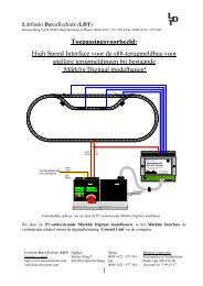
TurnTable-Decoder TT-DEC-R - LDT
TurnTable-Decoder TT-DEC-R - LDT
TurnTable-Decoder TT-DEC-R - LDT

You also want an ePaper? Increase the reach of your titles
YUMPU automatically turns print PDFs into web optimized ePapers that Google loves.
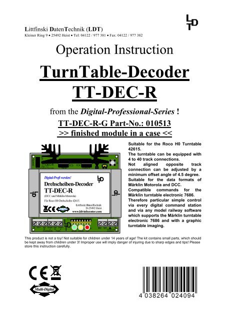
<strong>TT</strong>-<strong>DEC</strong>-R – ManualIndex:Page1. Preface / Safety Instruction 22. Selecting the available turntable (old or new version) 23. Alterations on the Roco turntable 33.1. Free-wheeling diode soldering 33.2. Motor cable soldering 53.3. Bridge track contact isolation 74. Correct position of the turntable sliding switches and the settingor removing of the matching jumper JP1 of the <strong>TT</strong>-<strong>DEC</strong>-R 85. <strong>TT</strong>-<strong>DEC</strong>-R connection to the digital layout and to the turntable 85.1. <strong>TT</strong>-<strong>DEC</strong>-R connection to the digital layout 85.2. <strong>TT</strong>-<strong>DEC</strong>-R connection to the turntable 105.2.1. <strong>TT</strong>-<strong>DEC</strong>-R connection to old version 105.2.2. <strong>TT</strong>-<strong>DEC</strong>-R connection to new version 116. Turntable-<strong>Decoder</strong> <strong>TT</strong>-<strong>DEC</strong>-R programming 126.1. Basic address and data format programming 126.2. Turning direction testing 136.3. Track connection programming 136.4. Bridge track polar reversal (only 2-conductor mode) 166.5. Turning speed adjustment 186.6. Reference track synchronizing 196.7. Special function: Turntable test / Factory setting 196.8. Programming- and Control-Table 207. Feedback reports 218. Assembly plan 23- 1 -
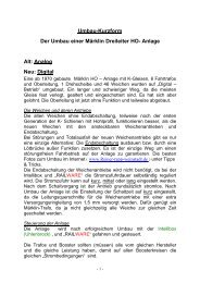
<strong>TT</strong>-<strong>DEC</strong>-R – Manual1. Preface / Safety Instruction:You have purchased the <strong>TurnTable</strong>-<strong>Decoder</strong> <strong>TT</strong>-<strong>DEC</strong>-R for your model railway layoutsupplied within the assortment of Littfinski DatenTechnik (<strong>LDT</strong>).We are wishing you having a good time for the application of this product!The purchased unit comes with 24 month guarantee (validity for the finished moduleand finished module in a case only).• Please read this instruction careful. For damages caused by disregarding thisinstruction the right of claiming guarantee will expire. No liability will be takenover for resultant damages. You can download this manual as a PDF-file withcolored pictures from the area “Downloads” at our Web-Site. The file can beopened with the Acrobat Reader.• Attention: Carry out any connections only with disconnected model railwaylayout (switch-off the transformers or disconnect the main plug).2. Selecting the available turntable (old or new version):The Roco H0 Turntable 42615 is available within two different versions. Thedifference between the two versions is the supplied 8-poles flat ribbon cable and thesupplied pc-board for the under-floor drive of the turntable. For identification whichversion you own please have a look at the bottom of the turntable. If there is a boreat the protection cover as per the right sketch it will be the new version. Without abore at the protection cover it will be the old version as shown to the left.schwarzblackschwarzblackBohrung für zusätzlicheSchraubverbindungbore for additionalscrewed connectionR OC OR OC O0 10 1Roco Drehscheibe 42615 alte VarianteRoco Turntable 42615 old versionRoco Drehscheibe 42615 neue VarianteRoco Turntable 42615 new version- 2 -
<strong>TT</strong>-<strong>DEC</strong>-R – Manual3. Alterations on the Roco Turntable:• Important Information: Any alteration on the Roco Turntable 42615 have tobe completed before the Turntable-<strong>Decoder</strong> <strong>TT</strong>-<strong>DEC</strong>-R gets into first operation.An operation of the Turntable-<strong>Decoder</strong> <strong>TT</strong>-<strong>DEC</strong>-R before the electrical changeshave been completed (soldering the free-wheel diode and the drive-motorcables) can eventually damage the Turntable-<strong>Decoder</strong> <strong>TT</strong>-<strong>DEC</strong>-R and as wellyour turntable.After completing the electrical alterations the Roco Turntable 42615 can not becontrolled anymore by the Roco-Turntable remote control unit.3.1. Free-wheeling diode soldering:The free-wheeling diode 1N4003 which is attached to each supplied Turntable-<strong>Decoder</strong> <strong>TT</strong>-<strong>DEC</strong>-R has to be soldered onto the pc-board of the under-floor drive toprevent the interference of the switching voltage of the interlock coil.For this procedure please take off the protection cover of the under-floor drivemechanic as described at the Roco Manual for the turntable and read the section“Maintenance of the drive”.After removing the protection cover you can see the pc-board and the under-floordrive of the old version shown at the left draft and the new version at the right.schwarzblackschwarzblack0 L42615-a110 142615-A11Roco Drehscheibe 42615 alte VarianteRoco Turntable 42615 old versionRoco Drehscheibe 42615 neue VarianteRoco Turntable 42615 new versionThe detailed images on the next page show the wiring of the under-floor drive to thepc-board before the alteration. The old version is shown at the left and the newversion at the right.- 3 -
<strong>TT</strong>-<strong>DEC</strong>-R – Manual42615-a11Roco Drehscheibe 42615 alte VarianteRoco Turntable 42615 old version15-A11Roco Drehscheibe 42615 neue VarianteRoco Turntable 42615 new versionPlease solder the diode 1N4003 onto the soldering terminals of the pc-board asshown at the two detailed images.Before soldering please shorten the connection wires of the diode 1N4003 to alength of about 1 cm and bend both wires careful at 90 degree just after the diodebody.The diode 1N4003 has on one connection wire a printed ring (called cathode ring) forthe correct assembly direction.The diode 1N4003 has been correct soldered at the old version if the cathode ringshows to the right respectively direct to the track connections (image left).At the new turntable version is the soldered position of the diode 1N4003 correct ifthe cathode ring shows to the bottom to the worm drive (image right).42615-a11Diode1N4003Roco Drehscheibe 42615 alte VarianteRoco Turntable 42615 old version15-A11Diode1N4003Roco Drehscheibe 42615 neue VarianteRoco Turntable 42615 new version- 4 -
<strong>TT</strong>-<strong>DEC</strong>-R – Manual3.2. Motor cable soldering:Each Turntable-<strong>Decoder</strong> <strong>TT</strong>-<strong>DEC</strong>-R will be supplied together with a 2m 2-poles motorconnection cable. On one side is the cable is equipped with two inductors.Originally is the motor of the under-floor drive connected to the pc-board via twowires. Remove this two cables by unsolder them from the motor connection and fromthe pc-board.After unsoldering the two wires you should solder the motor-cable (attached to eachturntable-<strong>Decoder</strong> <strong>TT</strong>-<strong>DEC</strong>-R) onto both motor connections as described withinsection 3.2.1.If the motor is not connected by two cables to the printed circuit board you own oneof the oldest Roco version of the HO Turntable 42615. On this oldest version themotor receives the power supply via two contact springs which are riveted onto thepc-board and give contact by pressure against two contact plates at the motor. Theleft picture shows the motor-connection of the oldest version before alteration.Motoranschluss vor Umbaumotor connection before rebuildingErster Umbauschrittfirst step of rebuildingAt the first step of alteration shown within picture right the two spring-contacts shallbe bent down to the PC-board. Now there is no electrical contact to the two contactsat the motor.At the second alteration step shown on the next page the motor cable (attached toeach Turntable-<strong>Decoder</strong> <strong>TT</strong>-<strong>DEC</strong>-R) shall be soldered onto the motor. Eachconnection wire of one choke shall be soldered onto one of the two hexagonalcontact plates of the motor.Which of the two chokes soldered to one of the two contact plates does no matter.- 5 -
<strong>TT</strong>-<strong>DEC</strong>-R – ManualTo prevent an electrical contact to the PC-board by vibration of the motor pleasestick an isolation tape around the motor and over the two contact plates. Theisolation tape should be long enough to isolate the contact plates as well under thepc-board.Motorkabelmotor cableMotorkabelmotor cableDrosselnInductorsDrosselnInductorsIsolierbandInsulating tapeZweiter Umbauschrittsecond step of rebuildingMotoranschluss nach Umbaumotor connection after rebuildingAfter completion of alteration of the oldest Roco HO Turntable 42615 versiontighten the safety cover of the turntable as described within section 3.2.2.3.2.1. Now solder the new motor cable to the two motor connections. Eachconnection wire of the inductors has to be soldered to one of the two motorconnections of the under-floor drive.Which of the two inductors soldered to which of the two motor connections does nomatter.DrosselnInductorsMotorkabelmotor cableDrosselnInductorsMotorkabelmotor cable42615-a11Diode1N4003Roco Drehscheibe 42615 alte VarianteRoco Turntable 42615 old version15-A11Diode1N4003Roco Drehscheibe 42615 neue VarianteRoco Turntable 42615 new version- 6 -
<strong>TT</strong>-<strong>DEC</strong>-R – Manual3.2.2. Before replacing the protection cover of the turntable as described within theRoco Manual for the turntable within the section “Maintenance of the drive” and aftercompletion of the alteration you have to feed the motor cable through the opening onthe protection cover near the motor connections.Each Turntable-<strong>Decoder</strong> <strong>TT</strong>-<strong>DEC</strong>-R will be supplied together with a cable fastener forstrain relief and for securing the motor cable onto the lower latch of the coveropening.The pictures on the following page show both turntable versions after attaching theprotection cover including the motor cable after the completion of the electricalalteration.schwarzblackschwarzblackMotorkabelmotor cableMotorkabelmotor cableR OC OR OC O0 10 1Roco Drehscheibe 42615 alte VarianteRoco Turntable 42615 old versionRoco Drehscheibe 42615 neue VarianteRoco Turntable 42615 new version3.3. Bridge track contact isolation:At the supply status the Roco turntable 42615 contains on each bridge track endtwo slide contacts for the connection to the selected track.These slide contacts have to be removed or isolated before the turntableDecode <strong>TT</strong>-<strong>DEC</strong>-R will be set into function.For removing or isolating the four sliding contacts you should remove severalaccess tracks respectively blind tracks as described at the manual for the RocoTurntable 42615.If you do not want to remove the four sliding contacts with a small side cutter youwill have the possibility to lower the contacts to assure that no electrical contact tothe track connections is possible.For this action please bend the sliding contacts carefully down and slide a little pieceof cable insulation between the sliding contact and the bridge track. The slidingcontact will be permanently lowered and can not provide any electrical contact tothe rails of the access tracks.- 7 -
<strong>TT</strong>-<strong>DEC</strong>-R – Manual4. Correct position of the turntable sliding switches and the setting orremoving of the matching jumper JP1 of the <strong>TT</strong>-<strong>DEC</strong>-R:There are two sliding switches at the lower side of the turntable.One of the two sliding switches is market with a “0” and ”1”. For the operation inconnection to the Turntable-<strong>Decoder</strong> <strong>TT</strong>-<strong>DEC</strong>-R this switch has always to be set ontoposition “1”.The second slide switch is marked with the symbol “=” and “~”. The marking “=”indicates the setting for the operation with the 2-conductor bridge track system andthe marking “~” indicates the setting for the 3-conductor system.Now select the correct switch position in accordance to the used track conductorsystem.Additional information can be found within the Roco Manual for the turntable at thesection “Selecting the driving current system”.If you use the turntable at the 2-conductor system (sliding switch at the turntable inposition “=”) please remove the jumper JP1 at the <strong>TT</strong>-<strong>DEC</strong>-R. You can find this jumperat the right between the case cover and the heat sink of the Turntable-<strong>Decoder</strong> <strong>TT</strong>-<strong>DEC</strong>-R.If the operation of the turntable is used in a 3-conductor system (sliding switch of theturntable in position “~” the jumper JP1 of the Turntable-<strong>Decoder</strong> <strong>TT</strong>-<strong>DEC</strong>-R shallremain in position (supplied position).5. <strong>TT</strong>-<strong>DEC</strong>-R connection to the digital layout and to the turntable:• Important Information: Switch-off the electrical supply before performing anyconnection work (switch-off all transformers or unplug the main connection).5.1. <strong>TT</strong>-<strong>DEC</strong>-R connection to the digital layout:The <strong>TurnTable</strong>-<strong>Decoder</strong> <strong>TT</strong>-<strong>DEC</strong>-R receives the power supply via the two clamps atthe very left side of the 6-poles connection clamp. The voltage can be between 16and 18 Volt~ (alternated voltage of a model railway transformer). Both clamps aremarked accordingly.The decoder receives the digital information via the third and fourth clamp (countedfrom the left side) of the 6-poles connection clamp which is marked with“Commands” on the pc-board. Supply the digital information directly from the controlunitor from a booster respectively from the digital ring conductor “switching” whichhas been connected to all accessory decoders. To assure that the <strong>TT</strong>-<strong>DEC</strong>-R receivesinterference-free data do not take the digital information directly from the rails.One of the two digital clamps has been marked with red and K and the other has beenmarked with brown and J. The colors red and brown respectively the marking J and Kwill be used by most command stations.- 8 -
<strong>TT</strong>-<strong>DEC</strong>-R – ManualVom ModellbahntrafoFrom transformerVon Digitalzentraleoder BoosterFrom command stationor boosterRingleitung "Fahren"Ring conductor "driving"gelbyellowbraunbrownrotredRingleitung "Schalten"Ring conductor "switching" braunbrownrotredbraunbrownSpeedKL116...18V~P1<strong>TT</strong>-<strong>DEC</strong>-RRev. 1.1Drehscheiben-<strong>Decoder</strong>KL2red brown red brownK J K JCommands TrackIC3Z805Digital-Profi werden!(DCC und Märklin-Motorola)ST4LED1IC4LM317Drehscheiben-<strong>Decoder</strong><strong>TT</strong>-<strong>DEC</strong>-RFür Roco H0 Drehscheibe 42615.Littfinski DatenTechnikMulti-DigitalD-25492 Heistwww.ldt-infocenter.comLittfinski DatenTechnik (<strong>LDT</strong>)LED2LED3+ + +green yellow redKL3JP12L 3LKL4S1M2 M1 ARückmeldg.FeedbackThe digital-voltage forthe bridge track shallbe connected to thetwo clamps markedwith “Track”. Thisdigital voltage comesfrom the digital ringconductor “Driving”.This two clamps are aswell marked with redand K respectively withbrown and J.SpeedKL1P1<strong>TT</strong>-<strong>DEC</strong>-RRev. 1.1Drehscheiben-<strong>Decoder</strong>KL2Z805Digital-Profi werden!IC3 IC4LM317Drehscheiben-<strong>Decoder</strong><strong>TT</strong>-<strong>DEC</strong>-R(DCC und Märklin-Motorola)Für Roco H0 Drehscheibe 42615.Multi-DigitalST4Littfinski DatenTechnikD-25492 Heistwww.ldt-infocenter.comLittfinski DatenTechnik (<strong>LDT</strong>)KL3JP12L 3LKL4S1If you use for “Driving”and “Switching” onecommon digital ringconductor you have toconnect the ports oftheclamps“Commands” and“Track” with thiscommon ringconductor.Vom ModellbahntrafoFrom transformerVon Digitalzentraleoder BoosterFrom command stationor boostergelbyellowbraunbrownrotredbraunbrown16...18V~ red brown red brownK J K JCommands TrackLED1 LED2 LED3+ + +green yellowredM2M1 ARückmeldg.Feedback- 9 -
<strong>TT</strong>-<strong>DEC</strong>-R – Manual5.2.2. <strong>TT</strong>-<strong>DEC</strong>-R connection to the new version:The 8-poles flat ribbon cable of the new version of the Roco turntable 42615contains on each side a gray flat plug. Insert the flat plug careful onto the pc-boardsocket of the <strong>TT</strong>-<strong>DEC</strong>-R in direction that the black single wire of the flat ribbon cableis showing to the left as shown at the following pictures.SpeedP1<strong>TT</strong>-<strong>DEC</strong>-RRev. 1.1Drehscheiben-<strong>Decoder</strong>Z805IC3IC4LM317JP12L 3LS1Digital-Profi werden!Drehscheiben-<strong>Decoder</strong><strong>TT</strong>-<strong>DEC</strong>-R(DCC und Märklin-Motorola)Für Roco H0 Drehscheibe 42615.Multi-DigitalLittfinski DatenTechnikD-25492 Heistwww.ldt-infocenter.comKL1KL2ST4Littfinski DatenTechnik (<strong>LDT</strong>)KL3KL4Vom ModellbahntrafoFrom transformerVon Digitalzentraleoder BoosterFrom command stationor boostergelbyellowbraunbrownrotredRingleitung "Schalten"Ring conductor "switching" braunbrown16...18V~red brownK Jred Kbrown JCommands TrackschwarzblackLED1LED2LED3+ + +green yellow redM2M1 ARückmeldg.FeedbackMotorkabelmotor cableRingleitung "Fahren"Ring conductor "driving"rotredbraunbrownRoco Drehscheibe 42615 neue VarianteRoco Turntable 42615 new versionInsert the flat plug of the second side of the flat ribbon cable onto the contact reedof the turntable under-floor drives as described at the Manual of the Rocoturntable.- 11 -
<strong>TT</strong>-<strong>DEC</strong>-R – Manual6. Turntable-<strong>Decoder</strong> <strong>TT</strong>-<strong>DEC</strong>-R programming:• Important information: You can start with the first operation and with theprogramming only after completing all processes of the sections 1 to 5 of thismanual. Setting the unit into operation without completing the processesdescribed within section 1 to 5 of this manual can damage the Turntable-<strong>Decoder</strong> <strong>TT</strong>-<strong>DEC</strong>-R and your turntable.Please proceed with the programming during the first operation exactly in accordanceto the sequences described within the following. If you skip one of the followingsections you can not expect an exact control of the digital function of yourturntable via the Turntable-<strong>Decoder</strong> <strong>TT</strong>-<strong>DEC</strong>-R.6.1. Basic address and data format programming:The <strong>TurnTable</strong>-<strong>Decoder</strong> <strong>TT</strong>-<strong>DEC</strong>-R will be controlled by accessory addresses(turnout addresses) which will be used as well for switching of turnouts or signals.The command structure of the <strong>TT</strong>-<strong>DEC</strong>-R is compatible to the commands of theMärklin turntable-decoder 7686.The indication of the data format for the control of the <strong>TurnTable</strong>-<strong>Decoder</strong> <strong>TT</strong>-<strong>DEC</strong>-Rfrom the command station (Märklin-Motorola or DCC) is not required. The data formatwill be automatically recognized from the <strong>TT</strong>-<strong>DEC</strong>-R during the following programmingprocess of the basic address.With reference to the Märklin turntable-decoder 7686 is the <strong>TurnTable</strong>-<strong>Decoder</strong><strong>TT</strong>-<strong>DEC</strong>-R able to use two address sections. If you use a PC-model railway softwarefor the control of the turntable you find mostly for the two address sections theinstruction of 14 and 15. With this selection is it possible to operate 2 turntables via 2<strong>TurnTable</strong>-<strong>Decoder</strong>s <strong>TT</strong>-<strong>DEC</strong>-R on your layout.The address section 14 covers the addresses 209 till 220 and the section 15 coversthe addresses 225 till 236. Only by using the full capacity of the turntable with 40 trackconnections all addresses within the selected address section will be required.If you use a multi-protocol command station which is able to send several dataformats you have to take care that all addresses within the selected address sectionwill be adjusted uniform to Märklin-Motorola or DCC.A table showing the coherence between address section, address and turntablefunctioncan be found at chapter 6.8. “Programming- and Control-Table” within thisoperation instruction. This table gives you as well the information about the symbols (ifrequired) your model railway software uses for the various turntable functions.- 12 -
<strong>TT</strong>-<strong>DEC</strong>-R – ManualProgramming process:1. Switch-on your digital-layout and the <strong>TurnTable</strong>-<strong>Decoder</strong> <strong>TT</strong>-<strong>DEC</strong>-R. If youwant to perform the programming of the <strong>TT</strong>-<strong>DEC</strong>-R via your model railwaysoftware you have to switch-on those and adjust the turntable if required atfirst in accordance to the relevant instruction of the software. It is importantthat your model railway software supports the Märklin-turntable decoder 7686because the <strong>TT</strong>-<strong>DEC</strong>-R is compatible to the commands of the Märklin decoder.2. Please press shortly 1-times the key S1 which is located at the right side nextto the <strong>TT</strong>-<strong>DEC</strong>-R heat-sink. Now the yellow LED will flash.3. Send now several times the command >Drehrichtung< (Turning Direction) atclockwise direction or anti clockwise from your digital command station orfrom your model railway software in accordance to the programming- andcontrol table (chapter 6.8.). If the <strong>TT</strong>-<strong>DEC</strong>-R has recognized the commandafter several times sending the command this will be indicated a switched-offyellow LED.4. The <strong>TT</strong>-<strong>DEC</strong>-R will leave the programming mode automatically. All three lightemitting diodes will glow.6.2. Turning direction testing:For testing the turning direction you have to send the command >Step< (clock wise)via your digital command station or via your model railway software. The turntablebridge will turn clockwise to the next track connection.If the bridge will turn anti-clockwise to the next track connection please switch off themodel railway transformer which supplies the Turntable-<strong>Decoder</strong> <strong>TT</strong>-<strong>DEC</strong>-R. Nowexchange the two wires of the motor cables at the clamps M1 and M2.Switch-on the model railway transformer and send again the command >Step< atclockwise direction. Now shall the bridge turn correct onto the next trackconnection.6.3. Track connection programming:Please attend: The adjustment of the turntable bridge turning direction has tobe completed in accordance to section 6.2 to assure the clock-wise turning of theturntable bridge to the next track connection by each >Step< command before startingwith the programming of the track connections.By programming the track connections you have to prepare your <strong>TurnTable</strong>-<strong>Decoder</strong> <strong>TT</strong>-<strong>DEC</strong>-R to be able to recognize all available track connections and toturn the turntable bridge to the required track connection during the operation.The turntable can be equipped with 4 to 40 track connections.- 13 -
<strong>TT</strong>-<strong>DEC</strong>-R – ManualNon-aligned opposite track connections can have an offset with a minimum angleof 4,5 degree.Roco Drehscheibe 42615Roco Turntable 42615min. 4,5°During the programming process please define one track connection as track 1 as aso-called reference track.Programming process:1. Press 2-times shortly the key S1. The green LED flashes.2. Send now the command >InputStep< commands (clockwise or anti clockwise)to the track 1 (reference track).4. Send now with reference to the operating manual of your digital commandstation or your model railway software the command >Clear< or >Clear< and>Input< for storing the position of track 1 (reference track). The red LED will beshortly switched off.5. Turn now the turntable with the command >Step< clockwise to the nextavailable track connection. Consider as well single opposite trackconnections.6. Store now the track connection with the command >InputStep< command but turned by 180 degree. Sendadditionally for the last track connection the command >End
<strong>TT</strong>-<strong>DEC</strong>-R – ManualTest now the programming by sending the command >TurnClear< or >Clear< and >Input< will be the position track 1(reference track) stored. (Programming process item 4).With the command >Step< clockwise the bridge will turn to the next available trackconnection. This is one single opposite track connection (track 2). With thecommand >Input< will be the track connection 2 stored. (programming processitem 5 and 6).With the command >Step< clockwise you can proceed to the track connections 3, 4,5 and 6. Each track connection will be stored with the command >InputStep< command the bridge would turn clockwise to the reference track butturned by 180 degree (the small house will be on the right side).Therefore shall be an additional command >End< released on the track connection 6.The turntable bridge will return to track 1 (reference track) and the programmingmode will be automatically closed (programming process item 7).> Input Input Input < 25> Input Input End Clear
<strong>TT</strong>-<strong>DEC</strong>-R – ManualAt the right turntable section has the red digital cable always to be connected to thefirst rail if looking to the wiring in clockwise direction.If the turntable bridge is passing the parting-line between the two wiring sections theTurntable-<strong>Decoder</strong> <strong>TT</strong>-<strong>DEC</strong>-R will change the polarity of the bridge track providedthat you programmed the parting-line. At the sample connection will be the partinglineon the track 4 because the polarity has to be changes if clockwise turning aftertrack 4 and anti-clockwise after track 5 has the polarity to be changed.Programming process:1. Turn the turntable bridge to the reference position. Now all LED will lighten.2. Activate now 2 times shortly the key S1. The green LED flashes.Turn now the turntable bridge clockwise with the command >Step< to the trackconnection with the imagined parting-line.3. Send now the command >Turning direction< clockwise or anti clockwise. Theboarding line will be stored and the programming mode closed. The turningbridge will turn now automatically to the track connection 1.4. Check: Send the command >Turn< clockwise. When the turning bridgepasses the parting-line (at the sample at track 4) the red LED will be shortlyswitched off.- 17 -
<strong>TT</strong>-<strong>DEC</strong>-R – Manual6.5. Turning speed adjustment:The moving speed of the turning-bridge can be adjusted via the potentiometer “Speed”situated at the back left side next to the heat sink. Ex-factory the setting of thepotentiometer will be in center position.Potentiometer “Turntable Speed”.Bühnengeschwindigkeitbridge speedschnellerfasterlangsamerslowerIf you want to exceed the turning speed of the bridge turn the potentiometer centerwith a small screw driver to the left. If you turn the potentiometer center to the rightthe speed of the bridge will be slower.The Turntable-<strong>Decoder</strong> <strong>TT</strong>-<strong>DEC</strong>-R supports driving times of 30 to 45 seconds forone 180 degree turn of the bridge. You can test the turning time with the command>Turn
<strong>TT</strong>-<strong>DEC</strong>-R – Manual6.6. Reference track synchronizing:If the image of the turntable position at the model railway software or on the displayof the digital command station does not conform to the actual position of the turntablebridge you can carry out a synchronization.Synchronization process:1. Press shortly 1 times the key S1. The yellow LED will flash.2. Turn the turntable bridge with the commands >Step< (clockwise or anticlockwise) to the track 1 (reference track). The position of the turntableindicated on the PC screen or on the display does not matter.3. Send the command: turn directly to track 1. The turntable bridge does notturn. The turntable symbol on the screen or on the display indicates now alsotrack 1. If the position of the control housing is not correct please send againthe command turn directly to track 1.4. Send now the command >Drehrichtung< (turn direction) clockwise or anticlockwise. The synchronization process is now completed and the yellowLED will be switched off.6.7. Special function: Turntable test / Factory setting:6.7.1. Turntable test:Press the programming key S1 approx. 4 seconds until the red LED will switch off.The bridge will turn by 360 degree after releasing the key and will stop shortly oneach programmed track connection.6.7.2. Factory setting:If the programming key S1 will be depressed during switching-on the <strong>TT</strong>-<strong>DEC</strong>-R allprogrammed track connections according to section 6.2. will be deleted.The already programmed basic address and the data format (Märklin Motorola orDCC) will remain.- 19 -
<strong>TT</strong>-<strong>DEC</strong>-R – Manual6.8. Programming- and Control Table:turntable function (command)operation mode-programming mode> Ende Input Clear Turn Step Drehrichtung Turn Step Drehrichtung
Littfinski DatenTechnik (<strong>LDT</strong>)Rev. 1.0J1122334455667788J<strong>TT</strong>-<strong>DEC</strong>-R – Manual7. Feedback Reports:The Turntable-<strong>Decoder</strong> <strong>TT</strong>-<strong>DEC</strong>-R is able to transmit the information “Bridge trackoccupied” and “Position reached” to Feedback Modules. This feedback informationcan be used from a digital command station or from a model railway software forfurther automatic control of the turntable.The turntable bridge track receives digital current supply from the clamps “Track”via the Turntable-<strong>Decoder</strong> <strong>TT</strong>-<strong>DEC</strong>-R. If the clamp “Track” is connected to the outputof a Track Occupancy Detector (e.g. GBM-8) or to a Feedback Module withintegrated track occupancy report (e.g. RM-GB-8-N or RS-8) there will be a feedbackreport “Bridge Track occupied” whenever a locomotive receives digital current onthe bridge track.If the turntable bridge has reached the required position the Turntable-<strong>Decoder</strong><strong>TT</strong>-<strong>DEC</strong>-R will send a feedback signal to the 2-poles clamp KL4 which is marked with“Feedback”. This signal can be evaluated from the model railway software and usedfor further control actions.The following sample connections will show the required wiring for the new versionof the Roco Turntable 42615 which can be used as well for the old version.The shown wiring can be used for the Turntable-<strong>Decoder</strong> <strong>TT</strong>-<strong>DEC</strong>-R in connectionwith Feedback Modules as well for the 3-conductor operation.You can find on the following pages and at our Web-Site at the section “SampleConnections” at the Turntable <strong>Decoder</strong> <strong>TT</strong>-<strong>DEC</strong>-R further colored wiring samplesfor the old and the new version of the Roco Turntable.7.1. Feedback Reports “Position reached” and “Bridge Track occupied” withTrack Occupancy Detector GBM-8 in connection with Roco Feedback Module10787:ÇWiderstand 1,5KOhm /0,6WBestellbezeichnung: Res1K5Resistor 1,5KOhm /0,6WOrder code: Res1K5Diode 1N4003Bestellbezeichnung: 1N4003Diode 1N4003Order code: 1N4003rotredÇÜberwachte Bereiche imUmfeld der Drehscheibemonitored areas within turntableÇSpeedP1<strong>TT</strong>-<strong>DEC</strong>-RRev. 1.1Drehscheiben-<strong>Decoder</strong>IC3 IC4Z805LM317JP12L 3LS1rotredDigital-Profi werden!Drehscheiben-<strong>Decoder</strong><strong>TT</strong>-<strong>DEC</strong>-R(DCC und Märklin-Motorola)Zu den GleisenTo the tracksKKVom ModellbahntrafoFrom transformerVon Digitalzentraleoder BoosterFrom command stationor boosterRingleitung "Schalten"gelbyellowbraunbrownrotredRing conductor "switching" braunbrownKL116...18V~Für Roco H0 Drehscheibe 42615.KL2red brownK JCommandsMulti-Digitalred brownK JTrackST4schwarzblackLittfinski DatenTechnikD-25492 Heistwww.ldt-infocenter.comLED1LED2LED3+ + +green yellow redKL3M2KL4M1 ARückmeldg.FeedbackMotorkabelmotor cableRoco RückmeldebusRoco feedback busGBM-88-fach GleisbelegtmelderOctal occupancydetectorDigital-Profi werden!8-fach GleisbelegtmelderGBM-8Zum direkten Anschluss an die RückmeldemoduleRM-88-N-O/RM-<strong>DEC</strong>-88-O und Roco 10787.+BUS+8 7 6 5 4 3 2 110787Littfinski DatenTechnikD-25492 Heistwww.ldt-infocenter.com++LittfinskiDatenTechnik (<strong>LDT</strong>)BUSVon Zentrale oder BoosterFrom command stationor booster1 2 3 4 5 6 7 8Roco Drehscheibe 42615 neue VarianteRoco Turntable 42615 new version“Position reached” and “Bridge Track occupied” with GBM-8 and Roco 10787(Sample Connection 1153)- 21 -
Littfinski DatenTechnik (<strong>LDT</strong>)Littfinski DatenTechnik (<strong>LDT</strong>)<strong>TT</strong>-<strong>DEC</strong>-R – Manual7.2. Feedback Reports “Position reached” and “Bridge Track occupied” withFeedback Module RS-8 for the RS-Feedback bus (Lenz Digital plus):ÇWiderstand 1,5KOhm /0,6WBestellbezeichnung: Res1K5Resistor 1,5KOhm /0,6WOrder code: Res1K5Diode 1N4003Bestellbezeichnung: 1N4003Diode 1N4003Order code: 1N4003rotredÇÜberwachte Bereiche imUmfeld der Drehscheibemonitored areas within turntableÇSpeedP1<strong>TT</strong>-<strong>DEC</strong>-RRev. 1.1Drehscheiben-<strong>Decoder</strong>Z805Digital-Profi werden!IC3(DCC und Märklin-Motorola)IC4Für Roco H0 Drehscheibe 42615.LM317Drehscheiben-<strong>Decoder</strong><strong>TT</strong>-<strong>DEC</strong>-RJP12L 3LS1rotredJ KJ K8 7 6 5 IN2 4 3 2 1 IN1Multi-DigitalLittfinski DatenTechnikD-25492 Heistwww.ldt-infocenter.comVom ModellbahntrafoFrom transformerVon Digitalzentraleoder BoosterFrom command stationor boostergelbyellowbraunbrownrotredRingleitung "Schalten"Ring conductor "switching" braunbrownKL116...18V~KL2red brownK JCommandsred brownK JTrackST4schwarzblackLED1LED2LED3+ + +green yellow redKL3M2KL4M1 ARückmeldg.FeedbackMotorkabelmotor cableRoco Drehscheibe 42615 neue VarianteRoco Turntable 42615 new versionDigital-Profi werden!Rückmeldemodul / Feedback moduleRS-88-fach Rückmeldemodul mit integriertenGleisbelegtmeldern für den RS-Rückmeldebus.8-fold feedback module with occupancydetectors for the RS-feedback bus.KL714 ..18V~ RKL8SR SVon LZ100/LVZ100From LZ100/LVZ100Vom ModellbahntrafoFrom transformerLittfinski DatenTechnik (<strong>LDT</strong>)D-25492 Heistwww.ldt-infocenter.com8-fach RückmeldemodulRS-8mit Gleisbesetztmeldern8-fold feedback moduleRev. 3.2S1 LED1 with occupancy detectorsLittfinski DatenTechnik (<strong>LDT</strong>)braunbrownJrotredKVon Digitalzentraleoder BoosterRingleitung "Fahren"From command stationor boosterRing conductor "driving"“Position reached” and “Bridge Track occupied” with Feedback Module RS-8(Sample Connection 1181)7.5. Feedback reports “Position reached“ and “Bridge Track occupied” withFeedback Module RM-GB-8-N for the s88-Feeedback bus:ÇWiderstand 1,5KOhm /0,6WBestellbezeichnung: Res1K5Resistor 1,5KOhm /0,6WOrder code: Res1K5Diode 1N4003Bestellbezeichnung: 1N4003Diode 1N4003Order code: 1N4003rotredÇÜberwachte Bereiche imUmfeld der Drehscheibemonitored areas within turntableÇSpeedP1<strong>TT</strong>-<strong>DEC</strong>-RRev. 1.1Drehscheiben-<strong>Decoder</strong>Z805Digital-Profi werden!IC3IC4LM317Drehscheiben-<strong>Decoder</strong><strong>TT</strong>-<strong>DEC</strong>-R(DCC und Märklin-Motorola)Für Roco H0 Drehscheibe 42615.JP12L 3LS1rotred8 7 6 5 IN2 4 3 2 1 IN1Multi-DigitalLittfinski DatenTechnikD-25492 Heistwww.ldt-infocenter.comVom ModellbahntrafoFrom transformerVon Digitalzentraleoder BoosterFrom command stationor boostergelbyellowbraunbrownrotredRingleitung "Schalten"Ring conductor "switching" braunbrownKL116...18V~KL2red brownK JCommandsred brownK JTrackST4schwarzblackLED1LED2LED3+green yellow+ +redKL3M2KL4M1 ARückmeldg.FeedbackMotorkabelmotor cableRoco Drehscheibe 42615 neue VarianteRoco Turntable 42615 new versionDigital-Profi werden!Rückmeldemodul / Feedback moduleRM-GB-8-N8-fach Rückmeldemodul mit integriertenGleisbelegtmeldern für den s88-Rückmeldebus.8-fold feedback module with occupancydetectors for the s88-feedback bus.Littfinski DatenTechnik (<strong>LDT</strong>)s88-ND-25492 Heistwww.ldt-infocenter.coms88-NOUTBU1OUTST1ST2BU2INs88-NIN8-fach Rückmeldemodulmit Gleisbesetztmeldern8-fold feedback modulewith occupancy detectorsRM-GB-8-NRev. 1.1braunbrownJrotredKVon Digitalzentraleoder BoosterRingleitung "Fahren"From command stationor boosterRing conductor "driving"“Position reached” and “bridge track occupied” with Feedback Module RM-GB-8-N(Sample Connection 1177)- 22 -
<strong>TT</strong>-<strong>DEC</strong>-R – Manual8. Assembly Plan:Made in Europe byLittfinski DatenTechnik (<strong>LDT</strong>)Kleiner Ring 9D-25492 Heist/GermanyPhone: 0049 4122 / 977 381Fax: 0049 4122 / 977 382Internet: http://www.ldt-infocenter.comSubject to technical changes and errors © 10/2013 by <strong>LDT</strong>Märklin, Motorola and Fleischmann are a registered trade mark.- 23 -