Eurocode 2: Design of concrete structures EN1992-1-1 - Eurocodes
Eurocode 2: Design of concrete structures EN1992-1-1 - Eurocodes
Eurocode 2: Design of concrete structures EN1992-1-1 - Eurocodes

You also want an ePaper? Increase the reach of your titles
YUMPU automatically turns print PDFs into web optimized ePapers that Google loves.
Requirements to a code1. Scientifically well founded, consistent and coherent2. Transparent3. New developments reckognized as much as possible4. Open minded: models with different degree <strong>of</strong> complexity allowed5. As simple as possible, but not simplier6. In harmony with other codes22 February 2008 2
EC-2: Concrete StructuresEC2: General rules and rules for buildingsFireBridgesContainersMaterialsExecutionPrecast elementsConcretePrestressing steelCommon rulesReinforcing steelProduct standards22 February 2008 3
EC-2: Concrete StructuresEC2: General rules and rules for buildingsFireBridgesContainment <strong>structures</strong>MaterialsExecutionPrecast elementsConcretePrestressing steelCommon rulesReinforcing steelProduct standards22 February 2008 4
EN 1992-1-1 “Concrete <strong>structures</strong>” (1)Content:1. General2. Basics3. Materials4. Durability and cover5. Structural analysis6. Ultimate limit states7. Serviceability limit states8. Detailing <strong>of</strong> reinforcement9. Detailing <strong>of</strong> members and particular rules10. Additional rules for precast <strong>concrete</strong> elements and <strong>structures</strong>11. Lightweight aggregate <strong>concrete</strong> <strong>structures</strong>12. Plain and lightly reinforced <strong>concrete</strong> <strong>structures</strong>22 February 2008 5
EN 1992-1-1 “Concrete <strong>structures</strong>” (2)Annexes:A. Modifications <strong>of</strong> safety factor (I)B. Formulas for creep and shrinkage (I)C. Properties <strong>of</strong> reinforcement (N)D. Prestressing steel relaxation losses (I)E. Indicative strength classes for durability (I)F. In-plane stress conditions (I)G. Soil structure interaction (I)H. Global second order effects in <strong>structures</strong> (I)I. Analysis <strong>of</strong> flat slabs and shear walls (I)J. Detailing rules for particular situations (I)I = InformativeN = Normative22 February 2008 6
EN 1992-1-1 “Concrete <strong>structures</strong>” (3)In EC-2 “<strong>Design</strong> <strong>of</strong> <strong>concrete</strong> <strong>structures</strong> –Part 1: General rules and rules for buildings109 national choices are possible22 February 2008 7
Chapter: 3 MaterialsJ.C. Walraven22 February 20088Vermelding onderdeel organisatie
Concrete strength classesConcrete strength class C8/10 tot C100/115.(Characteristic cylinder strength / char. cube strength)22 February 2008 9
Concrete strength classes and propertiesStrength classes for <strong>concrete</strong>f ck (MPa) 12 16 20 25 30 35 40 45 50 55 60 70 80 90f ck,cube 15 20 25 30 37 45 50 55 60 67 75 85 95 105(MPa)f cm 20 24 28 33 38 43 48 53 58 63 68 78 88 98(MPa)f ctm 1,6 1,9 2,2 2,6 2,9 3,2 3,5 3,8 4,1 4,2 4,4 4,6 4,8 5,0(MPa)f ctk,0,05 1 1 1,3 1,5 1,8 2,0 2,2 2,5 2,7 2,9 3,0 3,1 3,2 3,4 3,5(MPa)f ctk,0,95 2,0 2,5 2,9 3,3 3,8 4,2 4,6 4,9 5,3 5,5 5,7 6,0 6,3 6,6(MPa)E cm 27 29 30 31 32 34 35 36 37 38 39 41 42 44(Gpa)ε c1 (‰) 1,8 1,9 2,0 2,1 2,2 2,25 2,3 2,4 2,45 2,5 2,6 2,7 2,8 2,8ε cu1 (‰) 3,5 3,2 3,0 2,8 2,8 2,8ε c2 (‰) 2,0 2,2 2,3 2,4 2,5 2,6ε cu2 (‰) 3,5 3,1 2,9 2,7 2,6 2,6n 2,0 1,75 1,6 1,45 1,4 1,4ε c3 (‰) 1,75 1,8 1,9 2,0 2,2 2,3ε cu3 (‰) 3,5 3,1 2,9 2,7 2,6 2,622 February 2008 10
<strong>Design</strong> Strength Values(3.1.6)• <strong>Design</strong> compressive strength, f cdf cd = α cc f ck /γ c• <strong>Design</strong> tensile strength, f ctdf ctd = α ct f ctk,0.05 /γ cα cc (= 1,0) and α ct (= 1,0) are coefficients to take account<strong>of</strong> long term effects on the compressive and tensilestrengths and <strong>of</strong> unfavourable effects resulting from theway the load is applied (national choice)22 February 2008 11
Concrete strength at a time t (3.1.2)Expressions are given for the estimation <strong>of</strong> strengths at times other than 28days for various types <strong>of</strong> cementf cm(t) = β cc(t) f cmwhere f cm(t) is the mean compressive strength at an age <strong>of</strong> t daysβ cc(t) = exp {s[1-(28/t) 1/2 ]}The coeeficient s depends on type <strong>of</strong> cement: s = 0,20 for rapid hardeningcement (Class R), s = 0,25 for normal hardening (Class N) and s = 0,38for Class S (slow hardening) cement. Classes according to EN 197-122 February 2008 12
Elastic deformation (3.1.3)• Values given in EC2 are indicative and vary accordingto type <strong>of</strong> aggregate• E cm (t) = (f cm (t)/f cm ) 0,3 E cm• Tangent modulus E c may be taken as 1,05 E cm• Poissons ratio: 0,2 for uncracked <strong>concrete</strong>0 for cracked <strong>concrete</strong>• Linear coefficient <strong>of</strong> expansion 10⋅10 -6 K -122 February 2008 13
Concrete stress - strain relations (3.1.5 and 3.1.7)For structural analysisσc“Schematic”σcFor section analysis“Parabola-rectangle”σc“Bi-linear”fcmfckfckfcdfcd0,4 fcmtan α = Ecmαε c1( 0 / 00) = 0,7 f cm0,31ε cu1( 0 / 00) =ε c1ε cu12,8 + 27[(98-f cm)/100] 4 f cm)/100] 4for f ck≥ 50 MPa otherwise 3.5ε c0ε c2ε cu2n⎡ ⎛ ε ⎞ ⎤cσ = f ⎢1 − ⎜1 − ⎟ ⎥ for 0 ≤ ε < ε⎢εc2⎣ ⎝ ⎠ ⎥⎦σ = f for ε ≤ ε ≤ εc cd c c2c cd c2 c cu2n = 1,4 + 23,4 [(90- f ck)/100] 4for f ck≥ 50 MPa otherwise 2,0ε c2 (0 / 00) = 2,0 + 0,085(f ck-50) 0,53ε c0εc3ε cu3ε c3( 0 / 00) = 1,75 + 0,55 [(f ck-50)/40]for f ck≥ 50 MPa otherwise 1,75ε cu3( 0 / 00) =2,6+35[(90-f ck)/100] 4for f ck≥ 50 MPa otherwise 3,5ε cfor f ck≥ 50 MPa otherwise 2,0ε cu2( 0 / 00) = 2,6 + 35 [(90-f ck)/100] 4for f ck≥ 50 MPa otherwise 3,522 February 2008 14
Concrete stress-strain relations- Higher <strong>concrete</strong> strength show more brittlebehaviour, reflected by shorter horizontal branche22 February 2008 15
Chapter 3.1: ConcreteSimplified σ - ε relation for cross sections with non rectangularcross-sectionλ= 0,8 for f ck ≤ 50 MPaλ = 0,8 – (f ck -50)/400 for50 ≤ fck ≤ 90 MPaη = 1,0 for f ck ≤ 50 MPaη = 1,0 – (f ck -50)/200 for50 ≤ fck ≤ 90 MPa22 February 2008 16
Shrinkage (3.1.4)• The shrinkage strain ε cs is composed <strong>of</strong> two components:ε cs = ε cd + ε cawhere- drying shrinkage strainε cd (t) = β ds (t, t s )⋅k h ⋅ε cd,0 where ε cd,0 is the basic drying shrinkagestrain- autogenous shrinkage strainε ca (t) = β as (t)⋅ε ca (∞)22 February 2008 17
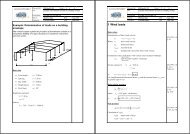
Autogenous shrinkageStichtse Bridge, 1997:Autogenous shrinkage20.10 -3 after 2 dayslConcrete strength f c =90 MPa22 February 2008 18
Shrinkage (3.1.4)βds( t,ts)=( t− ts( t − ts)) + 0,04h30where t = age <strong>of</strong> <strong>concrete</strong> at time considered, t s= age at beginning <strong>of</strong>drying shrinkage (mostly end <strong>of</strong> curing)εca( t)β ( t)ε ( ∞)where=as ca−60,5εca( ∞)= 2,5( fck−10)⋅10and β ( t)= 1−exp( −0,2t)as22 February 2008 19
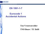
Creep <strong>of</strong> <strong>concrete</strong> (3.1.4)123t 0SNInside conditions – RH = 50%Example: 600 mm thick slab, loading at 30 days, C30/37 - ϕ = 1,8R5102030C20/25C25/30C30/37C35/45C40/50C45/55C50/60 C55/67C60/75 C70/85C80/95C90/105501007,06,0ϕ (∞, t 0)5,04,03,0 2,0 1,0 0 100 300 500 700 900 1100 1300 1500h 0 (mm)h 0= 2A c/u where A cis the cross-section area andu is perimeter <strong>of</strong> the member in contact with the atmosphere22 February 2008 20
Confined Concrete (3.1.9)σ1 = fck,cσcfck,cfckfcd,cσ2 σ3 ( = σ2)A0εcuεc2,cεcu2,cεcf ck,c= f ck(1.000 + 5.0 σ 2/f ck)for σ 2≤ 0.05f ck= f ck(1.125 + 2.50 σ 2/f ck) for σ 2> 0.05f ckε c2,c= ε c2(f ck,c/f ck)2ε cu2,c= ε cu2+ 0,2 σ 2/f ck22 February 2008 21
Stress-strain relations for reinforcing steel22 February 2008 22
Reinforcement (2) – From Annex CProduct form Bars and de-coiled rods Wire FabricsClass A B C A B CCharacteristic yieldstrength f yk or f 0,2k (MPa)cold worked400 to 600hot rolledseismick = (f t /f y ) k ≥1,05 ≥1,08 ≥1,15
Idealized and design stress strain relations for reinforcing steelAlternative design stress/strain relationships are permitted:- inclined top branch with a limit to the ultimate strain horizontal- horizontal top branch with no strain limitσIdealisedkfykfykkfyk/γsfyd = fyk/γs<strong>Design</strong>k = (f t /f y ) kfyd/ Esε udε ukεε ud = 0.9 ε uk22 February 2008 24
Durability and coverPr<strong>of</strong>.dr.ir. J.C. Walraven22 February 200825Group Concrete Structures
Penetration <strong>of</strong> corrosion stimulatingcomponents in <strong>concrete</strong>22 February 2008 26
Deterioration <strong>of</strong> <strong>concrete</strong>Corrosion <strong>of</strong> reinforcement by chloride penetration22 February 2008 27
Deterioration <strong>of</strong> <strong>concrete</strong> <strong>structures</strong>Corrosion <strong>of</strong> reinforcement by chloride attack in amarine environment22 February 2008 28
Avoiding corrosion <strong>of</strong> steel in <strong>concrete</strong><strong>Design</strong> criteria- Aggressivity <strong>of</strong> environment- Specified service life<strong>Design</strong> measures- Sufficient cover thickness- Sufficiently low permeability <strong>of</strong> <strong>concrete</strong> (in combination with coverthickness)- Avoiding harmfull cracks parallel to reinforcing bars- Other measures like: stainless steel, cathodic protection, coatings, etc.22 February 2008 29
Aggressivity <strong>of</strong> the environmentMain exposure classes:• The exposure classes are defined in EN206-1. The main classes are:• XO – no risk <strong>of</strong> corrosion or attack• XC – risk <strong>of</strong> carbonation induced corrosion• XD – risk <strong>of</strong> chloride-induced corrosion (other than sea water)• XS – risk <strong>of</strong> chloride induced corrosion (sea water)• XF – risk <strong>of</strong> freeze thaw attack• XA – Chemical attack22 February 2008 30
Cover to reinforcement, required to fulfillservice life demandsDefinition <strong>of</strong> <strong>concrete</strong> coverOn drawings the nominal cover should be specified. It isdefined as a minimum cover c min plus an allowance in designfor deviation Δc dev, soc nom = c min +Δc dev22 February 2008 32
Procedure to determine c min,durEC-2 leaves the choice <strong>of</strong> c min,dur to the countries, but gives thefollowing recommendation:The value c min,dur depends on the “structural class”, which has to bedetermined first. If the specified service life is 50 years, the structuralclass is defined as 4. The “structural class” can be modified in case <strong>of</strong>the following conditions:-The service life is 100 years in stead <strong>of</strong> 50 years-The <strong>concrete</strong> strength is higher than necessary- Slabs (position <strong>of</strong> reinforcement not affected by construction process- Special quality control measures applyThe finally applying service class can be calculated with Table 4.3N22 February 2008 34
Table for determining final Structural Class22 February 2008 35
Final determination <strong>of</strong> c min,dur (1)The value c min,dur is finally determined as a function <strong>of</strong> the structuralclass and the exposure class:22 February 2008 36
Special considerationsIn case <strong>of</strong> stainless steel the minimum cover may be reduced.The value <strong>of</strong> the reduction is left to the decision <strong>of</strong> the countries(0 if no further specification).22 February 2008 37
Structural Analysis22 February 2008 38
Methods to analyse <strong>structures</strong>Linear elastic analysis1. Suitable for ULS and SLS2. Assumptions:- uncracked cross-sections- linear σ - ε relations-meanE-modulus3. Effect <strong>of</strong> imposed deformationsin ULS to be calculated withreduced stiffnesses and creep22 February 2008 39
Geometric Imperfections (5.2)• Deviations in cross-sectiondimensions are normally taken intoaccount in the material factors andshould not be included in structuralanalysisθ iHiNbNal• Imperfections need not beconsidered for SLS• Out-<strong>of</strong>-plumb is represented by an inclination, θ lθ l = θ 0 α h α m where θ 0 = l/200α h = 2/√l; 2/3 ≤ α h ≤ 1α m = √(0,5(1+1/m)l is the height <strong>of</strong> member (m)m is the number <strong>of</strong> vert. members22 February 2008 40
Forces due to geometric imperfections on<strong>structures</strong>(5.2)θ iHiNaNblθi/2θ iHiNaθi/2NbBracing System Floor Diaphragm Ro<strong>of</strong>H i = θ i (N b -N a )H i = θ i (N b +N a )/2H i = θ i N a22 February 2008 41
Methods to analyse <strong>structures</strong>5.5 Linear elastic analysis with limited redistribution1. Valid for 0,5 ≤ l 1 / l 2 ≤ 2,02. Ratio <strong>of</strong> redistribution δ, withδ ≥ k 1 + k 2 x u /d for f ck ≤ 50 MPaδ ≥ k 3 + k 4 x u /d for f ck > 50 MPaM 2M 1δ ≥ k 5 for reinforcement class B or Cδ ≥ k 6 for reinforcement class Al 1 l 222 February 2008 42
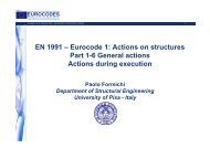
Redistribution limits for Class B & C steel353025% redist201510500.25 0.30 0.35 0.40 0.45 0.50 0.55 0.60x /dfck =70 fck =60 fck =5022 February 2008 43
Methods to analyse <strong>structures</strong>5.6 Plastic methods <strong>of</strong> analysis(a) Yield line analysis(b) Strut and tie analysis(lower bound)- Suitable for ULS- Suitable for SLS if compatibilityis ensured (direction <strong>of</strong> strutsoriented to compression in elasticanalysis22 February 2008 44
Methods to analyse <strong>structures</strong>Ch. 5.7 Nonlinear analysis“Nonlinear analysis may be usedfor both ULS and SLS, providedthat equilibrium and compatibilityare satisfied and an adequate nonlinearbehaviour for materials isassumed. The analysis may be firstor second order”.22 February 2008 45
Chapter 5 “Structural analysis”5.8 Second order effects with axial loads- Slenderness criteria for isolated membersand buildings (when is 2 nd order analysis required?)- Methods <strong>of</strong> second order analysis• General method based on nonlinearbehaviour, including geometric nonlinearity• Analysis based on nominal stiffness• Analysis based on moment magnification factor• Analysis based on nominal curvatureExtended calculation tools are given22 February 2008 46
Methods <strong>of</strong> analysisBiaxial bendingM Rdz/yM Rdz/ydesign moment aroundrespective axismoment resistance inrespective directionFor circular and elliptical cross-sectiona = 2.For rectangular cross section, see tableN E /N Rd 0,1 0,7 1,0a 1,0 1,5 2,022 February 2008 47
Methods <strong>of</strong> analysisLateral buckling <strong>of</strong> beamsNo lateral buckling if:22 February 2008 48
Bending with or without axial forcePr<strong>of</strong>.dr.ir. J.C. Walraven22 February 200849Group Concrete Structures
Concrete design stress - strain relations (3.1.5 and 3.1.7)for section analysisσcfck“Parabola-rectangle”σcfck“Bi-linear”fcdfcd0ε c2n⎡ ⎛ ε ⎞ ⎤cσ = f ⎢1 − ⎜1 − ⎟ ⎥ for 0 ≤ ε < ε⎢εc2⎣ ⎝ ⎠ ⎥⎦σ = f for ε ≤ ε ≤ εc cd c c2c cd c2 c cu2n = 1,4 + 23,4 [(90- f ck)/100] 4for f ck≥ 50 MPa otherwise 2,0ε cu2ε c2 (0 / 00) = 2,0 + 0,085(f ck-50) 0,53for f ck≥ 50 MPa otherwise 2,0ε cu2( 0 / 00) = 2,6 + 35 [(90-f ck)/100] 4for f ck≥ 50 MPa otherwise 3,5ε c0εc3ε cu3ε c3( 0 / 00) = 1,75 + 0,55 [(f ck-50)/40]for f ck≥ 50 MPa otherwise 1,75ε cu3( 0 / 00) =2,6+35[(90-f ck)/100] 4for f ck≥ 50 MPa otherwise 3,5ε c22 February 2008 50
Concrete design stress strain relations fordifferent strength classes- Higher <strong>concrete</strong> strength shows more brittle behaviour,reflected by shorter horizontal branche22 February 2008 51
Simplified <strong>concrete</strong> design stress blockεcu3η fcdAcxλxFcdAsFsεsλ = 0,8= 0,8 −for f ck≤ 50 MPa(fck −40050)for 50 < f ck≤ 90 MPaη = 1,0for f ck≤ 50 MPa= 1,0 – (f ck– 50)/200 for 50 < f ck≤ 90 MPa22 February 2008 52
Simplified factors for flexure (1)Factors for NA depth (n) and lever arm (=z) for <strong>concrete</strong> grade ≤ 50 MPa1.201.00lever arm0.80Factor0.600.40NA depth0.200.000.01 0.02 0.03 0.04 0.05 0.06 0.07 0.08 0.09 0.10 0.11 0.12 0.13 0.14 0.15 0.16 0.17n 0.02 0.04 0.07 0.09 0.12 0.14 0.17 0.19 0.22 0.24 0.27 0.30 0.33 0.36 0.39 0.43 0.46z 0.99 0.98 0.97 0.96 0.95 0.94 0.93 0.92 0.91 0.90 0.89 0.88 0.87 0.86 0.84 0.83 0.82M/bd 2 f ck22 February 2008 53
Simplified factors for flexure (2)Factors for NA depth (=n) and lever arm (=z) for <strong>concrete</strong> grade 70 MPa1.201.00lever arm0.80Factor0.600.40NA depth0.200.000.01 0.02 0.03 0.04 0.05 0.06 0.07 0.08 0.09 0.10 0.11 0.12 0.13 0.14 0.15 0.16 0.17n 0.03 0.05 0.08 0.11 0.14 0.17 0.20 0.23 0.26 0.29 0.33z 0.99 0.98 0.97 0.96 0.95 0.94 0.93 0.91 0.90 0.89 0.88M/bd 2 f ck22 February 2008 54
Column design chart for f ck ≤ 50 MPa21.8bd 1Nd/bhfcd1.61.41.210.80.600.10.20.3A sf yk/bhf ck1.00.8 0.90.6 0.70.4 0.5d 1d 1 /h = 0.05f ck
Column design chart for f ck = 70 MPa21.8d 1bNd/bhfcd1.61.41.210.80.60.40.200.10.20.3A sf yk/bhf ck1.00.8 0.90.6 0.70.4 0.5d 1d 1 /h = 0.1f ck = 90h00 0.05 0.1 0.15 0.2 0.25 0.3 0.35 0.4 0.45 0.5 0.55 0.6M d /bh 2 f cd22 February 2008 56
ShearPr<strong>of</strong>.dr.ir. J.C. Walraven22 February 200857Group Concrete Structures
Principles <strong>of</strong> shear control in EC-2Until a certain shear force V Rd,c no calculated shear reinforcementis necessary (only in beams minimum shear reinforcement isprescribed)If the design shear force is larger than this value V Rd,c shearreinforcement is necessary for the full design shear force. Thisshear reinforcement is calculated with the variable inclination trussanalogy. To this aim the strut inclination may be chosen betweentwo values (recommended range 1≤ cot θ ≤ 2,5)The shear reinforcement may not exceed a defined maximumvalue to ensure yielding <strong>of</strong> the shear reinforcement22 February 2008 58
Concrete slabs without shearreinforcementShear resistance V Rd,c governed by shear flexurefailure: shear crack develops from flexural crack22 February 2008 59
Concrete slabs without shearreinforcementPrestressed hollow core slabShear resistance V Rd,c governed by shear tension failure:crack occurs in web in region uncracked in flexure22 February 2008 60
Concrete beam reinforced in shearShear failure introduced by yielding <strong>of</strong> stirrups,followed by strut rotation until web crushing22 February 2008 61
Principle <strong>of</strong> variabletruss actionApproach “Variable inclination struts”:a realisticStage 1: web uncracked in shearStage 2: inclined cracks occurStage 3: stabilized inclined cracksStage 4: yielding <strong>of</strong> stirrups,further rotation, finallyweb crushingStrut rotation as measured in tests(TU Delft)22 February 2008 62
Principles <strong>of</strong> variable angle trussStrut rotation, followed by new cracks under lower angle, even inhigh strength <strong>concrete</strong> (Tests TU Delft)22 February 2008 63
Web crushing in <strong>concrete</strong> beamWeb crushing providesmaximum to shear resistanceAt web crushing:V Rd,max = b w z υ f cd /(cotθ + tanθ)22 February 2008 64
Advantage <strong>of</strong> variable angle truss analogy-Freedom <strong>of</strong> design:• low angle θ leads to low shear reinforcement• High angle θ leads to thin webs, saving <strong>concrete</strong>and dead weightOptimum choice depends on type <strong>of</strong> structure- Transparent equilibrium model, easy in use22 February 2008 65
Shear design value under which no shearreinforcement is necessary in elementsunreinforced in shear (general limit)VRd, c= CRd, ck( 100ρlfck)1/3bwdC Rd,c coefficient derived from tests (recommended 0,12)k size factor = 1 + √(200/d) with d in meterρ l longitudinal reinforcement ratio ( ≤0,02)f ck characteristic <strong>concrete</strong> compressive strengthb w smallest web widthd effective height <strong>of</strong> cross section22 February 2008 66
Shear design value under which no shearreinforcement is necessary in elementsunreinforced in shear (general limit)Minimum value for V Rd,c:V Rd,c = v min b w dValues for v min (N/mm 2 )d=200 d=400 d=600 d=800C20 0,44 0,35 0,25 0,29C40 0,63 0,49 0,44 0,41C60 0,77 0,61 0,54 0,50C80 0,89 0,70 0,62 0,5822 February 2008 67
Shear design value under which no shearreinforcement is necessary in elementsunreinforced in shear (special case <strong>of</strong> sheartension)22 February 2008 68
Special case <strong>of</strong> shear tension (examplehollow core slabs)VIb wSf ctdα lσ cpI⋅b=w( f )2Rd , cctdS+αmoment <strong>of</strong> inertiasmallest web widthsection modulusdesign tensile strength <strong>of</strong> <strong>concrete</strong>reduction factor for prestress in case <strong>of</strong>prestressing strands or wires in ends <strong>of</strong> member<strong>concrete</strong> compressive stress at centroidal axis iforfor fully developed prestress22 February 2008 69lσcpfctd
sσc=zθθ Afswyw= fVzcot θVu,3u,2<strong>Design</strong> <strong>of</strong> members if shearreinforcement is needed (V E,d >V Rd,c )V u,3θsAz cot θfsw ywzσ c = f c1V u,2θ= fυ cFor most cases:-Assume cot θ = 2,5 (θ = 21,8 0 )-Calculate necessary shear reinforcement-Check if web crushing capacity is not exceeded (V Ed >V Rd,s )-If web crushing capacity is exceeded, enlarge web width or calculatethe value <strong>of</strong> cot θ for which V Ed = V Rd,c and repeat the calculation22 February 2008 70
sσc=zθθ Afswyw= fVzcot θVu,3u,2Upper limit <strong>of</strong> shear capacity reached dueto web crushingV u,3θsAz cot θfsw ywzσ c = f c1V u,2θ= fυ cFor yielding shear reinforcement:V Rd,s = (A sw /s) z f ywd cotθθ from 45 0 to 21,8 02,5 times larger capacityAt web crushing:V Rd,max = b w z υ f cd /(cotθ + tanθ)θ from 21,8 0 to 45 01,45 times larger capacity22 February 2008 71
Special case <strong>of</strong> loads near to supportsdda va vFor a v ≤ 2d the contribution <strong>of</strong> the point load to the shear force V Ed may bereduced by a factor a v /2d where 0.5 ≤ a v ≤ 2d provided that the longitudinalreinforcement is fully anchored at the support. However, the conditionV Ed ≤ 0,5b w dυf cdshould always be fulfilled22 February 2008 72
Influence <strong>of</strong> prestressing on shearresistance (1)1. Prestressing introduces a set <strong>of</strong> loads on the beam22 February 2008 73
Influence <strong>of</strong> prestressing on shearresistance (2)Prestressing increases the load V Rc,dbelow which no calculatedshear reinforcement is required1/3VRd , c= [ CRd, ck(100ρ lfck) + k1σcp] bwdk 1 coefficient, with recommended value 0,15σ cp <strong>concrete</strong> compressive stress at centroidal axis dueto axial loading or prestressing22 February 2008 74
Influence <strong>of</strong> prestressing on shearresistance (3)1. Prestressing increases the web crushing capacityVRd, max= αcwbwzνfcd/(cotθ+ tanθ)α cw factor depending on prestressing forceα cw= 1 for non prestressed <strong>structures</strong>(1+σ cp/f cd) for 0,25 < σ cp < 0,25f cd1,25 for 0,25f cd
Increase <strong>of</strong> web crushing capacity byprestressing (4)22 February 2008 76
Influence <strong>of</strong> prestressing on shearresistance (4)Reducing effect <strong>of</strong> prestressing duct (with or without tendon)on web crushing capacityGrouted ductsb w,nom = b w - ΣφUngrouted ducts b w,nom = b w –1,2 Σφ22 February 2008 77
Shear between web and flanges <strong>of</strong> T-sectionsStrut angle θ:1,0 ≤ cot θ f ≤ 2,0 for compression flanges (45 0 ≥θ f ≥ 26,5 01,0 ≤ cot θ f ≤ 1,25 for tension flanges (45 0 ≥θ f ≥ 38,6 0 )No transverse tension ties required if shear stress in interfacev Ed = ΔF d /(h f·Δx) ≤ kf ctd (recommended k = 0,4)22 February 2008 78
Shear at the interface between <strong>concrete</strong>scast at different timesInterface shear models based on shear friction principle22 February 2008 79
Shear at the interface between <strong>concrete</strong>scast at different times22 February 2008 80
Shear at the interface between <strong>concrete</strong>’scast at different times (<strong>Eurocode</strong> 2, Clause6.5.2)v Rdi = c⋅f ctd + μ⋅σ n + ρ⋅f yd (μ⋅sin β + cos β) ≤ 0,5 ν⋅f cdf ctd=<strong>concrete</strong> design tensile strengthσ n = eventual confining stress, notfrom reinforcementρ= reinforcement ratioβ = inclination between reinforcementand <strong>concrete</strong> surfacef cd= <strong>concrete</strong> design compressivestrengthυ = 0,6 for f ck≤ 60 MPa= 0,9 – f ck/200≥0,5 for f ck≥ 60 MPaVery smoothcsmooth 0,35rough 0,45indented 0,50μ0,25 0,5(=tan α)0,60,70,822 February 2008 81
TorsionPr<strong>of</strong>.dr.ir. J.C. Walraven22 February 200882Group Concrete Structures
Modeling solid cross sections byequivalent thin-walled cross sectionsCentre-lineziCoverTEdOuter edge <strong>of</strong> effectivecrossection, circumference utef/2tefEffective wall-thickness follows from t ef,i =A/u, where;A = total area <strong>of</strong> cross section within outer circumference, including hollow areasU = outer circumference <strong>of</strong> the cross section22 February 2008 83
<strong>Design</strong> procedure for torsion (1)Shear flow in any wall followsfrom:τt, itef, i=whereTEd2Akτ t,It ef,IT EdA ktorsional shear stress in wall Ieffective wall thickness (A/u)applied torsional momentarea enclosed by centre lines<strong>of</strong> connecting walls, includinghollow areas22 February 2008 84
<strong>Design</strong> procedure for torsion (2)Shear force V Ed in wall i due totorsion is:VEd , i= τt,itef, iziwhereτ t,It ef,IZ itorsional shear stress in wall ieffective wall thickness (A/u)inside length <strong>of</strong> wall I definedby distance <strong>of</strong> intersectionpoints with adjacent walls22 February 2008 85
<strong>Design</strong> procedure for torsion (3)The shear reinforcement in any wall can now be designed like a beamusing the variable angle truss analogy, with 1≤ cot θ ≤ 2,522 February 2008 86
<strong>Design</strong> procedure for torsion (4)The longitudinal reinforcement in any wall follows from:ΣAslukfyd=TEdA2 kcotθwhereu kf ykθperimeter <strong>of</strong> area A kdesign yield stress <strong>of</strong> steelangle <strong>of</strong> compression struts22 February 2008 87
Punching shearPr<strong>of</strong>.dr.ir. J.C. Walraven22 February 200888Group Concrete Structures
<strong>Design</strong> for punching shearMost important aspects:- Control perimeter- Edge and corner columns- Simplified versus advancedcontrol methods22 February 2008 89
Definition <strong>of</strong> control perimeter22 February 2008 90
Definition <strong>of</strong> control perimetersThe basic control perimeter u 1 is taken at a distance 2,0d fromthe loaded area and should be constructed as to minimise its length22 February 2008 91
Limit values for design punchingshear stress in designThe following limit values for the punching shear stress are used indesign:IfvEd≤ v Rd , cno punching shear reinforcement requiredwhere:v1/3Rd , c= CRd, ck( 100ρ lfck) + 0,10σcp≥ ( vmin+ 0,10σcp)22 February 2008 92
How to take account <strong>of</strong> eccentricityMore sophisticated method for internal columns:zc12dyc22de y and e zb y and b zeccentricities M Ed /V Ed along y and z axesdimensions <strong>of</strong> control perimeter22 February 2008 93
How to take account <strong>of</strong> eccentricityVOr, how to determine β in equationEdvEd= βu dCiβ = 1,5B Aβ = 1,4β = 1,15For <strong>structures</strong> where lateralstability does not depend onframe action and whereadjacent spans do not differby more than 25% theapproximate values for βshown below may be used:22 February 2008 94
How to take account <strong>of</strong> eccentricityAlternative for edge and corner columns: use perimeter u 1* in stead <strong>of</strong>full perimeter and assume uniform distribution <strong>of</strong> punching force22 February 2008 95
<strong>Design</strong> <strong>of</strong> punching shear reinforcementIf v Ed ≥ v Rd,c shear reinforcementis required.The steel contribution comesfrom the shear reinforcementcrossing a surface at 1,5d fromthe edge <strong>of</strong> the loaded area, toensure some anchorage at theupper end. The <strong>concrete</strong>component <strong>of</strong> resistance istaken 75% <strong>of</strong> the designstrength <strong>of</strong> a slab without shearreinforcement22 February 2008 96
Punching shear reinforcementCapacity with punching shear reinforcementV u = 0,75V Rd,c + V SShear reinforcement within 1,5d from column is accounted for withf y,red = 250 + 0,25d(mm)≤f ywd22 February 2008 97
Punching shear reinforcementOuter controlperimeterAkdOuter perimeter <strong>of</strong> shearreinforcement0.5d0.75d1.5d (2d if > 2d fromcolumn)AThe outer control perimeter at whichshear reinforcement is not required,should be calculated from:u out,ef= V Ed/ (v Rd,cd)0.5d0.75dOuter controlperimeterkdThe outermost perimeter <strong>of</strong> shearreinforcement should be placed at adistance not greater than kd (k =1.5) within the outer controlperimeter.Section A - A22 February 2008 98
Special types <strong>of</strong> punching shear reinforcementDowel strips22 February 2008 99
Punching shear reinforcementWhere proprietary systems are used the control perimeter at which shearreinforcement is not required, u outor u out,ef(see Figure) should be calculated fromthe following expression:u out,ef= V Ed/ (v Rd,cd)uout,efuout> 2d2d1,5d1,5dd22 February 2008 100d
Punching shear• Column bases; critical parameters possible at a
<strong>Design</strong> with strut and tie modelsPr<strong>of</strong>.dr.ir. J.C. Walraven22 February 2008102Group Concrete Structures
General idea behind strut and tie modelsStructures can be subdivided into regions with a steady state <strong>of</strong>the stresses (B-regions, where “B” stands for “Bernoulii” and inregions with a nonlinear flow <strong>of</strong> stresses (D-regions, where “D”stands for “Discontinuity”22 February 2008 103
D-region: stress trajectories and strut andtie modelSteps in design:1. Define geometry <strong>of</strong> D-region(Length <strong>of</strong> D-region is equalto maximum width <strong>of</strong> spread)2. Sketch stress trajectories3. Orient struts to compressiontrajectories4. Find equilibrium model byadding tensile ties5. Calculate tie forces6. Calculate cross section <strong>of</strong> tie7. Detail reinforcement22 February 2008 104
Examples <strong>of</strong> D-regions in <strong>structures</strong>22 February 2008 105
<strong>Design</strong> <strong>of</strong> struts, ties and nodesStruts with transverse compression stress or zero stress:σ Rd,max = f cd22 February 2008 106
<strong>Design</strong> <strong>of</strong> struts, ties and nodesStruts in cracked compression zones, with transverse tensionσ Rd,max = υf cdRecommended value υ = 0,60 (1 – f ck /250)22 February 2008 107
<strong>Design</strong> <strong>of</strong> struts, ties and nodesCompression nodes without tieσ Rd,max = k 1 υ’ f cdwhereυ’ = 0,60 (1 – f ck /250)Recommended valueK 1 = 1,022 February 2008 108
<strong>Design</strong> <strong>of</strong> struts, ties and nodesCompression-Compression-Tension (CTT) nodeσ Rd,max = k 2 υ’ f cdwhereυ’ = 0,60 (1 – f ck /250)Recommended valuek 2 = 0,8522 February 2008 109
<strong>Design</strong> <strong>of</strong> struts, ties and nodesCompression-Tension-Tension (CTT) nodeσ Rd,max = k 3 υ’ f cdwhereυ’ = 0,60 (1 – f ck /250)Recommended valuek 3 = 0,7522 February 2008 110
Example <strong>of</strong> detailing based on strut and tiesolutionStress - strain relation for confined <strong>concrete</strong> (dotted line)22 February 2008 111
Bearing capacity <strong>of</strong> partially loaded areas22 February 2008 112
Crack width control in <strong>concrete</strong> <strong>structures</strong>Pr<strong>of</strong>.dr.ir. J.C. Walraven22 February 2008113Group Concrete Structures
Theory <strong>of</strong> crack width control (4)NWhen more cracks occur, more disturbed regions are found in the<strong>concrete</strong> tensile bar. In the N-ε relation this stage (the “crackformation stage” is characterized by a “zig-zag”-line (N r,1 -N r,2 ). At acertain strain <strong>of</strong> the bar, the disturbed areas start to overlap.If no intermediate areas are left, the <strong>concrete</strong> cannot reach thetensile strength anymore, so that no new cracks can occur. The“crack formation stage” is ended and the stabilized cracking stagestarts. No new cracks occur, but existing cracks widen. t2 . t 2. t 2. t tNNN rN r,1N r,2N 0disturbed area22 February 2008 114ε
EC-formulae for crack width control (1)For the calculation <strong>of</strong> the maximum (or characteristic) crack width,the difference between steel and <strong>concrete</strong> deformation has to becalculated for the largest crack distance, which is s r,max = 2l t . Sowk=sr,max( )ε − εsmcmEq. (7.8) tσ srσ sesteel stress tf ctmwwheres r,max is the maximum crack distanceand(ε sm - ε cm ) is the difference in deformation betweensteel and <strong>concrete</strong> over the maximum crack distance.Accurate formulations for s r,max and (ε sm -ε cm ) will be given<strong>concrete</strong> stress22 February 2008 115
EC-2 formulae for crack width control(2)fct,effσs− kt( 1+αeρp,eff)ρp,effσsεsm− εcm=≥ 0, 6EEssEq. 7.0where: σ s is the stress in the steel assuming a cracked sectionα eis the ratio E s /E cmρ p,eff = (A s + ξA p )/A c,eff(effective reinforcement ratioξk tincluding eventual prestressing steel A pis bond factor for prestressing strands or wiresis a factor depending on the duration <strong>of</strong> loading(0,6 for short and 0,4 for long term loading)22 February 2008 116
EC-3 formulae for crack width control (4)Maximum final crack spacing s r,maxsr, max 3.4c+ 0. 425 k1k2ρ φ= (Eq. 7.11)p,effwhere c is the <strong>concrete</strong> coverΦ is the bar diameterk 1 bond factor (0,8 for high bond bars, 1,6 for barswith an effectively plain surface (e.g.prestressing tendons)k 2 strain distribution coefficient (1,0 for tensionand 0,5 for bending: intermediate values van beused)22 February 2008 117
EC-2 requirements for crack width control(recommended values)Exposure classRC or unbondedPSC membersQuasi-permanentloadPrestressedmembers withbonded tendonsFrequent loadX0,XC1 0.3XC2,XC3,XC4XD1,XD2,XS1,XS2,XS30.30.2Decompression22 February 2008 118
EC-2 formulae for crack width control (5)In order to be able to applythe crack width formulae,basically valid for a <strong>concrete</strong>tensile bar, to a structureloaded in bending, adefinition <strong>of</strong> the “effectivetensile bar height” isnecessary. The effectiveheight h c,ef is the minimum<strong>of</strong>:2,5 (h-d)(h-x)/3h/2ab2.5 (h-d) < h-x e3beamceff. crosssectionslabdgravity line<strong>of</strong> steelφhcelement loadedin tensiontcsmallest value <strong>of</strong>φ2.5 . (c + /2) <strong>of</strong> t/2smallest value <strong>of</strong>φ2.5 . (c + /2)<strong>of</strong>(h - x e)/322 February 2008 119
Maximum bar diameters for crackcontrol (simplified approach 7.3.3)50maximum bar diameter (mm)40302010w k = 0.4w k =0.3 mmw k =0.2 mm0100 150 200 250 300 350 400 450 500Reinforcement stress, σ s (N/mm 2 )22 February 2008 120
Maximum bar spacing for crack control(simplified approach 7.3.3)300Maximum bar spacing (mm)25020015010050w k = 0.2w k = 0.4w k = 0.30150 200 250 300 350 400stress in reinforcement (MPa)22 February 2008 121
Example (1)Continuous <strong>concrete</strong> roadData: Concrete C20/25, f ctm = 2,2 MPa, shrinkage ε sh =0,25·10 -3 ,temperature difference in relation to construction situation ΔT=25 0 .Max. crack width allowed = 0,2mm.CalculationThe maximum imposed deformation (shrinkage + temperature) isε tot = 0,50·10 -3 . Loading is slow, so E c,∞ =E c /(1+ϕ) ≅ 30.000/(1+2) =10.000 MPa. At ε tot = 0,50 ·10 -3 a <strong>concrete</strong> tensile strength <strong>of</strong> 5MPa applies, so the road is cracked.Cont. →22 February 2008 122
Example (1, cont.)For imposed deformation the “crackformation stage” applies. So, the load willnot exceed the cracking load, which is N cr= A c(1+nρ)f ctm≅ 1,1A cf ctm= 330 kN for b =1m. From the diagram at the right it isfound that a diameter <strong>of</strong> 12mm wouldrequire a steel stress not larger than 225MPa. To meet this requirement d =12mmbars at distances 150mm, both at top andbottom, are required.maximum bar diameter (mm)50w k = 0.44030w k =0.3 mm20w k =0.2 mm100100 150 200 250 300 350 400 450 500Reinforcement stress, σ s (N/mm 2 )22 February 2008 123
Example (2)q=4kN/mm2q6000275φ12-17515A slab bearing into one direction is subjected to a maximumvariable load <strong>of</strong> 4KN/m 2 . It should be demonstrated that themaximum crack width under the quasi permanent loadcombination is not larger than 0,4mm. (The floor is a part <strong>of</strong> ashopping centre: the environmental class is X0) (cont.→)22 February 2008 124
Example (2)q=4kN/mm2q6000275φ12-17515The governing load for the quasi-permanent load combination is:q = q g + ψ 2·q var. = (0.275·2500) + 0,6·400 = 928 kg/m 2 . Themaximum bending moment is then M = 9,28·6 2 /8=41,8 kNm/m ’ .For this bending moment the stress in the steel is calculated asσ s =289 MPa.Cont.→22 February 2008 125
Example (2)77.3hiddentieφ12The effective height <strong>of</strong> the tensile tie is the minimum <strong>of</strong> 2,5(c+ φ/2) <strong>of</strong> (hx)/3,where x = height <strong>of</strong> compression zone, calculated as 44mm. So, thegoverning value is (h-x)/3 = 77 mm. The effective reinforcement ratio isthen ρ eff= (113/0,175)/(77·1000)=0,83·10 -2. The crack distance s r,amx(Eq. 7.11) is found to be 245mm. For the term (ε sm-ε cm) a value 1,0·10 -3is found. This leads to a cracks width equal to w k= 0,25 mm, which hissmaller than the required 0,4mm.22 February 2008 126
Example (2)q=4kN/mm2q6000275φ12-17515A slab bearing into one direction is subjected to a maximumvariable load <strong>of</strong> 4KN/m 2 . It should be demonstrated that themaximum crack width under the quasi permanent loadcombination is not larger than 0,4mm. (The floor is a part <strong>of</strong> ashopping centre: the environmental class is X0) (cont.→)22 February 2008 127
Deformation <strong>of</strong> <strong>concrete</strong> <strong>structures</strong>Pr<strong>of</strong>.dr.ir. J.C. Walraven22 February 2008128Group Concrete Structures
Deformation <strong>of</strong> <strong>concrete</strong>Reason to worry orchallenge for the future?Deflection <strong>of</strong> ECC specimen, V. Li, University<strong>of</strong> MichiganDamage in masonry wall due to excessivedeflection <strong>of</strong> lintel22 February 2008 129
Reasons for controling deflections (1)AppearanceDeflections <strong>of</strong> such amagnitude that membersappear visibly to sag willupset the owners oroccupiers <strong>of</strong> <strong>structures</strong>. It isgenerally accepted that adeflection larger thanspan/250 should be avoidedfrom the appearance point<strong>of</strong> view. A survey <strong>of</strong><strong>structures</strong> in Germany thathad given rise to complaintsproduced 50 examples. Themeasured sag was less thanspan/250 in only two <strong>of</strong> these.22 February 2008 130
Reasons for controling deflections (2)Damage to non-structuralMembersAn important consequence <strong>of</strong> excessivedeformation is damage to nonstructural members, like partition walls.Since partition walls are unreinforcedand brittle, cracks can be large (severalmillimeters). The most commonlyspecified limit deflection is span/500,for deflection occurring afterconstruction <strong>of</strong> the partitions. It shouldbe assumed that all quasi permanentloading starts at the same time.22 February 2008 131
Reasons for controling deflections (3)CollapseIn recent years many cases <strong>of</strong>collapse <strong>of</strong> flat ro<strong>of</strong>s havebeen noted. If the rainwaterpipes have a too low capacity,<strong>of</strong>ten caused by pollution andfinally stoppage, the ro<strong>of</strong>deflects more and more underthe weight <strong>of</strong> the water andfinally collapses. This occurspredominantly with light ro<strong>of</strong>s.Concrete ro<strong>of</strong>s are lesssusceptible for this type <strong>of</strong>damage22 February 2008 132
EC-2 Control <strong>of</strong> deflectionsDeflection limits according tochapter 7.4.1• Under the quasi permanent loadthe deflection should not exceedspan/250, in order to avoidimpairment <strong>of</strong> appearance andgeneral utility• Under the quasi permanentloads the deflection should belimited to span/500 afterconstruction to avoid damage toadjacent parts <strong>of</strong> the structure22 February 2008 133
EC-2: SLS - Control <strong>of</strong> deflectionsControl <strong>of</strong> deflection can bedone in two ways- By calculation- By tabulated values22 February 2008 134
Calculating the deflection <strong>of</strong> a <strong>concrete</strong> memberThe deflection follows from:δ = ζ δ II + (1 - ζ)δ Iδδ Iδ IIζdeflectiondeflection fully crackeddeflection uncrackedcoefficient for tension stiffening (transition coefficient)ζ = 1 - β (σ sr /σ s ) 2σ srσ sβsteel stress at first crackingsteel stress at quasi permanent service load1,0 for single short-term loading0,5 for sustained loads or repeated loading22 February 2008 135
Calculating the deflection <strong>of</strong> a <strong>concrete</strong>memberThe transition from the uncracked state (I) to the cracked state (II) does notoccur abruptly, but gradually. From the appearance <strong>of</strong> the first crack,realistically, a parabolic curve can be followed which approaches the line forthe cracked state (II).22 February 2008 136
Calculating the deflection <strong>of</strong> a <strong>concrete</strong> memberFor pure bending the transitionfactorξ = 1− β ( σ s/ σrcan as well be written as2)ξ = 1− β ( / MM cr2)where M cris the cracking moment and M is the applied moment22 February 2008 137
Calculating the deflection <strong>of</strong> a <strong>concrete</strong> member7.4.3 (7)“The most rigorous method <strong>of</strong> assessingdeflections using the method givenbefore is to compute the curvatures atfrequent locations along the memberand then calculate the deflection bynumerical integration.In most cases it will be acceptableto compute the deflection twice,assuming the whole member to be inthe uncracked and fully cracked conditionin turn, and then interpolate using theexpression:ξ = 1− β ( / MM cr2)22 February 2008 138
Cases where detailed calculation may beomittedIn order to simplify the design,expressions have been derived, givinglimits <strong>of</strong> l/d for which no detailedcalculation <strong>of</strong> the deflection has to becarried out.These expressions are the results <strong>of</strong> anextended parameter analysis with themethod <strong>of</strong> deflection calculation asgiven before. The slenderness limitshave been determined with the criteriaδ
Calculating the deflection <strong>of</strong> a <strong>concrete</strong> memberFor span-depth ratios below the following limits no further checks is neededl3⎡2 ⎤⎢ρ0⎛ ρ0⎞= K 11 + 1,5 f + ⎜ − ⎟ ⎥ck3,2 fck1 if ρ ≤ ρ (7.16.a)d ⎢ρ⎥⎣⎝ ρ0 ⎠⎦d⎡= K⎢11+1,5⎣fckρ01+ρ − ρ'12fckρ'⎤⎥ρ0⎦l if ρ > ρ 0 (7.16.b)l/d is the limit span/depthK is the factor to take into account the different structural systemsρ 0 is the reference reinforcement ratio = √f ck 10 -3ρ is the required tension reinforcement ratio at mid-span to resist the momentdue to the design loads (at support for cantilevers)ρ’ is the required compression reinforcement ratio at mid-span to resist themoment due to design loads (at support for cantilevers)22 February 2008 140
Previous expressions in a graphical form (Eq. 7.16):60f ck =30 40 50 60 70 80 9050limiting span/depth ratio4030201000 0.2 0.4 0.6 0.8 1 1.2 1.4 1.6 1.8 2Reinforcement percentage (A s /bd)22 February 2008 141
Limit values for l/d below which no calculatedverification <strong>of</strong> the deflection is necessaryThe table below gives the values <strong>of</strong> K (Eq.7.16), corresponding tothe structural system. The table furthermore gives limit l/d valuesfor a relatively high (ρ=1,5%) and low (ρ=0,5%) longitudinalreinforcement ratio. These values are calculated for <strong>concrete</strong> C30and σ s= 310 MPa and satisfy the deflection limits given in 7.4.1 (4)and (5).Structural system K ρ = 0,5% ρ = 1,5%Simply supported slab/beam1,0l/d=14l/d=20End span1,3l/d=18l/d=26Interior span1,5l/d=20l/d=30Flat slab1,2l/d=17l/d=24Cantilever0,4l/d= 6l/d=822 February 2008 142
Bond and anchorage22 February 2008 143
Ultimate Bond Stress, f bd (8.4.2)• The design value <strong>of</strong> the ultimate bond stress, f bd= 2,25 η 1η 2f ctdwheref ctdshould be limited to C60/75η 1=1 for ‘good’ and 0,7 for ‘poor’ bond conditionsη 2= 1 for φ≤32, otherwise (132- φ)/100Direction <strong>of</strong> concretingDirection <strong>of</strong> concretingα250a) 45º ≤ α ≤ 90º c) h > 250 mmDirection <strong>of</strong> concretingDirection <strong>of</strong> concretingh≥ 300hb) h ≤ 250 mm d) h > 600 mma) & b) ‘good’ bondconditions for all barsc) & d) unhatched zone – ‘good’ bond conditionshatched zone - ‘poor’ bond conditions22 February 2008 144
Basic Required Anchorage Length, l b,rqd(8.4.3)l b,rqd = (φ / 4) (σ sd / f bd )where σ sd is the design stress <strong>of</strong> the bar at theposition from where the anchorage is measured• For bent bars l b,rqd should be measured along thecentreline <strong>of</strong> the bar• Where pairs <strong>of</strong> wires/bars form welded fabrics φshould be replaced by φ n = φ√222 February 2008 145
<strong>Design</strong> Anchorage Length, l bd (8.4.4)l bd = α 1 α 2 α 3 α 4 α 5l b,rqd ≥ l b,minα 1α 2α 3effect <strong>of</strong> bendseffect <strong>of</strong> <strong>concrete</strong> coverFor straight bars α 1= 1.0, otherwise 0.7α 2= 1- 0.15(cover - φ)/φ ≥ 0.7 and ≤ 1.0effect <strong>of</strong> confinement by transverse reinforcement (not welded)α 3= 1- Kλ ≥ 0.7 and ≤ 1.0 where λ = (ΣA st- ΣA st,min)/A sA sφ t , A stA s t , A stA s φ t, Astα 4K = 0.1 K = 0.05 K = 0effect <strong>of</strong> confinement by welded transverse reinforcementα 4= 0.7α 5effect <strong>of</strong> confinement by transverse pressureα 5= 1 - 0.04p ≥ 0.7 and ≤ 1.0where p is the transverse pressure (MPa) at ULS along l bd(α 2α 3α 5) ≥ 0.7 l b,min> max(0.3l b; 15φ, 100mm)22 February 2008 146
<strong>Design</strong> Lap Length, l 0 (8.7.3)l 0 = α 1 α 2 α 3 α 5 α 6 l b,rqd ≥ l 0,minα 1 α 2α 3α 5are as defined for anchorage lengthα 6 = (ρ 1 /25) 0,5 but between 1,0 and 1,5where ρ 1 is the % <strong>of</strong> reinforcement lapped within 0,65l 0the centre <strong>of</strong> the lapfromPercentage <strong>of</strong> lapped bars relative tothe total cross-section area< 25% 33% 50% >50%α 61 1,15 1,4 1,5Note: Intermediate values may be determined by interpolation.l 0,min ≥ max{0,3 α 6 l b,rqd ; 15φ; 200}22 February 2008 147
Anchorage <strong>of</strong> Bottom Reinforcement atIntermediate Supports(9.2.1.5)lbdlbdφmφφl ≥ 10φl ≥ dml ≥ 10φ• Anchorage length, l, ≥ 10φ for straight bars≥φ m for hooks and bends with φ ≥16mm≥ 2φ m for hooks and bends with φ < 16mm• Continuity through the support may be required for robustness(Job specification)22 February 2008 148
Supporting Reinforcement at ‘Indirect’ Supports(9.2.5)Asupporting beam with height h 1BBsupported beam with height h 2(h 1≥ h 2)≤ h 2 /3≤ h 2 /2• The supporting reinforcement is in additionto that required for other reasons≤ h 1 /3≤ h 1 /2A• The supporting links may be placed in a zone beyond theintersection <strong>of</strong> beams22 February 2008 149
Columns (2)(9.5.3)≤ 150mms cl,tmax• s cl,tmax = 20 × φ min ; b; 400mm≤ 150mm• s cl,tmax should be reduced by a factor 0,6:– in sections within h above or below a beam or slab– near lapped joints where φ > 14. A minimum <strong>of</strong> 3 bars is rqd. inlap length22 February 2008 150
Additional rules for precast <strong>concrete</strong>22 February 2008 151
Bearing definitions (10.9.5)a 3+ Δa 3a 1aa 2+ Δa 2b 1a 1a = a 1+ a 2+ a 3+Δa2 22+ Δa3a 1a 2a 3Δa 2Δa 3net bearing length = F Ed/ (b 1f Rd), but ≥ min. valueF Eddesign value <strong>of</strong> support reactionb 1net bearing widthf Rddesign value <strong>of</strong> bearing strengthdistance assumed ineffective beyond outer end <strong>of</strong> supporting membersimilar distance for supported memberallowance for tolerances for the distance between supporting members= l n/2500, l nis length <strong>of</strong> member22 February 2008 152
Bearing definitions (10.9.5)a 3+ Δa 3a 1aa 2+ Δa 2b 1a 1a = a 1+ a 2+ a 3+Δa2 22+ Δa3Minimum value <strong>of</strong> a 1 in mm22 February 2008 153
Pocket foundations(10.9.6)hM F vsMF vFhl0,1lF 2F 3F h0,1lF 1μF 3μF 2μF 1l ssl ≤ s + l sl ≤ 1.2 hSpecial attention should be paid to:• shear resistance <strong>of</strong> column ends• detailing <strong>of</strong> reinforcement for F 1in top <strong>of</strong> pocket walls• punching resistance <strong>of</strong> the footing slab under the column force22 February 2008 154
Connections transmitting compressiveforcesFor s<strong>of</strong>t bearings, in theabsence <strong>of</strong> a more accurateanalysis, the reinforcementmay be taken as:A s = 0,25 (t/h) F ed /f ydConcentratedbearingS<strong>of</strong>t bearingWhere:t = padding thicknessh = dimension <strong>of</strong> padding indirection <strong>of</strong> reinforcementF ed = design compressiveforce on connection22 February 2008 155
Lightweight aggregate <strong>concrete</strong>Pr<strong>of</strong>.dr.ir. J.C. Walraven22 February 2008156Group Concrete Structures
Lightweight <strong>concrete</strong> <strong>structures</strong> in the USANappa bridgeCalifornia 1977Oronado bridge San Diego52 m prestressed <strong>concrete</strong> beams, LafayetteUSA22 February 2008 157
Rilem Standard testRaftsundet Bridge, NorwayAntioch Bridge california22 February 2008 158
Qualification <strong>of</strong> lightweight aggregate<strong>concrete</strong> (LWAC)Lightweight aggregate <strong>concrete</strong> is a<strong>concrete</strong> having a closed structureand an oven dry density <strong>of</strong> not morethan 2200 kg/m 3 consisting <strong>of</strong> orcontaining a proportion <strong>of</strong> artificialor natural lightweight aggregateshaving a density <strong>of</strong> less than 2000kg/m 322 February 2008 159
Lightweight <strong>concrete</strong> density classificationDensity classificationDensity class 1,0 1,2 1,4 1,6 1,8 2,0Oven dry density801-1001-1201-1401-1601-1801-(kg/m 3 )100012001400160018002000Density Plain <strong>concrete</strong>105012501450165018502050(kg/m 3 ) Reinforced <strong>concrete</strong>11501350155017501950215022 February 2008 160
Conversion factors for mechanicalpropertiesThe material properties <strong>of</strong> lightweight <strong>concrete</strong> are related to thecorresponding properties <strong>of</strong> normal <strong>concrete</strong>. The following conversionfactors are used:η Econversion factor for the calculation <strong>of</strong> the modulus <strong>of</strong>elasticityη 1coefficient for the determination <strong>of</strong> the tensile strengthη 2coefficient for the determination <strong>of</strong> the creep coefficientη 3coefficient for the determination <strong>of</strong> the drying shrinkageρ oven-dry density <strong>of</strong> lightweight aggregate <strong>concrete</strong> in kg/m 3Antioch Bridge, California, 197722 February 2008 161
<strong>Design</strong> stress strain relations for LWACThe design stress strain relations for LWAC differ in tworespects from those for NDC.• The advisory value for thestrength is lower than for NDC(sustained loading factor 0,85 instead <strong>of</strong> 1,0)•The ultimate strain ε l,cuis reducedwith a factor η 1=0,40+0,60ρ/220022 February 2008 162
Shrinkage <strong>of</strong> LWACThe drying shrinkage values for lightweight <strong>concrete</strong> (<strong>concrete</strong>class ≥ LC20/25) can be obtained by multiplying the values fornormal density <strong>concrete</strong> for NDC with a factor η 3 =1,2The values for autogenous shrinkage <strong>of</strong> NDC represent a lowerlimit for those <strong>of</strong> LWAC, where no supply <strong>of</strong> water from theaggregate to the drying microstructure ispossible. If water-saturated, or even partiallysaturated lightweight <strong>concrete</strong> is used, theautogenous shrinkage values will considerablybe reduced (water stored in LWAC particles isextracted from aggregate particles into matrix,reducing the effect <strong>of</strong> self-dessication22 February 2008 163
Shear capacity <strong>of</strong> LWAC membersThe shear resistance <strong>of</strong> members without shearreinforcement is calculated by:1/3VlRd ct= {(0,15/ γc) η k(100ρlflck) + 0,15cp] b, 1σwdwhere the factor η 1 =0,40+0,60ρ/2200 is the onlydifference with the relation for NDC22 February 2008 164
Punching shear resistanceLike in the case for shear <strong>of</strong> LWAC members, also the punchingshear resistance <strong>of</strong> LWAC slab is obtained using the reductionfactor η 1= 0,4 + 0,6ρ/2200. the punching shear resistance <strong>of</strong>a lightweight <strong>concrete</strong> slab follows from:V1/3Rd , c= ( ClRd, ck1(100ρlflck) + 0,08σcp≥η1vlmin+η 0, 08σcpwhere C lRd,c= 0,15/γ c(in stead <strong>of</strong> the 0,18/γ cfor NDC)22 February 2008 165
Plain and lightly reinforced <strong>concrete</strong>Pr<strong>of</strong>.dr.ir. J.C. Walraven22 February 2008166Group Concrete Structures
Field <strong>of</strong> applicationMembers for which the effect <strong>of</strong> dynamic action may beignored• Members mainly subjected to compression other than due toprestressing, e.g. walls, columns, arches, vaults and tunnels• Strip and pad footings for foundations• Retaining walls• Piles whose diameter is ≥ 600mm and where N ed /A c ≤ 0,3f ck22 February 2008 167
Additional design assumptions12.3.1 Due to the less ductile properties <strong>of</strong> plain <strong>concrete</strong>, thedesign values should be reduced. The advisory reductionfactor is 0,822 February 2008 168
ULS: design resistance to bending andaxial failureThe axial resistance N Rd, <strong>of</strong> a rectangularcross-section with a uniaxial eccentricitye, in the direction <strong>of</strong> h w, may be taken as:N Rd=ηf cdbh(1-2e/h w)whereηf cdis the design compressivestrength belonging to the blockshaped stress-strain relation22 February 2008 169
Shear12.6.3 (1): “In plain <strong>concrete</strong> members account may be taken<strong>of</strong> the <strong>concrete</strong> tensile strength in the ultimate limit state forshear, provided that either by calculation or by experiencebrittle failure can be excluded and adequate resistance can beensured”Using Mohr’s circle itshould be demonstratedthat nowhere in thestructure the principal<strong>concrete</strong> tensile stress <strong>of</strong>the <strong>concrete</strong> exceeds thedesign tensile strength f ctk22 February 2008 170
Simplified design method for walls andcolumnsIn the absence <strong>of</strong> a more rigorous approach, the design resistance interms <strong>of</strong> axial force slender wall or column in plain <strong>concrete</strong> may becalculated as follows:N Rd=b·h w·f cd·φwhereN Rdis the axial resistanceb is the overall width <strong>of</strong> the cross-sectionh wis the overall depth <strong>of</strong> the cross-sectionφ is a factor taking account eccentricity, including secondorder effectsφ = 1,14·(1-2e tot/h w) – 0,02 l 0/h w≤ (1 – 2e tot/h w)22 February 2008 171
<strong>Eurocode</strong>s: a big step forward:• The rules within the <strong>Eurocode</strong> are very wide ranging (muchbetter than all existing national codes)• The fact that the <strong>Eurocode</strong>s cover a range <strong>of</strong> structuralmaterials is an advantage to designers• The use <strong>of</strong> common loading suggests a logical andeconomical approach to design• The <strong>Eurocode</strong>s are written in a way that allows thedesigner to adopt the most modern design techniques• The <strong>Eurocode</strong>s are unique among modern codes in thatthey allow for local variations in climate and custom, andcan thus easily be adopted for safe and economic use22 February 2008 172
<strong>Eurocode</strong>: only for Europe?22 February 2008 173