1 ME 354 Tutorial, Week#8 Brayton Cycle with Intercooling, Reheat ...
1 ME 354 Tutorial, Week#8 Brayton Cycle with Intercooling, Reheat ...
1 ME 354 Tutorial, Week#8 Brayton Cycle with Intercooling, Reheat ...

You also want an ePaper? Increase the reach of your titles
YUMPU automatically turns print PDFs into web optimized ePapers that Google loves.
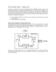
<strong>ME</strong> <strong>354</strong> <strong>Tutorial</strong>, <strong>Week#8</strong><strong>Brayton</strong> <strong>Cycle</strong> <strong>with</strong> <strong>Intercooling</strong>, <strong>Reheat</strong> & RegenerationA regenerative gas turbine <strong>with</strong> intercooling and reheat operates at steady state.Air enters the compressor at 100 kPa, 300 K <strong>with</strong> a mass flow rate of 5.807kg/s.The pressure ratio across the two-stage compressor is 10. The pressure ratioacross the two-stage turbine is also 10. The intercooler and reheater eachoperate at 300 kPa. At the inlets to the turbine stages, the temperature is 1400 K.The temperature at the inlet to the second compressor stage is 300 K. Theisentropic efficiency of each compressor and turbine stage is 80%. Theregenerator effectiveness is 80%. Determinea) The thermal efficiencyb) The net power developed (kW)c) The back work ratioStep 1: Draw a diagram to represent the system10RegeneratorQin,1Qin,2Compressor1Compressor245Combustor67<strong>Reheat</strong>Combustor892Intercooler3Turbine 1 Turbine 2W net,out1Q outTo better visualize what is happening during the cycle we can draw a T-s processdiagram.1
Step 4: CalculationsPart a)The thermal efficiency of the system can be expressed as the ratio of the sytem’snet-work output to the system’s heat input (we have heat inputs at the combustorAND the reheat combustor) as shown in Eq1. Note: the heat input that occursfrom location 4 to 5 is an internal energy transfer, getting its energy from location9 to 10 and thus does not qualify as a heat input into the system.ηth=qwin,1net,out+ qin,2(Eq1)The w net,out can be determined from the difference between the work output of theturbines and the work input to the compressors. The work for each of thesedevices can be determined from energy balances applied to the individual controlvolumes to obtain Eq2. Note: We have applied the steady operating conditionsassumption and the assumption that ∆ke & ∆pe ≈ 0 in each of our energybalances.w[ w + w ] −[ w + w ] = [ h − h ) + ( h − h )] − [(h − h ) + ( h − )]net, out t,1t,2c,1c,2(6 7 8 9 2 1 4h3= (Eq2)Since we are assuming that air is the working fluid and modeling it as an idealgas <strong>with</strong> constant specific heats at room temperature we can rewrite Eq2,applying the ideal gas relation for enthalpy difference between two states [e.g. h 2- h 1 =c p (T 2 -T 1 )], as shown in Eq3.→ wnet, out= cpT[( T6− T7) + ( T8− T9)] − [( T2− T1) + ( T4−3)](Eq3)The heat input can be determined from energy balances applied to the individualcontrol volumes (combustor and reheat combustor), similarly to what we did inEq2 & Eq3, to obtain Eq4.qin, 1 in,2(6 5 8 7 p 6 5 8T7+ q = h − h ) + ( h − h ) = c [( T − T ) + ( T − )] (Eq4)From Eq3 & Eq4 we can see that we must determine the temperatures oflocations 1 through 9 before we can calculate the thermal efficiency.Location 1T 1 =300 K (Given compressor 1 inlet conditions)Location 2We can use the isentropic efficiency of the compressor to determine thetemperature at Location 2 as shown in Eq5.h cspTsT2− h (2−1)1T2s− T1ηc= =→ T2= T1+(Eq5)h − h c ( T − T )η21p21c3
To find the temperature at Location 2 from Eq5 we must first determine thetemperature at Location 2 if the compression process were isentropic. We canuse an ideal gas relation for isentropic processes to find the temperature at state2s as shown below.T2sT1⎛ P2=⎜⎝ P1⎞⎟⎠k−1k→ T2s⎛ 300[ kPa]⎞= 300[]K ⎜ ⎟⎝100[kPa]⎠0.41.4= 410.62 KSubstituting this back into Eq5 we can solve for the temperature at Location 2.T2T2s− T1= T1+ηc410.62[ K]− 300[ K]= 300[ K]+= 438.3 K0.80Location 3T 3 =300 K (Given compressor 2 inlet conditions)Location 4Similarly to Location 2, we can use the isentropic efficiency of the compressor todetermine the temperature at Location 4, as shown in Eq6.ηch− hc( T − T )T − T4s3 p 4s34s3= =→ T4= T3+(Eq6)h4− h3cp( T4− T3)ηcTo find the temperature at Location 4 from Eq6 we must first determine thetemperature at Location 4 if the compression process was isentropic. We canuse the ideal gas relation for isentropic processes to find the temperature at state4s as shown below.T4sT3⎛ P4=⎜⎝ P3⎞⎟⎠k−1k→ T4s⎛1000[kPa]⎞= 300[]K ⎜ ⎟⎝ 300[ kPa]⎠0.41.4= 423.17 KSubstituting this back into Eq6 we can solve for the temperature at Location 4.T4= T3T4s− T3+ηc423.2[ K]− 300[ K]= 300[ K]+= 453.96 K0.80Location 5To find the temperature at Location 5 we can make use of the regenerator’seffectiveness, as shown in Eq7.4
T9sT8⎛ P9=⎜⎝ P8⎞⎟⎠k −1k→ T9s⎛ 100[ kPa]⎞= 1400[]K ⎜ ⎟⎝ 300[ kPa]⎠0.41.4= 1023 KSubstituting this back into Eq9 we can solve for the temperature at Location 9.T9 8 t(8 9sK= T −η T − T ) = 1400[ K]− (0.8)(1400[ K]−1023[]) = 1098.3 KLocation 5 cont’dWe can now go back to Eq7 and solve for the temperature at Location 5.T5 = T4+ εregen( T9− T4) = 453.96 + (0.8)(1098.3 −453.96) =969.43 KOur property table is now complete and we can solve for the thermal efficiency.kJW⎛ ⎡ ⎤⎞net, out = mair wnet,out= (5.807[ kg / s])⎜1.005⎟⎢ ( K [] K )kg K⎥627.7[ ] − 292. 26⎝ ⎣ • ⎦⎠T (K) P (kPa)1 300 1002 438.3 3002s 410.62 3003 300 3004 453.96 10004s 423.2 10005 969.43 10006 1400 10007 1074 3007s 992.51 3008 1400 3009 1098.3 1009s 1023 10010 100Substituting Eq3 and Eq4 into Eq1 we can solve for the thermal efficiency.6 7 8 9 2 1 4 3η th=( T6− T5) + ( T8− T7)=(430.57) + (326)627.7− 292.26→ η th==0.443 or 44.3%756.57Answer a)Part b)The net power developed <strong>with</strong> be the w net,out (Eq3) multiplied by the mass flowrate of air. We are given the mass flow rate of air in the problem statement asbeing 5.807 kg/s.[(T − T ) + ( T − T )] −[ ( T − T ) + ( T − T )] [(326)+ (301.7)] −[ (138.3) + (153.96)]6
=1957.6 kW Answer b)Part c)The back work ratio is defined as the ratio of compressor work to the turbinework.wc,in 292.26bwr = = =0.466 or 46.6% Answer c)w 627.7t,outStep 5: Concluding Remarks & Discussiona) The thermal efficiency was calculated as 0.443.b) The net power developed is 1957.6 kW.c) The back work ratio is 0.466.7