LVPED208008EN (web).pdf - studiecd.dk
LVPED208008EN (web).pdf - studiecd.dk
LVPED208008EN (web).pdf - studiecd.dk

Create successful ePaper yourself
Turn your PDF publications into a flip-book with our unique Google optimized e-Paper software.
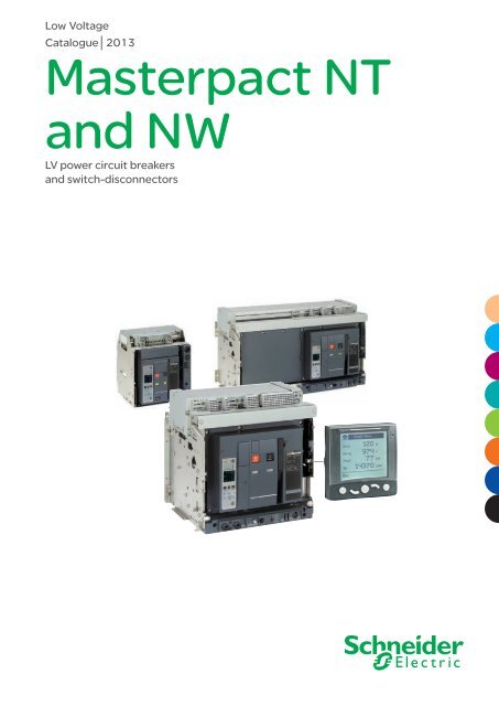
Low VoltageCatalogue│2013Masterpact NTand NWLV power circuit breakersand switch-disconnectors
Masterpact NT and NWThe standard for powercircuit breakersaround the world.Over the years, other major manufacturers have tried to keep up bydeveloping products incorporating Masterpact’s most innovative features,including the breaking principle, modular design and the use of compositematerials.In addition to the traditional features of power circuit breakers(withdrawability, discrimination and low maintenance), Masterpact NT andNW ranges offer built-in communications and metering functions, all inoptimised frame sizes.Masterpact NT and NW incorporate the latest technology to enhance bothperformance and safety. Easy to install, with user-friendly, intuitiveoperation and environment-friendly design, Masterpact NT and NW are,quite simply, circuit breakers of their time.I
Covering all your applicationsMasterpact meets the needs of all types of LV electrical distributionnetworks.Building> Hotels> Hospitals> Offices> RetailData Centresand NetworksIndustry> Mining and minerals> Automotive> Food and beverage> Chemical industryEnergy andInfrastructures> Airports> Oil and gas> Water> Electrical energy> MarineAn answer to specificapplications> 1000 V for mining applications> Direct current networks> Corrosion protection> Switch-disconnectors and earthing switches> Automatic transfer switching equipment(ATSE) for emergency power systems> High electrical endurance applications:Masterpact NT H2 is a high performancedevice offering high breaking capacity(Icu: 50 kA/480 V) and a high level ofdiscrimination, all in a small volume.Whenever high short circuitis involvedMasterpact UR is a low voltage ultra rapidopening circuit breaker. Its fault detection rateand its reaction speed mean that it will stop ashort circuit from developing. As a result, this isthe key component in very high powerinstallations equipped with a number of powersources connected in parallel.Masterpact UR truly comes into its own whenshort circuit currents can reach very high levelsand when continuity of service is a must:offshore installations, cement plants,petrochemical industry. It is also especiallysuited to electrical installations on boardmerchant.All standardsMasterpact is compliant with international standards IEC 60947-1 and 2, IEC 68230 for type 2 tropicalisation,UL489, ANSI, UL1066, CCC and GOST.II
Optimised volumesand ease of installationAiming at standardising electrical switchboards at a time wheninstallations are increasingly complex, Masterpact provides anunequalled simplicity, both concerning choice and installation.The smallest circuit breakerin the worldMasterpact NT innovates by offering all theperformance of a power circuit breaker in anextremely small volume. The 70 mm pole pitchmeans a three-pole drawout circuit breaker canbe installed in a switchboard section 400 mmwide and 400 mm deep.Retrofit solutionsMaximum securityThe arc chutes absorb the energy releasedduring breaking, thus limiting the stressesexerted on the installation.They filter and cool the gases produced,reducing effects perceptible from the outside.Optimised volumesUp to 4000 A, Masterpact NW circuit breakersare all the same size, the same as the old M08to 32 range.From 4000 A to 6300 A, there is just one size.More than60patents are used todesign Masterpact> Special connections terminals are available to replace a fixed or a drawout Masterpact M08 to 32 with a Masterpact NW,without modifying the busbars or the door cut-out.> "Plug and Play" retrofit solution : this solution enables retrofitting of Masterpact M units with considerably reducing on-siteintervention time and getting the performance of last generation device.The original Masterpact M chassis is kept (nointervention on the switchboard structure)Masterpact NW adapted for"Plug and Play" solutionMasterpact My 3200 A30 minutesand 2 easy operationsThe retrofit solutions use a factory modifiedand adapted Masterpact NW which is installedin Masterpact M’s original chassis.IV
Standardisation of the switchboardWith optimised sizes, the Masterpact NT and NW ranges simplify thedesign of switchboards and standardise the installation of devices:> a single connection layout for Masterpact NT> three connection layouts for Masterpact NW:• one from 800 to 3200 A• one for 4000 A• one up to 6300 A> horizontal or vertical rear connections can be modified on-site byturning the connectors 90° or they can even be replaced by frontconnection terminals> identical connection terminals for the fixed or draw-out version for eachrating (Masterpact NW)> front connection requires little space because the connectors notincrease the depth of the device.Practical installation solutionsThe Masterpact NW range further improves the installation solutions that have built the success of its predecessors:> incoming connection to top or bottom terminals> no safety clearance required> connection:• horizontal or vertical rear connection• front connection with minimum extra space• mixed front and rear connections> 115 mm pole pitch on all versions> no derating up to 55 °C and 4000 A.Compliance withenvironmentalrequirementsThe materials used forMasterpact are not potentiallydangerous to the environmentand are marked to facilitatesorting for recycling.Production facilities arenon-polluting in compliancewith the ISO 14001 standard.V
Monitoring and protectingyour low voltage networkMasterpact can be integrated in a general supervision systemto optimise your electrical installation.Micrologic control unitsAll Masterpact are equipped with a Micrologic electronic control unit that offers a complete setof protections and state of the art measurements.VI
Ensuring safety at any timeAll Masterpact circuit breakers are equipped with a Micrologic electronic control unit that offers all types of current andadvanced protection, measurement and communication. Protection functions are separated from the measurement functionsand are managed by an ASIC electronic component. This independence guarantees immunity from conducted or radiateddisturbances and ensures the highest degree of reliability.Maximising continuity of serviceBecause a LV power supply interruption is unacceptable especially in critical power applications, an automatic system isrequired for LV transfer switching. For your peace of mind, Masterpact enables automatic control and management of powersources in your low voltage distribution network guaranteeing the hi-reliability of your installation.Optimising the management of your electrical installationWhen equipped with a Micrologic type E, P or H, Masterpact can be integrated in a general supervision system to optimiseinstallation operation and maintenance. Alarms may be programmed for remote indications. Used with PowerLogic IONEnterprise software, you can exploit the electrical data (current, voltage, frequency, power, and power quality) to optimisecontinuity of service and energy management:> reduce energy and operations costs> improve power quality, reliability and uptime> optimise equipment use.EGX300 gateway-server or iRIO RTUThe EGX300 <strong>web</strong>-enabled gateway-server or the iRIORTU (remote terminal unit) can both be used as Ethernetcoupler for the PowerLogic System devices and for any othercommunicating devices operating under Modbus RS485protocol. Data is viewable via a standard <strong>web</strong> browser.PowerLogic ION EnterprisePowerLogic ION Enterprise software is a complete powermanagement solution for your facility or plant operations.It can be connected to Masterpact through Ethernet/Modbusprotocol.ASICMeasurement functions are controlledby an additional microprocessor.Protection functions are electronicallymanaged independently of measurementfunctions.An ASIC (Application-SpecificIntegrated Circuit) is commonto all trip units, which boostsimmunity to conductedor radiated interferenceand increases reliability.VII
Keep your Masterpact NT/NWfeatures year after year byperforming requestedmaintenanceTo maintain Masterpact’s operating and safety characteristics fromthe beginning to the end of its service life, Schneider Electric requeststhat systematic checks and periodic maintenance be carried out byqualified personnel, as indicated in the “Masterpact MaintenanceGuide”.The Maintenance Guide defines 3 types ofmaintenance :> the corrective maintenance repairs a systemin view of fulfilling a required function> the preventive maintenance consists incarrying out, at predetermined intervals, checksintended to reduce the probability of a failure ordeterioration in the operation of a system> the predictive maintenance, based on therecording and analysis of system parameters, isthe means to detect drift from the initial stateand significant trends. Using predictivemaintenance makes possible to anticipate onthe corrective action required to ensureequipment safety and continuity of service, andplan the action for the most convenient time.The Maintenance Guide is available onInternet (www.schneider-electric.com) andprovides detailed information on :> the types of maintenance required, dependingon the criticality of the protected circuit> the risks involved if the component ceases tooperate correctly> what is understood by the terms normal,improved and severe environment andoperating conditions> the periodic preventive maintenanceoperations that should be carried out undernormal environment and operating conditionsas well as the level of competence required forthe operations> the environment and operating conditions thataccelerate device ageing.VIII
Masterpact NT and NWGeneral contentsPresentation 2Functionsand characteristicsA-1InstallationrecommendationsB-1Dimensionsand connectionC-1Electrical diagrams D-1AdditionalcharacteristicsE-1Catalogue numbersand order formF-11
menulong timeshort timealarmPresentationGeneral overviewDetailed contentsPB100762-60A.epsDB101123.epsThis overview describes all the functions offered byMasterpact NT and NW devices. The two productfamilies have identical functions implemented using thesame or different components depending on the case.DB101124.epsDB127407.eps100 %Micrologic 5.0 E40 %Circuit breakers and switch-disconnectors page A-2bbRatings:vvMasterpact NT 630 to 1600 AvvMasterpact NW 800 to 6300 A.bbCircuit breakers type N1, H1, H2, H3, L1.bbSwitch-disconnectors type NA, HA, HF.bb3 or 4 poles.bbFixed or drawout versions.bbOption with neutral on the right.bbProtection derating.Micrologic control units page A-8Ammeter A and Energy E2.0 basic protection5.0 selective protection6.0 selective + earth-fault protection7.0 (1) selective + earth-leakage protectionPower meter P5.0 selective protection6.0 selective + earth-fault protection7.0 selective + earth-leakage protectionHarmonic meter H5.0 selective protection6.0 selective + earth-fault protection7.0 selective + earth-leakage protectionbbExternal sensor for earth-fault protection.bbRectangular sensor for earth-leakage protection.bbSetting options (long-time rating plug):vvlow setting 0.4 to 0.8 x Irvvhigh setting 0.8 to 1 x Irvvwithout long-time protection.bbExternal power-supply module.bbBattery module.(1) Only for ammeter A.PB106363A35.epsDB124583.epsPB103360.epsPower Meter page A-20Masterpact equipped with Micrologic 2 / 5 / 6 trip units offer type A (ammeter) or E(energy) metering functions as well as communication. Using Micrologic sensorsand intelligence, Masterpact provides access to measurements of all the mainelectrical parameters on the built-in screen, on a dedicated FDM display unit or viathe communication system.Operating assistance page A-22Integration of measurement functions provides operators with operating assistancefunctions including alarms tripped by user-selected measurement values, timestampedevent tables and histories, and maintenance indicators.Switchboard display unit page A-23The main measurements can be read on the built-in screen of Micrologic 2 / 5 / 6 / 7trip units. They can also be displayed on the FDM switchboard display unit along withpop-up windows signalling the main alarms.Portable data acquisition page A-28bbMasterpact and GetnSet.Communication page A-30bbCOM option in Masterpact.bbMasterpact in a communication network.2
PB104347A55.epsPB104348A55.epsPB104353A55.epsConnections page A-37bbRear connection (horizontal or vertical).bbFront connection.bbMixed connections.bbOptional accessories:vvbare-cable connectors and connector shieldsvvterminal shieldsvvvertical-connection adaptersvvcable-lug adaptersvvinterphase barriersvvspreadersvvdisconnectable front-connection adaptervvsafety shutters, shutter locking blocks, shutterposition indication and locking.Locking page A-41bbPushbutton locking by padlockable transparentcover.bbOFF-position locking by padlock or keylock.bbChassis locking in disconnected position by keylock.bbChassis locking in connected, disconnectedand test positions.bbDoor interlock (inhibits door opening with breakerin connected position).bbRacking interlock (inhibits racking with door open).bbRacking interlock between crank and OFFpushbutton.bbAutomatic spring discharge before breaker removal.bbMismatch protection.Indication contacts page A-43bbStandard or low-level contacts:vvON/OFF indication (OF)v v“fault trip” indication (SDE)vvcarriage switches for connected(CE) disconnected (CD) and test(CT) positions.bbProgrammable contacts:vv2 contacts (M2C)vv6 contacts (M6C).DB101111.epsM2C contact. OF contact.DB101156.epsDB101149.epsDB101109.epsDB101110.epsDB101112.epsDB101147.epsDB101150.epsPB104349A55.epsRemote operation page A-45bbRemote ON/OFF:vvgear motorvvXF closing or MX opening voltage releasesvvPF ready-to-close contactoptions:- RAR automatic or RES electrical remote reset- BPFE electrical closing pushbutton.bbRemote tripping function:vvMN voltage release- standard- adjustable or non-adjustable delayGear motor.vvor second MX voltage release.DB101113.epsDb101114.epsMX, XF and MN voltagereleases.Accessories page A-49bbAuxiliary terminal shield.bbOperation counter.bbEscutcheon.bbTransparent cover for escutcheon.bbEscutcheon blanking plate.DB101115.eps3
TOOLSEcodialEcodial software is dedicated to LV electrical installationcalculation in accordance with the IEC60364international standard or national standards.This 4 th generation, "Ecodial Advance Calculation 4",offers a new ergonomic and new features:p poperating mode that allows easy calculation in caseof installation with different type of sources(parallel transformers, back-up generators…)p pdiscrimination analysis associating curves checkingand discrimination tablesp pdirect access to protection settings including residualcurrent protectionsp peasy selection of alternate solutions or manualselection of a product.
Masterpact NT and NWFunctions and characteristicsPresentation 2Circuit breakers and switch-disconnectorsNT06 to NT16 and NW08 to NW63 A-2Circuit breakers and switch-disconnectors characteristicsNT06 to NT16 A-4NW08 to NW63 A-6Micrologic control unitsOverview of functions A-8Micrologic A “ammeter” A-10Micrologic E “energy” A-12Micrologic P “power” A-14Micrologic H “harmonics” A-18Power Meter functionsMicrologic A/E/P/H control unit with COM option (BCM ULP) A-20Operating-assistance functionsMicrologic A/E/P/H control unit with COM option (BCM ULP) A-22Switchboard-display functionsMicrologic A/E/P/H control unit with COM option (BCM ULP) A-23Micrologic control unitsAccessories and test equipment A-25Portable data acquisitionMasterpact and GetnSet A-28CommunicationCOM option in Masterpact A-30Overview of functions A-31Masterpact communicationNetworks and sofware A-32RSU and RCU utilities A-34Supervision software A-35Communication wiring system A-36ConnectionsOverview of solutions A-37Accessories A-38LockingOn the device A-41On the chassis A-42Indication contacts A-43Remote operationRemote ON / OFF A-45Remote tripping A-48Accessories A-49Source-changeover systemsPresentation A-50Mechanical interlocking A-51Electrical interlocking A-53Standard configuration A-54Associated automatic controllers A-55Masterpact NW with corrosion protection 800-4000 A A-56Earthing switch Masterpact A-58Installation recommendations B-1Dimensions and connection C-1Electrical diagrams D-1Additional characteristics E-1Catalogue numbers and order form F-1A-1
Functionsand characteristicsCircuit breakersand switch-disconnectorsNT06 to NT16 and NW08 to NW63NT and NW selection criteriaMasterpact NTStandard applicationsMasterpact NWStandard applicationsNT06, NT08, NT10, NT12, NT16 NT06, NT08, NT10 NW08...NW16 NW08...NW40H1 H2 L1 N1 H1Type of applicationStandard applicationswith low short-circuitcurrentsApplications withmedium-levelshort-circuit currentsLimiting circuit breakerfor protection ofcable-type feeders orupgraded transformerratingsStandard applicationswith low short-circuitcurrentsCircuit breaker forindustrial sites withhigh short-circuitcurrentsIcu/Ics at 440 V 42 kA 50 kA 130 kA 42 kA 65 kAIcu/Ics at 1000 V - - - - -Icu/Ics at 500 V DC L/R < 15 ms - - - - -Position of neutral Left Left Left Left Left or rightFixed F F F F FDrawout D D D D DSwitch-disconnector version Yes No No Yes YesFront connection Yes Yes Yes Yes Yes up to 3200 ARear connection Yes Yes Yes Yes YesType of Micrologic control unit A, E, P, H A, E, P, H A, E, P, H A, E, P, H A, E, P, HMasterpact NT06 to NT16 installation characteristicsCircuit breaker NT06, NT08, NT10 NT12, NT16Type H1 H2 L1 H1 H2ConnectionDrawout FC b b b b bRC b b b b bFixed FC b b b b bRC b b b b bDimensions (mm) H x W x DDrawout 3P 322 x 288 x 2774P 322 x 358 x 277Fixed 3P 301 x 276 x 1964P 301 x 346 x 196Weight (kg) (approximate)Drawout 3P/4P 30/39Fixed 3P/4P 14/18Masterpact NW08 to NW63 installation characteristicsCircuit breaker NW08, NW10, NW12, NW16 NW20Type N1 H1 H2 L1 H10 H1 H2 H3 L1 H10ConnectionDrawout FC b b b b - b b b b -RC b b b b b b b b b bFixed FC b b b - - b b - - -RC b b b - - b b - - -Dimensions (mm) H x W x DDrawout 3P 439 x 441 x 3954P 439 x 556 x 395Fixed 3P 352 x 422 x 2974P 352 x 537 x 297Weight (kg) (approximate)Drawout 3P/4P 90/120Fixed 3P/4P 50/65(1) Except 4000.A-2
Special applicationsNW H10NW H2 with NW10...NW40H2 H3 L1 corrosion N DC H DCprotectionHigh-performancecircuit breaker forheavy industrywith highshort-circuitcurrentsIncoming devicewith very highperformance forcriticalapplicationsLimiting circuitbreaker forprotection ofcable-type feedersor upgradedtransformerratings1000 V systems,e.g. mines andwind powerEnvironments withhigh sulphurcontentsNW earthingswitchDC system DC system Installationearthing100 kA 150 kA 150 kA - 100 kA - - -- - - 50 kA - - - -- - - - - 35 kA 85 kA -Left or right Left Left Left Left - - -F - - - - F F -D D D D D D D DYes Yes No Yes Yes Yes Yes YesYes up to 3200 A Yes up to 3200 A Yes up to 3200 A No Yes up to 3200 A No No Yes up to 3200 AYes Yes Yes Yes Yes Yes Yes YesA, E, P, H A, E, P, H A, E, P, H A, E, consult usfor P and HA, E, P, H DC Micrologic DC Micrologic -NW25, NW32, NW40NW40b, NW50,NW63H1 H2 H3 H10 H1 H2b (1) b (1) b (1) - - -b b b b b bb (1) b (1) - - - -b b - - b b479 x 786 x 395479 x 1016 x 395352 x 767 x 297352 x 997 x 297225/300120/160A-3
Functionsand characteristicsCircuit breakersand switch-disconnectorscharacteristicsNT06 to NT16PB106365A49.epsCommon characteristicsNumber of poles 3/4Rated insulation voltage (V) Ui 1000Impulse withstand voltage (kV) Uimp 12Rated operational voltage (V AC 50/60 Hz) Ue 690Suitability for isolation IEC 60947-2Degree of pollution IEC 60664-1 3Basic sweatchgearCircuit-breaker as per IEC 60947-2Rated current (A) In at 40 °C/50 °C (1)Rating of 4th pole (A)Sensor ratings (A)Type of circuit breakerUltimate breaking capacity (kA rms) Icu 220/415 VV AC 50/60 Hz440 V525 V690 VRated service breaking capacity (kA rms) Ics % IcuUtilisation categoryRated short-time withstand current (kA rms)V AC 50/60 HzIcw0.5 s1 s3 sIntegrated instantaneous protection (kA peak ±10 %)Rated making capacity (kA peak) Icm 220/415 VV AC 50/60 Hz440 V525 V690 VBreak time (ms) between tripping order and arc extinctionClosing time (ms)Circuit breaker as per NEMA AB1Breaking capacity (kA)V AC 50/60 Hz240 V480 V600 V(1) 50 °C: rear vertical connected. Refer to temperaturederating tables for other connection types.(2) See the current-limiting curves in the “additionalcharacteristics” section.(3) SELLIM system.(4) Available for 480 V NEMA.(5) Suitable for motor control (direct-on-line starting).(6) Icw 42 kA/1 s available from july 2013, 36 kA/1 sbefore july - please contact us to confirm the date.Switch-disconnector as per IEC 60947-3 and Annex AType of switch-disconnectorRated making capacity (kA peak) Icm 220 VAC23A/AC3 category V AC 50/60 Hz440 V525/690 VRated short-time withstand current (kA rms) Icw 0.5 sAC23A/AC3 category V AC 50/60 Hz1 s3 sUltimate breaking capacity Icu (kA rms) with an external protection relay 690 VMaximum time delay: 350 msMechanical and electrical durability as per IEC 60947-2/3 at In/IeService life Mechanical without maintenanceC/O cycles x 1000Type of circuit breakerRated currentIn (A)C/O cycles x 1000 Electrical without maintenance 440 V (4)IEC 60947-2690 VType of circuit breaker or switch-disconnectorRated operationnal current Ie (A) AC23AC/O cycles x 1000 Electrical without maintenance 440 V (4)IEC 60947-3690VType of circuit breaker or switch-disconnectorRated operationnal current Ie (A) AC3 (5)Motor power380/415 V (kW)440 V (kW)C/O cycles x 1000 Electrical without maintenance 440 V (4)IEC 60947-3 Annex M/IEC 60947-4-1690 VA-4
Sensor selectionSensor rating (A) 250 (1) 400 630 800 1000 1250 1600Ir threshold setting (A) 100 to 250 160 to 400 250 to 630 320 to 800 400 to 1000 500 to 1250 640 to 1600(1) For circuit breaker NT02, please consult us.NT06 NT08 NT10 NT12 NT16630 800 1000 1250 1600630 800 1000 1250 1600400 to 630 400 to 800 400 to 1000 630 to 1250 800 to 1600H1 H2 L1 (2) H1 H242 50 150 42 5042 50 130 42 5042 42 100 42 4242 42 25 42 42100 % 100 %B B A B B42 42 (6) 10 42 42 (6)42 42 (6) - 42 42 (6)24 20 - 24 20- 90 10 x In (3) - 9088 105 330 88 10588 105 286 88 10588 88 220 88 8888 88 52 88 8825 25 9 25 25< 50 < 5042 50 150 42 5042 50 100 42 5042 42 25 42 42HAHA75 7575 7575 7536 3636 3620 2036 3612.5H1 H2 L1 H1 H2 L1 H1 H2 L1 H1 H2 H1 H2630 800 1000 12506 6 3 6 6 3 6 6 3 6 6 6 63 3 2 3 3 2 3 3 2 3 3 3 3H1/H2/HA630 800 1000 1250 16006 6 6 6 33 3 3 3 1H1/H2/HA500 630 800 1000 1000y 250 250 to 335 335 to 450 450 to 560 450 to 560y 300 300 to 400 400 to 500 500 to 630 500 to 6306-A-5
PB106363A35.epsPB106362A65.epsFunctionsand characteristics(1) 50 °C: rear vertical connected. Refer to temperaturederating tables for other connection types.(2) See the current-limiting curves in the “additionalcharacteristics” section.(3) Equipped with a trip unit with a making currentof 90 kA peak.(4) External protection must comply with permissible thermalconstraints of the circuit breaker (please consult us).No fault-trip indication by the SDE or the reset button.(5) Available for 480 V NEMA.(6) Suitable for motor control (direct-on-line starting).A-6Circuit breakersand switch-disconnectorscharacteristicsNW08 to NW63Common characteristicsNumber of poles 3/4Rated insulation voltage (V) Ui 1000 1250 for H10, HA10Impulse withstand voltage (kV) Uimp 12 12Rated operational voltage (V AC 50/60 Hz) Ue 690 1150 for H10, HA10Suitability for isolation IEC 60947-2Degree of pollution IEC 60664-1 4 (1000 V) / 3 (1250 V)Basic circuit-breakerCircuit-breaker as per IEC 60947-2Rated current (A) at 40 °C / 50 °C (1)Rating of 4th pole (A)Sensor ratings (A)Type of circuit breakerUltimate breaking capacity (kA rms)V AC 50/60 HzRated service breaking capacity (kA rms) Ics % IcuUtilisation categoryRated short-time withstand current (kA rms)V AC 50/60 HzIcw 1 s3 sIntegrated instantaneous protection (kA peak ±10 %)Rated making capacity (kA peak)V AC 50/60 HzBreak time (ms) between tripping order and arc extinctionClosing time (ms)Circuit-breaker as per NEMA AB1Breaking capacity (kA)V AC 50/60 HzIcuIcm220/415/440 V525 V690 V1150 V220/415/440 V525 V690 V1150 V240/480 V600 VUnprotected circuit-breakerTripping by shunt trip as per IEC 60947-2Type of circuit breakerUltimate breaking capacity (kA rms) V AC 50/60 Hz Icu 220...690 VRated service breaking capacity (kA rms) Ics % IcuRated short-time withstand current (kA rms) Icw 1 s3 sOverload and short-circuit protectionExternal protection relay: short-circuit protection, maximum delay: 350 ms (4)Rated making capacity (kA peak) V AC 50/60 Hz Icm 220...690 VSwitch-disconnector as per IEC 60947-3 and Annex AType of switch-disconnectorRated making capacity (kA peak)AC23A/AC3 category V AC 50/60 HzRated short-time withstand current (kA rms)AC23A/AC3 category V AC 50/60 HzIcmIcw220...690 V1150 V1 s3 sEarthing switchLatching capacity (kA peak) 135Rating short time withstand (kA rms) Icw 1 s3 sMechanical and electrical durability as per IEC 60947-2/3 at In/IeService life Mechanical with maintenanceC/O cycles x 1000without maintenanceType of circuit breakerRated currentIn (A)C/O cycles x 1000 Electrical without maintenance 440 V (5)IE C 60947-2690 V1150 VType of circuit breaker or switch-disconnectorRated operational current Ie (A) AC23AC/O cycles x 1000 Electrical without maintenance 440 V (5)IEC 60947-3690 VType of circuit breaker or switch-disconnectorRated operational current Ie (A) AC3 (6)Motor power380/415 V (kW)440 V (5) (kW)690 V (kW)C/O cycles x 1000 Electrical without maintenance 440/690 V (5)IEC 60947-3 Annex M/IEC 60947-4-1
Sensor selectionSensor rating (A) 250 (1) 400 630 800 1000 1250 1600 2000 2500 3200 4000 5000 6300Ir threshold setting(A) 100 160 250 320 400 500 630 800 1000 1250 1600 2000 2500to 250 to 400 to 630 to 800 to 1000 to 1250 to 1600 to 2000 to 2500 to 3200 to 4000 to 5000 to 6300(1) For circuit breaker NW02, please consult us.NW08 NW10 NW12 NW16 NW20 NW25 NW32 NW40 NW40b NW50 NW63800 1000 1250 1600 2000 2500 3200 4000 4000 5000 6300800 1000 1250 1600 2000 2500 3200 4000 4000 5000 6300400to 800400to 1000630to 1250800 to 1600 1000 to 2000 1250to 25001600to 32002000 to 4000 2000to 40002500to 50003200to 6300N1 H1 H2 L1 (2) H10 N1 H1 H2 H3 L1 (2) H10 H1 H2 H3 H10 H1 H242 65 100 150 - 42 65 100 150 150 - 65 100 150 - 100 15042 65 85 130 - 42 65 85 130 130 - 65 85 130 - 100 13042 65 85 100 - 42 65 85 100 100 - 65 85 100 - 100 100- - - - 50 - - - - - 50 - - - 50 - -100 % 100 % 100 % 100 %B B B B42 65 85 30 50 42 65 85 65 30 50 65 85 65 50 100 10022 36 50 30 50 22 36 75 65 30 50 65 75 65 50 100 100- - 190 80 - - - 190 150 80 - - 190 150 - - 27088 143 220 330 - 88 143 220 330 330 - 143 220 330 - 220 33088 143 187 286 - 88 143 187 286 286 - 143 187 286 - 220 28688 143 187 220 - 88 143 187 220 220 - 143 187 220 - 220 220- - - - 105 - - - - - 105 - - - 105 - -25 25 25 10 25 25 25 25 25 10 25 25 25 25 25 25 25< 70 < 70 < 70 < 70 < 8042 65 100 150 - 42 65 100 150 150 - 65 100 150 - 100 15042 65 85 100 - 42 65 85 100 100 - 65 85 100 - 100 100HA HF (3) HA HF (3) HA HF (3) HA50 85 50 85 55 85 85100 % 100 % 100 % 100 %50 85 50 85 55 85 8536 50 36 75 55 75 85- - - - - - -105 187 105 187 121 187 187NW08/NW10/NW12/NW16 NW20 NW25/NW32/NW40 NW40b/NW50/NW63NA HA HF HA10 HA HF HA10 HA HF HA10 HA88 105 187 - 105 187 - 121 187 - 187- - - 105 - - 105 - - 105 -42 50 85 50 50 85 50 55 85 50 85- 36 50 50 36 75 50 55 75 50 8560 Hz50 Hz25 20 1012.5 10 5N1/H1/H2 L1 H10 N1/H1/H2 H3 L1 H10 H1/H2 H3 H10 H1 H2800/1000/1250/1600 2000 2500/3200/4000 4000b/5000/630010 3 - 8 2 3 - 5 1.25 - 1.5 1.510 3 - 6 2 3 - 2.5 1.25 - 1.5 1.5- - 0.5 - - - 0.5 - - 0.5 - -H1/H2/NA/HA/HF H1/H2/H3/HA/HF H1/H2/H3/HA/HF H1/H2/HA800/1000/1250/1600 2000 2500/3200/4000 4000b/5000/630010 8 5 1.510 6 2.5 1.5H1/H2/NA/HA/HFH1/H2/H3/HA/HF800 1000 1250 1600 2000335 to 450 450 to 560 560 to 670 670 to 900 900 to 1150400 to 500 500 to 630 500 to 800 800 to 1000 1000 to 1300y 800 800 to 1000 1000 to 1250 1250 to 1600 1600 to 20006A-7
Functionsand characteristicsMicrologic control unitsOverview of functionsAll Masterpact circuit breakers are equipped with aMicrologic control unit that can be changed on site.Control units are designed to protect Power circuitsand loads. Alarms may be programmed for remoteindications.Measurements of current, voltage, frequency, powerand power quality optimise continuity of service andenergy management.DependabilityIntegration of protection functions in an ASIC electronic component used in allMicrologic control units guarantees a high degree of reliability and immunity toconducted or radiated disturbances.On Micrologic A, E, P and H control units, advanced functions are managed byan independent microprocessor.AccessoriesCertain functions require the addition of Micrologic control unit accessories,described on page A-25.The rules governing the various possible combinations can be found in thedocumentation accessible via the Products and services menu of thewww.schneider-electric.com <strong>web</strong> site.Micrologic name codes2.0 EX Y ZDB101116.epsCurrent protectionMicrologic 2: basic protectionProtection:long time+ instantaneousX: type of protectionbb2 for basic protectionbb5 for selective protectionbb6 for selective + earth-fault protectionbb7 for selective + earth-leakage protection.Y: control-unit generationIdentification of the control-unit generation.“0” signifies the first generation.Z: type of measurementbbA for “ammeter”bbE for “energy”bbP for “power meter”bbH for “harmonic meter”.DB101117.epsMicrologic 5: selective protectionProtection:long time+ short time+ instantaneousPB100772-32.epsPB106351A32.epsMicrologic 6: selective + earth-fault protectionDB101117.epsDB101118.epsProtection:long time+ short time+ instantaneous+ earth faultMicrologic 7: selective + earth-leakage protectionDB101117.epsDB101119.epsProtection:long time+ short time+ instantaneous+ earth leakage up to 3200AA-8
menulong timeinstantaneousmenulong timeshort timealarmalarmmenulong timeinstantaneousmenulong timeshort timemenulong timeshort timeground faultalarmalarmalarmMeasurements and programmable protectionA: ammeterbbI 1, I 2, I 3, I N, I earth-fault, I earth-leakageand maximeter for these measurementsbbfault indicationsbbsettings in amperes and in seconds.E: Energy P: A + power meter + programmable protectionbbincorporates all the rms bbmeasurements of V, A, W, VAR, VA, Wh, VARh, VAh, Hz, V peak, A peak, power factor andmeasurements of maximeters and minimetersMicrologic A, plus voltage, bbIDMTL long-time protection, minimum and maximum voltage and frequency, voltagepower factor, power andand current imbalance, phase sequence, reverse powerenergy meteringbbload shedding and reconnection depending on power or currentmeasurementsbbmeasurements of interrupted currents, differentiated fault indications,bbcalculates the currentdemand valuemaintenance indications, H: P + harmonicsb b"Quickview" function forevent histories and bbpower quality: fundamentals, distortion, amplitude andthe automatic cyclicaltime-stamping, etc. phase of harmonics up to the 31st orderdisplay of the most usefulbbwaveform capture after fault, alarm or on requestvalues (as standard or bybbenhanced alarm programming: thresholds and actions.selection).2.0 ADB127404.epsMicrologic 2.0 A2.0 EDB127405.epsMicrologic 2.0 E100 %100 %40 %40 %5.0 AMicrologicDB127406.eps5.0 A5.0 EMicrologicDB127407.eps5.0 E5.0 PDB101122.eps5.0 HDB101122.eps100 %100 %40 %40 %6.0 ADB101123.eps6.0 EDB127408.epsMicrologic 6.0 E6.0 PDB101124.eps6.0 HDB101124.eps100 %40 %7.0 ADB101123.eps7.0 PDB101124.eps7.0 HDB101124.epsA-9
Functionsand characteristicsMicrologic control unitsMicrologic A “ammeter”DB401463.epsMicrologic A control units protect power circuits.They also offer measurements, display, communicationand current maximeters. Version 6 provides earth-faultprotection, version 7 provides earth-leakage protection.1 long-time threshold and tripping delay2 overload alarm (LED) at 1,125 Ir3 short-time pick-up and tripping delay4 instantaneous pick-up5 earth-leakage or earth-fault pick-up and tripping delay6 earth-leakage or earth-fault test button7 long-time rating plug screw8 test connector9 lamp test, reset and battery test10 indication of tripping cause11 digital display12 three-phase bargraph and ammeter13 navigation buttons"Ammeter" measurementsMicrologic A control units measure the true (rms) value of currents.They provide continuous current measurements from 0.2 to 1.2 In and are accurateto within 1.5 % (including the sensors).A digital LCD screen continuously displays the most heavily loaded phase (Imax) ordisplays the I1, I2, I3, IN, Ig,I∆n, stored-current (maximeter) and setting values bysuccessively pressing the navigation button.The optional external power supply makes it possible to display currents < 20 % In.Below 0.1 In, measurements are not significant. Between 0.1 and 0.2 In, accuracychanges linearly from 4 % to 1.5 %.Communication optionIn conjunction with the COM communication option, the control unit transmits thefollowing:bbsettingsbball “ammeter” measurementsbbtripping causesbbmaximeter readings.ProtectionProtection thresholds and delays are set using the adjustment dials.Overload protectionTrue rms long-time protection.Thermal memory: thermal image before and after tripping.Setting accuracy may be enhanced by limiting the setting range using a differentlong-time rating plug.Overload protection can be cancelled using a specific LT rating plug "Off".Short-circuit protectionShort-time (rms) and instantaneous protection.Selection of I2t type (ON or OFF) for short-time delay.Earth-fault protectionResidual or source ground return earth fault protection.Selection of I2t type (ON or OFF) for delay.Residual earth-leakage protection (Vigi).Operation without an external power supply.q Protected against nuisance tripping.k DC-component withstand class A up to 10 A.Neutral protectionOn three-pole circuit breakers, neutral protection is not possible.On four-pole circuit breakers, neutral protection may be set using a three-positionswitch: neutral unprotected (4P 3d), neutral protection at 0.5 Ir (4P 3d + N/2), neutralprotection at Ir (4P 4d).Zone selective interlocking (ZSI)A ZSI terminal block may be used to interconnect a number of control units to providetotal discrimination for short-time and earth-fault protection, without a delay beforetripping.Overload alarmA yellow alarm LED goes on when the current exceeds the long-time trip threshold.Fault indicationsLEDs indicate the type of fault:bboverload (long-time protection Ir)bbshort-circuit (short-time Isd or instantaneous li protection)bbearth fault or earth leakage (Ig or I∆n)bbinternal fault (Ap).Battery powerThe fault indication LEDs remain on until the test/reset button is pressed. Undernormal operating conditions, the battery supplying the LEDs has a service life ofapproximately 10 years.TestA mini test kit or a portable test kit may be connected to the test connector on thefront to check circuit-breaker operation. For Micrologic 6.0 A and 7.0 A control units,the operation of earth-fault or earth-leakage protection can be checked by pressingthe test button located above the test connector.Note: Micrologic A control units come with a transparentlead-seal cover as standard.A-10
ProtectionMicrologic 2.0 ALong timeCurrent setting (A) 0.4 0.5 0.6 0.7 0.8 0.9 0.95 0.98 1Tripping between 1.05 and 1.20 x IrOther ranges or disable by changing long-time rating plugTime setting tr (s) 0.5 1 2 4 8 12 16 20 24Time delay (s) Accuracy: 0 to -30 % 1.5 x Ir 12.5 25 50 100 200 300 400 500 600Accuracy: 0 to -20 % 6 x Ir 0.7 (1) 1 2 4 8 12 16 20 24Accuracy: 0 to -20 % 7.2 x Ir 0.7 (2) 0.69 1.38 2.7 5.5 8.3 11 13.8 16.6Thermal memory20 minutes before and after tripping(1) 0 to -40 % - (2) 0 to -60 %InstantaneousPick-up (A) Isd = Ir x … 1.5 2 2.5 3 4 5 6 8 10Accuracy: ±10 %Time delayMax resettable time: 20 msMax break time: 80 msProtectionMicrologic 5.0 / 6.0 / 7.0 ALong timeMicrologic 5.0 / 6.0 / 7.0 ACurrent setting (A) Ir = In x … 0.4 0.5 0.6 0.7 0.8 0.9 0.95 0.98 1Tripping between 1.05 and 1.20 x IrOther ranges or disable by changing long-time rating plugTime setting tr (s) 0.5 1 2 4 8 12 16 20 24Time delay (s) Accuracy: 0 to -30 % 1.5 x Ir 12.5 25 50 100 200 300 400 500 600Accuracy: 0 to -20 % 6 x Ir 0.7 (1) 1 2 4 8 12 16 20 24Accuracy: 0 to -20 % 7.2 x Ir 0.7 (2) 0.69 1.38 2.7 5.5 8.3 11 13.8 16.6Thermal memory20 minutes before and after tripping(1) 0 to -40 % - (2) 0 to -60 %Short timePick-up (A) Isd = Ir x … 1.5 2 2.5 3 4 5 6 8 10Accuracy: ±10 %Time setting tsd (s) Settings I 2 t Off 0 0.1 0.2 0.3 0.4I 2 t On - 0.1 0.2 0.3 0.4Time delay (ms) at 10 x Ir tsd (max resettable time) 20 80 140 230 350(I 2 t Off or I 2 t On) tsd (max break time) 80 140 200 320 500InstantaneousPick-up (A) Ii = In x … 2 3 4 6 8 10 12 15 offAccuracy: ±10 %Time delayMax resettable time: 20 msMax break time: 50 msEarth faultMicrologic 6.0 APick-up (A) Ig = In x … A B C D E F G H JAccuracy: ±10 % In y 400 A 0.3 0.3 0.4 0.5 0.6 0.7 0.8 0.9 1400 A < In < 1250 A 0.2 0.3 0.4 0.5 0.6 0.7 0.8 0.9 1In u 1250 A 500 640 720 800 880 960 1040 1120 1200Time setting tg (s) Settings I 2 t Off 0 0.1 0.2 0.3 0.4I 2 t On - 0.1 0.2 0.3 0.4Time delay (ms) tg (max resettable time) 20 80 140 230 350at In or 1200 A (I 2 t Off or I 2 t On) tg (max break time) 80 140 200 320 500Residual earth leakage (Vigi)Micrologic 7.0 ASensitivity (A) IDn 0.5 1 2 3 5 7 10 20 30Accuracy: 0 to -20 %Time delay Dt (ms) Settings 60 140 230 350 800Dt (max resettable time) 60 140 230 350 800Dt (max break time) 140 200 320 500 1000DB101129.epsDB101128.epsDB101127.epsDB101126.epsAmmeterMicrologic 2.0 / 5.0 / 6.0 / 7.0 AType of measurements Range AccuracyInstantaneous currents I1, I2, I3, IN 0.2 x In to 1.2 x In ±1.5 %Ig (6.0 A) 0.2 x In to In ±10 %IDn (7.0 A) 0 to 30 A ±1.5 %Current maximeters of I1, I2, I3, IN 0.2 x In to 1.2 x In ±1.5 %Note: all current-based protection functions require no auxiliary source.The test / reset button resets maximeters, clears the tripping indication and tests the battery.A-11
Functionsand characteristicsMicrologic control unitsMicrologic E “energy”DB126649.epsMicrologic E control units protect power circuits. Theyalso offer measurements, display, communication andcurrent maximeters. Version 6 provides earth-faultprotection.14151 long-time threshold and tripping delay2 overload alarm (LED) at 1,125 Ir3 short-time pick-up and tripping delay4 instantaneous pick-up5 earth-leakage or earth-fault pick-up and tripping delay6 earth-leakage or earth-fault test button7 long-time rating plug screw8 test connector9 lamp test, reset and battery test10 indication of tripping cause11 digital display12 three-phase bargraph and ammeter13 navigation button "quick View" (only with Micrologic E)14 navigation button to view menu contents15 navigation button to change menu(1) Display on FDM only.Note: Micrologic E control units come with a transparentlead-seal cover as standard.A-12"Energy meter" measurementsIn addition to the ammeter measurements of Micrologic AMicrologic E control units measure and display:bbcurrent demandbbvoltages: phase to phase, phase to neutral, average (1) and unbalanced (1)bbinstantaneous power: P, Q, Sbbpower factor: PFbbpower demand: P demandbbenergy: Ep, Eq (1) , Es (1) .Accuracy of active energy Ep is 2 % (including the sensors). The range ofmeasurement is the same as current with Micrologic A, depending of an externalpower supply module (24 V DC).Communication optionIn conjunction with the COM communication option, the control unit transmits thefollowing:bbsettingsbball "ammeter" and "energy" measurementsbbenable connection to FDMbbtripping causesbbmaximeter / minimeter readings.ProtectionProtection thresholds and delays are set using the adjustment dials.Overload protectionTrue rms long-time protection.Thermal memory: thermal image before and after tripping.Setting accuracy may be enhanced by limiting the setting range using a differentlong-time rating plug. Overload protection can be cancelled using a specific LTrating plug "Off".Short-circuit protectionShort-time (rms) and instantaneous protection.Selection of I 2 t type (ON or OFF) for short-time delay.Earth-fault protectionSource ground return earth fault protection.Selection of I 2 t type (ON or OFF) for delay.Neutral protectionOn three-pole circuit breakers, neutral protection is not possible.On four-pole circuit breakers, neutral protection may be set using a three-positionswitch: neutral unprotected (4P 3d), neutral protection at 0.5 Ir (4P 3d + N/2), neutralprotection at Ir (4P 4d).Zone selective interlocking (ZSI)A ZSI terminal block may be used to interconnect a number of control units to providetotal discrimination for short-time and earth-fault protection, without a delay beforetripping.Overload alarmA yellow alarm LED goes on when the current exceeds the long-time trip threshold.M2C programmable contactsThe M2C (two contacts) programmable contacts may be used to signal envents(Ir, Isd, Alarm Ir, Alarm Ig, Ig). They can be programmed using the keypad on theMicrologic E control unit or remotely using the COM option (BCM ULP).Fault indicationsLEDs indicate the type of fault:bboverload (long-time protection Ir)bbshort-circuit (short-time Isd or instantaneous li protection)bbearth fault (Ig)bbinternal fault (Ap).Trip historyThe trip history displays the list of the last 10 trips. For each trip, the followingindications are recorded and displayed:bbthe tripping cause: Ir, Isd, li, Ig or Auto-protection (Ap) tripsbbthe date and time of the trip (requires communication option).Battery powerThe fault indication LEDs remain on until the test/reset button is pressed. Undernormal operating conditions, the battery supplying the LEDs has a service life ofapproximately 10 years.TestA mini test kit or a portable test kit may be connected to the test connector on thefront to check circuit-breaker operation. For Micrologic 6.0 E control units, theoperation of earth-fault or earth-leakage protection can be checked by pressing thetest button located above the test connector.
ProtectionMicrologic 2.0 ELong timeCurrent setting (A) 0.4 0.5 0.6 0.7 0.8 0.9 0.95 0.98 1Tripping between 1.05 and 1.20 x IrOther ranges or disable by changing long-time rating plugTime setting tr (s) 0.5 1 2 4 8 12 16 20 24Time delay (s) Accuracy: 0 to -30 % 1.5 x Ir 12.5 25 50 100 200 300 400 500 600Accuracy: 0 to -20 % 6 x Ir 0.7 (1) 1 2 4 8 12 16 20 24Accuracy: 0 to -20 % 7.2 x Ir 0.7 (2) 0.69 1.38 2.7 5.5 8.3 11 13.8 16.6Thermal memory20 minutes before and after tripping(1) 0 to -40 % - (2) 0 to -60 %InstantaneousPick-up (A) Isd = Ir x … 1.5 2 2.5 3 4 5 6 8 10Accuracy: ±10 %Time delayMax resettable time: 20 msMax break time: 80 msProtectionMicrologic 5.0 / 6.0 ELong timeMicrologic 5.0 / 6.0 ECurrent setting (A) Ir = In x … 0.4 0.5 0.6 0.7 0.8 0.9 0.95 0.98 1Tripping between 1.05 and 1.20 x IrOther ranges or disable by changing long-time rating plugTime setting tr (s) 0.5 1 2 4 8 12 16 20 24Time delay (s) Accuracy: 0 to -30 % 1.5 x Ir 12.5 25 50 100 200 300 400 500 600Accuracy: 0 to -20 % 6 x Ir 0.7 (1) 1 2 4 8 12 16 20 24Accuracy: 0 to -20 % 7.2 x Ir 0.7 (2) 0.69 1.38 2.7 5.5 8.3 11 13.8 16.6Thermal memory20 minutes before and after tripping(1) 0 to -40 % - (2) 0 to -60 %Short timePick-up (A) Isd = Ir x … 1.5 2 2.5 3 4 5 6 8 10Accuracy: ±10 %Time setting tsd (s) Settings I 2 t Off 0 0.1 0.2 0.3 0.4I 2 t On - 0.1 0.2 0.3 0.4Time delay (ms) at 10 x Ir tsd (max resettable time) 20 80 140 230 350(I 2 t Off or I 2 t On) tsd (max break time) 80 140 200 320 500InstantaneousPick-up (A) Ii = In x … 2 3 4 6 8 10 12 15 offAccuracy: ±10 %Time delayMax resettable time: 20 msMax break time: 50 msEarth faultMicrologic 6.0 EPick-up (A) Ig = In x … A B C D E F G H JAccuracy: ±10 % In y 400 A 0.3 0.3 0.4 0.5 0.6 0.7 0.8 0.9 1400 A < In < 1250 A 0.2 0.3 0.4 0.5 0.6 0.7 0.8 0.9 1In u 1250 A 500 640 720 800 880 960 1040 1120 1200Time setting tg (s) Settings I 2 t Off 0 0.1 0.2 0.3 0.4I 2 t On - 0.1 0.2 0.3 0.4Time delay (ms) tg (max resettable time) 20 80 140 230 350at In or 1200 A (I 2 t Off or I 2 t On) tg (max break time) 80 140 200 320 500EnergyMicrologic 2.0 / 5.0 / 6.0 EType of measurements Range AccuracyInstantaneous currents I1, I2, I3, IN 0.2 x In to 1.2 x In ±1.5 %Ig (6.0 E) 0.05 x In to In ±10 %Current maximeters of I1, I2, I3, IN 0.2 x In to 1.2 x In ±1.5 %Demand currents of I1, I2, I3, Ig 0.2 x In to 1.2 x In ±1.5 %Voltages V12, V23, V31, V1N, V2N, V3N 100 to 690 V ±0.5 %Active power P 30 to 2000 kW ±2 %Power factor PF 0 to 1 ±2 %Demand power P demand 30 to 2000 kW ±2 %Active energy Ep -10 10 GWh to 10 10 GWh ±2 %Note: all current-based protection functions require no auxiliary source.The test / reset button resets maximeters, clears the tripping indication and tests the battery.DB101126.epsDB101127.epsDB101128.epsA-13
Functionsand characteristicsMicrologic control unitsMicrologic P “power”DB120968.epsMicrologic P control units include all the functionsoffered by Micrologic E. In addition, they measurevoltages and calculate power and energy values.They also offer new protection functions based oncurrents, voltages, frequency and power reinforceload protection in real time.1 Long-time current setting and tripping delay.2 Overload signal (LED).3 Short-time pick-up and tripping delay.4 Instantaneous pick-up.5 Earth-leakage or earth-fault pick-up and tripping delay.6 Earth-leakage or earth-fault test button.7 Long-time rating plug screw.8 Test connector.9 Lamp + battery test and indications reset.10 Indication of tripping cause.11 High-resolution screen.12 Measurement display.13 Maintenance indicators.14 Protection settings.15 Navigation buttons.16 Hole for settings lockout pin on cover.Protection......................................................... +Protection settingsThe adjustable protection functions are identical to those of Micrologic A (overloads,short-circuits, earth-fault and earth-leakage protection).Fine adjustmentWithin the range determined by the adjustment dial, fine adjustment of thresholds(to within one ampere) and time delays (to within one second) is possible on thekeypad or remotely using the COM option (BCM ULP).IDMTL (Inverse Definite Minimum Time lag) settingCoordination with fuse-type or medium-voltage protection systems is optimised byadjusting the slope of the overload-protection curve. This setting also ensures betteroperation of this protection function with certain loads.Neutral protectionOn three-pole circuit breakers, neutral protection may be set using the keypad orremotely using the COM option (BCM ULP), to one of four positions: neutralunprotected (4P 3d), neutral protection at 0.5 Ir (4P 3d + N/2), neutral protection at Ir(4P 4d) and neutral protection at 1,6 Ir (4P 3d + 1,6N). Neutral protection at 1,6 Ir isused when the neutral conductor is twice the size of the phase conductors (majorload imbalance, high level of third order harmonics).On four-pole circuit breakers, neutral protection may be set using a three-positionswitch or the keypad: neutral unprotected (4P 3d), neutral protection at 0.5 Ir (4P 3d+ N/2), neutral protection at Ir (4P 4d). Neutral protection produces no effect if thelong-time curve is set to one of the IDMTL protection settings.Programmable alarms and other protectionDepending on the thresholds and time delays set using the keypad or remotely usingthe COM option (BCM ULP), the Micrologic P control unit monitors currents andvoltage, power, frequency and the phase sequence. Each threshold overrun issignalled remotely via the COM option (BCM ULP). Each threshold overrun may becombined with tripping (protection) or an indication carried out by an optional M2Cor M6C programmable contact (alarm), or both (protection and alarm).Load shedding and reconnectionLoad shedding and reconnection parameters may be set according to the poweror the current flowing through the circuit breaker. Load shedding is carried out bya supervisor via the COM option (BCM ULP) or by an M2C or M6C programmablecontact.M2C / M6C programmable contactsThe M2C (two contacts) and M6C (six contacts) auxiliary contacts may be usedto signal threshold overruns or status changes. They can be programmed usingthe keypad on the Micrologic P control unit or remotely using the COM option(BCM ULP).Communication option (COM)The communication option may be used to:bbremotely read and set parameters for the protection functionsbbtransmit all the calculated indicators and measurementsbbsignal the causes of tripping and alarmsbbconsult the history files and the maintenance-indicator register.bbmaximeter reset.An event log and a maintenance register, stored in control-unit memory but notavailable locally, may be accessed in addition via the COM option (BCM ULP).Note: Micrologic P control units come with a non-transparentlead-seal cover as standard.A-14
ProtectionMicrologic 5.0 / 6.0 / 7.0 PLong time (rms)Micrologic 5.0 / 6.0 / 7.0 PCurrent setting (A) Ir = In x … 0.4 0.5 0.6 0.7 0.8 0.9 0.95 0.98 1Tripping between 1.05 and 1.20 x IrOther ranges or disable by changing long-time rating plugTime setting tr (s) 0.5 1 2 4 8 12 16 20 24Time delay (s) Accuracy: 0 to -30 % 1.5 x Ir 12.5 25 50 100 200 300 400 500 600Accuracy: 0 to -20 % 6 x Ir 0.7 (1) 1 2 4 8 12 16 20 24Accuracy: 0 to -20 % 7.2 x Ir 0.7 (2) 0.69 1.38 2.7 5.5 8.3 11 13.8 16.6IDMTL setting Curve slope SIT VIT EIT HVFuse DTThermal memory20 minutes before and after tripping(1) 0 to -40 % - (2) 0 to -60 %Short time (rms)Pick-up (A) Isd = Ir x … 1.5 2 2.5 3 4 5 6 8 10Accuracy: ±10 %Time setting tsd (s) Settings I 2 t Off 0 0.1 0.2 0.3 0.4I 2 t On - 0.1 0.2 0.3 0.4Time delay (ms) at 10 Ir tsd (max resettable time) 20 80 140 230 350(I 2 t Off or I 2 t On) tsd (max break time) 80 140 200 320 500InstantaneousPick-up (A) Ii = In x … 2 3 4 6 8 10 12 15 offAccuracy: ±10 %Time delayEarth faultMax resettable time: 20 msMax break time: 50 msMicrologic 6.0 PPick-up (A) Ig = In x … A B C D E F G H JAccuracy: ±10 % In y 400 A 0.3 0.3 0.4 0.5 0.6 0.7 0.8 0.9 1400 A < In < 1250 A 0.2 0.3 0.4 0.5 0.6 0.7 0.8 0.9 1In u 1250 A 500 640 720 800 880 960 1040 1120 1200Time setting tg (s) Settings I 2 t Off 0 0.1 0.2 0.3 0.4I 2 t On - 0.1 0.2 0.3 0.4Time delay (ms) tg (max resettable time) 20 80 140 230 350at In or 1200 A (I 2 t Off or I 2 t On) tg (max break time) 80 140 200 320 500Residual earth leakage (Vigi)Micrologic 7.0 PSensitivity (A) IDn 0.5 1 2 3 5 7 10 20 30Accuracy: 0 to -20 %Time delay Dt (ms) Settings 60 140 230 350 800Dt (max resettable time) 60 140 230 350 800Dt (max break time) 140 200 320 500 1000Alarms and other protectionMicrologic 5.0 / 6.0 / 7.0 PCurrent Threshold DelayCurrent unbalance Iunbalance 0.05 to 0.6 Iaverage 1 to 40 sMax. demand current Imax demand : I1, I2, I3, IN, 0.2 In to In 15 to 1500 sEarth fault alarmIt 10 to 100 % In (3) 1 to 10 sVoltageVoltage unbalance Uunbalance 2 to 30 % x Uaverage 1 to 40 sMinimum voltage Umin 100 to Umax between phases 1.2 to 10 sMaximum voltage (4) Umax Umin to 1200 between phases 1.2 to 10 sPowerReverse power rP 5 to 500 kW 0.2 to 20 sFrequencyMinimum frequency Fmin 45 to Fmax 1.2 to 5 sMaximum frequency Fmax Fmin to 440 Hz 1.2 to 5 sPhase sequenceSequence (alarm) DØ Ø1/2/3 or Ø1/3/2 0.3 sLoad shedding and reconnectionMicrologic 5.0 / 6.0 / 7.0 PMeasured value Threshold DelayCurrent I 0.5 to 1 Ir per phases 20 % tr to 80 % trPower P 200 kW to 10 MW 10 to 3600 s(3) In y 400 A 30 %400 A < In < 1250 A 20 %In u 1250 A 10 %(4) For 690 V applications, a step-down transformer must be used if the voltage exceeds the nominal value of 690 V by more than 10 %.DB101143.epsDB101142.epsDB101128.epsDB101130.epsDB101129.eps+Note: all current-based protection functions require no auxiliary source.Voltage-based protection functions are connected to AC power via a voltage measurement input built into the circuit breaker.A-15
Functionsand characteristicsMicrologic control unitsMicrologic P “power”DB101137.epsDB101133.epsDB101133.epsDefault display.Display of a voltage.DB101134.epsDB101133.epsDB101138.epsDisplay of a maximum currentDisplay of a power.Measurements..........................................................The Micrologic P control unit calculates in real time all the electrical values (V, A, W,VAR, VA, Wh, VARh, VAh, Hz), power factors and cosj factors.The Micrologic P control unit also calculates demand current and demand powerover an adjustable time period. Each measurement is associated with a minimeterand a maximeter.In the event of tripping on a fault, the interrupted current is stored. The optionalexternal power supply makes it possible to display the value with the circuit breakeropen or not supplied.Instantaneous valuesThe value displayed on the screen is refreshed every second.Minimum and maximum values of measurements are stored in memory (minimetersand maximeters).CurrentsI rms A 1 2 3 NA E-fault E-leakageI max rms A 1 2 3 NA E-fault E-leakageVoltagesU rms V 12 23 31V rms V 1N 2N 3NU average rms V (U12 + U23 + U31) / 3U unbalance %Power, energyP active, Q reactive, S apparent W, Var, VA TotalsE active, E reactive, E apparent Wh, VARh, VAh Totals consumed - suppliedTotals consumedTotals suppliedPower factor PF TotalFrequenciesFHzDemand meteringThe demand is calculated over a fixed or sliding time window that may beprogrammed from 5 to 60 minutes. According to the contract signed with the powersupplier, an indicator associated with a load shedding function makes it possible toavoid or minimise the costs of overrunning the subscribed power. Maximum demandvalues are systematically stored and time stamped (maximeter).CurrentsI demand A 1 2 3 NA E-fault E-leakageI max demand A 1 2 3 NA E-fault E-leakagePowerP, Q, S demand W, Var, VA TotalsP, Q, S max demand W, Var, VA TotalsDisplay of a frequency.Display of a demand power.PB104850.epsIon software.Minimeters and maximetersOnly the current and power maximeters may be displayed on the screen.Time-stampingTime-stamping is activated as soon as time is set manually or by a supervisor.No external power supply module is required (max. drift of 1 hour per year).ResetAn individual reset, via the keypad or remotely, acts on alarms, minimum andmaximum data, peak values, the counters and the indicators.Additional measurements accessible with the COM option (BCM ULP)Some measured or calculated values are only accessible with the COMcommunication option:bbI peak / 2, (I1 + I2 + I3)/3, I unbalancebbload level in % Irbbtotal power factor.The maximeters and minimeters are available only via the COM option (BCM ULP)for use with a supervisor.Additional infoAccuracy of measurements (including sensors):bbvoltage (V) 0.5 %bbcurrent (A) 1.5 %bbfrequency (Hz) 0.1 %bbpower (W) and energy (Wh) 2 %.A-16
DB117041.epsDB120970A.epsDisplay of a tripping history. Display after tripping.RSU configuration screen for a Micrologic.DB101140.epsHistories and maintenance indicators....................The last ten trips and alarms are recorded in two separate history files that may bedisplayed on the screen:bbtripping history:vvtype of faultvvdate and timevvvalues measured at the time of tripping (interrupted current, etc.)bbalarm history:vvtype of alarmvvdate and timevvvalues measured at the time of the alarm.All the other events are recorded in a third history file which is only accessiblethrough the communication network.bbEvent log history (only accessible through the communication network)vvmodifications to settings and parametersvvcounter resetsvvsystem faults:vvfallback positionvvthermal self-protectionvvloss of timevvoverrun of wear indicatorsvvtest-kit connectionsvvetc.Note: all the events are time stampled: time-stamping is activated as soon as time is setmanually or by a supervisor. No external power supply module is required (max. drift of 1 hourper year).Maintenance indicators with COM option (BCM ULP)A number of maintenance indicators may be called up on the screen to better planfor device maintenance:bbcontact wearbboperation counter:vvcumulative totalvvtotal since last reset.Additional maintenance indicators are also available through the COM network,and can be used as an aid in troubleshooting:bbhighest current measuredbbnumber of test-kit connectionsbbnumber of trips in operating mode and in test mode.Additional technical characteristicsSafetyMeasurement functions are independent of the protection functions.The high-accuracy measurement module operates independently of the protectionmodule.Simplicity and multi-languageNavigation from one display to another is intuitive. The six buttons on the keypadprovide access to the menus and easy selection of values. When the setting cover isclosed, the keypad may no longer be used to access the protection settings, but stillprovides access to the displays for measurements, histories, indicators, etc.Micrologic is also multi-language, including the following languages: English,Spanish, Portuguese, Russian, Chinese, French, German...Intelligent measurementMeasurement-calculation mode:bbenergies are calculated on the basis of the instantaneous power values, in twomanners:vvthe traditional mode where only positive (consumed) energies are consideredvvthe signed mode where the positive (consumed) and negative (supplied) energiesare considered separatelybbmeasurement functions implement the new “zero blind time” concept whichconsists in continuously measuring signals at a high sampling rate. The traditional“blind window” used to process samples no longer exists. This method ensuresaccurate energy calculations even for highly variable loads (welding machines,robots, etc.).Always poweredAll current-based protection functions require no auxiliary source. Voltage-basedprotection functions are connected to AC power via a voltage measurement inputbuilt into the circuit breaker.Stored informationThe fine setting adjustments, the last 100 events and the maintenance registerremain in the control-unit memory even when power is lost.A-17
Functionsand characteristicsMicrologic control unitsMicrologic H “harmonics”DB117437.epsMicrologic H control units include all the functionsoffered by Micrologic P. Integrating significantlyenhanced calculation and memory functions,the Micrologic H control unit offers in-depth analysisof power quality and detailed event diagnostics.It is intended for operation with a supervisor.In addition to the Micrologic P functions, the Micrologic H control unit offers:bbin-depth analysis of power quality including calculation of harmonics and thefundamentalsbbdiagnostics aid and event analysis through waveform capturebbenhanced alarm programming to analyse and track down a disturbance on the ACpower system.Measurements.................................................................................The Micrologic H control unit offers all the measurements carried outby Micrologic P, with in addition:bbphase by phase measurements of:vvpower, energyvvpower factorsbbcalculation of:vvcurrent and voltage total harmonic distortion (THD)vvcurrent, voltage and power fundamentalsvvcurrent and voltage harmonics up to the 31st order.Instantaneous values displayed on the screenCurrentsI rms A 1 2 3 NA E-fault E-leakageI max rms A 1 2 3 NA E-fault E-leakageVoltagesU rms V 12 23 31V rms V 1N 2N 3NU average rms V (U12 + U23 + U31) / 3U unbalance %Power, energyP active, Q reactive, S apparent W, Var, VA Totals 1 2 3E active, E reactive, E apparent Wh, VARh, VAh Totals consumed - suppliedTotals consumedTotals suppliedPower factor PF Total 1 2 3FrequenciesFHzPower-quality indicatorsTotal fundamentalsU I P Q STHD % U IU and Iharmonics Amplitude 3 5 7 9 11 13Harmonics 3, 5, 7, 9, 11 and 13, monitored by electrical utilities, are displayed on the screen.Demand measurementsSimilar to the Micrologic P control unit, the demand values are calculated over a fixedor sliding time window that may be set from 5 to 60 minutes.CurrentsI demand A 1 2 3 NA E-fault E-leakageI max demand A 1 2 3 NA E-fault E-leakagePowerP, Q, S demand W, Var, VA TotalsP, Q, S max demand W, Var, VA TotalsMaximetersOnly the current maximeters may be displayed on the screen.Histories and maintenance indicatorsThese functions are identical to those of the Micrologic P.Note: Micrologic H control units come with a non-transparentlead-seal cover as standard.A-18
DB101521.epsDB120971A.epsDB120969A.epsDisplay of harmonics up to 21th order.Log.With the communication optionAdditional measurements, maximeters and minimetersCertain measured or calculated values are only accessible with the COMcommunication option:bbI peak / 2 (I 1+ I 2+ I 3)/3, I unbalancebbload level in % Irbbpower factor (total and per phase)bbvoltage and current THDbbK factors of currents and average K factorbbcrest factors of currents and voltagesbball the fundamentals per phasebbfundamental current and voltage phase displacementbbdistortion power and distortion factor phase by phasebbamplitude and displacement of current and voltage harmonics 3 to 31 etc.bbthe maximeters and minimeters are available only via the COM option(BCM ULP) for use with a supervisor.Waveform captureThe Micrologic H control unit stores the last 4 cycles of each instantaneous currentor voltage measurement. On request or automatically on programmed events, thecontrol unit stores the waveforms. The waveforms may be displayed in the form ofoscillograms by a supervisor via the COM option (BCM ULP). Definition is 64 pointsper cycle.Pre-defined analogue alarms (1 to 53)Each alarm can be compared to user-set high and low thresholds. Overrun of athreshold generates an alarm. An alarm or combinations of alarms can be linked toprogrammable action such as selective recording of measurements in a log,waveform capture, etc.Event log and maintenance registersThe Micrologic H offers the same event log and maintenance register functions asthe Micrologic P. In addition, it produces a log of the minimums and maximums foreach “real-time” value.Additional technical characteristicsSetting the display languageSystem messages may be displayed in six different languages. The desiredlanguage is selected via the keypad.Protection functionsAll current-based protection functions require no auxiliary source. Voltage-basedprotection functions are connected to AC power via a voltage measurement inputbuilt into the circuit breaker.Measurement functionsMeasurement functions are independent of the protection functions.The high-accuracy measurement module operates independently of the protectionmodule, while remaining synchronised with protection events.Measurement-calculation modeAn analogue calculation function dedicated to measurements enhances theaccuracy of harmonic calculations and the power-quality indicators.The Micrologic H control unit calculates electrical magnitudes using 1.5 x Indynamics (20 x In for Micrologic P).Measurement functions implement the new “zero blind time” conceptEnergies are calculated on the basis of the instantaneous power values, in thetraditional and signed modes.Harmonic components are calculated using the discrete Fourier transform (DFT).Accuracy of measurements (including sensors)bbvoltage (V) 0.5 %bbcurrent (A) 1.5 %bbfrequency (Hz) 0.1 %bbpower (W) and energy (Wh) 2 %bbtotal harmonic distortion (THD) 1 %.Stored informationThe fine-setting adjustments, the last 100 events and the maintenance registerremain in the control-unit memory even when power is lost.Time-stampingTime-stamping is activated as soon as time is set manually or by a supervisor noexternal power supply module is required (max. drift of 1 hour per year).ResetAn individual reset, via the keypad or remotely, acts on alarms, minimum andmaximum data, peak values, the counters and the indicators.A-19
Functionsand characteristicsPower Meter functionsMicrologic A/E/P/H control unitwith COM option (BCM ULP)DB125911.epsIn addition to protection functions, Micrologic A/E/P/Hcontrol units offer all the functions of Power Meterproducts as well as operating-assistance for the circuitbreaker.Main MenuQuick viewMeteringControlAlarmsServicesESCOKFDM121 display: navigation.Micrologic A/E/P/H measurement functions are made possible by Micrologicintelligence and the accuracy of the sensors. They are handled by a microprocessorthat operates independent of protection functions.Display....................................................................FDM121 display unitThe FDM121 switchboard display unit can be connected to a Micrologic with COMoption (BCM ULP) using a breaker ULP cord to display all measurements on ascreen (1) . The result is a veritable 96 x 96 mm Power Meter.The FMD121 display unit requires a 24 V DC power supply. The COM option (BCMULP) unit is supplied by the same power supply via the breaker ULP cord connectingit to the FDM121.In addition to the information displayed on the Micrologic LCD, the FDM121 screenshows demand, power quality and maximeter/minimeter values along with historiesand maintenance indicators.(1) See page D-8.Measurements.......................................................DB112131.epsII1 310 A I2 315 A%%I3 302 A IN 23 ADB112132.epsU1U2V 4/7402 V %100 120398 V %100 120401 V %100 120Instantaneous rms measurementsThe Micrologic continuously display the RMS value of the highest current of the threephases and neutral (Imax). The navigation buttons can be used to scroll through themain measurements.In the event of a fault trip, the trip cause is displayed.The Micrologic A measures phase, neutral, ground fault currents.The Micrologic E offers voltage, power, Power Factor, measurements in addition tothe measurements provided by Micrologic A.The Micrologic P/H offer frequency, cos.j in addition to the measurements providedby Micrologic E.%ESCCurrent.%U3ESCVoltage.Maximeters / minimetersEvery instantaneous measurement provided by Micrologic A or E can be associatedwith a maximeter/minimeter. The maximeters for the highest current of the 3 phasesand neutral, the demand current and power can be reset via the FDM121 display unitor the communication system.DB112133.epsPQSP 64 kWQ 38 kVarS 51 kVADB112134.epsEp 14397 kWhEq 8325 kVarhEs 13035 kVAhEEnergy meteringThe Micrologic E/P/H also measures the energy consumed since the last reset of themeter. The active energy meter can be reset via Micrologic keypad or the FDM121display unit or the communication system.ESCPower.ESCConsumption.Examples of measurement screens on the FDM121 displayunit.Demand and maximum demand valuesMicrologic E/P/H also calculates demand current and power values. Thesecalculations can be made using a block or sliding interval that can be set from 5 to 60minutes in steps of 1 minute. The window can be synchronised with a signal sent viathe communication system. Whatever the calculation method, the calculated valuescan be recovered on a PC via Modbus communication.Ordinary spreadsheet software can be used to provide trend curves and forecastsbased on this data. They will provide a basis for load shedding and reconnectionoperations used to adjust consumption to the subscribed power.Power qualityMicrologic H calculates power quality indicators taking into account the presence ofharmonics up to the 15th order, including the total harmonic distortion (THD) ofcurrent and voltage.A-20
PB106363A35.epsPB103360.epsPB106351A13.epsMicrologic A/E/P/H integrated Power Meter functions Type DisplayA/E P/H MicrologicLCDDisplay of protection settingsPick-ups (A) and delays All settings can be displayed Ir, tr, Isd, tsd, Ii, Ig, tg A/E P/H b -MeasurementsInstantaneous rms measurementsCurrents (A) Phases and neutral I1, I2, I3, IN A/E P/H b bAverage of phases Iavg = (I1 + I2 + I3) / 3 A/E P/H - bHighest current of the 3 phases and neutral Imax of I1, I2, I3, IN A/E P/H b bGround fault (Micrologic 6) % Ig (pick-up setting) A/E P/H b bCurrent unbalance between phases % Iavg - /E P/H - bVoltages (V) Phase-to-phase V12, V23, V31 - /E P/H b bPhase-to-neutral V1N, V2N, V3N - /E P/H b bAverage of phase-to-phase voltages Vavg = (V12 + V23 + V31) / 3 - /E P/H - bAverage of phase-to-neutral voltages Vavg = (V1N + V2N + V3N) / 3 - /E P/H - bPh-Ph and Ph-N voltage unbalance % Vavg and % Vavg - /E P/H - bPhase sequence 1-2-3, 1-3-2 - / - P/H b bFrequency (Hz) Power system f - / - P/H b bPower Active (kW) P, total - /E P/H b bP, per phase - /E P/H b (2) bReactive (kVAR) Q, total - /E P/H b bQ, per phase - / - P/H b (2) bApparent (kVA) S, total - /E P/H b bS, per phase - / - P/H b (2) bPower Factor PF, total - /E P/H b bPF, per phase - / - P/H b (2) bCos.j Cos.j, total - / - P/H b (2) bCos.j, per phase - / - P/H b (2) bMaximeters / minimetersEnergy meteringEnergyAssociated with instantaneous rmsmeasurementsActive (kW), reactive (kVARh), apparent(kVAh)Reset via FDM121 display unit andMicrologic keypadA/E P/H b bTotal since last reset - /E P/H b bDemand and maximum demand valuesDemand current (A) Phases and neutral Present value on the selected window - /E P/H b bMaximum demand since last reset - /E P/H b (2) bDemand powerActive (kWh), reactive (kVAR),Present value on the selected window - /E P/H b bapparent (kVA)Maximum demand since last reset - /E P/H b (2) bCalculation window Sliding, fixed or com-synchronised Adjustable from 5 to 60 minutes in 1 minute - /E P/H - -steps (1)Power qualityTotal harmonicOf voltage with respect to rms value THDU,THDV of the Ph-Ph and Ph-N voltage - / - H b bdistortion (%)Of current with respect to rms value THDI of the phase current - / - H b b(1) Available via the communication system only.(2) Available for Micrologic P/H only.FDM121displayA-21
Functionsand characteristicsOperating-assistance functionsMicrologic A/E/P/H control unitwith COM option (BCM ULP)Histories.................................................................bbTrip indications in clear text in a number of user-selectable languages.bbTime-stamping: date and time of trip.Maintenance indicators.........................................Micrologic control unit have indicators for, among others, the number of operatingcycles, contact wear P/H, load profile and operating times (operating hours counter)of the Masterpact circuit breaker.It is possible to assign an alarm to the operating cycle counter to plan maintenance.The various indicators can be used together with the trip histories to analyse thelevel of stresses the device has been subjected to.Management of installed devicesEach circuit breaker equipped with a COM option (BCM ULP) can be identified viathe communication system:bbserial numberbbfirmware versionbbhardware versionbbdevice name assigned by the user.This information together with the previously described indications provides a clearview of the installed devices.Micrologic A/E/P/H operating assistance functions Type DisplayA/E P/H MicrologicLCDOperating assistanceTrip historyTrips Cause of tripping Ir, Isd, Ii, Ig, IDn - /E P/H b bMaintenance indicatorsCounter Mechanical cycles Assignable to an alarm A/E P/H - bElectrical cycles Assignable to an alarm A/E P/H - bHours Total operating time (hours) (1) A/E P/H - -Indicator Contact wear % - / - P/H - bLoad profile Hours at different load levels % of hours in four current ranges: 0-49 % In, 50-79 % A/E P/H - bIn, 80-89 % In and u 90 % In(1) Also available via the communication system.Additional technical characteristicsContact wearEach time Masterpact opens, the Micrologic P/H trip unitmeasures the interrupted current and increments thecontact-wear indicator as a function of the interrupted current,according to test results stored in memory.Breaking under normal load conditions results in a very slightincrement.The indicator value may be read on the FDM display. Itprovides an estimation of contact wear calculated on the basisof the cumulative forces affecting the circuit breaker. When theindicator reaches 100 %, it is advised to inspect the circuitbreaker to ensure the availability of the protected equipment.Circuit breaker load profileMicrologic A/E/P/H calculates the load profile of the circuitbreaker protecting a load circuit.The profile indicates the percentage of the total operating timeat four current levels (% of breaker In):bb0 to 49 % Inbb50 to 79 % Inbb80 to 89 % Inbbu 90 % In.This information can be used to optimise use of the protectedequipment or to plan ahead for extensions.FDM121displayA-22
Switchboard-display functionsMicrologic A/E/P/H control unitwith COM option (BCM ULP)PB103582-32.epsPB103581-31.epsMicrologic measurement capabilities come into full playwith the FDM121 switchboard display. It connects toCOM option (BCM ULP) via a breaker ULP cord anddisplays Micrologic information. The result is a trueintegrated unit combining a circuit breaker and a PowerMeter. Additional operating assistance functions canalso be displayed.FDM121 display.Connection with FDM121 display unit.PB103807-32.epsSurface mount accessory.FDM121 switchboard displayThe FDM121 switchboard display unit can be connected to a Micrologic COM option(BCM ULP). It uses the sensors and processing capacity of the Micrologic controlunit. It is easy to use and requires no special software or settings. It is immediatelyoperational when connected to the COM option (BCM ULP) by a breaker ULP cord.The FDM121 is a large display, but requires very little depth. The anti-glare graphicscreen is backlit for very easy reading even under poor ambient lighting and at sharpangles.Display of Micrologic measurements and tripsThe FDM121 is intended to display Micrologic A/E/P/H measurements, trips andoperating information. It cannot be used to modify the protection settings.Measurements may be easily accessed via a menu.Trips are automatically displayed.A pop-up window displays the time-stamped description of the trip and the orangeLED flashes.Status indicationsWhen the circuit breaker is equipped with the COM option (BCM ULP) (including itsset of sensors) the FDM121 display can also be used to view circuit breaker statusconditions:bbO/F: ON/OFFbbSDE: Fault-trip indication (overload, short-circuit, ground fault)bbPF: ready to closebbCH: charged (spring loaded).Remote controlWhen the circuit breaker is equipped with the COM option (BCM ULP) (including itskit for connection to XF and MX1 communication voltage releases), the FDM121display can also be used to control (open/close) the circuit breaker. Two operatingmode are available.bblocal mode : open/close commands are enabled from FDM121 while disable fromcommunication networkbbremote mode : open/close commands are disabled from FDM121 while, enabledfrom communication network.Main characteristicsbb96 x 96 x 30 mm screen requiring 10 mm behind the door (or 20 mm when the24 volt power supply connector is used).bbWhite backlighting.bbWide viewing angle: vertical ±60°, horizontal ±30°.bbHigh resolution: excellent reading of graphic symbols.bbAlarm LED: flashing orange for alarm pick-up, steady orange after operator reset ifalarm condition persists.bbOperating temperature range -10 °C to +55 °C.bbCE / UL / CSA marking (pending).bb24 V DC power supply, with tolerances 24 V -20 % (19.2 V) to 24 V +10 % (26.4 V).When the FDM121 is connected to the communication network, the 24 V DC can besupplied by the communication system wiring system (see paragraph "Connection").bbConsumption 40 mA.MountingThe FDM121 is easily installed in a switchboard.bbStandard door cut-out 92 x 92 mm.bbAttached using clips.To avoid a cut-out in the door, an accessory is available for surface mounting bydrilling only two 22 mm diameter holes.The FDM121 degree of protection is IP54 in front. IP54 is maintained afterswitchboard mounting by using the supplied gasket during installation.ConnectionThe FDM121 is equipped with:bba 24 V DC terminal block:vvplug-in type with 2 wire inputs per point for easy daisy-chainingvvpower supply range of 24 V DC -20 % (19.2 V) to 24 V DC +10 % (26.4 V).A 24 V DC type auxiliary power supply must be connected to a single point on theULP system. The FDM121 display unit has a 2-point screw connector on the rearpanel of the module for this purpose. The ULP module to which the auxiliary powersupply is connected distributes the supply via the ULP cable to all the ULP modulesconnected to the system and therefore also to Micrologic.bbtwo RJ45 jacks.The Micrologic connects to the internal communication terminal block on theMasterpact via the breaker ULP cord. Connection to one of the RJ45 connectors onthe FDM121 automatically establishes communication between the Micrologic andthe FDM121 and supplies power to the Micrologic measurement functions.When the second connector is not used, it must be fitted with a line terminator.A-23
Functionsand characteristicsSwitchboard-display functionsMicrologic A/E/P/H control unitwith COM option (BCM ULP)DB112135.epsI1I310 A I2315 A%%I3 302 A IN 23 A%ESC%1 2 3 4 5 61 Escape2 Down3 OK4 Up5 Context6 Alarm LEDNavigationFive buttons are used for intuitive and fast navigation. The “Context” button may beused to select the type of display (digital, bargraph, analogue).The user can select the display language (Chinese, English, French, German,Italian, Portuguese, Spanish, etc.).ScreensMain menuWhen powered up, the FDM121 screen automatically displays the ON/OFF status ofthe device.DB112136.epsProduit IdMicrologic 5.3ASerial number: P07451Part number: LU432091Firmware:1.02DB112138.epsMeteringIU-VPQSEQuick viewMeteringControlAlarmsServices.F - PF - cos ΦESCESCOKWhen not in use, the screen is not backlit. Backlighting can be activated by pressingone of the buttons. It goes off after 3 minutes.DB112140.epsProduct identification.NonResettableEnergy 1/35111947 kWhEpINEpOut 12345678 kWhESCDB125912.epsMetering: sub-menu.ESCLoad Profile0..49%50...79%80..89%90..100%2/3610 H15 H360 H3 HFast access to essential informationb b“Quick view” provides access to five screens that display a summary of essentialoperating information (I, U, f, P, E, THD, circuit breaker On / Off).Access to detailed informationb b"Metering" can be used to display the measurement data (I, U-V, f, P, Q, S, E,THD, PF) with the corresponding min/max values.bbAlarms displays the trip history.bbServices provides access to the operation counters, energy and maximeter resetfunction, maintenance indicators, identification of modules connected to the internalbus and FDM121 internal settings (language, contrast, etc.).Metering: meter.Services.Communication components and FDM121 connectionsDB402068.epsModbus24 V DC1Modbus24 V DCDB126706.epsCCMNetworkCircuitbreaker+ -A B A’ B’A B A’ B’+ -+ -FDM121version > V2.0.227831.3 mred blackwhite blueLV434195 LV434196 LV434197Breaker ULP cordE1 E2 E3 E4 E5 E6B’ / Rx + D1A’ / Rx - D0B / Tx + D1A / Tx - D00 V24 Vcustomer terminal block546ConnectionsbbMasterpact is connected to the FDM121 display unit via thebreaker ULP cord.vvcord available in three lengths: 0.35 m, 1.3 m and 3 m.vvlengths up to 10 m possible using extensions.1 Modbus network2 CCM (chassis module)3 Breaker ULP cord4 "device" communication module (BCM ULP)5 Prefabricated wiring6 Micrologic trip unit7 FDM121 display8 Line terminatorA-24
Micrologic control unitsAccessories and test equipmentDb101524.epsPB100834-48.eps06133779A.epsExternal sensor (CT).Rectangular sensor.External sensor for source ground return protection.External sensorsExternal sensor for earth-fault and neutral protectionThe sensors, used with the 3P circuit breakers, are installed on the neutral conductor for:bbneutral protection (with Micrologic P and H)bbresidual type earth-fault protection (with Micrologic A, E, P and H).The rating of the sensor (CT) must be compatible with the rating of the circuit breaker:bbNT06 to NT16: TC 400/1600bbNW08 to NW20: TC 400/2000bbNW25 to NW40: TC 1000/4000bbNW40b to NW63: TC 4000/6300.For oversized neutral protection the sensor rating must be compatible with themeasurement range: 1.6 x In (available up to NW40 and NT16).Rectangular sensor for earth-leakage protectionThe sensor is installed around the busbars (phases + neutral) to detect the zerophasesequence current required for the earth-leakage protection. Rectangularsensors are available in two sizes.Inside dimensions (mm)bb280 x 115 up to 1600 A for Masterpact NT and NWbb470 x 160 up to 3200 A for Masterpact NW.External sensor for source ground return protection (SGR)The sensor is installed around the connection of the transformer neutral point to earthand connects to the Micrologic 6.0 control unit via an MDGF module to provide thesource ground return (SGR) protection.Voltage measurement inputsVoltage measurement inputs are required for power measurements (Micrologic Por H) and for earth-leakage protection (Micrologic 7...).As standard, the control unit is supplied by internal voltage measurement inputsplaced downstream of the pole for voltages between 220 and 690 V AC. On request,it is possible to replace the internal voltage measurement inputs by an externalvoltage input (PTE option) which enables the control unit to draw power directly fromthe distribution system upstream of the circuit breaker. An 3 m cable with ferritecomes with this PTE option.PB100773-32.epsLong time rating plug.Long-time rating plugFour interchangeable plugs may be used to limit the long-time threshold settingrange for higher accuracy.The time delay settings indicated on the plugs are for an overload of 6 Ir (for furtherdetails, see the characteristics on page A-11 and page A-15).As standard, control units are equipped with the 0.4 to 1 plug.PB101026-32A.epsSetting rangesStandard Ir = In x… 0.4 0.5 0.6 0.7 0.8 0.9 0.95 0.98 1Low-setting option Ir = In x… 0.4 0.45 0.50 0.55 0.60 0.65 0.70 0.75 0.8High-setting option Ir = In x… 0.80 0.82 0.85 0.88 0.90 0.92 0.95 0.98 1Off plugNo long-time protection (Ir = In for Isd setting)Important: long-time rating plugs must always be removed before carrying out insulation ordielectric withstand tests.External 24 V DC power supply module.External 24 V DC power-supply moduleThe external power-supply module makes it possible to use the display even if thecircuit breaker is open or not supplied (for the exact conditions of use, see the“electrical diagrams” part of this catalogue).This module powers both the control unit (100 mA) and the M2C and M6Cprogrammable contacts (100 mA).If the COM communication option is used, the communication bus requires 24 V DCpower supply. With the Micrologic A/E control unit, this module makes it possible todisplay currents of less than 20 % of In.With the Micrologic P and H, it can be used to display fault currents after tripping.CharacteristicsbbPower supply:vv110/130, 200/240, 380/415 V AC, 50/60 Hz (+10 % -15 %)vv24/30, 48/60, 100/125 V DC (+20 % -20 %).bbOutput voltage: 24 V DC ±5 %, 1 A.bbRipple < 1 %.bbDielectric withstand : 3.5 kV rms between input/output, for 1 minute.bbOvervoltage category: as per IEC 60947-1 cat. 4.A-25
Functionsand characteristicsMicrologic control unitsAccessories and test equipmentPB100771-24.epsBattery moduleThe battery module maintains display operation and communication with thesupervisor if the power supply to the Micrologic control unit is interrupted. It isinstalled in series between the Micrologic control unit and the AD module.CharacteristicsbbBattery run-time: 4 hours (approximately).bbMounted on vertical backplate or symmetrical rail.PB100774-32.epsBattery moduleM2C.PB100781-32.epsM6C.M2C, M6C programmable contactsThese contacts are optional equipment for the Micrologic E, P and H control units.They are described with the indication contacts for the circuit breakers.Micrologic Type E Types P, HCharacteristics M2C M2C/M6CMinimum load 100 mA/24 V 100 mA/24 VBreaking capacity (A)p.f.: 0.7V AC 240 5 5380 3 3V DC 24 1.8 1.848 1.5 1.5125 0.4 0.4250 0.15 0.15M2C: 24 V DC power supplied by control unit (consumption 100 mA).M6C: external 24 V DC power supply required (consumption 100 mA).PB100775-32.epsLead-seal cover.Spare partsLead-seal coversA lead-seal cover controls access to the adjustment dials.When the cover is closed:bbit is impossible to modify settings using the keypad unless the settings lockout pinon the cover is removedbbthe test connector remains accessiblebbthe test button for the earth-fault and earth-leakage protection function remainsaccessible.CharacteristicsbbTransparent cover for basic Micrologic and Micrologic A, E control unitsbbNon-transparent cover for Micrologic P and H control units.Spare batteryA battery supplies power to the LEDs identifying the tripping causes.Battery service life is approximately ten years.A test button on the front of the control unit is used to check the battery condition.The battery may be replaced on site when discharged.A-26
PB100837-68.epsPortable test kit.Test equipmentHand-held test kitThe hand-held mini test kit may be used to:bbcheck operation of the control unit and the tripping and pole-opening systemby sending a signal simulating a short-circuitbbsupply power to the control units for settings via the keypad when the circuitbreaker is open (Micrologic P and H control units).Power source: standard LR6-AA battery.Full function test kitThe test kit can be used alone or with a supporting personal computer.The test kit without PC may be used to check:bbthe mechanical operation of the circuit breakerbbthe electrical continuity of the connection between the circuit breakerand the control unitbboperation of the control unit:vvdisplay of settingsvvautomatic and manual tests on protection functionsvvtest on the zone-selective interlocking (ZSI) functionvvinhibition of the earth-fault protectionvvinhibition of the thermal memory.The test kit with PC offers in addition:bbthe test report (software available on request).A-27
Functionsand characteristicsPortable data acquisitionMasterpact and GetnSetGetnSet is a portable data acquisition and storageaccessory that connects directly to the Micrologiccontrol units of Masterpact circuit breakers to readimportant electrical installation operating data andMasterpact protection settings.This information is stored in the GetnSet internalmemory and can be transferred to a PC via USB orBluetooth for monitoring and analysis.Overview of Masterpact GetnSet functionsGetnSet (1) is a portable data acquisition and storage device that works like a USBdrive, letting users manually transfer data to and from a Masterpact circuit breakeror PC.GetnSet can download operating data from Masterpact and download or uploadsettings.Downloadable operating data include measurements, the last 3 trip history recordsand contact wear status.Accessible settings include protection thresholds, external relay assignment modesand pre-defined alarm configurations if applicable.PB104017.epsDB117616.eps1 On/Off2 Batterie indicator3 Download settings4 Download operating parameters5 Upload settings6 USB indicator7 Bluetooth indicatorDB117440.epsOperating data functionsElectrical installation information such as energy measurements and contact wearstatus is increasingly important to help reduce operating expenses and increase theavailability of electrical power. Such data is often available from devices within theinstallation, but needs to be gathered and aggregated to allow analysis anddetermine effective improvement actions.With GetnSet, this operating data can be easily read and stored as .dgl files in theinternal memory. It can then be transferred to a PC via a USB or Bluetooth link andimported in an Excel spreadsheet.The provided Excel spreadsheet can be used to display the operating data fromseveral breakers in order to:bbanalyse changes in parameters such as energy, power factor and contact wearbbcompare the values of parameters between circuit breakersbbcreate graphics and reports using standard Excel tools.GetnSet data accessible in the Excel spreadsheetType of dataMicrologicCurrent A/E P HEnergy, voltages, frequency, power, power factor E P HPower quality: fundamental, harmonics - - HTrip history E P HContact wear - P H(1) See catalogue numbers page F-2.A-28
DB117441.epsProtection setting functionsGetnSet can also be used to back up circuit breaker settings and restore them on thesame device or, under certain conditions, copy them to any Masterpact circuitbreaker equipped with the same type of Micrologic control unit. This concerns onlyadvanced settings, as other parameters must be set manually using the dials on theMicrologic control unit.bbWhen commissioning the installation, safeguard the configuration parameters ofyour electrical distribution system by creating a back-up of circuit breaker settings sothat they can be restored at any time.bbThe settings read by GetnSet can be transferred to a PC and are compatible withRSU software (Remote Setting Utility). Protection configurations can also be createdon a PC using this software, copied to GetnSet's internal memory and uploaded to aMasterpact circuit breaker with a compatible Micrologic trip unit and dial settings.Operating procedureThe procedure includes several steps.bbPlug GetnSet into the receptacle on the front of the Micrologic control unit ofa Masterpact circuit breaker.bbOn the keypad, select the type of data (operating data or settings) and the transferdirection (download or upload). This operation can be done as many times asrequired for the entire set of Masterpact circuit breakers.bbDownloaded data is transferred to the GetnSet internal memory and a file iscreated for each Masterpact device (either an .rsu file for settings or a .dgl file foroperating data).bbData can be transferred between GetnSet and a PC via a USB or Bluetoothconnection.bbOperating data can be imported in an Excel spreadsheet and protection settingscan be read with RSU (remote setting utility) software.FeaturesbbBattery-powered to power a Micrologic control unit even if the breaker has beenopened or tripped. This battery provides power for an average of 1 hour of use,enough for more than 100 download operations.bbCan be used on Masterpact circuit breakers equipped or not equipped witha Modbus "device" communication module.bbPortable, standalone accessory eliminating the need for a PC to connectto a Masterpact circuit breaker.bbNo driver or software required for GetnSet connection to a PC.bbCan be used with many circuit breakers, one after the other.bbEmbedded memory sized to hold data from more than 5000 circuit breakers.bbSupplied with its battery, a cable for connection to Micrologic trip units, a USBcable for connection to a PC and a battery charger.CompatibilitybbMicrologic control units A, E, P, H.bbPC with USB port or Bluetooth link and Excel software.Technical characteristicsCharger power supply100 – 240 V; a1A; 50 – 60 HzCharger power consumptionMax 100 WBattery3.3 V DC; 9 mAh; Li-IonOperating temperature -20 to +60 °CGetnSet dimensions95 x 60 x 35 mmA-29
Functionsand characteristicsCommunicationCOM option in MasterpactPB106674-20.epsPB100802B-27.epsAll the Masterpact devices can be fitted with thecommunication function thanks to the COM option.Masterpact uses the Modbus communications protocolfor full compatibility with the supervision managementsystems. An external gateway is available forcommunication on other networks:Eco COM is limited to the transmission of meteringdata and status.It is not used to communicate controls.Modbus BCM ULP “device”communication module.DB402049.epsFor fixed devices, the COM option is made up of:bba Modbus BCM ULP “device” communication module, installed behind theMicrologic control unit and supplied with its set of sensors (OF, SDE ,PF and CHmicro switches) its kit for connection to XF and MX1 communicating voltage releasesand its COM terminal block (inputs E1 to E6).For drawout devices, the COM option is made up of:bba Modbus BCM ULP “device” communication module, installed behind theMicrologic control unit and supplied with its set of sensors (OF, SDE, PF and CHmicro switches) its kit for connection to XF and MX1 communicating voltage releasesand its COM terminal block (inputs E1 to E6).bba “chassis” communication module supplied separately with its set of sensors (CE,CD and CT contacts) Modbus CCM.Status indication by the COM option is independent of the device indication contacts.These contacts remain available for conventional uses.Modbus BCM ULP “Device” communication moduleThis module is independent of the control unit. It receives and transmits informationon the communication network. An infra-red link transmits data between the controlunit and the communication module.Consumption: 30 mA, 24 V.Modbus CCM “chassis” communication moduleThis module is independent of the control unit. With Modbus “chassis”communication module, this module makes it possible to address the chassis and tomaintain the address when the circuit breaker is in the disconnected position.Consumption: 30 mA, 24 V.XF and MX1 communicating voltage releasesThe XF and MX1 communicating voltage releases are equipped for connection tothe “device” communication module.The remote-tripping function (MX2 or MN) are independent of the communicationoption. They are not equipped for connection to the “device” communication module.CCMModbus CCM “chassis”communication module.1 Modbus BCM ULP “Device” communication module. : Hard wire.2 Modbus CCM “Chassis” communication module (option). : Modbus.3 OF, SDE, PF and CH micro switches.4 CE, CD and CT contacts.5 XF and MX1 communicating voltage releases.6 Micrologic control unit.7 COM terminal block (E1 to E6).A-30
Overview of functionsPB104804.epsFour functional levelsThe Masterpact can be integrated into a Modbus communication environment.There are four possible functional levels that can be combined.A: Micrologic with ammeterE: Micrologic “Energy”P: Micrologic “Power”H: Micrologic “Harmonics”Note: see the description of the Micrologic control units forfurther details on protection and alarms, measurements,waveform capture, histories, logs and maintenance indicators.SwitchdisconnectorsCircuit breakerStatus indicationsON/OFF (O/F) b A E P HSpring charged CH b A E P HReady to close b A E P HFault-trip SDE b A E P HConnected / disconnected / test position b A E P HCE/CD/CT (CCM only)ControlsMX1 open b A E P HXF close b A E P HMeasurementsInstantaneous measurement information b A E P HAveraged measurement information b E P HMaximeter / minimeter b A E P HEnergy metering b E P HDemand for current and power b E P HPower quality b HOperating assistanceProtection and alarm settings P HHistories E P HTime stamped event tables P HMaintenance indicators A E P HCommunication Modbus busThe Modbus RS 485 (RTU protocol) system is an open bus on which communicatingModbus devices (Compact NS with Modbus COM, Power Meter PM700, PM800,Sepam, Vigilohm, Compact NSX, etc.) are installed. All types of PLCs andmicrocomputers may be connected to the bus.AddressesThe Modbus communication parameters (address, baud rate, parity) are enteredusing the keypad on the Micrologic A, E, P, H. For a switch-disconnector, it isnecessary to use the RSU (Remote Setting Utility) Micrologic utility.Modbus addresses@xx Circuit breaker manager (1 to 47)@xx + 50 Chassis manager (51 to 97)@xx + 200 Measurement manager (201 to 247)@xx + 100 Protection manager (101 to 147)The manager addresses are automatically derived from the circuit breaker address@xx entered via the Micrologic control unit (the default address is 47).Number of devicesThe maximum number of devices that may be connected to the Modbus busdepends on the type of device (Compact with Modbus COM, PM700, PM800,Sepam, Vigilohm, Compact NSX, etc.), the baud rate (19200 is recommended),the volume of data exchanged and the desired response time. The RS 485 physicallayer offers up to 32 connection points on the bus (1 master, 31 slaves).A fixed device requires only one connection point (communication module on thedevice). A drawout device uses two connection points (communication modules onthe device and on the chassis).The number must never exceed 31 fixed devices or 15 drawout devices.Length of busThe maximum recommended length for the Modbus bus is 1200 meters.Bus power sourceA 24 V DC power supply is required (less than 20 % ripple, insulation class II).A-31
Functionsand characteristicsMasterpact communicationNetworks and sofwareMasterpact uses the Modbus communication protocol,compatible with ION-E electrical engineering expertsystem software.Two downloadable sofware (RSU, RCU) fromschneider-electric.com facilitate implementationof communication functions.ModbusModbus is the most widely used communication protocol in industrial networks.It operates in master-slave mode. The devices (slaves) communicate one afterthe other with a gateway (master).Masterpact, Compact NSX, PowerLogic and Sepam products all operate with thisprotocol. A Modbus network is generally implemented on an LV or MV switchboardscale. Depending on the data monitored and the desired refresh rate, a Modbusnetwork connected to a gateway can serve 4 to 16 devices. For larger installations,a number of Modbus networks can be connected to an Ethernet network (TCP/IP/Modbus protocol) via their gateways (EGX).DB414705.epsFirewallAutomaticnotificationInternetNomadmodeSite IntranetEthernet (TCP/IP/Modbus)EGX100/300EGX100/300ConsultationRSURCUConsultationRSURCUModbusModbusCCMFDM121FDM121FDM121MasterpactCompact NS 630b/3200Compact NSXSepamPowerMeterEthernet (TCP/IP/Modbus)ModbusULPA-32
Micrologic utilitiesbbTwo utilities, RSU and RCU, presented on the next page, are available to assist instarting up a communicating installation. Intended for Masterpact, the software canbe downloaded from the Schneider Electric internet site.bbThe "Live update" function enables immediate updating to obtain the most recentupgrades. These easy-to-use utilities include starting assistance and on-line help.They are compatible with Microsoft Windows 2000, XP and Windows 7.PB104805.epsRSU configuration screen for a Micrologic.DB112214.epsRCU mini-supervision screen for current measurements.GatewayThe gateway has two functions:bbaccess to the company intranet (Ethernet) by converting Modbus framesto the TCP/IP/Modbus protocolbboptional <strong>web</strong>-page server for the information from the devices.Examples include EGX100 and EGX300.PE86181r-251.epsEGX300.A-33
Functionsand characteristicsMasterpact communicationRSU and RCU utilitiesPB104805.epsTwo utilities, RSU and RCU, are available to assist instarting up a communicating installation.They can be downloaded from the Schneider Electricinternet site and include a "Live update" function thatenables immediate updating.RSU (Remote Setting Utility)This utility is used to set the protection functions and alarms for each Masterpactdevice.After connection to the network and entry of the circuit-breaker Modbus address,the software automatically detects the type of trip unit installed.There are two possible operating modes.Off-line with the software disconnected from thecommunication networkFor each selected circuit breaker, the user can do the following.Determine the protection settingsThe settings are carried out on a screen that shows the front of the trip unit.The Micrologic setting dials, keypad and screen are simulated for easy use of allMicrologic setting functions.Save and duplicate the protection settingsEach configuration created can be saved for subsequent device programming. It canalso be duplicated and used as the basis for programming another circuit breaker.PB104806.epsDB118723.epsRSU: Micrologic Remote Setting Utility.RCU: Remote Control Utility for communication tests.On-line with the software connected to the networkSimilarly, for each selected circuit breaker, the user can do the following.Display the current settingsThe software displays the trip unit and provides access to all settings.View the corresponding protection curvesA graphic curve module in the software displays the protection curve correspondingto the settings. It is possible to lay a second curve over the first for discriminationstudies.Modify settings in a secure mannerbbThere are different levels of security:vvpassword: by default, it is the same for all devices, but can be differentiated foreach devicevvlocking of the Modbus interface module which must be unlocked before thecorresponding device can be set remotelyvvmaximum settings limited by the positions of the two dials on the trip unit.These dials, set by the user, determine the maximum settings that can be made viathe communication system.bbSettings are modified by:vveither direct, on-line setting of the protection settings on the screenvvor by loading the settings prepared in off-line mode. This is possible only if thepositions of the dials allow the new settings.All manual settings made subsequently on the device have priority.Program alarmsbbUp to 12 alarms can be linked to measurements or events.bbTwo alarms are predefined and activated automatically:vvMicrologic 5: overload (Ir)vvMicrologic 6: overload (Ir) and ground fault (Ig).bbThresholds, priorities and time delays can be set for 10 other alarms. They may beselected from a list of 91 alarms.Set the outputs of the SDx relaysThis is required when the user wants to change the standard configuration andassign different signals to the 2 outputs of the SDx relay.RCU (Remote Control Utility)The RCU utility can be used to test communication for all the devices connected tothe Modbus network. It is designed for use with Masterpact, Compact NSX,Advantys OTB and Power Meter devices. It offers a number of functions.Mini supervisorbbDisplay of I, U, f, P, E and THD measurements for each device, via navigation.bbDisplay of ON/OFF status.Open and close commands for each deviceA common or individual password must first be entered.When all functions have been tested, this utility is replaced by the supervisionsoftware selected for the installation.A-34
Supervision softwareSchneider Electric electrical installation supervision,management and expert system software integratesMasterpact, Compact and Compact NSX identificationmodules.Types of softwareMasterpact, Compact and Compact NSX communication functions are designedto interface with software dedicated to electrical installations:bbswitchboard supervisionbbelectrical installation supervisionbbpower system management: electrical engineering expert systemsbbprocess controlbbSCADA (Supervisory Control & Data Acquisition), EMS (Enterprise ManagementSystem) or BMS (Building Management System) type software.PE86181r-251.epsPB104859.epsEGX300Schneider Electric solutionsElectrical switchboard supervision via EGX300 Web serversA simple solution for customers who want to consult the main electrical parametersof switchboard devices without dedicated software.Up to 16 switchboard devices are connected via Modbus interfaces to an EGX300Ethernet gateway integrating the functions of a <strong>web</strong> page server. The embeddedWeb pages can be easily configured with just a few mouse clicks. The informationthey provide is updated in real time.The Web pages can be consulted using a standard Web browser on a PC connectedvia Ethernet to the company Intranet or remotely via a modem. Automatic notificationof alarms and threshold overruns is possible via e-mail or SMS (Short MessageService).Electrical installation supervision via iRIO RTUThe iRIO RTU (remote terminal unit) can be used as Ethernet coupler for thePowerLogic System devices and for any other communicating devices operatingunder Modbus RS 485 protocol. Data is viewable via a standard <strong>web</strong> browser.PB104807_68.epsiRIO RTUION-E electrical engineering expert system softwareION-E is a family of <strong>web</strong>-enabled software products for high-end power-monitoringapplications. It is designed for large power systems.ION-E offer detailed analysis of electrical events, long-duration data logging andextensive, economical report-building capabilities (e.g. consumption monitoring andtariff management).A wide variety of screens can be displayed in real time, including more than 50tables, analogue meters, bargraphs, alarms logs with links to display waveforms andpredefined reports on energy quality and service costs.Other softwareMasterpact, Compact and Compact NSX devices can forward their measurementand operating information to special software integrating the electrical installationand other technical facilities:bbSCADA process control software: Vijeo CITECTbbBMS Building Management System software: Vista.Please consult us.ION-EA-35
Functionsand characteristicsMasterpact communicationCommunication wiring systemWiring system ULPThe wiring system is designed for low-voltage power switchboards. Installationrequires no tools or special skills.The prefabricated wiring ensures both data transmission (ModBus protocol)and 24 V DC power distribution for the communications modules on the Micrologiccontrol units.PB106672-176.eps123451667141312118 9 10 41 BCM ULP: Breaker Communication Module with ULP port 13 ULP cable 0.3 m2 Micrologic control unit0.6 m1 m3 Breaker ULP cord 0.35 m LV4341952 m1.3 m LV4341963 m3 mLV4341975 m4 Modbus cable5 Ethernet cable 14 NSX cord 0.35 m6 FDM121: Front Display Module TRV001211.3 m3 m7 ULP line terminators TRV008808 CCM: Chassis Communication Module 338529 EGX100: Ethernet gateway10 External 24 V DC power supply module11 Modbus interface TRV0021012 Stacking accessorie TRV00217TRV00803TRV00806TRV00810TRV00820TRV00830TRV00850LV434200LV434201LV434202A-36
ConnectionsOverview of solutionsThree types of connection are available:b vertical or horizontal rear connectionb front connectionb mixed connection.The solutions presented are similar in principle for allMasterpact NT and NW fixed and drawout devices.PB104354A40.epsRear connectionHorizontalPB104355A40.epsVerticalSimply turn a horizontal rear connector 90° to make it a vertical connector.For the 6300 A circuit breaker, only vertical connection is available.Front connectionPB104356A40.epsFront connection is available for NW fixed and drawout versions up to 3200 A.Mixed connectionPB104359A40.epsPB104357A40.epsPB104358A40.epsNote: Masterpact circuit breakers can be connected indifferently with bare-copper, tinned-copperand tinned-aluminium conductors, requiring no particular treatment.A-37
Functionsand characteristicsConnectionsAccessoriesType of accessory Masterpact NT06 to NT16 Masterpact NW08 to NW63Fixed Drawout Fixed DrawoutVertical connectionadaptersFrontconnectionDB101156.eps(4)RearconnectionFrontconnectionDB101156.eps(4)RearconnectionFrontconnectionRearconnectionFrontconnectionRearconnectionCable lugadaptersDB101147.eps(4)DB101147.eps(4)InterphasebarriersDB101148.eps(1)DB101149.eps(1)DB101149.eps(2)DB101149.eps(2)SpreadersDB101150.epsDB101150.epsDisconnectablefront-connectionadapterDB101151.epsSafety shutterswith padlockingDB101152.epsDb101153.epsShutter positionindication andlockingArc chute screenstandardstandardDB101154.epsDB101155.eps(3)DB101155.eps(1) Mandatory for voltages > 500 V, not compatible withspreaders.(2) Except for the NW40 equipped with horizontal rearconnections.(3) Mandatory for fixed NT front-connection versions withvertical-connection adapters oriented towards the front.(4) Vertical connection adapters and cable lug adapters arenot compatible with voltages > 500 V.Masterpact M replacement kitA set of connection parts is available to allow replacement of a Masterpact M08 toM32 circuit breaker by a Masterpact NW without modifying the busbars (pleaseconsult us).Mounting on a switchboard backplate using special bracketsMasterpact NT and NW fixed front-connected circuit breakers can be installed on abackplate without any additional accessories.Masterpact NW circuit breakers require a set of special brackets.A-38
PB104360A30.epsVertical-connection adapters (option)Mounted on front-connected devices or chassis, the adapters facilitate connection toa set of vertical busbars.PB104361A30.epsCable-lug adapters (option)Cable-lug adapters are used in conjunction with vertical-connection adapters.They can be used to connect a number of cables fitted with lugs.To ensure adequate mechanical strength, the connectors must be secured togethervia spacers (catalogue number 07251).PB104350A30.epsInterphase barriers (option)These barriers are flexible insulated partitions used to reinforce isolation ofconnection points in installations with busbars, whether insulated or not.For Masterpact NT/NW devices (up to NW40), they are installed vertically betweenrear connection terminals. They are mandatory for NT devices at voltages > 500 V.They are not compatible with spreaders.PB104362A30.epsSpreaders (option)Mounted on the front or rear connectors, spreaders are used to increase the distancebetween bars in certain installation configurations.DB117039.epsArc chute screen (option)For fixed Masterpact NT front-connection versions and with vertical-connectionadapters oriented towards the front, an arc chute screen must be installed to respectsafety clearances.The arc chute screen is delivered in standard on the NT and NW drawout version.A-39
Functionsand characteristicsConnectionsAccessoriesPB104363A50.epsDisconnectable front-connection adapter (option)Mounted on a fixed front-connected device, the adapter simplifies replacementof a fixed device by enabling fast disconnection from the front.PB104364A50.epsSafety shutters (VO standard)Mounted on the chassis, the safety shutters automatically block access to thedisconnecting contact cluster when the device is in the disconnected or test positions(degree of protection IP 20) When the device is removed from its chassis, no liveparts are accessible.The shutter-locking system is made up of a moving block that can be padlocked(padlock not supplied). The block:bbprevents connection of the devicebblocks the shutters in the closed position.For Masterpact NW08 to NW63A support at the back of the chassis is used to store the blocks when they are notused:bb2 blocks for NW08 to NW40bb4 blocks for NW40b to NW63.DB101158.epsShutter position indication and locking on front face(VIVC, NW only)This option located on the chassis front plate indicates that the shutters are closed.It is possible to independently or separately padlock the two shutters using one tothree padlocks (not supplied).A-40
Ir.5.42.5240%long timex Inshor timese ting.981Isd3 4 5681.5 10x IrIgD E FCBAmenuIGHground fault(s)tr4 8 1221.5tsd.4 .4 .3(s).3.2.1on I 2 tdelay01620.2.1tg.4 .4 .3.3 .2.2 .1.1on I 2 0t o f(s).1alarminstantaneousI i6 8 104 123 152 o fx IntestLockingOn the deviceDB126650.epsMicrologic 6.0 E100 %.7 .8 .9.6 .95at 6 Ir 241 Reset button formechanicaltrip indication.2 OFF pushbutton.3 OFF position lock.4 Electrical closingpushbutton.5 ON pushbutton.6 Springs chargedindication.7 Pushbutton locking.8 Contact positionindication.9 Operation counter.PB100811-32.epsAccess to pushbuttons protected by transparent cover.Pushbutton locking VBPThe transparent cover blocks access to the pushbuttons used to open and close thedevice.It is possible to independently lock the opening button and the closing button.The locking device is often combined with a remote operating mechanism.The pushbuttons may be locked using either:bbthree padlocks (not supplied)bblead sealbbtwo screws.PB100810-32.epsPB100812-32.epsPushbutton locking using a padlock.OFF position locking using a padlock.Device locking in the OFF position VCPO by padlocks,VSPO by keylocksThe circuit breaker is locked in the OFF position by physically maintaining theopening pushbutton pressed down:bbusing padlocks (one to three padlocks, not supplied), shackle diameter: 5 to 8 mmbbusing keylocks (one or two different keylocks, supplied).Keys may be removed only when locking is effective (Profalux or Ronis type locks).The keylocks are available in any of the following configurations:bbone keylockbbone keylock mounted on the device + one identical keylock supplied separatelyfor interlocking with another devicebbtwo different key locks for double locking.Profalux and Ronis keylocks are compatible with each other.A locking kit (without locks) is available for installation of one or two keylocks (Ronis,Profalux, Kirk or Castell).Accessory-compatibilityFor Masterpact NT: 3 padlocks or 1 keylock.For Masterpact NW: 3 padlocks and/or 2 keylocks.Cable-type door interlock IPAThis option prevents door opening when the circuit breaker is closed and preventscircuit breaker closing when the door is open.For this, a special plate associated with a lock and a cable is mounted on the rightside of the circuit breaker.With this interlock installed, the source changeover function cannot be implemented.This option is identical for fixed and drawout versions.PB104365A40.epsOFF position locking using a keylock.A-41
Functionsand characteristicsLockingOn the chassisDB126651.eps1 Mismatch protection.2 Door interlock.3 Racking interlock.4 Keylock locking.5 Padlock locking.6 Position indicator.7 Chassis front plate(accessible with cubicledoor closed).8 Racking-handle entry.9 Reset button.10 Racking-handle storage.PB104366A32.epsPB104352A32.eps”Disconnected” positionlocking by padlocks.PB104367A34.eps”Disconnected” positionlocking by keylocks.“Disconnected” position locking by padlocks (standard)or keylocks VSPD (option)Mounted on the chassis and accessible with the door closed, these devices lock thecircuit breaker in the “disconnected” position in two manners:b using padlocks (standard), up to three padlocks (not supplied)b using keylocks (optional), one or two different keylocks are available.Profalux and Ronis keylocks are available in different options:b one keylockb two different keylocks for double lockingb one (or two) keylocks mounted on the device + one (or two) identical keylockssupplied separately for interlocking with another device.A locking kit (without locks) is available for installation of one or two keylocks (Ronis,Profalux, Kirk or Castell).“Connected”, “disconnected” and “test” position lockingThe “connected”, “disconnected” and “test” positions are shown by an indicator andcare mechanically indexed. The exact position is obtained when the racking handleblocks. A release button is used to free it.As standard, the circuit breaker can be locked only in "disconnected position". Onrequest, the locking system may be modified to lock the circuit breaker in any of thethree positions: "connected", "disconnected" or "test".PB100815-32R_SE.epsPB104368A32.epsDoor interlock.Racking interlock.Mismatch protection.Door interlock catch VPECMounted on the right or left-hand side of the chassis, this device inhibits opening ofthe cubicle door when the circuit breaker is in “connected” or “test” position. It thebreaker is put in the “connected” position with the door open, the door may be closedwithout having to disconnect the circuit breaker.Racking interlock VPOCThis device prevents insertion of the racking handle when the cubicle door is open.Racking interlock between crank and OFF pushbutton IBPO(for NW only)This option makes it necessary to press the OFF pushbutton in order to insert theracking handle and holds the device open until the handle is removed.Automatic spring discharge before breaker removal DAE(for NW only)This option discharges the springs before the breaker is removed from the chassis.Mismatch protection VDCMismatch protection ensures that a circuit breaker is installed only in a chassis withcompatible characteristics. It is made up of two parts (one on the chassis and one onthe circuit breaker) offering twenty different combinations that the user may select.A-42
Indication contactsPB100806-32.epsPB100820-32.epsIndication contacts are available:b in the standard version for relay applicationsb in a low-level version for control of PLCs andelectronic circuits.M2C and M6C contacts may be programmed via theMicrologic E, P and H control units.ON/OFF indication contacts(OF) (micro switch type).Additional “fault-trip”indication contacts (SDE)PB100807-20.epsON/OFF indication contacts(OF) (rotary type).ON/OFF indication contacts OFTwo types of contacts indicate the ON or OFF position of the circuit breaker:bbmicro switch type changeover contacts for Masterpact NTbbrotary type changeover contacts directly driven by the mechanism for MasterpactNW. These contacts trip when the minimum isolation distance between the maincircuit-breaker contacts is reached.OF NT NWSupplied as standard 4 4Maximum number 4 12Breaking capacity (A) StandardMinimum load: 100 mA/24 Vp.f.: 0.3V AC 240/380 6 10/6 (1)AC12/DC12480 6 10/6 (1)690 6 6V DC 24/48 2.5 10/6 (1)125 0.5 10/6 (1)250 0.3 3Low-levelMinimum load: 2 mA/15 VV AC 24/48 5 6240 5 6380 5 3V DC 24/48 5/2.5 6125 0.5 6250 0.3 3(1) Standard contacts: 10 A; optional contacts: 6 A.“Fault-trip” indication contacts SDECircuit-breaker tripping due to a fault is signalled by:bba red mechanical fault indicator (reset)bbone changeover contact SDE.Following tripping, the mechanical indicator must be reset before the circuit breakermay be closed. One SDE is supplied as standard. An optimal SDE may be added.This latter is incompatible with the electrical reset after fault-trip option (RES).SDENT/NWSupplied as standard 1Maximum number 2Breaking capacity (A) StandardMinimum load: 100 mA/24 Vp.f.: 0.3V AC 240/380 5AC12/DC12480 5690 3V DC 24/48 3125 0.3250 0.15Low-levelMinimum load: 2 mA/15 VV AC 24/48 3240 3380 3V DC 24/48 3125 0.3250 0.15PB100816-32.epsCombined contacts.Combined “connected/closed” contacts EFThe contact combines the “device connected” and the “device closed” information toproduce the “circuit closed” information. Supplied as an option for Masterpact NW, itis mounted in place of the connector of an additional OF contact.EFNWMaximum number 8Breaking capacity (A) StandardMinimum load: 100 mA/24 Vp.f.: 0.3V AC 240/380 6AC12/DC12480 6690 6V DC 24/48 2.5125 0.8250 0.3Low-levelMinimum load: 2 mA/15 VV AC 24/48 5240 5380 5V DC 24/48 2.5125 0.8250 0.3A-43
Functionsand characteristicsIndication contactsPB100817-32.epsPB100778-32.epsPB100781-32.epsCE, CD and CT “connected/disconnected/test” positioncarriage switches.M2C programmable contacts: circuit-breaker internal relay withtwo contacts.“Connected”, “disconnected” and “test” position carriageswitchesThree series of optional auxiliary contacts are available for the chassis:bbchangeover contacts to indicate the “connected” position CEbbchangeover contacts to indicate the “disconnected” position CD. This position isindicated when the required clearance for isolation of the power and auxiliary circuitsis reachedbbchangeover contacts to indicate the “test” position CT. In this position, the powercircuits are disconnected and the auxiliary circuits are connected.Additional actuatorsA set of additional actuators may be installed on the chassis to change the functionsof the carriage switches.NTNWContacts CE/CD/CT CE/CD/CTMaximum numberStandard3 2 1 3 3 3with additional actuators9 0 06 3 06 0 33 6 0Breaking capacity (A)p.f.: 0.3AC12/DC12StandardLow-levelMinimum load: 100 mA/24 VV AC 240 8 8380 8 8480 8 8690 6 6V DC 24/48 2.5 2.5125 0.8 0.8250 0.3 0.3Minimum load: 2 mA/15 VV AC 24/48 5 5240 5 5380 5 5V DC 24/48 2.5 2.5125 0.8 0.8250 0.3 0.3M6C programmable contacts:circuit-breaker external relay with six independent changeovercontacts controlled from the circuit breaker via a three-wireconnection. (maximum length is 10 meters).M2C / M6C programmable contactsThese contacts, used with the Micrologic E, P and H control units, may beprogrammed via the control unit keypad or via a supervisory station with the COMcommunication option. They require an external power supply module.The M2C (two contacts) and M6C (six contacts) auxiliary contacts may be used tosignal threshold overruns or status changes. They can be programmed using thekeypad on the Micrologic P control unit or remotely using the COM option (BCMULP).Micrologic Type E Types P, HCharacteristics M2C M2C / M6CMinimum load 100 mA/24 V 100 mA/24 VBreaking capacity (A)p.f.: 0.7V AC 240 5 5380 3 3V DC 24 1.8 1.848 1.5 1.5125 0.4 0.4250 0.15 0.15DB117038.epsM2C: 24 V DCpower suppliedby control unit(consumption100 mA).DB101170.epsM6C: external 24 V DC power supply required(consumption 100 mA).A-44
Remote operationRemote ON / OFFTwo solutions are available for remote operation ofMasterpact devices:b a point-to-point solutionb a bus solution with the COM communication option.The remote ON / OFF function is used to remotely open and close the circuit breaker.It is made up of:bban electric motor MCH equipped with a “springs charged” limit switch contact CHbbtwo voltage releases:vva closing release XFvvan opening release MX.PB104349A68.epsOptionally, other functions may be added:bba “ready to close” contact PFbban electrical closing pushbutton BPFEbbremote RES following a fault.A remote-operation function is generally combined with:bbdevice ON / OFF indication OFb b“fault-trip” indication SDE.Wiring diagram of a point-to-point remote ON / OFF functionDB111783.epsNote: an opening order always takes priority over a closingorder.If opening and closing orders occur simultaneously, themechanism discharges without any movement of the maincontacts. The circuit breaker remains in the open position(OFF).In the event of maintained opening and closing orders, thestandard mechanism provides an anti-pumping function byblocking the main contacts in open position.Anti-pumping function. After fault tripping or intentionalopening using the manual or electrical controls, the closingorder must first be discontinued, then reactivated to close thecircuit breaker.When the automatic reset after fault trip (RAR) option isinstalled, to avoid pumping following a fault trip, the automaticcontrol system must take into account the information suppliedby the circuit breaker before issuing a new closing order orblocking the circuit breaker in the open position (informationon the type of fault, e.g. overload, short-time fault, earth fault,earth leakage, short-circuit, etc.).DB413005.epsWiring diagram of a bus-type remote ON / OFF functionNote: MX communicating releases are of the impulse typeonly and cannot be used to lock a circuit breaker in OFFposition. For locking in OFF position, use the remote trippingfunction (2nd MX or MN).When MX or XF communicating releases are used, the thirdwire (C3, A3) must be connected even if the communicationmodule is not installed. When the control voltage (C3-C1 orA3-A1) is applied to the MX or XF releases, it is necessary towait 1.5 seconds before issuing an order. Consequently, it isadvised to use standard MX or XF releases for applicationssuch as source-changeover systems.COMA-45
Functionsand characteristicsRemote operationRemote ON / OFFPB100797-23.epsPB100808-32.epsElectric motor MCHThe electric motor automatically charges and recharges the spring mechanism whenthe circuit breaker is closed. Instantaneous reclosing of the breaker is thus possiblefollowing opening. The spring-mechanism charging handle is used only as a backupif auxiliary power is absent.The electric motor MCH is equipped as standard with a limit switch contact CH thatsignals the “charged” position of the mechanism (springs charged).CharacteristicsPower supply V AC 50/60 Hz 48/60 - 100/130 - 200/240 - 277- 380/415 - 400/440 - 480V DC 24/30 - 48/60 - 100/125 - 200/250Operating threshold0.85 to 1.1 UnConsumption (VA or W) 180Motor overcurrent2 to 3 In for 0.1 sCharging timemaximum 3 s for Masterpact NTmaximum 4 s for Masterpact NWOperating frequencymaximum 3 cycles per minuteCH contact10 A at 240 VDB117037.epsElectric motor MCH forMasterpact NT.Electric motor MCH forMasterpact NW.Voltage releases XF and MXTheir supply can be maintained or automatically disconnected.Closing release XFThe XF release remotely closes the circuit breaker if the spring mechanism ischarged.Opening release MXThe MX release instantaneously opens the circuit breaker when energised. It locksthe circuit breaker in OFF position if the order is maintained (except for MX“communicating” releases).Note: whether the operating order is maintened or automatically disconnected (pulse-type), XFor MX “communicating” releases (“bus” solution with “COM” communication option) always havean impulse-type action (see diagram).Characteristics XF MXPower supply V AC 50/60 Hz 24 - 48 - 100/130 - 200/250 - 277 - 380/480V DC 12 - 24/30 - 48/60 - 100/130 - 200/250Operating threshold 0.85 to 1.1 Un 0.7 to 1.1 UnConsumption (VA or W) Hold: 4.5Pick-up: 200 (200 ms)Circuit breakerresponse time at Un55 ms ±10 (Masterpact NT) 50 ms ±1070 ms ±10 (NW y 4000 A)80 ms ±10 (NW > 4000 A)Hold: 4.5Pick-up: 200 (200 ms)PB100809-16.epsXF and MX voltage releases.“Ready to close” contact PFThe “ready to close” position of the circuit breaker is indicated by a mechanical indicatorand a PF changeover contact. This signal indicates that all the following are valid:bbthe circuit breaker is in the OFF positionbbthe spring mechanism is chargedbba maintained opening order is not present:vvMX energisedvvfault tripvvremote tripping second MX or MNvvdevice not completely racked invvdevice locked in OFF positionvvdevice interlocked with a second device.PB100818-16.eps“Ready to close” contacts PF.A-46CharacteristicsNT/NWMaximum number 1Breaking capacity (A) StandardMinimum load: 100 mA/24 Vp.f.: 0.3V AC 240/380 5AC12/DC12480 5690 3V DC 24/48 3125 0.3250 0.15Low-levelMinimum load: 2 mA/15 VV AC 24/48 3240 3380 3V DC 24/48 3125 0.3250 0.15
PB100798-56.epsElectrical closing pushbutton BPFELocated on the front panel, this pushbutton carries out electrical closing of the circuitbreaker. It is generally associated with the transparent cover that protects access tothe closing pushbutton.Electrical closing via the BPFE pushbutton takes into account all the safety functionsthat are part of the control/monitoring system of the installation.The BPFE connects to the closing release (XF com) in place of the COM module.The COM module is incompatible with this option.Different types of voltage exist and the XF electromagnet is compulsary if the BPFEoption is selected.Electrical closing pushbutton BPFE.Remote reset after fault tripElectrical reset after fault trip RESFollowing tripping, this function resets the “fault trip” indication contacts SDEand the mechanical indicator and enables circuit breaker closing.Power supply: 110/130 V AC and 200/240 V AC.The use of XF closing release is compulsory with this option.The additional "Fault Trip" indication contact SDE2 is not compatible with RES.DB116359.epsDB101167.epsAutomatic reset after fault trip RARFollowing tripping, a reset of the mechanical indicator (reset button) is no longerrequired to enable circuit-breaker closing. The mechanical (reset button) andelectrical SDE indications remain in fault position until the reset button is pressed.The use of XF closing release is compulsory with this option.A-47
Functionsand characteristicsRemote operationRemote trippingPB104369A68.epsThis function opens the circuit breaker via an electrical order. It is made up of:bba shunt release second MXbbor an undervoltage release MNbbor a delayed undervoltage release MNR: MN + delay unit.These releases (2 nd MX or MN) cannot be operated by the communication bus.The delay unit, installed outside the circuit breaker, may be disabled by anemergency OFF button to obtain instantaneous opening of the circuit breaker.Wiring diagram for the remote-tripping functionPB100809-16.epsDB101172.epsDB101175.epsDB117188.epsMX or MN voltage release.Voltage releases second MXWhen energised, the MX voltage release instantaneously opens the circuit breaker.A continuous supply of power to the second MX locks the circuit breaker in the OFFposition.CharacteristicsPower supply V AC 50/60Hz 24 - 48 - 100/130 - 200/250 - 277- 380/480V DC 12 - 24/30 - 48/60 - 100/130 - 200/250Operating threshold0.7 to 1.1 UnPermanent locking function0.85 to 1.1 UnConsumption (VA or W) Pick-up: 200 (80 ms) Hold: 4.5Circuit breaker response time at Un 50 ms ±10Instantaneous voltage releases MNThe MN release instantaneously opens the circuit breaker when its supply voltagedrops to a value between 35 % and 70 % of its rated voltage. If there is no supply onthe release, it is impossible to close the circuit breaker, either manually or electrically.Any attempt to close the circuit breaker has no effect on the main contacts. Circuitbreakerclosing is enabled again when the supply voltage of the release returns to85 % of its rated value.CharacteristicsPower supply V AC 50/60 Hz 24 - 48 - 100/130 - 200/250 - 380/480V DC 24/30 - 48/60 - 100/130 - 200/250Operating threshold Opening 0.35 to 0.7 UnClosing 0.85 UnConsumption (VA or W) Pick-up: 200 (200 ms) Hold: 4.5MN consumptionPick-up: 200 (200 ms) Hold: 4.5with delay unit (VA or W)Circuit breaker response time at Un 40 ms ±5 for NT90 ms ±5 for NWMN delay unitsTo eliminate circuit-breaker nuisance tripping during short voltage dips, operation ofthe MN release can be delayed. This function is achieved by adding an externaldelay unit in the MN voltage-release circuit. Two versions are available, adjustableand non-adjustable.CharacteristicsPower supply Non-adjustable 100/130 - 200/250V AC 50-60 Hz /DC Adjustable 48/60 - 100/130 - 200/250 - 380/480Operating threshold Opening 0.35 to 0.7 UnClosing0.85 UnDelay unit consumption Pick-up: 200 (200 ms) Hold: 4.5Circuit breaker response time at Un Non-adjustable 0.25 sAdjustable 0.5 s - 0.9 s - 1.5 s - 3 sA-48
AccessoriesPB104740.epsAuxiliary terminal shield CBOptional equipment mounted on the chassis, the shield prevents access to theterminal block of the electrical auxiliaries.PB104382A32.epsOperation counter CDMThe operation counter sums the number of operating cycles and is visible on the frontpanel. It is compatible with manual and electrical control functions.This option is compulsory for all the source-changeover systems.DB101173.epsEscutcheon CDPOptional equipment mounted on the door of the cubicle, the escutcheon increasesthe degree of protection to IP 40 (circuit breaker installed free standing: IP30).It is available in fixed and drawout versions.Blanking plate OP for escutcheonUsed with the escutcheon, this option closes off the door cut-out of a cubicle not yetequipped with a device. It may be used with the escutcheon for both fixed anddrawout devices.Escutcheon CDP with blanking plate.PB100776-42.epsTransparent cover CCP for escutcheonOptional equipment mounted on the escutcheon, the cover is hinged and secured bya screw. It increases the degree of protection to IP54, IK10. It adapts to drawoutdevices.Transparent cover CCP for escutcheon.DB414776.epsGrounding kit KMTThis option allows the grounding of the breaker mechanism while the front cover isremoved. The grounding is made via the chassis for the drawout version and via thefixation side plate for the fixed version.Grounding kit KMT.A-49
Functionsand characteristicsSource-changeover systemsPresentationPB100843A.epsPB100844A.epsPB100845A.epsCommercial and service sector:b operating rooms in hospitalsb safety systems for tall buildingsb computer rooms (banks, insurance companies, etc.)b lighting systems in shopping centres…Manual source-changeover systemThis is the most simple type. It is controlled manually by an operator andconsequently the time required to switch from the normal to the replacement sourcecan vary.A manual source-changeover system is made up of two or three mechanicallyinterlocked manually-operated circuit breakers or switch-disconnectors.The interlocks prevent any paralleling, even transient, of the two sources.Remote-operated source-changeover systemThis is the most commonly employed system for devices with high ratings (above400 A). No human intervention is required. Transfer from the normal to thereplacement source is controlled electrically.A remote-controlled source-changeover system is made up of two or three circuitbreakers or switch-disconnectors linked by an electrical interlocking system that mayhave different configurations. In addition, a mechanical interlocking system protectsagainst electrical malfunctions or incorrect manual operations.Automatic source-changeover systemsAn automatic controller may be added to a remote-operated source-changeoversystem for automatic source control according to programmable operating modes.This solution ensures optimum energy management:bbtransfer to a replacement source according to external requirementsbbmanagement of power sourcesbbregulationbbemergency source replacement, etc.The automatic controller may be fitted with an option for communication with asupervisor.Communication optionThe communication option must not be used to control the opening or closing ofsource-changeover system circuit breakers. It should be used only to transmitmeasurement data or circuit-breaker status.The eco COM option is perfectly suited to these equipments.Industry:b assembly linesb engine rooms on shipsb critical auxiliaries in thermal power stations…PB104285_L68.epsPB104270_L68.epsInfrastructures:b port and railway installationsb runway lighting systemsb control systems on military sites…A-50
Mechanical interlockingDB126268.epsInterlocking of two Compact NS630b to 1600 or two MasterpactNT and NW devices using connecting rodsThe two devices must be mounted one above the other (either 2 fixed or 2withdrawable/drawout devices).Combinations are possible between Compact NS630b to NS1600 devices andbetween Masterpact NT and Masterpact NW devices.InstallationThis function requires:bban adaptation fixture on the right side of each circuit breaker or switchdisconnectorbba set of connecting rods with no-slip adjustments.The adaptation fixtures, connecting rods and circuit breakers or switchdisconnectorsare supplied separately, ready for assembly by the customer.The maximum vertical distance between the fixing planes is 900 mm.Possible combinations of “Normal” and “Replacement” source circuit breakersInterlocking of two Masterpact NT or NW circuit breakers usingconnecting rods.“Normal N”NS630b to NS1600Ratings 250... 1600 ANT06 to NT16Ratings 250... 1600 ANW08 to NW40Ratings 320... 4000 ANW40b to NW63Ratings 4000... 6300 A“Replacement” RNS630b to NT06 to NT16NS1600b bb bb bb bNW08 toNW40b bb bb bNW40b toNW63b bb bb bA-51
Functionsand characteristicsSource-changeover systemsMechanical interlockingPB100842_68_SE.epsInterlocking of two Masterpact circuit breakers using cable.Interlocking of two Masterpact NT/NW or up to threeMasterpact NW devices using cablesFor cable interlocking, the circuit breakers may be mounted one above the other orside-by-side.The interlocked devices may be fixed or drawout, three-pole or four-pole, and havedifferent ratings and sizes.Interlocking between two devices (Masterpact NT and NW)This function requires:bban adaptation fixture on the right side of each devicebba set of cables with no-slip adjustmentsbbthe use of a mechanical operation counter CDM is compulsory.The maximum distance between the fixing planes (vertical or horizontal) is 2000 mm.Interlocking between three devices (Masterpact NW only)This function requires:bba specific adaptation fixture for each type of interlocking, installed on the right sideof each devicebbtwo or three sets of cables with no-slip adjustmentsbbthe use of a mechanical operation counter CDM is compulsory.The maximum distance between the fixing planes (vertical or horizontal) is 1000 mm.InstallationThe adaptation fixtures, sets of cables and circuit breakers or switch-disconnectorsare supplied separately, ready for assembly by the customer.Installation conditions for cable interlocking systems:bbcable length: 2.5 mbbradius of curvature: 100 mmbbmaximum number of curves: 3.Possible combinations of “Normal” and “Replacement” source circuit breakers“Normal N”NT06 to NT16Ratings 250... 1600 ANW08 to NW40Ratings 320... 4000 ANW40b to NW63Ratings 4000... 6300 A“Replacement” RNT06 to NT16 NW08 to NW40 NW40b to NW63b bb bb bb bb bb bb bb bb bAll combinations of two Masterpact NT and Masterpact NW devices are possible,whatever the rating or size of the devices.Possible combinations of three deviceNT06 to NT16Ratings 250... 1600 ANW08 to NW40Ratings 320... 4000 ANW40b to NW63Ratings 4000... 6300 ANT06 to NT16 NW08 to NW40 NW40b to NW63b bb bb bb bOnly Masterpact NW may be used for three-device combinations.Types of mechanical interlocking and combinationsSee catalogue “Source changeover systems”, réf. LVPED211022EN.A-52
Electrical interlockingElectrical interlocking is used with the mechanicalinterlocking system.An automatic controller may be added to take intoaccount information from the distribution system.Moreover, the relays controlling the “normal” and“replacement” circuit breakers must bemechanically and/or electrically interlocked toprevent them from giving simultaneous closingcommands.Electrical interlocking is carried out by an electrical control device.For Masterpact, this function can be implemented in one of two ways:bbusing the IVE unitbbby an electrician in accordance with the chapter “electrical diagrams” of thecatalogue “source-changeover systems”.Characteristics of the IVE unitbbExternal connection terminal block:vvinputs: circuit breaker control signalsvvoutputs: status of the SDE contacts on the “Normal” and “Replacement” sourcecircuit breakers.bb2 connectors for the two “Normal” and “Replacement” source circuit breakers:vvinputs:- status of the OF contacts on each circuit breaker (ON or OFF)- status of the SDE contacts on the “Normal” and “Replacement” source circuitbreakersvvoutputs: power supply for operating mechanisms.bbControl voltage:vv24 to 250 V DCvv48 to 415 V 50/60 Hz - 440 V 60 Hz.The IVE unit control voltage must be same as that of the circuit breaker operatingmechanisms.Db101573.epsIVE unit.Necessary equipmentFor Masterpact NT and NW, each circuit breaker must be equipped with:bba remote-operation system made up of:vvMCH gear motorvvMX or MN opening releasevvXF closing releasevvPF “ready to close” contactvvCDM mechanical operation counterbban available OF contactbbone to three CE connected-position contacts (carriage switches) on drawout circuitbreakers (depending on the installation).A-53
Functionsand characteristicsSource-changeover systemsStandard configurationDb101574.epsDb101575.epsMasterpact NT and NWTypes of mechanical interlocking Possible combinations Typical electrical diagrams Diagram no.2 devicesQN QR Masterpact NT and NW:0 0 bbelectrical interlocking with lockout after fault:1 0 vvpermanent replacement source (without IVE) 512011390 1 vvwith EPO by MX (without IVE) 51201140vvwith EPO by MN (without IVE) 51201141vvpermanent replacement source (with IVE) 51201142vvwith EPO by MX (with IVE) 51201143vvwith EPO by MN (with IVE) 51201144bbautomatic control without lockout after fault:vvpermanent replacement source (without IVE) 51156226vvengine generator set (without IVE) 51156227bbautomatic control with lockout after fault:vvpermanent replacement source (with IVE) 51156904vvengine generator set (with IVE) 51156905bbBA/UA controller (with IVE) 51156903Masterpact NW onlyTypes of mechanical interlocking Possible combinations Typical electrical diagrams Diagram no.3 devices: 2 “Normal” sources and 1 “Replacement” sourceQN1 QN2 QR bbelectrical interlocking:0 0 0 vvwithout lockout after fault 511569061 1 0 vvwith lockout after fault 511569070 0 1Db101576.eps3 devices: 2 “Normal” sources and 1 “Replacement” source with source selectionQN1 QN2 QR bbautomatic control with engine generator set:0 0 0 vvwithout lockout after fault (with MN) 511569081 0 0 vvwith lockout after fault (with MN) 511569090 0 11 1 00 1 0Db101577.eps3 devices: 3 sources, only one deviceQS1 QS2 QS3 bbelectrical interlocking:0 0 0 vvwithout lockout after fault 511569101 0 0 vvwith lockout after fault 511569110 1 00 0 1Db101578.eps3 devices: 2 sources + 1 couplingQS1 QC QS2 bbelectrical interlocking:0 0 0 vvwithout lockout after fault 511569121 0 1 vvwith lockout after fault 511569131 1 0 bbautomatic control with lockout after fault 511569140 1 11 0 0(1)0 0 1(1)(1) possible by forcingoperation“Lockout after fault” option. This option makes it necessary to manually reset the device following fault tripping.A-54
Associated automatic controllersDB403809.epsDB403810.epsBy combining a remote-operated source-changeoversystem with an integrated BA or UA automaticcontroller, it is possible to automatically control sourcetransfer according to user-selected sequences.These controllers can be used on source-changeoversystems comprising 2 circuit breakers.For source-changeover systems comprising 3 circuitbreakers, the automatic control diagram must beprepared by the installer as a complement to todiagrams provided in the “electrical diagrams”section of this catalogue.Controller BA UACompatible circuit breakersAll Masterpact circuitbreakers4-position switchAutomatic operationb bb bForced operation on “Normal” sourceb bb bForced operation on “Replacement” sourceb bb bStop (both “Normal” and “Replacement” sources off)b bb bAutomatic operationMonitoring of the “Normal” source and automatic transfer b bb bGenerator set startup controlb bDelayed shutdown (adjustable) of generator setb bLoad shedding and reconnection of non-priority circuitsb bTransfer to the “Replacement” source if one of the phasesof the “Normal” phase is absentb bTestBy opening the P25M circuit breaker supplying the controller b bBy pressing the test button on the front of the controllerb bIndicationsCircuit breaker status indication on the front of the controller: b bb bon, off, fault tripAutomatic mode indicating contactb bb bOther functionsSelection of type of “Normal” source (single-phase or three-phase) (1)b bVoluntary transfer to “Replacement” source (e.g. energyb bb bmanagement commands)During peak-tariff periods (energy management commands)b bforced operation on “Normal” sourceif “Replacement” source notoperationalAdditional contact (not part of controller).b bb bTransfer to “Replacement” source only if contact is closed.(e.g. used to test the frequency of UR).BA controller. Setting of maximum startup time for the replacement source b bOptionsCommunication optionPower supplyControl voltages (2) 110 V b bb b220 to 240 V 50/60 Hz b bb b380 to 415 V 50/60 Hz b bb band 440 V 60 HzOperating thresholdsUndervoltage 0.35 Un y voltage y 0.7 Un b bb bPhase failure 0.5 Un y voltage y 0.7 Un b bVoltage presence voltage u 0.85 Un b bb bIP degree of protection (EN 60529) and IK degree of protection againstexternal mechanical impacts (EN 50102)Front IP40 b bb bSide IP30 b bb bConnectors IP20 b bb bUA controller. Front IK07 b bb bCharacteristics of output contacts (dry, volt-free contacts)Rated thermal current (A) 8Minimum load10 mA at 12 VOutput contacts:Position of the Auto/Stop switchb bb bLoad shedding and reconnection orderb bGenerator set start orderb bACDCUtilisation category (IEC 947-5-1) AC12 AC13 AC14 AC15 DC12 DC13Operational current (A) 24 V 8 7 5 5 8 248 V 8 7 5 5 2 -110 V 8 6 4 4 0.6 -220/240 V 8 6 4 3 - -250 V - - - - 0.4 -380/415 V 5 - - - - -440 V 4 - - - - -660/690 V - - - - - -(1) For example, 220 V single-phase or 220 V three-phase.(2) The controller is powered by the ACP control plate. The same voltage must be used for theACP plate, the IVE unit and the circuit-breaker operating mechanisms. If this voltage is the sameas the source voltage, then the “Normal” and “Replacement” sources can be used directly for thepower supply. If not, an isolation transformer must be used.A-55
Functionsand characteristicsMasterpact NW with corrosionprotection 800-4000 APB106363A50.epsMasterpact NW circuit breakers with corrosion protection are designed for use inindustrial environments with high concentrations of sulphur compounds. Examplesinclude paper mills, oil refineries, steel works and water treatment plants, all of whichproduce large quantities of sulphur dioxide (SO2) or hydrogen sulphate (H2S).Under such conditions, silver-plated parts rapidly turn black due to the formation ofsilver sulphate (AgS) on the surface, an insulating material that can lead to abnormaltemperature rise in electrical contacts. This phenomenon can have seriousconsequences on all equipment installed inside a switchboard.Circuit breakers used in such environments generally require frequent maintenanceand therefore a large number of replacement devices on the site. Furthermore,problems are often encountered even with intensive maintenance.Masterpact NW circuit breakers with corrosion protection receive special surfacetreatment on all parts exposed to corrosion and critical with respect to electricalcontinuity. In this way, the availability of electrical power and operating safety areensured without special maintenance for the following environmental conditionclasses as defined by standard IEC 721-3-3:bb3C3 for H2S (concentrations from 2.1 to 7.1 x 10 -6 )bb3C4 for SO2 (concentrations from 4.8 to 14.8 x 10 -6 ).The Masterpact NW range of power circuit breakers with corrosion protectionoffers the following features:bbrated current from 800 A to 4000 Abb3 and 4-pole modelsbbdrawout circuit breakerbboperational voltage up to 690 V ACbbIcs breaking capacity of 100 kA at 220/415 V ACbbreverse feed possiblebbstored-energy mechanism for instantaneous closing (source coupling).bb3 types of RMS electronic protectionbbadjustable long-time settings from 0.4 to 1 In, with fine adjustment via local keypador remote supervisorbbelectronic functions dedicated to energy management and power-quality analysis.The Masterpact NW range complies with the mainstandards and certificationsbbIEC 60947-1 and 60947-2bbIEC 68230 (damp heat) and IEC 68252 severity level 2 (salt mist)bbIEC 60068-2-42 and IEC 60068-2-43 for corrosive environments:vvSO2 : tested to IEC 60068-2-42 in a 3C4 environment as defined byIEC 60721-3-3vvH2S: tested to IEC 60068-2-43 in a 3C3 environment as defined IEC 60721-3-3.A complete range of electrical accessoriesand auxiliariesbbMotor mechanism (MCH).bbUndervoltage release (MN, MNR).bbShunt trip unit (MX).bbClosing release (XF).bbAuxiliary contacts (OF).bbLow-level indication contacts (SDE, PF, CD, CT, CE and EF).bbElectrical closing button (BPFE).bbLocking by padlocks and/or keylocks.bbSource-changeover systems for 2 or 3 devices.Maximum safetyThe Masterpact NW range with corrosion protection offers the same safety featuresas the standard version:bbpositive contact indicationbbhigh impulse withstand voltage (12 kV)bbsuitable for isolation in compliance with IEC 60947-2, as indicatedby the disconnector symbol on the front face:bbfront face insulation class 2, allowing class 2 installations with breaker controlfrom outside.A-56
Characteristics according to IEC 60 947-2NW08H2 NW10H2 NW12H2 NW16H2 NW20H2 NW25H2 NW32H2 NW40bH2Number of poles 3, 4Rated insulation voltage Ui (V) 1000Rated operational voltage Ue (V) 690Closing time (ms) < 50Rated current In (A) Vertical connection 40 °C 800 1000 1250 1600 2000 2500 3200 400045 °C 800 1000 1250 1600 2000 2500 3200 400050 °C 800 1000 1250 1600 2000 2500 3200 400055 °C 800 1000 1250 1550 1900 2500 3150 400060 °C 800 1000 1250 1500 1800 2500 3000 4000Horizontal connection 40 °C 800 1000 1250 1600 2000 2500 - 400045 °C 800 1000 1250 1550 1900 2500 - 400050 °C 800 1000 1250 1500 1800 2500 - 400055 °C 800 1000 1250 1450 1700 2400 - 400060 °C 800 1000 1250 1400 1600 2300 - 39004 th pole rating 800 1000 1250 1600 2000 2500 3200 4000Rated utlimate breakingcapacityRated service breakingcapacityIcu (kA rms)CA 50/60 Hz 220/440 V 100 100 100 100 100 100 100 150690 V 85 85 85 85 85 85 85 100Ics = lcu x... 100 % 100 % 100 % 100 % 100 % 100 % 100 % 100 %Break time (ms) Total maxi 25 to 30 with no intentional delayDimensions and connectionDB124951.epsDB124952.epsHHPLPLMasterpact NW08 to NW32 with corrosion protection.Masterpact NW40b with corrosion protection.Drawout device L (mm) H (mm) P (mm)3P 4P800 to 3200 A 441 556 439 3954000 A 786 1016 479 395ConnectionsbbPower circuits:vvvertical rear connections as standardvvpossibility of conversion to horizontal rear connections on-site by rotatingthe connectors, except for NW32, available with vertical rear connections only.bbAuxiliaries connected to terminal block on circuit breaker front face.A-57
Functionsand characteristicsEarthing switch MasterpactPB104426A50.epsThe Masterpact Earthing Switch can be racked into anycompatible Masterpact NW chassis in place of aMasterpact circuit breaker. It is used to interconnectand earth the phase and neutral conductors of anelectrical installation to ensure the safety of personnelduring servicing. It can be locked in earthed position.Main characteristicsRated insulation voltageRated operational voltageRated currentLatching capacityRated short-time withstandcurrentCompatibilityRemote indication1000 V690 V800 to 4000 A135 kA peak60 kA/1s50 kA/3sCompatible with drawout NW08 to NW40 circuit breakers, typesN1/H1/NA/HA, 3-pole and 4-pole rear connected versions12 ON/OFF indication contacts that can be used according tothe chassis auxiliary wiringThe Earthing Switch is compatible with Masterpact NW08 to NW40 type N1, H1,NA and HA circuit breakers in both 3-pole and 4-pole versions. It has two parts:bba chassis earthing kit for installation on the Masterpact NW chassis. Two differentversions are available for 3-pole and 4-pole chassis.bbthe Earthing Switch itself, which is a specific Masterpact NW device that can beracked into any chassis equipped with an earthing kit, in place of the circuit breaker.Two versions are available (3-pole and 4-pole).An earthing kit must be installed on the chassis of each circuit breaker protecting acircuit that may require earthing while work is being carried out. However, a singleearthing switch is often sufficient for an entire installation if only one circuit is to beserviced at any given time.The standard Earthing Switch comes with the short-circuit bar installed across thebottom (downstream) connections for earthing of the upstream portion of the circuit.The user can easily move the short-circuit bar to the top connections if thedownstream portion of the circuit needs to be earthed.Earthing kit(for chassis)Earthing switch(front view)DB125557.epsDB125558.epsEarthing switch (rear view)DB125561.epsDB125560.epsDB125559.epsWith short-circuit bar on the bottom connections.With short-circuit bar on the top connections.Locking in earthed position by 3 padlocksThe standard Earthing Switch can be locked in earthed position by oneto three padlocks as long as the following conditions are satisfied:bbthe Earthing Switch must be in "connected" position in a chassis equippedwith an earthing kitbbthe Earthing Switch must be in “ON” position.Under these conditions, the installation is earthed.When the Earthing Switch is locked in earthed position:bbit cannot be moved to "disconnected" position (a shutter prevents insertionof the racking handle)bbit cannot be turned "OFF" (a shutter prevents access to the "OFF" pushbutton).A-58
Typical applicationsThe earthing switch is used to protect maintenance personnel working on aninstallation against the risk of accidental connection of a parallel source orenergisation by reverse power. Protection is provided by earthing the part of theinstallation that is to be worked on.DB120865.EPSApplication n°1Earthing of one section of a coupled busbar arrangementWhen working on section B, the bus coupler is normally open. To protect personnelin the event of accidental closing of this device, an earthing switch with the upstreamterminals earthed is installed in place of the circuit breaker at B. In this way section Bwill remain at earth potential under all circumstances and the personnel can work incomplete safety.DB120866.EPSApplication n°2Earthing an outgoerWhen working on outgoer C, installation of an earthing switch with the upstreamterminals earthed (in place of the circuit breaker at C) ensures complete safety evenif all the other devices on the installation are closed.DB120867.EPSApplication n°3Earthing of an MV/LV transformerWhen working on an MV/LV transformer, upstream earthing is carried out by meansof the usual medium voltage and high voltage procedures. Installation of an earthingswitch with the downstream terminals earthed (in place of the circuit breaker at B)maintains the part of the installation between the upstream MV circuit breaker andthe downstream LV circuit breaker at earth potential. In this way, the personnel canwork in complete safety even if the rest of the installation is energised.A-59
Functionsand characteristicsEarthing switch MasterpactDimensions and connectionDB125563.epsDB125562.epsA-60
Masterpact NT and NWInstallation recommendationsPresentation 2Functions and characteristics A-1Operating conditions B-2Installation in switchboard B-4Door interlock catch B-6Control wiring B-7Power connection B-8Recommended busbars drillingMasterpact NT06 to NT16 B-10Masterpact NW08 to NW63 B-11Busbar sizing B-12Temperature deratingPower dissipation and input / output resistance B-14Derating in switchboards B-15Substitution kitFixed / drawout devices 800 to 3200 A B-22Dimensions and connection C-1Electrical diagrams D-1Additional characteristics E-1Catalogue numbers and order form F-1B-1
InstallationrecommendationsOperating conditionsDB402051.epsMasterpact circuit breakers have been tested foroperation in industrial atmospheres. It isrecommended that the equipment be cooled or heatedto the proper operating temperature and kept free ofexcessive vibration and dust.Ambient temperatureMasterpact devices can operate under the following temperature conditions:bbthe electrical and mechanical characteristics are stipulated for an ambienttemperature of -25 °C to +70 °Cbbcircuit-breaker closing is guaranteed down to -35 °C by manual operation (pushbutton).Storage conditions are as follows:bb-40 to +85 °C for a Masterpact device without its control unitbb-25 °C to +85 °C for the control unit.DB402052.epsExtreme atmospheric conditionsMasterpact devices have successfully passed the tests defined by the followingstandards for extreme atmospheric conditions:bbIEC 60068-2-1: dry cold at -40 °CbbIEC 60068-2-2: dry heat at +85 °CbbIEC 60068-2-30: damp heat (temperature +55 °C, relative humidity 95 %)bbIEC 60068-2-52 level 2: salt mist.Masterpact devices can operate in the industrial environments defined by standardIEC 60947 (pollution degree up to 4).It is nonetheless advised to check that the devices are installed in suitably cooledswitchboards without excessive dust.DB128163.epsVibrationsMasterpact devices have successfully passed testing in compliance withIEC 60068-2-6 for the following vibration levels:bb2 to 13.2 Hz: amplitude ±1 mmbb13.2 to 100 Hz: constant acceleration 0.7 g.Vibration testing to these levels is required by merchant marine inspectionorganisations (Veritas, Lloyd’s, etc).Some applications have vibration profiles outside of this standard and requirespecial attention during application design, installation, and use. Excessive vibrationmay cause unexpected tripping, damage to connections or to other mechanicalparts. Please refer to the Masterpact maintenance guide (causes of acceleratedageing / operating conditions / vibrations) for additional information.Examples of applications with high vibration profiles could include:bbwind turbinesbbpower frequency converters that are installed in the same switchboard or closeproximity to the Masterpact circuit breakerbbemergency generatorsbbhigh vibration marine applications such as thrusters, anchor positioning systems,etc.B-2
DB128162.eps(m)2000AltitudeAt altitudes higher than 2000 metres, the modifications in the ambient air (electricalresistance, cooling capacity) lower the following characteristics as follows:Altitude (m) 2000 3000 4000 5000Impulse withstand voltage Uimp (kV) 12 11 10 8Rated insulation voltage (Ui) 1000 900 780 700Maximum rated operationnal NT, NW except H10 690 690 630 560voltage 50/60 Hz Ue (V) NW H10 1000 890 795 700Rated current 40 °C 1 x In 0.99 x In 0.96 x In 0.94 x InNote: intermediate values may be obtained by interpolation.DB128164.epsElectromagnetic disturbancesMasterpact devices are protected against:bbovervoltages caused by devices that generate electromagnetic disturbancesbbovervoltages caused by atmospheric disturbances or by a distribution-systemoutage (e.g. failure of a lighting system)bbdevices emitting radio waves (radios, walkie-talkies, radar, etc.)bbelectrostatic discharges produced by users.Masterpact devices have successfully passed the electromagnetic-compatibilitytests (EMC) defined by the following international standards:bbIEC 60947-2, appendix FbbIEC 60947-2, appendix B (trip units with earth-leakage function).The above tests guarantee that:bbno nuisance tripping occursbbtripping times are respected.B-3
InstallationrecommendationsInstallation in switchboardPossible positionsDB101427.epsDb101428.epsDb101429.epsPower supplyMasterpact devices can be supplied either from the top or from the bottom withoutreduction in performance, in order to facilitate connection when installed in aswitchboard.DB101430.epsMounting the circuit breakerIt is important to distribute the weight of the device uniformily over a rigid mountingsurface such as rails or a base plate.This mounting plane should be perfectly flat (tolerance on support flatness: 2 mm).This eliminates any risk of deformation which could interfere with correct operationof the circuit breaker.Masterpact devices can also be mounted on a vertical plane using the specialbrackets.Db101431.epsDB101432.epsMounting on rails.Db101433.epsMounting with vertical brackets.B-4
PartitionsSufficient openings must be provided in partitions toensure good air circulation around the circuit breaker;Any partition between upstream and downstreamconnections of the device must be made of nonmagneticmaterial.For high currents, of 2500 A and upwards, the metalsupports or barriers in the immediate vicinity of aconductor must be made of non-magnetic material A.Metal barriers through which a conductor passes mustnot form a magnetic loop.Db101434.epsA : non magnetic material.Db101435.epsBusbars (NT, NW)The mechanical connection must be exclude thepossibility of formation of a magnetic loop arounda conductor.DB117045.epsDb101436.epsBusbars (NT)For live busbars installed immediately above the circuitbreaker (respecting the 100 mm safety clearance),the distance between bars must be 65 mm minimum.In a 1000 V system, the bars must be insulated.DB103879.epsInterphase barrierIf the insulation distance between phases is notsufficient (y 14 mm), it is advised to install phasebarriers (taking into account the safety clearances).Mandatory for a Masterpact NT > 500 V.DB101438.epsDb101439.epsB-5
InstallationrecommendationsDoor interlock catchDoor interlock VPECMounted on the right or left-hand side of the chassis,this device inhibits opening of the cubicle door whenthe circuit breaker is in “connected” or “test” position.It the breaker is put in the “connected” position with thedoor open, the door may be closed without having todisconnect the circuit breaker.DB117044.epsDimensions (mm)Type (1) (2)NT08-16 (3P) 135 168NT08-16 (4P) 205 168NW08-40 (3P) 215 215NW08-40 (4P) 330 215NW40b-63 (3P) 660 215NW40b-63 (4P) 775 215Catch not supplied.Breaker in “connected”or “test” positionDoor cannot be openedBreaker in “disconnected”positionDoor can be openedDB103819.epsDB102194.epsDimensions (mm)Type (1) (2)NT 5 23NW 83 103Cable-type door interlock IPAThis option prevents door opening when the circuitbreaker is closed and prevents circuit breaker closingwhen the door is open.For this, a special plate associated with a lock and acable is mounted on the right side of the circuit breaker.With this interlock installed, the source changeoverfunction cannot be implemented.Db101445.epsDb101447.epsDb101446.epsNote: the door interlock can either be mounted on the right sideor the left side of the breaker.: datum.B-6
Control wiringWiring of voltage releasesDuring pick-up, the power consumed is approximately 150 to 200 VA. For low controlvoltages (12, 24, 48 V), maximum cable lengths are imposed by the voltage and thecross-sectional area of cables.Recommended maximum cable lengths (meter).12 V 24 V 48 V2.5 mm 2 1.5 mm 2 2.5 mm 2 1.5 mm 2 2.5 mm 2 1.5 mm 2MN U source 100 % – – 58 35 280 165U source 85 % – – 16 10 75 45MX-XF U source 100 % 21 12 115 70 550 330U source 85 % 10 6 75 44 350 210Note: the indicated length is that of each of the two wires.24 V DC power-supply moduleExternal 24 V DC power-supply module for Micrologic (F1-, F2+)bbDo not connect the positive terminal (F2+) to earth.bbThe negative terminal (F1-) can be connected to earth, except in IT systems.bbA number of Micrologic control units and M6C modules can be connected to thesame 24 V DC power supply (the consumption of a Micrologic control unit or an M6Cmodule is approximately 100 mA).bbDo not connect any devices other than a Micrologic control unit or an M6C moduleif voltage > 480 V AC or in an environment with a high level of electromagneticdisturbance.bbThe maximum length for each conductor is ten metres. For greater distances, it isadvised to twist the supply wires together.bbThe 24 V DC supply wires must cross the power cables perpendicularly. If this isdifficult, it is advised to twist the supply wires together.bbThe technical characteristics of the external 24 V DC power-supply module forMicrologic control units are indicated on page A-25.Communication busbbDo not connect the positive terminal (E1) to earth.bbThe negative terminal (E2) can be connected to earth.bbA number of “device” or “chassis” communication modules can be connected tothe same 24 V DC power supply (the consumption of each module is approximately30 mA).Note: wiring of ZSI: it is recommended to use twisted shielded cable. The shield must beconnected to earth at both ends.B-7
InstallationrecommendationsPower connectionCables connectionsIf cables are used for the power connections, makesure that they do not apply excessive mechanicalforces to the circuit breaker terminals.For this, make the connections as follows:bbextend the circuit breaker terminals using short barsdesigned and installed according to therecommendations for bar-type power connections:vvfor a single cable, use solution B oppositevvfor multiple cables, use solution C oppositebbin all cases, follow the general rules for connectionsto busbars:vvposition the cable lugs before inserting the boltsvvthe cables should firmly secured to the framework E.Db101450.epsDb101448.epsDb101449.epsBusbars connectionsThe busbars should be suitably adjusted to ensure thatthe connection points are positioned on the terminalsbefore the bolts are inserted B.The connections are held by the support which is solidlyfixed to the framework of the switchboard, such that thecircuit breaker terminals do not have to support itsweight C (this support should be placed close to theterminals).Db101453.epsDb101451.epsDb101452.epsElectrodynamic stressesThe first busbar support or spacer shall be situated within a maximum distance fromthe connection point of the breaker (see table below). This distance must berespected so that the connection can withstand the electrodynamic stressesbetween phases in the event of a short circuit.Maximum distance A between busbar to circuit breaker connection and the first busbarsupport or spacer with respect to the value of the prospective short-circuit current.Isc (kA) 30 50 65 80 100 150Distance A (mm) 350 300 250 150 150 150B-8
Db101454.epsClampingCorrect clamping of busbars depends amongst other things, on the tighteningtorques used for the nuts and bolts. Over-tightening may have the sameconsequences as under-tightening.For connecting busbars (Cu ETP-NFA51-100) to the circuit breaker, the tighteningtorques to be used are shown in the table below.These values are for use with copper busbars and steel nuts and bolts, class 8.8. Thesame torques can be used with AGS-T52 quality aluminium bars (French standardNFA 02-104 or American National Standard H-35-1).ExamplesDb101455.epsDB101456.epsDb101457.eps1 Terminal screw factory-tightened to 16 Nm (NW), 13 Nm (NT).2 Breaker terminal.3 Busbar.4 Bolt.5 Washer.6 Nut.Tightening torquesØ (mm) Ø (mm)Nominal DrillingTightening torques (Nm)with grower or flat washers10 11 37.5 50Tightening torques (Nm)with contact or corrugatecwashersBusbar drillingExamplesDB101458.epsDb101459.epsDb101460.epsIsolation distanceDb101461.epsDimensions (mm)UiX min600 V 8 mm1000 V 14 mmBusbar bendingWhen bending busbars maintain the radius indicated below (a smaller radius wouldcause cracks).Db101462.epsDimensions (mm)eRadius of curvature rMinRecommended5 5 7.510 15 18 to 20B-9
InstallationrecommendationsRecommended busbars drillingMasterpact NT06 to NT16Rear connectionRear connection with spreadersDB101463.epsDB101463.epsDB101464.epsDb101465.epsMiddle left or middleright spreader for 4PMiddle spreader for 3PLeft or right spreaderfor 4PLeft or right spreaderfor 3PDb101466.epsDb101467.epsDb101480.epsDb101468.epsDb101469.epsVertical rear connectionDb101471.epsDb101470.epsFront connectionFront connection via vertical connection adaptersDB101463.epsDB101463.epsDB101464.epsDb101465.epsTop connectionBottom connectionDb101481.epsDb101482.epsDb101483.epsB-10
Masterpact NW08 to NW63Horizontal rear connection NW08 to NW32NW40b to NW50Db101474.epsDb101475.epsDB101463.epsDB101464.epsDb101465.epsDb101472.epsDb101473.epsVertical rear connection NW08 to NW32, NW40b to NW50Db101477.epsDb101476.epsFront connection NW08 to NW32DB101463.epsDB101464.epsDb101465.epsTop connectionBottom connectionDb101478.epsDb101479.epsB-11
InstallationrecommendationsBusbar sizingBasis of tables:bbmaximum permissible busbars temperature: 100 °CbbTi: temperature around the circuit breaker and itsconnectionbbbusbar material is unpainted copper.Front or rear horizontal connectionDB101484.epsMasterpactMaximumservicecurrentTi : 40 °C Ti : 50 °C Ti : 60 °CNo. of 5 mm No. of 10 mm No. of 5 mm No. of 10 mm No. of 5 mmthick bars thick bars thick bars thick bars thick barsNo. of 10 mmthick barsNT06 400 2b.30 x 5 1b.30 x 10 2b.30 x 5 1b.30 x 10 2b.30 x 5 1b.30 x 10NT06 630 2b.40 x 5 1b.40 x 10 2b.40 x 5 1b.40 x 10 2b.40 x 5 1b.40 x 10NT08 or NW08 800 2b.50 x 5 1b.50 x 10 2b.50 x 5 1b.50 x 10 2b.50 x 5 1b.63 x 10NT10 or NW10 1000 3b.50 x 5 1b.63 x 10 3b.50 x 5 2b.50 x 10 3b.63 x 5 2b.50 x 10NT12 or NW12 1250 3b.50 x 5 2b.40 x 10 3b.50 x 5 2b.50 x 10 3b.63 x 5 2b.50 x 102b.80 x 5 2b.40 x 10 2b.80 x 5NT16 or NW16 1400 3b.63 x 5 2b.40 x 10 3b.63 x 5 2b.50 x 10 3b.80 x 5 2b.63 x 10NT16 or NW16 1600 3b.80 x 5 2b.63 x 10 3b.80 x 5 2b.63 x 10 3b.80 x 5 3b.50 x 10NW20 1800 3b.80 x 5 2b.63 x 10 3b.80 x 5 2b.63 x 10 3b.100 x 5 2b.80 x 10NW20 2000 3b.100 x 5 2b.80 x 10 3b.100 x 5 2b.80 x 10 3b.100 x 5 3b.63 x 10NW25 2200 4b.100 x 5 2b.80 x 10 4b.100 x 5 2b.80 x 10 4b.100 x 5 2b.100 x 10NW25 2500 4b.100 x 5 2b.100 x 10 4b.100 x 5 2b.100 x 10 4b.100 x 5 3b.80 x 10NW32 2800 4b.100 x 5 3b.80 x 10 4b.100 x 5 3b.80 x 10 5b.100 x 5 3b.100 x 10NW32 3000 5b.100 x 5 3b.80 x 10 6b.100 x 5 3b.100 x 10 8b.100 x 5 4b.80 x 10NW32 3200 6b.100 x 5 3b.100 x 10 8b.100 x 5 3b.100 x 10 4b.100 x 10NW40 3800 4b.100 x 10 5b.100 x 10 5b.100 x 10NW40 4000 5b.100 x 10 5b.100 x 10 6b.100 x 10NW50 4500 6b.100 x 10 6b.100 x 10 7b.100 x 10NW50 5000 7b.100 x 10 7b.100 x 10With Masterpact NT, it is recommanded to use 50 mm wideness bars (see “Recommended busbars drilling”).ExampleConditions:bbdrawout versionbbhorizontal busbarsbbTi: 50 °Cbbservice current: 1800 A.Solution:For Ti = 50 °C, use an NW20 which can be connectedwith three 80 x 5 mm bars or two 63 x 10 mm bars.B-12Note: the values indicated in these tables have been extrapolated from test data and theoreticalcalculations. These tables are only intended as a guide and cannot replace industrial experienceor a temperature rise test.
Basis of tables:bbmaximum permissible busbars temperature: 100 °CbbTi: temperature around the circuit breaker and itsconnectionbbbusbar material is unpainted copper.Rear vertical connectionDb101487.epsMasterpactMaximumservicecurrentTi : 40 °C Ti : 50 °C Ti : 60 °CNo. of 5 mm No. of 10 mm No. of 5 mm No. of 10 mm No. of 5 mmthick bars thick bars thick bars thick bars thick barsNo. of 10 mmthick barsNT06 400 2b.30 x 5 1b.30 x 10 2b.30 x 5 1b.30 x 10 2b.30 x 5 1b.30 x 10NT06 630 2b.40 x 5 1b.40 x 10 2b.40 x 5 1b.40 x 10 2b.40 x 5 1b.40 x 10NT08 or NW08 800 2b.50 x 5 1b.50 x 10 2b.50 x 5 1b.50 x 10 2b.50 x 5 1b.50 x 10NT10 or NW10 1000 2b.50 x 5 1b.50 x 10 2b.50 x 5 1b.50 x 10 2b.63 x 5 1b.63 x 10NT12 or NW12 1250 2b.63 x 5 1b.63 x 10 3b.50 x 5 2b.40 x 10 3b.50 x 5 2b.40 x 10NT16 or NW16 1400 2b.80 x 5 1b.80 x 10 2b.80 x 5 2b.50 x 10 3b.63 x 5 2b.50 x 10NT16 or NW16 1600 3b.63 x 5 2b.50 x 10 3b.63 x 5 2b.50 x 10 3b.80 x 5 2b.63 x 10NW20 1800 2b.100 x 5 1b.80 x 10 2b.100 x 5 2b.50 x 10 3b.80 x 5 2b.63 x 10NW20 2000 3b.100 x 5 2b.63 x 10 3b.100 x 5 2b.63 x 10 3b.100 x 5 2b.80 x 10NW25 2200 3b.100 x 5 2b.63 x 10 3b.100 x 5 2b.63 x 10 3b.100 x 5 2b.80 x 10NW25 2500 4b.100 x 5 2b.80 x 10 4b.100 x 5 2b.80 x 10 4b.100 x 5 3b.80 x 10NW32 2800 4b.100 x 5 2b.100 x 10 4b.100 x 5 2b.100 x 10 4b.100 x 5 3b.80 x 10NW32 3000 5b.100 x 5 3b.80 x 10 6b.100 x 5 3b.100 x 10 5b.100 x 5 4b.80 x 10NW32 3200 6b.100 x 5 3b.100 x 10 6b.100 x 5 3b.100 x 10 4b.100 x 10NW40 3800 4b.100 x 10 4b.100 x 10 4b.100 x 10NW40 4000 4b.100 x 10 4b.100 x 10 4b.100 x 10NW50 4500 5b.100 x 10 5b.100 x 10 6b.100 x 10NW50 5000 5b.100 x 10 6b.100 x 10 7b.100 x 10NW63 5700 7b.100 x 10 7b.100 x 10 8b.100 x 10NW63 6300 8b.100 x 10 8b.100 x 10ExampleConditions:bbdrawout versionbbvertical connectionsbbTi: 40 °Cbbservice current: 1100 A.Solution :For Ti = 40 °C use an NT12 or NW12 which can beconnected with two 63 x 5 mm bars or with one63 x 10 mm bar.Note: the values indicated in these tables have been extrapolated from test data and theoreticalcalculations. These tables are only intended as a guide and cannot replace industrial experienceor a temperature rise test.B-13
InstallationrecommendationsTemperature deratingPower dissipation andinput / output resistanceTemperature deratingThe table below indicates the maximum current rating,for each connection type, as a function of Ti around thecircuit breaker and the busbars.Circuit breakers with mixed connections have the samederating as horizontally connected breakers.For Ti greater than 60 °C, consult us.Ti: temperature around the circuit breaker and itsconnection.Version Drawout FixedConnection Front or rear horizontal Rear vertical Front or rear horizontal Rear verticalTemp. Ti 40 45 50 55 60 40 45 50 55 60 40 45 50 55 60 40 45 50 55 60NT06 H1/H2/L1 630 630 630 630NT08 H1/H2/L1 800 800 800 800NT10 H1/H2/L1 1000 1000 1000 1000NT12 H1/H2 1250 1250 1250 1250NT16 H1/H2 1600 1520 1480 1430 1600 1560 1510 1600 1550 1600NW08 N/H/L 800 800 800 800NW10 N/H/L 1000 1000 1000 1000NW12 N/H/L 1250 1250 1250 1250NW16 N/H/L 1600 1600 1600 1600NW20 H1/H2/H3 2000 1980 1890 2000 2000 1920 2000NW20 L1 2000 1900 1850 1800 2000 – – – – – – – – – –NW25 H1/H2/H3 2500 2500 2500 2500NW32 H1/H2/H3 3200 3100 3000 2900 3200 3200 3200NW40 H1/H2/H3 4000 3900 3750 3650 4000 3850 4000 3900 3800 4000NW40b H1/H2 4000 4000 4000 4000NW50 H1/H2 5000 5000 5000 5000NW63 H1/H2 – – – – – 6300 6200 – – – – – 6300Power dissipationTotal power dissipation is the value measured at In,50/60 Hz, for a 3 pole or 4 pole breaker.Version Drawout FixedPower dissipation (Watts) Power dissipation (Watts)NT06 H1/H2/L1 55/115 (H1/L1) 30/45NT08 H1/H2/L1 90/140 (H1/L1) 50/80NT10 H1/H2/L1 150/230 (H1/L1) 80/110NT12 H1/H2 250 130NT16 H1/H2 460 220NW08 N1 137 62NW08 H/L 100 42NW10 N1 220 100NW10 H/L 150 70NW12 N1 330 150NW12 H/L 230 100NW16 N1 480 220NW16 H/L 390 170NW20 H/L 470 250NW25 H1/H2/H3 600 260NW32 H1/H2/H3 670 420NW40 H1/H2/H3 900 650NW40b H1/H2 550 390NW50 H1/H2 950 660NW63 H1/H2 1200 1050B-14
Derating in switchboardsFactors affecting switchboard designThe temperature around the circuit breaker and itsconnections:This is used to define the type of circuit breaker to beused and its connection arrangement.Vents at the top and bottom of the cubicles:Vents considerably reduce the temperature inside theswitchboard, but must be designed so as to respect thedegree of protection provided by the enclosure.For weatherproof heavy-duty cubicles, a forcedventilation system may be required.The heat dissipated by the devices installed in theswitchboard:This is the heat dissipated by the circuit breakers undernormal conditions (service current).The size of the enclosure:This determines the volume for cooling calculations.Switchboard installation mode:Free-standing, against a wall, etc.Horizontal partitions:Partitions can obstruct air circulation within theenclosure.Basis of tablesbbswitchboard dimensionsb number of circuit-breakers installedb type of breaker connectionsb drawout versionsb ambient temperature outside of the switchboard: T a(IEC 60439-1).Masterpact NT06-16 H1/H2/L1 (switchboard 2000 x 400 x 400) - area of outlet vents: 150 cm 2Type NT06 H1/H2/L1 NT08 H1/H2/L1 NT10 H1/H2/L1 NT12 H1/H2 NT16 H1/H2Switchboard composition4321DB108437.epsConnection typeBusbar dimensions (mm) 2b. 40 x 5 2b. 50 x 5 3b. 63 x 5 3b. 63 x 5 3b. 80 x 53b. 50 x 5 3b. 63 x 5Ventilated switchboard(➡ IP31)4 H1/L1 H1/L13 630 630 800 800 1000/1000 1000/1000 1250 1250 1400 1520T a= 35 °C 2143 630 630 800 800 1000/950 1000/1000 1250 1250 1330 1440T a= 45 °C2143 630 630 800 800 1000/890 1000/960 1200 1250 1250 1340T a= 55 °C21Db101495.eps(1) Area of outlet vents: 150 cm².(2) Area of inlet vents: 150 cm².Non ventilated switchboard(➡ IP54)43 630 630 800 800 1000/960 1000/1000 1250 1250 1330 1400T a= 35 °C 214T a= 45 °C3 630 630 800 800 1000/910 1000/980 1220 1250 1260 13302143 630 630 800 800 1000/860 1000/930 1150 1230 1200 1260T a= 55 °C21Note: the values indicated in these tables have been extrapolated from test data and theoretical calculations. These tables are only intended as a guide and cannotreplace industrial experience or a temperature rise test.The values indicated for the cross-sectional area of the vents should be considered as general indications only given that the thermal performance of a switchboardwith natural ventilation depends on many parameters, e.g. shape, porosity and location of vents and air flow within the switchboard.B-15
InstallationrecommendationsDerating in switchboardsMasterpact NT06-08 H1/H2/L1 (switchboard 2300 x 1100 x 500) - area of outlet vents: 300 cm²Type NT06 H1/H2/L1 NT08 H1/H2/L1Switchboard composition54321Connection typeBusbar dimensions (mm) 2b. 40 x 5 2b. 50 x 5DB108444.epsDb101489.epsVentilated switchboard (➡ IP31) 5 630 630 8004 630 630 630 800 800T a= 35 °C3 630 630 630 630 800 800 8002 630 630 630 630 630 630 800 800 800 800 8001 6305 630 630 8004 630 630 630 800 800T a= 45 °C 3 630 630 630 630 800 800 8002 630 630 630 630 630 630 800 800 800 800 8001 6305 630 630 8004 630 630 630 800 800T a= 55 °C 3 630 630 630 630 800 800 8002 630 630 630 630 630 630 800 800 800 800 8001 630(1) Area of outlet vents: 300 cm².(2) Area of inlet vents: 300 cm².Non ventilated switchboard(➡ IP54)5 630 630 8004 630 630 630 800 800T a= 35 °C 3 630 630 630 630 800 800 8002 630 630 630 630 630 630 800 800 800 800 8001 6305 630 630 8004 630 630 630 800 800T a= 45 °C 3 630 630 630 630 800 800 8002 630 630 630 630 630 630 800 800 800 800 8001 6305 630 630 8004 630 630 630 800 800T a= 55 °C 3 630 630 630 630 800 800 8002 630 630 630 630 630 630 800 800 800 800 8001 630B-16Note: the values indicated in these tables have been extrapolated from test data and theoreticalcalculations. These tables are only intended as a guide and cannot replace industrial experienceor a temperature rise test.The values indicated for the cross-sectional area of the vents should be considered as generalindications only given that the thermal performance of a switchboard with natural ventilationdepends on many parameters, e.g. shape, porosity and location of vents and air flow within theswitchboard.
Masterpact NT10-16 H1/H2/L1 (switchboard 2300 x 1100 x 500) - area of outlet vents: 300 cm²Type NT10 H1/H2/L1 NT12 H1/H2 NT16 H1/H2Switchboard composition54321DB108444.epsDb101489.epsConnection typeBusbar dimensions (mm) 3b. 63 x 5 3b. 63 x 5 3b. 80 x 52b. 63 x 5 3b. 50 x 5 3b. 63 x 5Ventilated switchboard (➡ IP31) 5 H1/L1 H1/L1 H1/L1 H1/L14 1000/1000 1250T a= 35 °C3 1000/10001000/1000 1250 1250 15002 1000/10001000/10001000/10001000/1000 1250 1250 1250 1250 1460 1600 1550154 1000/1000 1250T a= 45 °C 3 1000/10001000/1000 1250 1250 14202 1000/960 1000/10001000/10001000/1000 1250 1250 1250 1250 1400 1500 1480154 1000/920 1250T a= 55 °C 3 1000/950 1000/930 1250 1250 13302 1000/900 1000/10001000/970 1000/950 1250 1250 1250 1250 1300 1400 13701(1) Area of outlet vents: 300 cm².(2) Area of inlet vents: 300 cm².Non ventilated switchboard(➡ IP54)54 1000/950 1250T a= 35 °C 3 1000/10001000/960 1250 1250 13702 1000/10001000/10001000/10001000/970 1250 1250 1250 1250 1400 1500 14005T a= 45 °C4 1000/900 11803 1000 /950 1000/910 1250 1190 13002 1000/950 1000/10001000 /960 1000/930 1250 1250 1250 1220 1350 1430 13205T a= 55 °C4 1000/850 11203 1000/900 1000/860 1200 1130 12102 1000/880 1000/970 1000/910 1000/870 1210 1250 1210 1150 1250 1350 1250Note: the values indicated in these tables have been extrapolated from test data and theoreticalcalculations. These tables are only intended as a guide and cannot replace industrial experienceor a temperature rise test.The values indicated for the cross-sectional area of the vents should be considered as generalindications only given that the thermal performance of a switchboard with natural ventilationdepends on many parameters, e.g. shape, porosity and location of vents and air flow within theswitchboard.B-17
InstallationrecommendationsDerating in switchboardsMasterpact NW08-10 N/H/L (switchboard 2300 x 800 x 900) - area of outlet vents: 350 cm²Type NW08 N/H/L NW10 N/H/LSwitchboard composition4321DB108438.epsConnection typeBusbar dimensions (mm) 2b. 50 x 5 3b. 63 x 52b. 63 x 5Ventilated switchboard (➡ IP31) 4 8003 800 800 1000T a= 35 °C 2 800 800 800 1000 10001 800 800 800 800 800 1000 1000 1000 10004 800T a= 45 °C3 800 800 10002 800 800 800 1000 10001 800 800 800 800 800 1000 1000 1000 10004 800T a= 55 °C3 800 800 10002 800 800 800 1000 10001 800 800 800 800 800 1000 1000 1000 1000Db101491.eps(1) Area of outlet vents: 350 cm².(2) Area of inlet vents: 350 cm².Non ventilated switchboard(➡ IP54)4 8003 800 800 1000T a= 35 °C 2 800 800 800 1000 10001 800 800 800 800 800 1000 1000 1000 10004 800T a= 45 °C3 800 800 10002 800 800 800 1000 10001 800 800 800 800 800 1000 1000 1000 10004 800T a= 55 °C3 800 800 10002 800 800 800 1000 10001 800 800 800 800 800 1000 1000 1000 1000B-18Note: the values indicated in these tables have been extrapolated from test data and theoreticalcalculations. These tables are only intended as a guide and cannot replace industrial experienceor a temperature rise test.The values indicated for the cross-sectional area of the vents should be considered as generalindications only given that the thermal performance of a switchboard with natural ventilationdepends on many parameters, e.g. shape, porosity and location of vents and air flow within theswitchboard.
Masterpact NW12-16 N/H/L (switchboard 2300 x 800 x 900) - area of outlet vents: 350 cm²Type NW12 N1 NW12 H/L NW16 N1 NW16 H/LSwitchboard composition4321DB108438.epsConnection typeBusbar dimensions (mm) 3b. 63 x 5 3b. 63 x 5 3b. 80 x 5 3b. 80 x 53b. 50 x 5 3b. 50 x 5 3b. 63 x 5 3b. 63 x 5Ventilated switchboard (➡ IP31) 43 1250 1250T a= 35 °C 2 1250 1250 1250 1250 1600 16001 1250 1250 1250 1250 1250 1250 1250 1250 1550 1600 1600 1600 1600 16004T a= 45 °C3 1250 12502 1250 1250 1250 1250 1500 16001 1250 1250 1250 1250 1250 1250 1250 1250 1470 1600 1600 1600 1600 16004T a= 55 °C3 1250 12502 1250 1250 1250 1250 1380 14701 1250 1250 1250 1250 1250 1250 1250 1250 1380 1500 1500 1520 1600 1600Db101491.eps(1) Area of outlet vents: 350 cm².(2) Area of inlet vents: 350 cm².Non ventilated switchboard(➡ IP54)43 1240 1250T a= 35 °C 2 1250 1250 1250 1250 1425 16001 1250 1250 1250 1250 1250 1250 1250 1250 1440 1550 1550 1600 1600 16004T a= 45 °C3 1170 12502 1210 1210 1250 1250 1360 15001 1200 1250 1250 1250 1250 1250 1250 1250 1360 1470 1470 1500 1600 16004T a= 55 °C3 1100 12502 1140 1170 1250 1250 1280 14001 1130 1200 1200 1200 1250 1250 1250 1250 1280 1380 1380 1400 1520 1520Note: the values indicated in these tables have been extrapolated from test data and theoreticalcalculations. These tables are only intended as a guide and cannot replace industrial experienceor a temperature rise test.The values indicated for the cross-sectional area of the vents should be considered as generalindications only given that the thermal performance of a switchboard with natural ventilationdepends on many parameters, e.g. shape, porosity and location of vents and air flow within theswitchboard.B-19
InstallationrecommendationsDerating in switchboardsMasterpact NW20-40 N/H/L (switchboard 2300 x 800 x 900) - area of outlet vents: 350 cm²Type NW20 H1/H2/H3 NW20 L1 NW25 H1/2/3 NW32 H1/2/3 NW40 H1/2/3Switchboard composition4321DB108438.epsConnection typeBusbar dimensions (mm) 3b. 100 x 5 3b. 100 x 5 4b. 100 x 5 3b. 100 x 10 4b. 100 x 10Ventilated switchboard (➡ IP31) 43 2000 1830T a= 35 °C 2 2000 2000 2000 2000 2000 2000 2375 2500 3040 3200 3320 370014T a= 45 °C3 2000 17502 2000 2000 2000 1810 1960 1920 2250 2380 2880 3100 3160 350014T a= 55 °C3 2000 16402 2000 2000 2000 1700 1850 1800 2100 2250 2690 2900 2960 32801Db101491.eps(1) Area of outlet vents: 350 cm².(2) Area of inlet vents: 350 cm².Non ventilated switchboard(➡ IP54)43 2000 1750T a= 35 °C 2 2000 2000 2000 1800 1900 1890 2125 2275 2650 2850 3040 332014T a= 45 °C3 1900 16602 1900 1960 1960 1680 1810 1800 2000 2150 2550 2700 2880 312014T a= 55 °C3 1780 15502 1800 1920 1920 1590 1700 1700 1900 2020 2370 2530 2720 29601Note: the values indicated in these tables have been extrapolated from test data and theoreticalcalculations. These tables are only intended as a guide and cannot replace industrial experienceor a temperature rise test.The values indicated for the cross-sectional area of the vents should be considered as generalindications only given that the thermal performance of a switchboard with natural ventilationdepends on many parameters, e.g. shape, porosity and location of vents and air flow within theswitchboard.B-20
Masterpact NW40b-63 H1/H2 (switchboard 2300 x 1400 x 1500) - area of outlet vents: 500 cm²Type NW40b H1/H2 NW50 H1/H2 NW63 H1/H2Switchboard composition4321DB108445.epsConnection typeBusbar dimensions (mm) 5b. 100 x 10 7b. 100 x 10 8b. 100 x 10Ventilated switchboard (➡ IP31) 43T a= 35 °C 2 4000 4000 4700 5000 5850143T a= 45 °C2 4000 4000 4450 4850 5670143T a= 55 °C2 4000 4000 4200 4600 53501Db101492.eps(1) Area of outlet vents: 500 cm².(2) Area of inlet vents: 500 cm².Non ventilated switchboard(➡ IP54)43T a= 35 °C 2 4000 4000 4350 4650 5290143T a= 45 °C2 4000 4000 4100 4400 5040143T a= 55 °C2 3840 3840 3850 4150 47301Note: the values indicated in these tables have been extrapolated from test data and theoreticalcalculations. These tables are only intended as a guide and cannot replace industrial experienceor a temperature rise test.The values indicated for the cross-sectional area of the vents should be considered as generalindications only given that the thermal performance of a switchboard with natural ventilationdepends on many parameters, e.g. shape, porosity and location of vents and air flow within theswitchboard.B-21
InstallationrecommendationsSubstitution kitFixed / drawout devices 800 to 3200 AIt is possible to replace a Masterpact (M08 to M32) with a new Masterpact(NW08 to NW32) with the same power rating.Substitution is possible for the following types of circuit breakers:bbN1, H1, H2 for both fixed and drawout versionsbbL1 for drawout versions up to 2000 A.Mounting diagramFixed versionDrawout versionDB117050.epsDB117049.eps: Masterpact NW: Masterpact MFixing points are identical for Masterpact (M08 to M32) and Masterpact (NW08 to NW32),except for the four-pole chassis.Door cut-outFixed versionbbWithout an escutcheon, the cut-out is identical (270 x 325 mm).bbWith the former escutcheon, the cut-out is identical (270 x 325 mm).bbWith the new escutcheon, the cut-out is different.Drawout versionDB117048.epsDB117047.epsPower connectionSelect a set of retrofit connectors to replace the standard connectors and avoid anymodifications to the busbars (see the retrofit section in “orders and quotations”).Note:(1) Without escutcheon.(2) With escutcheon.References X and Y represent the symmetry planes forthree-pole devices.B-22
Electrical diagramsCorrespondences between Masterpact NW and Masterpact M terminal blocks.Power Control unit Remote operationDB117052.epsIndication contactsChassis contactsDB117051.epsIdentical to Masterpact M. Different than Masterpact M.New or additional functions.(1) The current transformer for the external neutral must be replaced.B-23
TOOLSschneider-electric.comThis international site allows youto access all the Schneider ElectricSolution and Product information via :ppcomprehensive descriptionspprange data sheetsppa download areappproduct selectorsp p...You can also access the informationdedicated to your business and getin touch with your Schneider Electriccountry support.
Masterpact NT and NWDimensions and connectionPresentation 2Functions and characteristics A-1Installation recommendations B-1NT06 to NT16 circuit breakersFixed 3/4-poles device C-2Drawout 3/4-poles device C-6NW08 to NW32 circuit breakersFixed 3/4-poles device C-10Drawout 3/4-poles device C-12NW40 circuit breakersFixed 3/4-poles device C-14Drawout 3/4-poles device C-16NW40b to NW63 circuit breakersFixed 3/4-poles device C-18Drawout 3/4-poles device C-20NT/NW accessories C-22NT/NW external modules C-24FDM121 switchboard display C-28Electrical diagrams D-1Additional characteristics E-1Catalogue numbers and order form F-1C-1
Dimensionsand connectionNT06 to NT16 circuit breakersFixed 3/4-poles deviceDimensionsDB101188.epsDb101189.epsBottom mounting (on base plate or rails)Rear mounting detail(on upright or backplate)Db101190.epsDb101191.epsDb101192.epsSafety clearances Door cutout Rear panel cutoutDb101193.epsDb101194.epsDb101195.epsDB117189.epsFor voltages < 690 VPartsInsulated Metal EnergisedA 0 0 100B 0 0 60: datum.(1) Without escutcheon.(2) With escutcheon.Note: X and Y are the symmetry planes for a 3-pole device.A(*) An overhead clearance of 50 mm is required to remove the arc chutes.An overhead clearance of 20 mm is required to remove the terminal block.C-2
ConnectionsHorizontal rear connectionDetailDb101200.epsDb101197.epsDb101198.epsDb101199.epsVertical rear connectionDetailDb101204.epsDb101201.epsDb101202.epsDb101230.epsFront connectionView A detail.DetailDb101205.epsDb101206.epsDb101231.epsTop connectionBottom connectionDb101208.epsView A detail.Note: recommended connection screws: M10 class 8.8.Tightening torque: 50 Nm with contact washer.C-3
Dimensionsand connectionNT06 to NT16 circuit breakersFixed 3/4-poles deviceConnectionsFront connection with spreadersDetailDb101528.epsDb101210.epsDb101211.epsDb101527.epsRear connection with spreadersDetailDb101217.epsDB101214.epsDb101215.epsDb101216.epsSpreader detailMiddle left or middle rightspreader for 4P.Middle spreader for 3P. Left or right spreader for 4P. Left or right spreader for 3P.Db101218.epsDb101219.epsDb101220.epsDb101221.epsView A detail.F : datum.Note: X and Y are the symmetry planes for a 3-pole device.C-4
ConnectionsFront connection via vertical connection adaptersDetailDb101225.epsDb101222.epsDb101223.epsDb101232.epsView A detail.Front connection via vertical connection adapters fitted with cable-lug adaptersDetailDb101229.epsDb101226.epsDb101227.epsDb101233.epsView A detail.Note: recommended connection screws: M10 class 8.8.Tightening torque: 50 Nm with contact washer.(1) 2 connection possibilities on vertical connection adapters (21 mm between centres).C-5
Dimensionsand connectionNT06 to NT16 circuit breakersDrawout 3/4-poles deviceDimensionsDB101234.epsDb101235.eps(*) Disconnected position.Bottom mounting (on base plate or rails)Rear mounting detail(on upright or backplate)Db101236.epsDb101237.epsDb101238.epsSafety clearances Door cutout Rear panel cutoutDb101256.epsDb101239.epsDb101240.epsDb101241.epsFor voltages y 690 VPartsInsulated Metal EnergisedA 0 0 30B 10 10 60C 0 0 30: datum.(1) Without escutcheon.(2) With escutcheon.Note: X and Y are the symmetry planes for a 3-pole device.C-6
ConnectionsHorizontal rear connectionDetailDb101200.epsDb101242.epsDb101243.epsDb101244.epsVertical rear connectionDetailDb101250.epsDb101246.epsDb101247.epsDb101249.epsFront connectionView A detail.DetailDb101251.epsDb101252.epsDb101254.epsTop connectionBottom connectionDb101255.epsView A detail.Note: recommended connection screws: M10 class 8.8.Tightening torque: 50 Nm with contact washer.C-7
Dimensionsand connectionNT06 to NT16 circuit breakers 0Drawout 3/4-poles deviceConnectionsFront connection with spreadersDb101266.epsDb101257.epsDb101258.epsDb101265.epsSpreader detailMiddle left or middle rightspreader for 4P.Middle spreader for 3P. Left or right spreader for 4P. Left or right spreader for 3P.Db101218.epsDb101219.epsDb101220.epsDb101221.epsView A detail.: datum. Note: X and Y are the symmetry planes for a 3-pole device.C-8
ConnectionsFront connection via vertical connection adapters fitted with cable-lug adaptersDb101229.epsDb101261.epsDb101262.epsDb101264.epsView A detail.Note: recommended connection screws: M10 class 8.8.Tightening torque: 50 Nm with contact washer.C-9
Dimensionsand connectionNW08 to NW32 circuit breakersFixed 3/4-poles deviceDimensionsDb101267.epsDb101268.epsMounting on base plate or rails Mounting detailDb101269.epsDb101270.epsSafety clearances Door cutoutDb101271.epsDb101272.epsDb101273.epsInsulatedpartsMetalpartsEnergisedpartsA 0 0 100B 0 0 60: datum.(1) Without escutcheon.(2) With escutcheon.Note: X and Y are the symmetry planes for a 3-pole device.A(*) An overhead clearance of 110 mm is required to remove the arc chutes.An overhead clearance of 20 mm is required to remove the terminal block.C-10
ConnectionsHorizontal rear connectionDetailDb101278.epsDb101274.epsDb101276.epsDB101277.epsVertical rear connectionDetailDB101282.epsDb101279.epsDb101280.epsDb101287.epsFront connectionView A detail.DetailDb101283.epsDb101284.epsDb101288.epsTop connectionBottom connectionDb101286.epsView A detail.Note: recommended connection screws: M10 class 8.8.Tightening torque: 50 Nm with contact washer.C-11
Dimensionsand connectionNW08 to NW32 circuit breakers0Drawout 3/4-poles deviceDimensionsDB101289.epsDb101290.eps(*) Disconnected position.Mounting on base plate or railsMounting detailDb101291.epsDb101292.epsSafety clearances Door cutoutDb101293.epsDb101294.epsDb101295.epsInsulatedpartsMetalpartsEnergisedpartsA 0 0 0B 0 0 60: datum.(1) Without escutcheon.(2) With escutcheon.Note: X and Y are the symmetry planes for a 3-pole device.C-12
ConnectionsHorizontal rear connectionDetailDb101278.epsDb101296.epsDb101297.epsDb101298.epsVertical rear connectionDetailDB101282.epsDb101300.epsDb101301.epsDb101307.epsFront connectionView A detail.DetailDb101303.epsDb101304.epsDb101308.epsTop connectionBottom connectionDb101306.epsView A detail.Note: recommended connection screws: M10 class 8.8.Tightening torque: 50 Nm with contact washer.C-13
Dimensionsand connectionNW40 circuit breakersFixed 3/4-poles deviceDimensionsDb101267.epsDb101268.epsMounting on base plate or railsMounting detailDb101269.epsDb101270.epsSafety clearances Door cutoutDb101271.epsDb101272.epsDb101273.epsInsulatedpartsMetalpartsEnergisedpartsA 0 0 100B 0 0 60: datum.(1) Without escutcheon.(2) With escutcheon.Note: X and Y are the symmetry planes for a 3-pole device.A(*) An overhead clearance of 110 mm is required to remove the arc chutes.An overhead clearance of 20 mm is required to remove the terminal block.C-14
ConnectionsHorizontal rear connectionDB101309.epsDb101276.epsDetailDb101315.epsDb101310.epsDB101311.epsVertical rear connectionDb101312.epsDb101313.epsDetailDb101287.epsDb101314.epsNote: recommended connection screws: M10 class 8.8.Tightening torque: 50 Nm with contact washer.View A detail.C-15
Dimensionsand connectionNW40 circuit breakersDrawout 3/4-poles deviceDimensionsDB101289.epsDb101290.eps(*) Disconnected position.Mounting on base plate or railsMounting detailDb101291.epsDb101292.epsSafety clearances Door cutoutDb101293.epsDb101294.epsDb101295.epsInsulatedpartsMetalpartsEnergisedpartsA 0 0 0B 0 0 60: datum.(1) Without escutcheon.(2) With escutcheon.Note: X and Y are the symmetry planes for a 3-pole device.The safety clearances take into account the space required to remove the arc chutes.C-16
ConnectionsHorizontal rear connectionDb101316.epsDb101297.epsDetailDb101315.epsDb101317.epsDB101311.epsVertical rear connectionDb101318.epsDb101319.epsDb101314.epsView A detail.DetailDb101307.epsNote: recommended connection screws: M10 class 8.8.Tightening torque: 50 Nm with contact washer.C-17
Dimensionsand connectionNW40b to NW63 circuitbreakersFixed 3/4-poles deviceDimensionsDb101267.epsDb101320.epsMounting on base plate or railsMounting detailDb101269.epsDb101321.epsSafety clearances Door cutoutDb101271.epsDb101323.epsDb101322.epsInsulatedpartsMetalpartsEnergisedpartsA 0 0 100B 0 0 60: datum.C-18(1) Without escutcheon.(2) With escutcheon.Note: X and Y are the symmetry planes for a 3-pole device.A(*) An overhead clearance of 110 mm is required to remove the arc chutes.An overhead clearance of 20 mm is required to remove the terminal block.
ConnectionsHorizontal rear connection (NW40b - NW50)DetailDb101278.epsDb101332.epsDb101324.epsDb101325.epsVertical rear connection (NW40b - NW50)DetailDB101282.epsDb101327.epsDb101328.epsDb101333.epsVertical rear connection (NW63)View A detail.DetailDb101314.epsDb101330.epsDb101331.epsDb101333.epsNote: recommended connection screws: M10 class 8.8.Tightening torque: 50 Nm with contact washer.View A detail.C-19
Dimensionsand connectionNW40b to NW63 circuitbreakersDrawout 3/4-poles deviceDimensionsDB101334.epsDB101335.eps(*) Disconnected position.Mounting on base plate or railsMounting detailDb101336.epsDb101337.epsSafety clearancesDoor cutoutDb101293.epsDb101338.epsDb101339.epsInsulatedpartsMetalpartsEnergisedpartsA 0 0 0B 0 0 60(1) Without escutcheon.(2) With escutcheon.Note: X and Y are the symmetry planes for a 3-pole device.: datum.C-20
ConnectionsHorizontal rear connection (NW40b - NW50)DetailDb101278.epsDb101341.epsDb101342.epsDb101343.epsVertical rear connection (NW40b - NW50)DetailDB101282.epsDb101344.epsDb101345.epsDb101349.epsVertical rear connection (NW63)View A detail.DetailDb101314.epsDb101347.epsDb101348.epsDb101349.epsNote: recommended connection screws: M10 s/s class A4 80.Tightening torque: 50 Nm with contact washer.View A detail.C-21
Dimensionsand connectionNT/NW accessoriesMounting on backplate with special brackets (Masterpact NW08 to 32 fixed)Db101350.epsDb101351.epsDisconnectable front-connection adapter (Masterpact NW08 to 32 fixed)Horizontal rear connectionDetailDb101278.epsDb101352.epsDb101353.epsDb101354.epsView A detail.Vertical rear connectionDetailDB101282.epsDb101355.epsDb101356.epsDb101358.epsNote: recommended connection screws: M10 class 8.8.Tightening torque: 50 Nm with contact washer.View A detail.: datum.C-22
Rear panel cutout (drawout devices)NW08 to NW40Rear viewDb125695.epsDb101360.epsNW40b to NW63Rear viewDB101361.epsDb101362.epsEscutcheonMasterpact NTFixed deviceDrawout deviceDb101363.epsDb101364.epsMasterpact NWFixed deviceDrawout deviceDb101365.epsDb101366.eps: datum.C-23
Dimensionsand connectionNT/NW external modulesConnection of auxilary wiring to terminal blockDB101367.epsDb101368.epsOne conductor only per connection point.M6C relay moduleDB102199.epsDB117026.epsExternal power supply module (AD)DB102077.epsDb102076.epsBattery module (BAT)MountingDb101373.epsDb101374.epsC-24
Delay unit for MN releaseDb101375.epsDB117025.eps“Chassis” communication moduleModbusDb101377.epsExternal sensor for source ground return (SGR) protectionSensor“MGDF summer” moduleDb101379.epsDb101380.epsC-25
Dimensionsand connectionNT/NW external modulesExternal sensor for external neutralDimensions400/1600 A (NT06 to NT16) 400/2000 A (NW08 to NW20)Db101381.epsDB117024.epsHigh: 137 mm.High: 162 mm.1000/4000 A (NW025 to NW40) 4000/6300 A (NW40b to NW63)DB117023.epsDB117027.epsHigh: 162 mm.High: 168 mm.Installation400/1600 A (NT06 to NT16) 400/2000 A (NW08 to NW20)Db101385.epsDb101386.eps1000/4000 A (NW025 to NW40) 4000/6300 A (NW40b to NW63)Db101387.epsDb101388.epsC-26
Rectangular sensor for earth leakage protection (Vigi)280 x 115 mm windowDB101389.epsDb101390.eps470 x 160 mm windowDb101391.epsDb101392.epsBusbars I y 1600 A I y 3200Window (mm) 280 x 115 470 x 160Weight (kg) 14 18Busbars path280 x 115 mm windowBusbars spaced 70 mm centre-to-centre470 x 160 mm windowBusbars spaced 115 mm centre-to-centreDb101393.epsDB117029.epsM1M2M32 bars 50 x 10.4 bars 100 x 5.Db101395.epsDB117028.eps2 bars 100 x 5.4 bars 125 x 5.C-27
Dimensionsand connectionFDM121 switchboard displayDimensionsMountingThrough panelDB114994.epsDB118545.epsDB114991.eps96X96YDB114993.epsDB114992.epsX92 + 00.8X30Z10.62392 + 00.8YOn panelDB114996.epsDB115270.epsDB115121.epsDB115122.eps2 Ø22.516.5X19-32 + 0.599.3X15372013+ 0.3 -2 Ø22.5Z33 + - 1.517Connector (optional).99.3YC-28
Masterpact NT and NWElectrical diagramsPresentation 2Functions and characteristics A-1Installation recommendations B-1Dimensions and connection C-1Masterpact NT06 to NT16Fixed and drawout devices D-2Masterpact NW08 to NW63Fixed and drawout devices D-4Earth-fault and earth-leakage protectionNeutral protection - Zone selective interlocking D-6Masterpact NT and NWCommunication D-8Fixed, electrically operated Masterpact NT and NWWiring of the COM option (with BCM ULP) D-10Withdrawable Masterpact NT and NWWiring of the COM option (with CCM) D-11Masterpact NT and NW24 V DC external power supply AD module D-12Additional characteristics E-1Catalogue numbers and order form F-1D-1
Electrical diagramsMasterpact NT06 to NT16Fixed and drawout devicesThe diagram is shown with circuits de-energised, alldevices open, connected and charged and relays innormal position.Power Control unit Remote operationDB101401.epsTerminal blockmarkingControl unitRemote operationCom UC1 UC2 UC3 UC4 / M2C / M6C SDE2 / Res SDE1 MN / MX2 MX1 XF PF MCHE5 E6 Z5 M1 M2 M3 F2+ V3 / 484 / Q3 184 / K2 84 D2 / C12 C2 A2 254 B2E3 E4 Z3 Z4 T3 T4 VN V2 / 474 / Q2 182 82 C3 A3 252 B3E1 E2 Z1 Z2 T1 T2 F1 – V1 / 471 / Q1 181 / K1 81 D1 / C11 C1 A1 251 B1A E P H Control unit Remote operationb b b b Com : E1-E6 communication SDE2 : fault-trip indication contactb b b b UC1 : Z1-Z5 zone selective interlockingZ1 = ZSI OUT SOURCEZ2 = ZSI OUT ; Z3 = ZSI IN SOURCEZ4 = ZSI IN ST (short time)Z5 = ZSI IN GF (earth fault)b b b M1 = Vigi module input (Micrologic 7)b b b b UC2 : T1, T2, T3, T4 = external neutralb b b M2, M3 = Vigi module input (Micrologic 7)orRes : remote resetSDE1 : fault-trip indication contact (supplied as standard)MN : undervoltage releaseorMX2 : shunt releaseMX1 : shunt release (standard or communicating)b b b b UC3 : F2+, F1– external 24 V DC power supplyb b b VN external voltage connector (must beconnected to the neutral with a 3P circuitbreaker)b b UC4 : External Voltage Connector (PTE option)orb b b M2C : 2 programmable contacts (external relay)ext. 24 V DC power supply required.orb b M6C : 6 programmable contactsto be connected to the external module M6C)ext. 24 V DC power supply required.A : digital ammeter.P : A + power meter + additional protection.E : energy.H : P + harmonics.XF :PF :closing release (standard or communicating)ready-to-close contactMCH : electric motorNote: when communicating MX or XF releases are used, the third wire(C3,A3) must be connected even if the communication module is notinstalled.D-2
Electrical diagramsMasterpact NT06 to NT16Fixed and drawout devicesIndication contactsChassis contactsDb101406.epsDb101407.epsIndication contactsChassis contactsOF4 OF3 OF2 OF1 CD2 CD1 CE3 CE2 CE1 CT144 34 24 14 824 814 334 324 314 91442 32 22 12 822 812 332 322 312 91241 31 21 11 821 811 331 321 311 911Indication contactsOF4 / OF3 / OF2 / OF1 : ON/OFF indication contacts.(*) Spring charging motor 440/480 V AC(380 V motor + additional resistor).Chassis contactsCD2 :CD1disconnectedpositioncontactsCE3 :CE2CE1connectedpositioncontactsCT1 :testpositioncontactsDB117043.epsKey:drawout device only.XXX SDE1, OF1, OF2, OF3, OF4 supplied as standard.interconnected connections(only one wire per connection point).D-3
Electrical diagramsMasterpact NW08 to NW63Fixed and drawout devicesThe diagram is shown with circuits de-energised, alldevices open, connected and charged and relays innormal position.Power Control unit Remote operationDB101401.epsTerminal blockmarkingControl unitRemote operationCom UC1 UC2 UC3 UC4 M2C / M6C SDE2 / Res SDE1 MN / MX2 MX1 XF PF MCHE5 E6 Z5 M1 M2 M3 F2+ V3 484 / Q3 184 / K2 84 D2 / C12 C2 A2 254 B2E3 E4 Z3 Z4 T3 T4 VN V2 474 / Q2 182 82 C3 A3 252 B3E1 E2 Z1 Z2 T1 T2 F1 – V1 471 / Q1 181 / K1 81 D1 / C11 C1 A1 251 B1A E P H Control unit Remote operationb b b b Com : E1-E6 communication SDE2 : fault-trip indication contactb b b b UC1 : Z1-Z5 zone selective interlockingZ1 = ZSI OUT SOURCEZ2 = ZSI OUT ; Z3 = ZSI IN SOURCEZ4 = ZSI IN ST (short time)Z5 = ZSI IN GF (earth fault)b b b M1 = Vigi module input (Micrologic 7)b b b b UC2 : T1, T2, T3, T4 = external neutralb b b M2, M3 = Vigi module input (Micrologic 7)orRes : remote resetSDE1 : fault-trip indication contact (supplied as standard)MN : undervoltage releaseorMX2 : shunt releaseMX1 : shunt release (standard or communicating)b b b b UC3 : F2+, F1– external 24 V DC power supplyb b b VN external voltage connector (must beconnected to the neutral with a 3P circuit breaker)XF :PF :closing release (standard or communicating)ready-to-close contactD-4b (1) b b UC4 : External Voltage Connector (PTE option)b b b M2C : 2 programmable contacts (internal relay)ext. 24 V DC power supply requiredorb b M6C : 6 programmable contacts(to be connected to the external module M6C)ext. 24 V DC power supply requiredA : digital ammeter.P : A + power meter + additional protection.E : energy.H : P + harmonics.(1) The PTE option with Micrologic E is not compatible with an external potential CT.MCH : electric motorNote: when communicating MX or XF releases are used, the third wire(C3,A3) must be connected even if the communication module is notinstalled.
Electrical diagramsMasterpact NW08 to NW63Fixed and drawout devicesIndication contactsChassis contactsDb101409.epsIndication contactsChassis contactsOF4 OF3 OF2 OF1 OF24 OF23 OF22 OF21 OF14 OF13 OF12 OF11 CD3 CD2 CD1 CE3 CE2 CE1 CT3 CT2 CT144 34 24 14 244 234 224 214 144 134 124 114 834 824 814 334 324 314 934 924 91442 32 22 12 242 232 222 212 142 132 122 112 832 822 812 332 322 312 932 922 91241 31 21 11 241 231 221 211 141 131 121 111 831 821 811 331 321 311 931 921 911or or or or or or or or or orEF24 EF23 EF22 EF21 EF14 EF13 EF12 EF11 CE6 CE5 CE4 CE9 CE8 CE7248 238 228 218 148 138 128 118 364 354 344 394 384 374246 236 226 216 146 136 126 116 362 352 342 392 382 372245 235 225 215 145 135 125 115 361 351 341 391 381 371Indication contactsChassis contactsOF4 :OF3OF2OF1ON/OFF indication contactsOF24 orEF24OF23 orEF23OF22 orEF22OF21 orEF21OF14 orEF14OF13 orEF13OF12 orEF12OF11 orEF11ON/OFF indication contactsCombined“connected-disconnected”CD3CD2CD1orCE6CE5CE4Key:disconnectedpositioncontactsconnectedpositioncontactsCE3CE2CE1drawout device only.connectedpositioncontactsCT3CT2CT1orCE9CE8CE7orCD6CD5CD4test positioncontactsconnectedpositioncontactsdisconnectedpositioncontactsXXX SDE1, OF1, OF2, OF3, OF4 supplied as standard.interconnected connections(only one wire per connection point).D-5
Electrical diagramsMasterpact NT and NWEarth-fault and earth-leakage protectionNeutral protectionZone selective interlockingExternal sensor (CT) for residual earth-fault protectionConnection of current-transformer secondarycircuit for external neutralMasterpact equipped with a Micrologic 6 A/E/P/H:bbshielded cable with 2 twisted pairsbbT1 twisted with T2bbmaximum length 4 metersbbcable cross-sectional area 0.4 to 1.5 mm 2bbrecommended cable: Belden 9552 or equivalent.For proper wiring of neutral CT, refer to instructionBulletin 48041-082-03 shipped with it.Do not remove Micrologic factory-installed jumperbetween T1 and T2 unless neutral CT is connected.If supply is via the top, follow the shematics.If supply is via the bottom, control wiring is identical; forthe power wiring, H1 is connected to the source side,H2 to the load side.For four-pole versions, for residual earth-faultprotection, the current transformer for the externalneutral is not necessary.Connection for signal VN is required only for powermeasurements (3 Ø, 4 wires, 4CTs).DB125601.epsShield DrainExternal transformer for source ground return (SGR) earth-fault protectionConnection of the secondary circuitMasterpact equipped with a Micrologic 6 A/E/P/H:bbunshielded cable with 1 twisted pairbbmaximum length 150 metersbbcable cross-sectional area 0.4 to 1.5 mm 2bbterminals 5 and 6 may not be used at the same timebbuse terminal 5 for NW08 to 40bbuse terminal 6 for NW40b to 63bbrecommended cable: Belden 9409 or equivalent.DB102191.epsD-6
Electrical diagramsMasterpact NT and NWEarth-fault and earth-leakage protectionNeutral protectionZone selective interlockingEarth-leakage protectionConnection of the rectangular-sensor secondarycircuitUse the cable shipped with the rectangular sensor.Db101415.epsNeutral protectionbbThree pole circuit breaker:vvneutral protection is impossible with Micrologic A, EvvMasterpact equipped with Micrologic P or Hvvthe current transformer for external neutral isnecessary (the wiring diagram is identical to the oneused for the residual earth-fault protection)bbFour pole circuit breaker:vvMasterpact equipped with Micrologic A, E, P or Hvvthe current transformer for external neutral is notnecessary.Zone selective interlockingZone-selective interlocking is used to reduce theelectrodynamic forces exerted on the installation by shorteningthe time required to clear faults, while maintaining timediscrimination between the various devices.A pilot wire interconnects a number of circuit breakers equippedwith Micrologic A/E/P/H control units, as illustrated in thediagram above.The control unit detecting a fault sends a signal upstream andchecks for a signal arriving from downstream. If there is a signalfrom downstream, the circuit breaker remains closed for the fullduration of its tripping delay. If there is no signal fromdownstream, the circuit breaker opens immediately, regardlessof the tripping-delay setting.Fault 1.Only circuit breaker A detects the fault. Because it receives nosignal from downstream, it opens immediately, regardless of itstripping delay set to 0.3.Fault 2.Circuit breakers A and B detect the fault. Circuit breaker Areceives a signal from B and remains closed for the full durationof its tripping delay set to 0.3. Circuit breaker B does notreceive a signal from downstream and opens immediately, inspite of its tripping delay set to 0.2.WiringbbMaximum impedance: 2.7 W / 300 m.bbCapacity of connectors: 0.4 to 2.5 mm 2 .bbWires: single or multicore.bbMaximum lenght: 3000 m.bbLimits to device interconnection:vvthe common ZSI - OUT (Z1) and the output ZSI - OUT (Z2)can be connected to a maximum of 10 upstream devicevva maximum of 100 downstream devices may be connectedto the common ZSI - IN (Z3) and to an input ZSI - IN CR ( Z4) orGF (Z5).Db101420.eps-D-7
40%ModeOK100%40%Electrical diagramsMasterpact NT and NWCommunicationConnection of circuit breakers to the Modbus communication networkDB401597.epsEthernet1 224 V cModbus 24 V c4531 External 24 V c power supply module (AD)2 Ethernet gateway (EGX100)3 Modbus Communication Interface Module(TRV00210) with stacking accessory(TRV00217)4 Modbus network5 ULP cable6 FDM121 display (TRV00121)7 Compact NSX cord (LV434200, LV434201,LV434202)8 Modbus CCM “chassis”9 Breaker ULP cord (LV434195, LV434196,LV434197)10 Modbus BCM ULP “device”67 7Ø5 .8Mode OKmanu autoMode OKCompact NSX160+ BSCMCompact NSX400 + BSCM+ communicating motor mechanismCompact NSX160899100%10 10Compact NS630b(fixed device)Masterpact NT(withdrawable device)D-8
meun1 0%Electrical diagramsMasterpact NT and NWCommunicationDB402146.epsExternal power supply24 V c+-Ethernet+ -EGX100Rx - Rx + Tx - Tx +24 V0 VD0D124 V0 VD0D124 V0 VD0D1Modbus linetermination(VW3A8306DRC)Modbus Communication Interface Module (Compact NSX)The configuration is only possiblewith CCM marked Schneider Electricon the front face.+ -FDM121version > V2.0.2+ -FDM121version > V2.0.2+ -CCM+ -Network BreakerA B A' B'A B A' B'Breaker ULPcordBreaker ULPcordredblackwhite blueblackredwhite blueF1- VN F2+0 V 24 VM1 M2 M3 F1- F2+Z1Z2 Z3 Z4 Z5 T1 T2 T3 T4MicrologicE1 E2 E3 E4 E5 E624 V0 VA / Tx - D0B / Tx + D1A' / Rx - D0B' / Rx + D1E1 E2 E3 E4 E5 E624 V0 VA / Tx - D0B / Tx + D1A' / Rx - D0B' / Rx + D1BCM ULPcustomer terminal blockcustomer terminal blockE1 E2E3E4E5 E6Modbus RS 485 2-wire + ULPMicrologic P/HModbusComAddressBaud-rate19.2 k4W, 2W+ULP2w+ULPMicrologic EwD-9
menu1 0%menu1 0%Electrical diagramsFixed, electrically operatedMasterpact NT and NW0Wiring of the COM option (with BCM ULP)DB402079.epsMicrologic P/HModbusComAddress47 47Baud-rate19.2 k4W, 2W+ULP4wiresMicrologic EwMicrologic P/HModbusComAddressBaud-rate19.2 k4W, 2W+ULP2w+ULPMicrologic EwAModbus RS 485 4-wirewithout ULP moduleAModbus RS 485 2-wirewithout ULP moduleBModbus RS 485 2-wire + ULPwith ULP moduleExternal power supply24 V c- +External power supply24 V c- +External power supply24 V c- ++ -EGX100+ -EGX100+ -EGX100Rx- Rx+ Tx- Tx+Rx- Rx+ Tx- Tx+Rx- Rx+ Tx- Tx++ -FDM121version > V2.0.2Breaker ULPcordred blackwhite blueE1 E2 E3 E4 E5 E6E1 E2 E3 E4 E5 E6E1 E2 E3 E4 E5 E6B’ / Rx+ D1A’ / Rx- D0B / Tx+ D1A / Tx- D00 V24 VCustomer terminal blockB’ / Rx+ D1A’ / Rx- D0B / Tx+ D1A / Tx- D00 V24 VCustomer terminal blockB’ / Rx+ D1A’ / Rx- D0B / Tx+ D1A / Tx- D00 V24 VCustomer terminal blockD-10
menu1 0%menu1 0%Electrical diagramsWithdrawable MasterpactNT and NW0Wiring of the COM option (with CCM)DB402081.epsMicrologic P/HModbusComAddress47Micrologic EMicrologic P/HModbusComAddressMicrologic EBaud-rate19.2 k4W, 2W+ULP4wireswBaud-rate19.2 k4W, 2W+ULP2w+ULPwAModbus RS 485 4-wirewithout ULP moduleAModbus RS 485 2-wirewithout ULP moduleBModbus RS 485 2-wire + ULPwith ULP moduleExternal power supply24 V c- +External power supply24 V c- +External power supply24 V c- ++ -EGX100Rx - Rx + Tx - Tx ++ -EGX100Rx - Rx + Tx - Tx ++ -EGX100Rx - Rx + Tx - Tx +The B configuration isonly possible with CCMmarked Schneider Electricon the front face.+ -CCM+ -Network BreakerA B A’ B’A B A’ B’+ -CCM+ -Network BreakerA B A’ B’A B A’ B’+ -FDM121version > V2.0.2+ -CCM+ -Network BreakerA B A’ B’A B A’ B’Breaker ULPcordred blackwhite blueE1 E2 E3 E4 E5 E6B’ / Rx + D1A’ / Rx - D0B / Tx + D1A / Tx - D00 V24 VCustomer terminal blockE1 E2 E3 E4 E5 E6B’ / Rx + D1A’ / Rx - D0B / Tx + D1A / Tx - D00 V24 VCustomer terminal blockE1 E2 E3 E4 E5 E6B’ / Rx + D1A’ / Rx - D0B / Tx + D1A / Tx - D00 V24 VCustomer terminal blockD-11
Electrical diagramsMasterpact NT and NW24 V DC external power supply ADmoduleDB128383.epsbbThe 24 V DC external power-supply (AD module) for the Micrologic control unit(F1- F2+) is not required for basic protections LSIG.bbThe 24 V DC external power-supply (AD module) for the BCM ULPcommunication module (E1-E2) is required.bbThe 24 V DC external power-supply (AD module) for the FDM121 front displaymodule (0 V +24) is required.bbThe 24 V DC external power-supply (AD module) for the programmable contactM2C/M6C is required.bbThe same 24 V DC external power-supply (AD module) can be connectedto Micrologic control unit, BCM ULP and FDM121, M2C/M6C.b If voltage > 480 V AC or in an environment with a high level of electromagnetic disturbances,use separate power supply: 1 power supply for Micrologic (F1- F2+) and M2C/M6C, anotherpower supply for BCM ULP and FDM121.bbWith Micrologic A/E, it is recommended to connect 24 V DC external power-supply(AD module) to the Micrologic control unit (F1- F2+) in order to keep availablethe display and the energy metering, even if Current < 20 % In.Note: in case of using the 24 V DC external power supply (AD module), maximum cable lengthbetween 24 V DC (G1, G2) and the control unit (F1-, F2+) must not exceed 10 meters.The BAT battery module, mounted in series upstream of the AD module, ensuresan uninterrupted supply of power if the AD module power supply fails.The internal voltage taps are connected to the botton side of the circuit breaker.With Micrologic P/H, external voltage taps are possible using the PTE option.With this option, the internal voltage taps are disconnected and the voltage taps are connectedto terminals VN, V1, V2, V3.The PTE option is required for voltages less than 220 V and greater than 690 V (in which casea voltage transformer is compulsory). For three-pole devices, the system is supplied withterminal VN connected only to the control unit (Micrologic P).When the PTE option is implemented, the voltage measurement input must be protected againstshort-circuits. Installed as close as possible to the busbars, this protection function is ensuredby a P25M circuit breaker (1 A rating) with an auxiliary contact (cat. no. 21104 and 21117).This voltage measurement input is reserved exclusively for the control unit and must not ever beused to supply other circuits outside the switchboard.ConnectionThe maximum length for each conductor supplying power to the trip unit or M6Cmodule is 10 m.Do not ground F2+, F1-, or power supply output:bbthe positive terminal (F2+) on the trip unit must not be connected to earth groundbbthe negative terminal (F1-) on the trip unit must not be connected to earth groundbbthe output terminals (- and +) of the 24 V DC power supply must not be grounded.Reduce electromagnetic interference:bbthe input and output wires of the 24 V DC power supply must be physicallyseparated as much as possiblebbif the 24 V DC power supply wires cross power cables, they must crossperpendicularly. If this is not physically possible, the power supply conductors mustbe twisted togetherbbpower supply conductors must be cut to length. Do not loop excess conductor.D-12
Masterpact NT and NWAdditional characteristicsContentsPresentation 2Functions and characteristics A-1Installation recommendations B-1Dimensions and connection C-1Electrical diagrams D-1Tripping curves E-2Limitation curvesCurrent limiting E-4Energy limiting E-5Catalogue numbers and order form F-1E-1
AdditionalcharacteristicsTripping curvesMicrologic 2.0DB105112.EPSMicrologic 5.0, 6.0, 7.0Db105113.epsE-2
AdditionalcharacteristicsTripping curvesEarth fault protection (Micrologic 6.0)DB101505.eps(1)Ig = In x... A B C D E F G H IIn < 400 A 0.3 0.3 0.4 0.5 0.6 0.7 0.8 0.9 1400 A y In y 1200 A 0.2 0.3 0.4 0.5 0.6 0.7 0.8 0.9 1In > 1200 A 500 640 720 800 880 960 1040 1120 1200IDMTL curve (Micrologic P and H)DB101506.epsE-3
AdditionalcharacteristicsLimitation curvesCurrent limitingVoltage 380/415/440 V ACLimited short-circuit current (k peak)Db101515.epsVoltage 660/690 V ACLimited short-circuit current (k peak)Rated short-circuit current (kA rms)Db101516.epsRated short-circuit current (kA rms)E-4
AdditionalcharacteristicsLimitation curvesEnergy limitingVoltage 380/415/440 V ACLimited energyDb101513.epsVoltage 660/690 V ACLimited energyRated short-circuit current (kA rms)Db101514.epsRated short-circuit current (kA rms)E-5
E-6
Masterpact NT and NWCatalogue numbersand order formPresentation 2Functions and characteristics A-1Installation recommendations B-1Dimensions and connection C-1Electrical diagrams D-1Additional characteristics E-1Retrofit solutions (*)Connections for fixed devices F-2Connections for drawout devices F-3Masterpact NTConnection F-4Micrologic control unit, communication option F-5Remote operation F-6Chassis locking and accessories F-7Clusters F-8Circuit breaker locking and accessories F-9Mechanical interlocking for source changeover F-10Indication contacts F-11Instructions F-12Portable data acquisitionMonitoring and control converter F-13Masterpact NWConnection F-14Micrologic control unit, communication option F-15Remote operation F-16Chassis locking and accessories F-17Clusters F-18Circuit breaker locking and accessories F-19Mechanical interlocking for source changeover F-20Indication contacts F-21Instructions F-22Portable data acquisitionMonitoring and control converter F-23Masterpact NT and NW F-24F-1
Catalogue numbersRetrofit solutions (*)Connections for fixed devicesTo replace a Masterpact M with a Masterpact NW,order a retrofit device (without connections) and selecta set of connectors corresponding to the replaceddevice.The Masterpact NW is installed in exactly the sameplace as the old Masterpact M device, without anymodifications required on the switchboard.Horizontal rear connectionDevice to be replacedConnection to be orderedMasterpact M08 to M12Type N1/NI3P4PTop 3 x 48951 4 x 48951Bottom 3 x 48964 4 x 48964Type H1/H2/HI/HFTop 3 x 48954 4 x 48954Bottom 3 x 48965 4 x 48965Masterpact M16Type N1/NI/H1/H2/HI/HFTop 3 x 48954 4 x 48954Bottom 3 x 48965 4 x 48965Masterpact M20 and M25Type N1/NI/H1/H2/HI/HFTop 3 x 48957 4 x 48957Bottom 3 x 48958 4 x 48958Masterpact M32Type H1/H2/HI/HFTop 1 x 48962 1 x 48960Bottom 1 x 48961 1 x 48960(*) Please contact U2R (Retrofit Replacement Unit).F-2
Catalogue numbersRetrofit solutions (*)Connections for drawout devicesTo replace a Masterpact M with a Masterpact NW,order a retrofit device (without connections) and selecta set of connectors corresponding to the replaceddevice.The Masterpact NW is installed in exactly the sameplace as the old Masterpact M device, without anymodifications required on the switchboard.Vertical rear connectionDevice to be replacedMasterpact M08 to M12Type N1/NIConnection to be ordered3P4PTop 3 x 48966 4 x 48966Bottom 3 x 48966 4 x 48966Type H1/H2/HI/HF/L1Top 3 x 48969 4 x 48969Bottom 3 x 48969 4 x 48969Masterpact M16Type N1/NI/H1/H2/HI/HF/L1Top 3 x 48969 4 x 48969Bottom 3 x 48969 4 x 48969Masterpact M20 and M25Type N1/NI/H1/H2/HI/HFTop 3 x 48970 4 x 48970Bottom 3 x 48970 4 x 48970Masterpact M32Type H1/H2/HI/HF/M20/L1Top 1 x 48974 1 x 48978Bottom 1 x 48974 1 x 48978Horizontal rear connectionDevice to be replacedConnection to be orderedMasterpact M08 to M12Type N1/NI3P4PTop 3 x 48951 4 x 48951Bottom 3 x 48964 4 x 48964Type H1/H2/HI/HF/L1Top 3 x 48954 4 x 48954Bottom 3 x 48965 4 x 48965Masterpact M16Type N1/NI/H1/H2/HI/HF/L1Top 3 x 48954 4 x 48954Bottom 3 x 48965 4 x 48965Masterpact M20 and M25Type N1/NI/H1/H2/HI/HFTop 3 x 48957 4 x 48957Bottom 3 x 48958 4 x 48958Masterpact M32 neutral on left-hand sideType H1/H2/HI/HF/M20/L1Top 1 x 48973 1 x 48976Bottom 1 x 48973 1 x 48977Masterpact M32 neutral on right-hand sideType H1/H2/HI/HF/M20/L1Top 1 x 48973 1 x 48977Bottom 1 x 48973 1 x 48976(*) Please contact U2R (Retrofit Replacement Unit).F-3
Catalogue numbers:spare partsMasterpact NTConnectionDB404388.epsConnection3P4PFixed circuit breakersFront connection / Replacement kit (3 or 4 parts)Top or bottom 250/630-1600 A 47069 47070DB402835.epsDB402869.epsInstallation manual 47102Rear connection (vertical or horizontal mounting) / Replacement kit (3 or 4 parts)250/630-1600 A 33584 33585DB402836.epsVert. mounting. Horiz. mounting. Installation manual 47102Drawout circuit breakersFront connection / Replacement kit (6 or 8 parts)Top and bottom 250/630-1600 A 33588 33589DB402835.epsDB404389.epsDB404390.epsDB404391.epsDB404392.epsDB404393.epsInstallation manual 47102Rear connection (vertical or horizontal mounting) / Replacement kit (3 or 4 parts)250/630-1600 A 33586 33587DB402836.epsVert. mounting. Horiz. mounting. Installation manual 47102Connection accessories3PVertical connection adapters 250/630-1600 A / Replacement kit (3 or 4 parts)For fixed and drawout front-connected circuit breakers 33642 33643Installation manual 47102Cable lug adapters 250/630-1600 A / Replacement kit (3 or 4 parts)For fixed and drawout front-connected circuit breakers 33644 33645Installation manual 47102Spreaders / Replacement kit 250/630-1600 A (3 or 4 parts)For fixed and drawout front and rear-connected circuit breakers 33622 33623Installation manual 47102Interphase barriers / Replacement kit (3 or 4 parts)For fixed and drawout front and rear-connected circuit breakers 33648 33648For drawout rear-connected circuit breakers 33768 33768Installation manual 47102Arc chute screen (1 part)For fixed front-connected circuit breakers 47335 47336Installation manual 471024PF-4
menuCatalogue numbers:spare partsMasterpact NTMicrologic control unit, communicationoptionDB404394.epsReplacement parts for Micrologic control unitsLong-time rating plug (limits setting range for higher accuracy) / 1 partStandard 0.4 at 1 x Ir 33542Low-setting option 0.4 at 0.8 x Ir 33543High-setting option 0.8 at 1 x Ir 33544Without long-time protection off 33545DB404395.epsBattery + coverBattery (1 part) 33593Cover (1 part) For Micrologic A, E 33592For Micrologic P and H 47067DB404396.epsCommunication optionChassisModbus COM 649156 wires terminal drawout (1 part) 330996 wires terminal fixed (1 part) 47075Installation manual 33088DB404381.epsExternal sensorsExternal sensor for earth-fault protection (TCE) / 1 partSensor rating 400/1600 A 33576DB404384.epsDB105360.epsDB404382.eps DB404382.epsSource ground return (SGR) earth-fault protection / 1 partExternal sensor (SGR) 33579MDGF summing module 48891Rectangular sensor for earth-leakage protection + Vigi cable / 1 part280 mm x 115 mm 33573Vigi cable or external voltage cable / 1 partVigi cable or external voltage cable (1 part) 47090External power supply module (AD) / 1 part24-30 V DC 5444048-60 V DC 54441100-125 V DC 54442110-130 V AC 54443200-240 V AC 54444380-415 V AC 54445Battery module (BAT) / 1 part1 battery 24 V DC 54446L3Input24VDCL4AD 220AG1Output24VDCG2DB404386.epsTest equipments / 1 partHand held test kit (HHTK) 33594Full function test kit (FFTK) 33595Test report edition come from FFTK 34559FFTK test cable 2 pin for STR trip unit 34560FFTK test cable 7 pin for Micrologic trip unit 33590F-5
Catalogue numbers:spare partsMasterpact NTRemote operationDB404397.epsRemote operationGear motor.MCH (1 part)AC 50/60 Hz 48 V 33186100/130 V 33176200/240 V 33177277/415 V 33179440/480 V 33179+ resistor 33193DC 24/30 V 3318548/60 V 33186100/125 V 33187200/250 V 33188Terminal block (1 part) For fixed circuit breaker 47074For drawout circuit breaker 33098DB404398.epsDB404400.epsDB404399.epsFixed. Drawout. Installation manual 47103Closing and opening release (XF or MX)Standard coil (1 part)AC 50/60 HzDCCommunicating coil (1 part)AC 50/60 HzDC12 V DC 3365824/30 V DC, 24 V AC 3365948/60 V DC, 48 V AC 33660100/130 V AC/DC 33661200/250 V AC/DC 33662277 V AC 33663380/480 V AC 3366412 V DC 3303224/30 V DC, 24 V AC 3303348/60 V DC, 48 V AC 33034100/130 V AC/DC 33035200/250 V AC/DC 33036277 V AC 33037380/480 V AC 33038Terminal block (1 part) For fixed circuit breaker 47074For drawout circuit breaker 33098DB404398.epsDB404400.epsDB404399.epsFixed. Drawout. Installation manual 47103Undervoltage release MNUndervoltage release (1 part)AC 50/60 Hz 24/30 V DC, 24 V AC 33668DC 48/60 V DC, 48 V AC 33669100/130 V AC/DC 33670200/250 V AC/DC 33671380/480 V AC 33673Terminal block (1 part) For fixed circuit breaker 47074For drawout circuit breaker 33098DB404398.epsDB404320.epsDB404399.epsFixed. Drawout. Installation manual 47103MN delay unitMN delay unit (1 part)R (non-adjustable) Rr (adjustable)AC 50/60 Hz 48/60 V AC/DC 33680DC 100/130 V AC/DC 33684 33681200/250 V AC/DC 33685 33682380/480 V AC/DC 33683Installation manual 47103F-6
Catalogue numbers:spare partsMasterpact NTChassis locking and accessoriesDB402875.epsDB404401.epsChassis locking“Disconnected” position locking / 1 partDoor interlock / 1 partBy padlocksVCPOStandardBy Profalux keylocksProfalux 1 lock with 1 key + adaptation kit 649092 locks 1 key + adaptation kit 649102 locks 2 different keys + adaptation kit 649111 keylock Profalux(without adaptation kit):identical key not identified combination 33173identical key identified 215470 combination 33174identical key identified 215471 combination 33175By Ronis keylocksRonis 1 lock with 1 key + adaptation kit 649122 locks 1 key + adaptation kit 649132 locks 2 different keys + adaptation kit 649141 keylock Ronis(without adaptation kit):Adaptation kit(without keylock):identical key not identified combination 33189identical key identified EL24135 combination 33190identical key identified EL24153 combination 33191identical key identified EL24315 combination 33192adaptation kit Profalux 33769adaptation kit Ronis 33770adaptation kit Castell 33771adaptation kit Kirk 33772Installation manual 47104Right and left-hand side of chassis (VPECD or VPECG) 33172DB404402.epsRacking interlock / 1 partInstallation manual 47104Racking interlock (VPOC) 33788DB404329.epsInstallation manual 47104Breaker mismatch protection / 1 partBreaker mismatch protection (VDC) 33767DB402872.epsChassis accessoriesAuxiliary terminal shield (CB) / 1 partInstallation manual 47104Terminal shield 3P 337634P 33764DB404403.epsInstallation manual 47104Safety shutters + locking / 1 partSafety shutters (VO) 3P 337654P 33766Installation manual 47104Note: the locking of safety shutters is integrated.F-7
Catalogue numbers:spare partsMasterpact NTClustersDB403280.epsClusters1 disconnecting contact cluster for chassis (see table below) 1 part 64906Table : number of clusters required for the different chassis modelsChassis rating (A) Masterpact NT3P 4P250 12 18630 12 18800 12 181000 12 181250 12 181600 18 24Note: the minimum order is 6 parts.DB403281.epsRacking handle / 1 partRacking handle 47098F-8
Catalogue numbers:spare partsMasterpact NTCircuit breaker locking and accessoriesDB404337.epsCircuit breaker lockingPushbutton locking device / 1 partBy padlocks 33897DB402892.epsDB125617.epsDB403097.epsInstallation manual 47103OFF position locking / 1 partBy padlocks + BPFE support47514By Profalux keylocks + BPFE supportProfalux 1 lock with 1 key + adaptation kit 649182 locks 1 key + adaptation kit 649191 keylock Profalux identical key not identified combination 33173(without adaptation kit): identical key identified 215470 combination 33174identical key identified 215471 combination 33175By Ronis keylocks + BPFE supportRonis 1 lock with 1 key + adaptation kit 649202 locks 1 key + adaptation kit 649211 keylock Ronis(without adaptation kit):Adaptation kit(without keylock):identical key not identified combination 33189identical key identified EL24135 combination 33190identical key identified EL24153 combination 33191identical key identified EL24315 combination 33192adaptation kit Profalux 47515adaptation kit Ronis 47516adaptation kit Kirk 47517adaptation kit Castell 47518Installation manual 47103Other circuit breaker accessoriesMechanical operation counter / 1 partOperation counter CDM 33895Installation manual 47103Escutcheon and accessories / 1 partFixedDrawoutEscutcheon 33718 33857Transparent cover (IP54) 33859Escutcheon blanking plate 33858DB403098.epsDB403099.epsDB404404.epsEscutcheon Cover Blanking plate Installation manual 47103Front cover (3P / 4P) / 1 partFront cover 47094Installation manual 47103DB404405.epsSpring charging handle / 1 partSpring charging handle 47092Installation manual 47103DB404406.epsArc chute for Masterpact NT / 1 part3P4PType H1/H2 3 x 47095 4 x 47095Type L1 3 x 47096 4 x 47096Installation manual 47103F-9
Catalogue numbers:spare partsMasterpact NTMechanical interlocking for sourcechangeoverDB404407.epsMechanical interlocking for source changeoverInterlocking using connecting rodsComplete assembly with 2 adaptation fixtures + rods2 Masterpact NT fixed devices 339122 Masterpact NT drawout devices 33913Note: the installation manual is enclosed.DB402867.epsInterlocking using cables (1)Cable-type door interlockChoose 2 adaptation fixtures (1 for each breaker) + 1 set of cables1 adaptation fixture for Masterpact NT fixed devices 332001 adaptation fixture for Masterpact NT drawout devices 332011 set of 2 cables 33209(1) Can be used with any combination of NT or NW, fixed or drawout devices.1 complete assembly for Masterpact NT fixed devices 339201 complete assembly for Masterpact NT drawout devices 33921Note: the installation manual is enclosed.F-10
Catalogue numbers:spare partsMasterpact NTIndication contactsDB404399.epsDB402916.epsDB402865.epsDB402876.epsDB402838.epsDB402837.epsIndication contactsON/OFF indication contacts (OF) / 1 partChangeover contacts (6 A - 240 V) 470761 low-level OF to replace 1 standard OF (4 max.) 47077Wiring For fixed circuit breaker 47074For drawout circuit breaker 33098Installation manual 47103“Fault trip” indication contacts (SDE) / 1 part1 additional SDE (5 A - 240 V) 470781 additional low-level SDE 47079Wiring For fixed circuit breaker 47074For drawout circuit breaker 33098Installation manual 47103“Ready to close” contact (1 max.) / 1 partPF1 changeover contact (5 A - 240 V) 470801 low-level changeover contact 47081Wiring For fixed circuit breaker 47074For drawout circuit breaker 33098Installation manual 47103Electrical closing pushbutton / 1 partBPFE1 pushbutton 64917Installation manual 47103Carriage switches (connected / disconnected / test position) / 1 partChangeover contacts (6 A - 240 V)1 connected position contact (3 max.) 331701 test position contact (1 max.) 331701 disconnected position contact (2 max.) 33170And/or low-level changeover contacts1 connected position contact (3 max.) 331711 test position contact (1 max.) 331711 disconnected position contact (2 max.) 33171Auxiliary terminals for chassis alone3 wire terminal (1 part), terminal block (1 part) 33098Jumpers (10 parts) 47900Installation manual 47104F-11
Catalogue numbers:spare partsMasterpact NTInstructionsInstructionsChassis accessories 47104Circuit breaker accessories 47103Fixed and drawout circuit breaker 47102Micrologic user manual 20/50 (French) 3307620/50 (English) 330772A/7A (French) 330792A/7A (English) 330802E/6E (French) 330792E/6E (English) 330805P/7P (French) 330825P/7P (English) 330835H/7H (French) 330855H/7H (English) 33086NT user manual French 47106English 47107Modbus communication notice for manual 33088F-12
Catalogue numbers:spare partsPortable data acquisitionMonitoring and controlEthernet gatewayDB111440.epsPortable data acquisitionMasterpact GetnSet (*) Masterpact GetnSet product with battery and accessories 48789Spare battery for Masterpact GetnSet product 48790Spare cable for Masterpact GetnSet product 48791Monitoring and controlULP display module (1)Switchboard front display module FDM121FDM mounting accessory (diameter 22 mm)TRV00121TRV00128DB127985.epsULP wiring accessoriesBreaker ULP cord L = 0.35 mBreaker ULP cord L = 1.3 mBreaker ULP cord L = 3 mLV434195LV434196LV434197DB111443.epsDB115623.epsDB111444.epsDB111445.epsEthernet gateway10 Modbus line terminators VW3A8306DRC (2)5 RJ45 connectors female/female TRV0087010 ULP line terminators TRV0088010 RJ45/RJ45 male cord L = 0.3 m TRV0080310 RJ45/RJ45 male cord L = 0.6 m TRV008065 RJ45/RJ45 male cord L = 1 m TRV008105 RJ45/RJ45 male cord L = 2 m TRV008205 RJ45/RJ45 male cord L = 3 m TRV008301 RJ45/RJ45 male cord L = 5 m TRV00850RS485/Ethernet EGX100MG/EGX300 (*)(1) For measurement display with Micrologic A, E, P and H.(2) See Telemecanique catalogue.(*) Consult us.F-13
Catalogue numbers:spare partsMasterpact NWConnectionDB404373.epsConnection3P4PFixed circuit breakersFront connection / Replacement kit (3 or 4 parts)800-1600 A Top 47990 479912000/3200 A Top 47992 47993DB404408.eps800-1600 A Bottom 47932 479332000/3200 A Bottom 47942 47943DB404366.epsDB404367.epsDB404373.epsInstallation manual 47950Rear connection (vertical or horizontal mounting) / Replacement kit (3 or 4 parts)800-2000 A Vertical 47964 47965Horizontal 47964 479652500/3200 A Vertical 47966 47967Horizontal 47966 47967Vertical mounting 4000 A Vertical 47968 47969Horizontal 47970 479714000b/5000 A Vertical 2x 47966 2x 47967Horizontal 2x 47966 2x 479676300 A Vertical 2x 47968 2x 47969Horizontal mounting Installation manual 47950Drawout circuit breakersFront connection / Replacement kit (3 or 4 parts)800-1600 A Top or bottom 47960 479612000/3200 A Top or bottom 47962 47963DB404366.epsDB404367.epsDB404409.epsDB404368.epsDB404369.epsInstallation manual 47950Rear connection (vertical or horizontal mounting) / Replacement kit (3 or 4 parts)800-2000 A types N1/H1/H2 Vertical 47964 47965800-1600 A types H3/L1 Horizontal 47964 479652500/3200 A types H1/H2 Vertical 47966 479672000/3200 A types H3/L1 Horizontal 47966 47967Vertical mounting 4000 A Vertical 47968 47969Horizontal 47970 479714000b/5000 A Vertical 2x 47966 2x 47967Horizontal 2x 47966 2x 479676300 A Vertical 2x 47968 2x 47969Horizontal mounting Installation manual 47950Connection accessories3P4PDisconnectable front-connection adapter for fixed circuit breaker (3 or 4 parts)1600 A 48464 484662000/3200 A 48465 48467Installation manualNotice inside the kitInterphase barriers / Replacement kit (3 parts)For fixed rear-connected circuit breaker 48599 48599For drawout rear-connected circuit breaker 48600 48600Installation manual 47950Additional support brackets for mounting on a backplateFor fixed rear-connected circuit breaker (2 parts) 47829DB414775.epsGrounding kit KTMF-14Grounding kit for Masterpact NW fixedSide plate kit 48556Device earthing kit 48557Grounding kit for Masterpact NW drawout 48557
menuCatalogue numbers:spare partsMasterpact NWMicrologic control unit, communicationoptionDB404394.epsReplacement parts for Micrologic control unitsLong-time rating plug (limits setting range for higher accuracy) / 1 partStandard 0.4 at 1 x Ir 33542Low-setting option 0.4 at 0.8 x Ir 33543High-setting option 0.8 at 1 x Ir 33544Without long-time protection off 33545DB404395.epsBattery + coverBattery (1 part) 33593Cover (1 part) For Micrologic A, E 33592For Micrologic P and H 47067DB404396.epsCommunication optionChassisModbus COM 649156 wires terminal drawout (1 part) 478506 wires terminal fixed (1 part) 47075Installation manual 33088DB404381.epsExternal sensorsExternal sensor for earth-fault protection (TCE) / 1 partSensor rating 400/2000 A 340351000/4000 A 340364000/6300 A 48182DB404384.epsDB105360.epsDB404382.eps DB404382.epsSource ground return (SGR) earth-fault protection / 1 partExternal sensor (SGR) 33579MDGF summing module 48891Rectangular sensor for earth-leakage protection + Vigi cable / 1 part (up to 3200 A)280 mm x 115 mm 33573470 mm x 160 mm 33574Vigi cable or external voltage cable / 1 partVigi cable or external voltage cable 47090External power supply module (AD) / 1 part24-30 V DC 5444048-60 V DC 54441100-125 V DC 54442110-130 V AC 54443200-240 V AC 54444380-415 V AC 54445Battery module (BAT) / 1 part1 battery 24 V DC 54446L3Input24VDCL4AD 220AG1Output24VDCG2DB404386.epsTest equipments / 1 partHand held test kit (HHTK) 33594Full function test kit (FFTK) 33595Test report edition come from FFTK 34559FFTK test cable 2 pin for STR trip unit 34560FFTK test cable 7 pin for Micrologic trip unit 33590F-15
Catalogue numbers:spare partsMasterpact NWRemote operationDB404410.epsDB404398.epsRemote operationGear motorDB404322.epsMCH (1 part)AC 50/60 Hz 48 V 47889100/130 V 47893200/240 V 47894250/277 V 47895380/415 V 47896440/480 V 47897DC 24/30 V 4788848/60 V 47889100/125 V 47890200/250 V 47891Terminal block (1 part) For fixed circuit breaker 47074For drawout circuit breaker 47849DB404400.epsDB404398.epsDB404400.epsFixed. Drawout. Installation manual 47951Closing and opening release (XF or MX)DB404322.epsStandard coil (1 part)AC 50/60 HzDCCommunicating coil (1 part)AC 50/60 HzDC12 V DC 3365824/30 V DC, 24 V AC 3365948/60 V DC, 48 V AC 33660100/130 V AC/DC 33661200/250 V AC/DC 33662277 V AC 33663380/480 V AC 3366412 V DC 3303224/30 V DC, 24 V AC 3303348/60 V DC, 48 V AC 33034100/130 V AC/DC 33035200/250 V AC/DC 33036277 V AC 33037380/480 V AC 33038Terminal block (1 part) For fixed circuit breaker 47074For drawout circuit breaker 47849Fixed. Drawout. Installation manual 47951Undervoltage release MNUndervoltage release (1 part)AC 50/60 HzDC24/30 V DC, 24 V AC 3366848/60 V DC, 48 V AC 33669100/130 V AC/DC 33670200/250 V AC/DC 33671380/480 V AC 33673Terminal block (1 part) For fixed circuit breaker 47074For drawout circuit breaker 47849DB404398.epsDB404320.epsDB404322.epsFixed. Drawout. Installation manual 47951MN delay unitMN delay unit (1 part)R (non-adjustable) Rr (adjustable)AC 50/60 HzDC48/60 V AC/DC 33680100/130 V AC/DC 33684 33681200/250 V AC/DC 33685 33682380/480 V AC/DC 33683Installation manual 47951F-16F-16
Catalogue numbers:spare partsMasterpact NWChassis locking and accessoriesDB404325.epsDB404326.epsChassis locking“Disconnected” position locking / 1 partDoor interlock / 1 partBy padlocksVCPOStandardBy Profalux keylocksProfalux 1 lock with 1 key + adaptation kit 649342 locks 1 key + adaptation kit 649352 locks 2 different keys + adaptation kit 649361 keylock Profalux(without adaptation kit):identical key not identified combination 33173identical key identified 215470 combination 33174identical key identified 215471 combination 33175By Ronis keylocksRonis 1 lock with 1 key + adaptation kit 649372 locks 1 key + adaptation kit 649382 locks 2 different keys + adaptation kit 649391 keylock Ronis(without adaptation kit):Adaptation kit(without keylock):identical key not identified combination 33189identical key identified EL24135 combination 33190identical key identified EL24153 combination 33191identical key identified EL24315 combination 33192adaptation kit Profalux / Ronis 48564adaptation kit Kirk 48565adaptation kit Castell 48566Installation manual 47952Right and left-hand side of chassis (VPECD or VPECG) 47914DB404327.epsDB404329.epsInstallation manual 47952Racking interlock5 parts 64940Installation manual 47952Breaker mismatch protection / 1 partBreaker mismatch protection (VDC) 33767DB404331.epsChassis accessoriesAuxiliary terminal shield (CB) / 1 partInstallation manual 47952800/4000 A 3P 649424P 485964000b/6300 A 3P 485974P 48598DB404332.epsDB404333.epsSafety shutters + locking block / 1 part800/4000 A 3P 487214P 487234000b/6300 A 3P 487224P 48724Installation manual 47952Shutter locking block (for replacement) / 1 part2 parts for 800/4000 A 48591Earthing kit for chassisTypes for N1/H1/NA/HANote: the installation manual is enclosed.Installation manual 479523P4P48433 48434F-17
Catalogue numbers:spare partsMasterpact NWClustersDB403280.epsClusters1 disconnecting contact cluster for chassis (see table below) (part 1) 64906Table : number of clusters required for the different chassis modelsChassis rating (A) Masterpact NW 3P Masterpact NW 4PN1 H1/H2 H3 L1 N1 H1/H2 H3 L1250 12 (H1)630 6 12 24 8 16 32800 6 12 24 8 16 321000 6 12 24 8 16 321250 6 12 24 8 16 321600 12 12 24 16 16 322000 24 24 42 32 32 562500 24 24 32 323200 36 36 48 484000 42 42 56 564000b 72 965000 72 966300 72 96Note: the minimum order is 6 parts.DB403281.epsRacking handleRacking handle 47944DB105109.epsDC rear connectionSerial connection kitFor NW10/20 DC 48642DB105110.epsFor NW40 DC 48643F-18
Catalogue numbers:spare partsMasterpact NWCircuit breaker locking and accessoriesDB404337.epsCircuit breaker lockingPushbutton locking device / 1 partBy padlocks 48536DB404411.epsDB125617.epsDB403097.epsInstallation manual 47951OFF position locking / 1 partBy padlocks48539By Profalux keylocksProfalux 1 lock with 1 key + adaptation kit 649282 locks 1 key + adaptation kit 649292 locks 2 different keys + adaptation kit 649301 keylock Profalux(without adaptation kit):identical key not identified combination 33173identical key identified 215470 combination 33174identical key identified 215471 combination 33175By Ronis keylocksRonis 1 lock with 1 key + adaptation kit 649312 locks 1 key + adaptation kit 649322 locks 2 different keys + adaptation kit 649331 keylock Ronis(without adaptation kit):Adaptation kit(without keylock):identical key not identified combination 33189identical key identified EL24135 combination 33190identical key identified EL24153 combination 33191identical key identified EL24315 combination 33192adaptation kit Profalux / Ronis 64925adaptation kit Kirk 64927adaptation kit Castell 64926Installation manual 47951Other circuit breaker accessoriesMechanical operation counter / 1 partOperation counter CDM 48535Installation manual 47951Escutcheon and accessories / 1 partFixedDrawoutEscutcheon 48601 48603Transparent cover (IP 54) 48604Escutcheon blanking plate 48605 48605DB403098.epsDB403099.epsDB404412.epsEscutcheon Cover Blanking plate Installation manual 47951Front cover (3P / 4P) / 1 partFront cover 47939DB404413.epsInstallation manual 47951Spring charging handle / 1 partSpring charging handle 47940Installation manual 47951DB404414.epsArc chute for Masterpact NW / 1 part3P4PType N1 3 x 47935 4 x 47935Type H1/H2 (NW08 to NW40) 3 x 47935 4 x 47935Type H1/H2 (NW40b to NW63) 6 x 47936 8 x 47936Type H3 3 x 47936 4 x 47936Type L1 3 x 47937 4 x 47937Type NW DC 3 x 47934 4 x 47934Installation manual 47951F-19
Catalogue numbers:spare partsMasterpact NWMechanical interlockingfor source changeoverDB404380.epsMechanical interlocking for source changeoverInterlocking of 2 devices using connecting rodsComplete assembly with 2 adaptation fixtures + rods2 Masterpact NW fixed devices 486122 Masterpact NW drawout devices 48612Can be used with 1 NW fixed + 1 NW drawout.Note: the installation manual is enclosed.Interlocking of 2 devices using cables (*)Choose 2 adaptation sets (1 for each device + 1 set of cables)1 adaptation fixture for Masterpact NW fixed devices 479261 adaptation fixture for Masterpact NW drawout devices 479261 set of 2 cables 33209(*) Can be used with any combination of NT or NW, fixed or drawout devices.Interlocking of 3 devices using cablesChoose 3 adaptation (inclusing 3 adaptation fixtures + cables)3 sources, only 1 device closed, fixed or drawout devices 486102 sources + 1 coupling, fixed or drawout devices 486092 normal + 1 replacement source, fixed or drawout devices 48608Cable-type door interlock1 complete assembly for Masterpact NW fixed or drawout device 48614Note: the installation manual is enclosed.F-20
Catalogue numbers:spare partsMasterpact NWIndication contactsDB404321.epsIndication contactsON/OFF indication contacts (OF) / 12 parts1 additional block of 4 contacts 64922Wiring For fixed circuit breaker 47074For drawout circuit breaker 47849DB404323.epsInstallation manual 47951“Fault trip” indication contacts (SDE) / 1 partChangeover contact (SDE) 6 A - 240 V 47915Low-level 47916Wiring For fixed circuit breaker 47074For drawout circuit breaker 47849DB404415.epsDB404324.epsInstallation manual 47951“Ready to close” contact (1 max.) / 1 partPF1 changeover contact (5 A - 240 V) 470801 low-level changeover contact 47081Wiring For fixed circuit breaker 47074For drawout circuit breaker 47849Installation manual 47951“Connected, disconnected, test position” indication contact (carriage switches) / 1 partChangeover contacts 6 A - 240 V 33170CE, CD, CT Low-level 33171Installation manual 47952Set of additional actuaters for carriage switches / 1 set1 set 48560DB404322.epsCombined closed / connected contacts for use with 1 auxiliary contact / 1 part1 contact (5 A - 240 V) 48477or 1 low-level contact 48478DB404319.epsInstallation manual 47952Electrical closing pushbutton / 1 partBPFE1 pushbutton 48534Installation manual 47951Auxiliary terminals for chassis alone3 wire terminal (1 part) 478496 wire terminal (1 part) 47850Jumpers (10 parts) 47900F-21
Catalogue numbers:spare partsMasterpact NWInstructionsInstructionsChassis accessories 47952Circuit breaker accessories 47951Fixed and drawout circuit breaker 47950User manual NW AC (French) 47954NW AC (English) 47955NW DC (French) 64923NW DC (English) 64924Micrologic user manual 20/50 (French) 3307620/50 (English) 330772A/7A (French) 330792A/7A (English) 330802E/6E (French) 330792E/6E (English) 330805P/7P (French) 330825P/7P (English) 330835H/7H (French) 330855H/7H (English) 33086Modbus communication notice for manual 33088F-22
Catalogue numbers:spare partsPortable data acquisitionMonitoring and controlEthernet gatewayDB111440.epsPortable data acquisitionMasterpact GetnSet (*) Masterpact GetnSet product with battery and accessories 48789Spare battery for Masterpact GetnSet product 48790Spare cable for Masterpact GetnSet product 48791Monitoring and controlULP display module (1)Switchboard front display module FDM121FDM mounting accessory (diameter 22 mm)TRV00121TRV00128DB127985.epsULP wiring accessoriesBreaker ULP cord L = 0.35 mBreaker ULP cord L = 1.3 mBreaker ULP cord L = 3 mLV434195LV434196LV434197DB111445.eps DB111444.eps DB115623.eps DB111443.epsEthernet gateway10 Modbus line terminators VW3A8306DRC (2)5 RJ45 connectors female/female TRV0087010 ULP line terminators TRV0088010 RJ45/RJ45 male cord L = 0.3 m TRV0080310 RJ45/RJ45 male cord L = 0.6 m TRV008065 RJ45/RJ45 male cord L = 1 m TRV008105 RJ45/RJ45 male cord L = 2 m TRV008205 RJ45/RJ45 male cord L = 3 m TRV008301 RJ45/RJ45 male cord L = 5 m TRV00850RS485/Ethernet EGX100MG/EGX300 (*)(1) For measurement display with Micrologic A, E, P and H.(2) See Telemecanique catalogue.(*) Consult us.F-23
Order formMasterpact NT and NWTo indicate your choice, check the applicable square boxesand enter the appropriate information in the rectanglesCircuit breaker or switch-disconnector QtyMasterpact type NT NWRatingASensor rating ACircuit breaker N1, H1, H2, H3, L1Special circuit breaker H2 anticorrosion, H10 (NW)Special circuit breaker NW16/32 H1T, NT16 H2TSwitch-disconnector NA, HA, HF, ES, HA10 (NW)Number of poles 3 or 4Brand Schneider Electric Square DOption: neutral on right side (NW)Type of equipment FixedDrawout with chassisDrawout without chassis(moving part only)Chassis aloneEarthing switch kit for chassisMicrologic control unitA - ammeter 2.0 5.0 6.0 7.0E - energy 2.0 5.0 6.0P - power meter 5.0 6.0 7.0H - harmonic meter 5.0 6.0 7.0LR - long-time rating plug Standard 0.4 to 1 IrLow setting 0.4 to 0.8 IrHigh setting 0.8 to 1 IrLR OFFAD - external power-supply moduleVBAT - battery moduleTCE - external sensor (CT) for neutraland residual earth-fault protectionTCE - external sensor (CT) for over sized neutral(3P - Micrologic P / H) and residual earth-fault protectionTCW - external sensor for SGR protectionRectangular sensorfor earth-leakage protectionF-24NT (280 x 115 mm)NW (470 x 160 mm)PTE - external voltage connectorCommunicationCOM Modbus Device ChassismoduleEco COM Modbus Device Chassis (*)module (*) for drawout devices, please order 1Modbus chassis COM moduleFront Display ModuleMounting accessories(FDM121)Breaker ULPCordL = 0.35 mL = 1.3 mL = 3 mConnectionHorizontal Top BottomVertical Top BottomFront Top BottomVertical-connection adapters NT - FC fixed, draw.Cable-lug adaptersNT - FC fixed, draw.Arc chute screenNT - FC fixedInterphase barriersNT, NW fixed, drawoutSpreadersNT fixed, drawoutDisconnectableNW fixedfront connection adapterLugs for 240 v or 300 v cables NT fixed, drawoutMicrologic control unit functions:2.0 : basic protection (long time + inst.)5.0 : selective protection (long time + short time + inst.)6.0 : selective + earth-fault protection(long time + short time + inst. + earth-fault)7.0 : selective + earth-leakage protection(long time + short time + inst. + earth-leakage)Indication contactsOF - ON/OFF indication contactsStandard4 OF 6 A-240 V AC (10 A-240 V AC and low-level for NW)Alternate 1 OF low-level for NT Max. 4 qtyAdditional 1 block of 4 OF for NW Max. 2 qtyEF - combined “connected/closed” contacts1 EF 6 A-240 V AC for NW Max. 8 qty1 EF low-level for NW Max. 8 qtySDE - “fault-trip” indication contactStandard1 SDE 6 A-240 V ACAdditional 1 SDE 6 A-240 V AC 1 SDE low levelProgrammable contacts 2 M2C contacts 6 M6C contactsCarriage switches Low level 6 A-240 V ACCE - “connected” position Max. 3 for NW/NT qtyCD - “disconnected” position Max. 3 for NW - 2 for NT qtyCT - “test” position Max. 3 for NW - 1 for NT qtyAC - NW actuator for 6 CE - 3 CD - 0 CT additional carriage switchesqtyRemote operationRemote ON/OFF MCH - gear motor VXF - closing voltage releaseVMX - opening voltage releaseVPF - “ready to close” contact Low level6 A-240 V ACBPFE - electrical closing pushbuttonVRES - electrical reset optionVRAR - automatic reset optionRemote tripping MN - undervoltage release VR - delay unit (non-adjustable)Rr - adjustable delay unit2 nd MX - shunt release VLockingVBP - ON/OFF pushbutton locking (by transparent cover + padlocks)OFF position locking:VCPO - by padlocksVSPO - by keylocks Keyock kit (w/o keylock) Profalux RonisKirkCastell1 keylock Profalux Ronis2 identical keylocks, 1 key Profalux Ronis2 keylocks, different keys (NW) Profalux RonisChassis locking in “disconnected” position:VSPD - by keylocks Keyock kit (w/o keylock) Profalux RonisKirkCastell1 keylock Profalux Ronis2 identical keylocks, 1 key Profalux Ronis2 keylocks, different keys Profalux RonisOptional connected/disconnected/test position lockVPEC - door interlockOn right-hand side chassisOn left-hand side chassisVPOC - racking interlockIPA - cable-type door interlockVDC - mismatch protectionVIVC - shutter position indication and locking for NWIBPO - racking interlock between crank and OFF pushbutton for NWDAE - automatic spring discharge before breaker removal for NWAccessoriesVO - safety shutters on chassis for NT and NW XCDM - mechanical operation counter NT, NWCB - auxiliary terminal shield for chassis NT, NWCC - arc chute cover for fixed NTCDP - escutcheon NT, NWCP - transparent cover for escutcheon NT, NWOP - blanking plate for escutcheon NT, NWKTM - Grounding kit NWBrackets for mounting NW fixed On backplatesTest kits Mini test kit Portable test kit
NotesF-25
NotesF-26
Schneider Electric Industries SAS35, rue Joseph MonierCS 3032392506 Rueil Malmaison CedexFranceRCS Nanterre 954 503 439Capital social 896 313 776 €www.schneider-electric.comAs standards, specifications and designs change fromtime to time, please ask for confirmation of theinformation given in this publication.Publication: Schneider Electric Industries SASPhotos: Schneider ElectricPublishing: Altavia St Etienne10-31-1247This document has beenprinted on ecological paper.ART834783 © 2013 - Schneider Electric - All rights reserved.<strong>LVPED208008EN</strong>04-2013