Installation Operation Maintenance
Installation Operation Maintenance
Installation Operation Maintenance

Create successful ePaper yourself
Turn your PDF publications into a flip-book with our unique Google optimized e-Paper software.
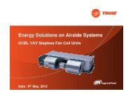
<strong>Installation</strong><strong>Operation</strong><strong>Maintenance</strong>Indoor liquid chiller with integratedhydraulic moduleWater-cooled: CGWN 205 - 206 - 207 -208 - 209 - 210 - 211Condenserless: CCUN 205 - 206 - 207 -208 - 209 - 210 - 211CG-SVX06A-E4
General informationForewordThese instructions are given as aguide to good practice in theinstallation, start-up, operation, andmaintenance by the user, of TraneCGWN/CCUN chillers. They do notcontain full service proceduresnecessary for the continuedsuccessful operation of thisequipment. The services of aqualified technician should beemployed through the medium of amaintenance contract with areputable service company.WarrantyWarranty is based on the generalterms and conditions of themanufacturer. The warranty is voidif the equipment is repaired ormodified without the writtenapproval of the manufacturer, if theoperating limits are exceeded or ifthe control system or the electricalwiring is modified. Damage due tomisuse, lack of maintenance orfailure to comply with themanufacturer's instructions orrecommendations is not covered bythe warranty obligation. If the userdoes not conform to the rules ofthis manual, it may entailcancellation of warranty andliabilities by the manufacturer.ReceptionOn arrival, inspect the unit beforesigning the delivery note.Reception in France only:In case of visible damage: Theconsignee (or the siterepresentative) must specify anydamage on the delivery note,legibly sign and date the deliverynote, and the truck driver mustcountersign it. The consignee (orthe site representative) must notifyTrane Epinal <strong>Operation</strong>s - Claimsteam and send a copy of thedelivery note. The customer (or thesite representative) should send aregistered letter to the last carrierwithin 3 days of delivery.Reception in all countriesexcept France:In case of concealed damage: Theconsignee (or the siterepresentative) must send aregistered letter to the last carrierwithin 7 days of delivery, claimingfor the described damage. A copyof this letter must be sent to TraneEpinal <strong>Operation</strong>s - Claims team.Note: for deliveries in France, evenconcealed damage must be lookedfor at delivery and immediatelytreated as visible damage.About this manualWarnings and cautions appear atappropriate places in thisinstruction manual. Your personalsafety and the proper operation ofthis machine require that you followthem carefully. The constructorassumes no liability for installationsor servicing performed byunqualified personnel.About the unitThese CGWN/CCUN units areassembled, pressure tested,dehydrated, charged and run testedbefore shipment. The informationcontained in this manual applies tounits designated CGWN and CCUN.RefrigerantThe refrigerant provided by themanufacturer meets all therequirements of our units. Whenusing recycled or reprocessedrefrigerant, it is advisable to ensureits quality is equivalent to that of anew refrigerant. For this, it isnecessary to have a precise analysismade by a specialized laboratory. Ifthis condition is not respected, themanufacturer warranty could becancelled.2CG-SVX06A-E4
ContentsGeneral informationForeword 2Warranty 2Reception 2About this manual 2About the unit 2Refrigerant 2General data<strong>Installation</strong>Unit nameplate 10<strong>Installation</strong> instructions 10Handling 11Minimal installation water content 14Water treatment 14Water connections 15Refrigerant line connections 20Winter freeze protection 25Electrical connections 26Interconnection between CCUN and Remote Condenser 28General start-upPreparation 31Start-up 32<strong>Installation</strong> checklist 45<strong>Operation</strong>Control and unit operation 46Weekly start up 46Weekend shutdown 46Seasonal shutdown 46Seasonal start-up 46<strong>Maintenance</strong><strong>Maintenance</strong> instructions 47Troubleshooting guide 49Safety recommendations 51<strong>Maintenance</strong> contract 51Training 51CG-SVX06A-E43
General DataTable 2 - Water cooled units : CGWN High Efficiency (HE) - R407CCGWN CGWN CGWN CGWN CGWN CGWN CGWN205 HE 206 HE 207 HE 208 HE 209 HE 210 HE 211 HEEurovent Performances (1)Net Cooling Capacity (kW) 187.4 216.6 243.4 267.8 295.7 326.2 351.7Total Power input (kW) 39.2 44.9 51.4 58.0 64.2 72.7 82.3Evaporator Water pressure drop (kPa) 24 26 28 33 28 34 39Evaporator Head Pressure available (4) (kPa) 190 170 170 160 165 205 190Condenser Water pressure drop (kPa) 26 29 26 30 37 45 52Condenser Head Pressure available (kPa) 180 170 190 180 170 160 140Main Power supply 400/3/50Sound Power Level (4) (dBA) 85 84 86 85 87 87 87Sound Power Level w/ sound attenuation jacket (4) (dBA) 80 79 81 80 81 81 81Units AmpsNominal (3) (A) 139 158 180 201 219 246 268Start-up AmpsStandard Unit (A) 308 345 405 426 449 508 530With soft starter option (A) 229 255 296 317 335 380 402Short circuit unit capacity (kA) 15 15 15 15 15 15 15Max supply cable size (mm²) 95 95 150 150 150 150 150Min supply cable size (mm²) 35 35 50 50 70 70 95CompressorNumber 4TypeScrollModel (15T+15T) (15T+20T) (15T+25T) (20T+25T) (25T+25T) (25T+30T) (30T+30T)Number of speeds 1 1 1 1 1 1 1Number of motors 1 1 1 1 1 1 1Rated Amps (Comp A / Comp B) (3) (A) 32/32 32/40 32/52 40/52 52/52 52/62 62/62Locked rotor Amps (Comp A / Comp B) (A) 198/198 198/225 198/272 225/272 272/272 272/320 320/320Motor RPM (rpm) 2900 2900 2900 2900 2900 2900 2900Power factor (Comp A / Comp B) 0.89/0.89 0.89/0.91 0.89/0.87 0.91/0.87 0.87/0.87 0.87/0.87 0.87/0.87Sump Heater (Comp A / Comp B) (W) 70/70 70/120 70/150 120/150 150/150 150/150 150/150EvaporatorNumber 1TypeBrazed plateModel DV58-138 DV58-154 DV58-170 DV58-170 DV58-214 DV58-214 DV58-214Water volume (total) (l) 29.0 32.4 35.7 35.7 45.0 45.0 45.0Antifreeze Heater (W) noEvaporator Water ConnectionsVictaulicDiameter 3"Max. water-side operating pressure.without hydraulic module (kPa) 1200 1200 1200 1200 1200 1200 1200with hydraulic module (kPa) 400 400 400 400 400 400 400CondenserNumber 1TypeBrazed plateModel DV58-154 DV58-170 DV58-202 DV58-202 DV58-222 DV58-222 DV58-222Water volume (total) (l) 32.4 35.7 42.4 42.4 46.7 46.7 46.7Condenser Water ConnectionsVictaulicDiameter 3"Max. water-side operating pressure.without hydraulic module (kPa) 1200 1200 1200 1200 1200 1200 1200with hydraulic module suction/discharge (kPa) 400/640 400/640 400/640 400/640 400/640 400/640 400/640DimensionsHeight (mm) 1842Length (mm) 2520Width (mm) 880Operating WeightBase Unit (kg) 1320 1470 1540 1630 1730 1800 1870Evap Hydraulic Kit (kg) 1410 1560 1710 1800 1900 1970 2040Evap + Cds Hydraulic Kit (kg) 1480 1630 1810 1900 2000 2070 2140Shipping WeightBase Unit (kg) 1220 1370 1410 1500 1590 1660 1730Evap Hydraulic Kit (kg) 1310 1460 1580 1670 1760 1830 1900Evap + Cds Hydraulic Kit (kg) 1380 1530 1680 1770 1860 1930 2000System DataNumber of refrigerant circuit 2Capacity steps 4 6 6 6 4 6 4Minimum capacity (%) 25 21.4 18.8 22.2 25 22.7 25Refrigerant Charge (2)Circuit A & B (kg) 14 15 17 17 19 19 19Oil Charge (2)Circuit A & B (l) 8.2 8.8 10.4 11.0 12.6 12.6 12.6(1) at Eurovent Conditions (Evap 12°C/7°C - Condenser. 30°C/35°C)(2) per circuit(3) Max rated conditions(4) Dual Pump OptionCG-SVX06A-E45
General DataTable 3 - Water cooled units : CCUN standard - R407CCCUN CCUN CCUN CCUN CCUN CCUN CCUN205 206 207 208 209 210 211Eurovent Performances (1)Net Cooling Capacity (kW) 181.5 196.0 237.5 262.9 291.7 321.0 349.1Total Power input (kW) 40.3 45.7 51.0 57.4 63.0 70.0 78.4Evaporator Water pressure drop (kPa) 55 57 58 55 54 54 55Evaporator Head Pressure available (4) (kPa) 170 150 150 145 140 185 180Main Power supply 400/3/50Sound Power Level (4) (dBA) 85 84 86 85 87 87 87Sound Power Level w/ sound attenuation jacket (4) (dBA) 80 79 81 80 81 81 81Units AmpsNominal (3) (A) 139 158 180 201 219 246 268Start-up AmpsStandard Unit (A) 308 345 405 426 449 508 530With soft starter option (A) 229 255 296 317 335 380 402Short circuit unit capacity (kA) 15 15 15 15 15 15 15Max supply cable size (mm²) 95 95 150 150 150 150 150Min supply cable size (mm²) 35 35 50 50 70 70 95CompressorNumber 4TypeScrollModel (15T+15T) (15T+20T) (15T+25T) (20T+25T) (25T+25T) (25T+30T) (30T+30T)Number of speeds 1 1 1 1 1 1 1Number of motors 1 1 1 1 1 1 1Rated Amps (Comp A / Comp B) (3) (A) 32/32 32/40 32/52 40/52 52/52 52/62 62/62Locked rotor Amps (Comp A / Comp B) (A) 198/198 198/225 198/272 225/272 272/272 272/320 320/320Motor RPM (rpm) 2900 2900 2900 2900 2900 2900 2900Power factor (Comp A / Comp B) 0.89/0.89 0.89/0.91 0.89/0.87 0.91/0.87 0.87/0.87 0.87/0.87 0.87/0.87Sump Heater (Comp A / Comp B) (W) 70/70 70/120 70/150 120/150 150/150 150/150 150/150EvaporatorNumber 1TypeBrazed plateModel DV58-82 DV58-94 DV58-106 DV58-122 DV58-138 DV58-154 DV58-170Water volume (total) (l) 17.2 19.7 22.2 25.6 29.0 32.4 35.7Antifreeze Heater (W) noEvaporator Water ConnectionsVictaulic MaleDiameter 3"Max. water-side operating pressure.without hydraulic module (kPa) 1200 1200 1200 1200 1200 1200 1200with hydraulic module (kPa) 400 400 400 400 400 400 400Remote condenser connectionsDischarge line diameter circuit 1 & 2 1"5/8Liquid line diameter circuit 1 & 2 1"1/8DimensionsHeight (mm) 1842Length (mm) 2520Width (mm) 880Operating WeightBase Unit (kg) 1120 1170 1300 1370 1420 1510 1590Evap Hyd Kit (kg) 1210 1260 1470 1540 1590 1680 1760Shipping WeightBase Unit (kg) 1070 1120 1230 1290 1340 1430 1500Evap Hyd Kit (kg) 1160 1210 1400 1460 1510 1600 1670System DataNumber of refrigerant circuit 2Capacity steps 4 4 4 4 4 4 4Minimum capacity (%) 25 21 18 22 25 23 25Refrigerant Charge (2)Circuit A & B (kg) Holding chargeOil Charge (2)Circuit A & B (l) 8.2 8.8 10.4 11.0 12.6 12.6 12.6(1) at Eurovent Conditions (Evap 12°C/7°C - Condenser. 30°C/35°C)(2) per circuit(3) Max rated conditions.(4) Dual Pump Option6CG-SVX06A-E4
General DataTable 4 - Water cooled units : CCUN High Efficiency (HE) - R407CCCUN CCUN CCUN CCUN CCUN CCUN CCUN205 HE 206 HE 207 HE 208 HE 209 HE 210 HE 211 HEEurovent Performances (1)Net Cooling Capacity (kW) 189.1 218.6 245.5 270.1 298.5 329.6 355.9Total Power input (kW) 39.0 44.5 49.5 55.7 61.4 69.0 77.6Evaporator Water pressure drop (kPa) 24 26 28 34 29 35 40Evaporator Head Pressure available (4) (kPa) 190 170 170 160 165 205 190Main Power supply 400/3/50Sound Power Level (4) (dBA) 85 84 86 85 87 87 87Sound Power Level w/ sound attenuation jacket4) (dBA) 80 79 81 80 81 81 81Units AmpsNominal (3) (A) 139 158 180 201 219 246 268Start-up AmpsStandard Unit (A) 308 345 405 426 449 508 530With soft starter option (A) 229 255 296 317 335 380 402Short circuit unit capacity (kA) 15 15 15 15 15 15 15Max supply cable size (mm²) 95 95 150 150 150 150 150Min supply cable size (mm²) 35 35 50 50 70 70 95CompressorNumber 4TypeScrollModel (15T+15T) (15T+20T) (15T+25T) (20T+25T) (25T+25T) (25T+30T) (30T+30T)Number of speeds 1 1 1 1 1 1 1Number of motors 1 1 1 1 1 1 1Rated Amps (Comp A / Comp B)(3) (A) 32/32 32/40 32/52 40/52 52/52 52/62 62/62Locked rotor Amps (Comp A / Comp B) (A) 198/198 198/225 198/272 225/272 272/272 272/320 320/320Motor RPM (rpm) 2900 2900 2900 2900 2900 2900 2900Power factor (Comp A / Comp B) 0.89/0.89 0.89/0.91 0.89/0.87 0.91/0.87 0.87/0.87 0.87/0.87 0.87/0.87Sump Heater (Comp A / Comp B) (W) 70/70 70/120 70/150 120/150 150/150 150/150 150/150EvaporatorNumber 1TypeBrazed plateModel DV58-138 DV58-154 DV58-170 DV58-170 DV58-214 DV58-214 DV58-214Water volume (total) (l) 29.0 32.4 35.7 35.7 45.0 45.0 45.0Antifreeze Heater (W) noEvaporator Water ConnectionsVictaulicDiameter 3"Max. water-side operating pressure.without hydraulic module (kPa) 1200 1200 1200 1200 1200 1200 1200with hydraulic module (kPa) 400 400 400 400 400 400 400Remote condenser connectionsDischarge line diameter circuit 1 & 2 1"5/8Liquid line diameter circuit 1 & 2 1"1/8DimensionsHeight (mm) 1842Length (mm) 2520Width (mm) 880Operating WeightBase Unit (kg) 1180 1240 1300 1390 1480 1550 1620Evap Hyd Kit (kg) 1270 1330 1470 1560 1650 1720 1790Shipping WeightBase Unit (kg) 1120 1170 1210 1300 1380 1450 1520Evap Hyd Kit (kg) 1210 1260 1380 1470 1550 1620 1690System DataNumber of refrigerant circuit 2Capacity steps 4 4 4 4 4 4 4Minimum capacity (%) 25 21 18 22 25 23 25Refrigerant Charge (2)Circuit A & B (kg) Holding chargeOil Charge (2)Circuit A & B (l) 8.2 8.8 10.4 11.0 12.6 12.6 12.6(1) at Eurovent Conditions (Evap 12°C/7°C - Condenser. 30°C/35°C)(2) per circuit(3) Max rated conditions.(4) Dual Pump OptionCG-SVX06A-E47
General DataTable 5 - Evaporator hydraulic module205 206 207 208 209 210 211High head pressure optionNumber of pump sets 1Motor (1) (2) (kW) 4.0 4.0 5.5 5.5 5.5 7.5 7.5Rated Amps (1) (2) (A) 7.5 7.5 11.1 11.1 11.1 14.7 14.7Motor RPM (rpm) 2900Low head pressure optionNumber of pump sets 1Motor (1) (2) (kW) 2.2 2.2 4.0 4.0 4.0 5.5 5.5Rated Amps (1) (2) (A) 4.4 4.4 7.5 7.5 7.5 11.1 11.1Motor RPM (rpm) 2900Expansion tank volume (l) 25User volume expansion capacity (3) (l) 12000Water strainer diameter 3" 3" 4" 4" 4" 4" 4"Piping(1) Per motor(2) Dual pump option(3) Hydrostatic pressure 3 bar at 45°C with -12°C miniSteelTable 6 - Condenser hydraulic module205 206 207 208 209 210 211High head pressure optionNumber of pump sets2 (in parallel)Motor (1) (2) (kW) 3 3 4 4 4 4 4Rated Amps (1) (2) (A) 6.1 6.1 7.7 7.7 7.7 7.7 7.7Motor RPM (rpm) 2900 2900 2900 2900 2900 2900 2900Low head pressure optionNumber of pump sets2 (in parallel)Motor (1) (2) (kW) 2.2 2.2 3 3 3 3 3Rated Amps (1) (2) (A) 4.2 4.2 6.1 6.1 6.1 6.1 6.1Motor RPM (rpm) 2900Water strainer diameter - low head 3" 3" 4" 4" 4" 4" 4"Water strainer diameter - high head 4" 4" 4" 4" 4" 4" 4"Piping(1) Per motor(2) Dual pump option(3) Hydrostatic pressure 3 bar at 45°C with -12°C miniSteel8CG-SVX06A-E4
General DataTable 7 - RTCA remote condenserRTCA RTCA RTCA RTCA RTCA208 209 211 213 215Nominal heat rejected (1) (3)Standard 169.1 191.2 227.7 341.1 387.4Low noise (LN) 128.7 150.8 179.8 251.5 300Main Power supply400 V / 3 Ph / 50 HzSound Power Level (2 ) (3)Standard (dB(A)) 90 90 92 93 93Low noise (dB(A)) 85 85 87 88 88Condenser coilsNumber of circuits 2 2 2 2 2Number of rows 3 3 4 3 3Tube diameter (inches) 3/8 3/8 3/8 3/8 3/8Fin spacing (fins/foot) 168 168 144 168 168Frontal surface area (m 2 ) 5.7 6.9 6.9 11.3 11.7Condenser volume (l) 41 49 66 82 98Airflow (3)Number of fans 2 x 2 2 x 2 2 x 3 2 x 4 2 x 4Standard (m 3 /h) 54800 70900 84700 109600 119500Low noise (m 3 /h) 42500 50400 69300 77200 84700Fan diameter (mm) 762 762 762 762 762Unit dimensionsLength (mm) 2870 2870 2870 4610 5450Width (mm) 2285 2285 2285 2285 2285Height (mm) 1655 1655 1655 1630 1630Discharge line connection (inches) 1"5/8 1"5/8 1"5/8 2"1/8 2"1/8Liquid line connection (inches) 1"1/8 1"1/8 1"1/8 1"5/8 1"5/8Unit weight (4)Refrigerant operating charge (kg) 2 x 11 2 x 13 2 x 18 2 x 22 2 x 26Operating weight (kg) 810 890 1090 1535 1770(1) At Eurovent conditions : Air inlet temperature = 25°C ; Temperature Difference (Air inlet/Saturated Condensing Temp.) = 15 K(2) In accordance with ISO 3747(3) Nominal fan speed.(4) With aluminium fins.CG-SVX06A-E49
<strong>Installation</strong>Unit nameplateThe unit nameplate gives thecomplete model reference numbers.The unit power rating is shown, andpower supplies should not deviateby more than 5% from the ratedpower. Compressor motoramperage is shown in box I.MAX.The customer's electricalinstallation must be able towithstand this current.<strong>Installation</strong> instructionsFoundationsNo special foundations are required,provided the supporting surface isflat and level, and can withstand theweight or the unit.Isolating rubber pads6 pads are supplied as standardwith the machine (55x150mm).They should be placed between thesupporting floor and the unit toisolate from the ground. Trane doesnot recommend to install springisolators.Water drain holeInstall a drain hole wide enough todrain away water from the unit inthe event of shut-down or repair.ClearanceRespect recommended clearancearound the unit to allowmaintenance operation to take placewithout obstruction. For minimumclearance, consult the certifiedsubmittals, which are available onrequest from your Trane Agency.Note for RTCA remote condenser:When determining unit placement,give careful consideration toensuring a sufficient flow of airacross the condenser heat-transfersurface. The unit must be positionedso that the airflow through thecondensing coils is not hindered byany obstacle. The condensing coilsmust be protected from side windswhen their speed exceeds 16 km/h.• Position the unit above theaverage height of snowobserved in the region where itis installed.• Never install temporary orpermanent objects (tarp or roof)over the unit, because recyclingof hot air would reduce thecapacity of the condensing coils.• Discharged air from the fansmust not be obstructed. It isprohibited to install ducts for thefan discharge air (even shortones). This is because the fanssupplied on standard units donot generate any additionalstatic pressure.10CG-SVX06A-E4
<strong>Installation</strong>HandlingA specific lifting method isrecommended as follows:1. 4 lifting points are built into theunit.2. Slings and spreader bar to beprovided by rigger and attachedto the 4 lifting points.3. Minimum rated lifting capacity(vertical) of each sling andspreader bar shall be no lessthan the tabulated unit shippingweight. Refer to Figures 1 and 2CAUTION: This unit must be liftedwith the outmost care. Avoid shockload by lifting slowly and evenly. Toprevent any damage, position thelifting bar so that the slings do nottouch the unit.Figure 1 - Rigging the unit - CGWN - CCUNABCDCG-SVX06A-E411
<strong>Installation</strong>Figure 2 - Rigging the unit - RTCAACB12CG-SVX06A-E4
<strong>Installation</strong>Table 8 - Dimensions of recommended slings and swing-bar (see Figures 1 and 2)Max Shipping Weight (kg)A (mm) B (mm) C (mm) D (mm) D E FCGWN 2051170 1260 1330CGWN 206 1230 1320 1390CGWN 207 1360 1530 1630CGWN 208 1430 1600 1700CGWN 209 1500 1670 1770CGWN 210 1590 1760 1860CGWN 211 1690 1860 1960CGWN 205 HE 1220 1310 1380CGWN 206 HE 1370 1460 1530CGWN 207 HE 1410 1580 1680CGWN 208 HE 1500 1670 1770CGWN 209 HE 1590 1760 1860CGWN 210 HE 1660 1830 1930CGWN 211 HE 1730 1900 20001100 600 500 2400CCUN 205 1070 1160 -CCUN 206 1120 1210 -CCUN 207 1230 1400 -CCUN 208 1290 1460 -CCUN 209 1340 1510 -CCUN 210 1430 1600 -CCUN 211 1500 1670 -CCUN 205 HE 1120 1210 -CCUN 206 HE 1170 1260 -CCUN 207 HE 1210 1380 -CCUN 208 HE 1300 1470 -CCUN 209 HE 1380 1550 -CCUN 210 HE 1450 1620 -CCUN 211 HE 1520 1690 -RTCA 208 STD/LN810 - -RTCA 209 STD/LN 2240 1700 1700 -890 - -RTCA 211 STD/LN 1090 - -RTCA 213 STD/LN1535 - -2240 2800 2800 -RTCA 215 STD/LN 1770 - -D = Base unit (without hydraulic module)E = Base unit + evaporator hydraulic moduleF = Base unit + evaporator and condenser hydraulic modulesCG-SVX06A-E413
<strong>Installation</strong>Minimal installation watercontentThe water volume is an importantparameter because it allows astable chilled water temperatureand avoids short cycle operation ofthe compressors.Parameters which influence thewater temperature stability• Water loop volume• Load fluctuation• Number of capacity steps• Compressors rotation• Dead band• Minimum time between 2 startsof a compressorTable 9 gives the minimalinstallation water contentrecommended according to allthese parameters for both comfortand process cooling application.Water treatmentUntreated or insufficiently treatedwater, if used in this unit, maycause scale, slime or algae toaccumulate or cause erosion andcorrosion. As Trane does not knowthe components used in thehydraulic network and the quality ofthe water used, we recommend theservices of a qualified watertreatment specialist. The followingmaterials are used in Trane chillersheat exchangers:• Stainless steel plates AISI 316,1.4401 with copper brazing• Water piping: steel• Water connections: brassTrane will not accept any liability inregards of damage due to the useof untreated or improperly treatedwater or from the use of saline orbrackish water. If water treatment isrequired, contact your local Tranesales office.Table 9 - Minimal water contentProcess cooling ApplicationComfortApplication (1)4°C Dead band(2)3°C Dead band(3)CGWN - CCUN 205 300 l 1100 l 1700 lCGWN - CCUN 206 400 l 1500 l 2600 lCGWN - CCUN 207 500 l 1900 l 3500 lCGWN - CCUN 208 500 l 1800 l 3000 lCGWN - CCUN 209 500 l 1700 l 2700 lCGWN - CCUN 210 600 l 2100 l 3600 lCGWN - CCUN 211 600 l 2000 l 3300 l(1) Minimum water loop volume in order to prevent excessive compressor cycling(2) Minimum water loop volume to obtain maximum +/- 2°C chilled water temperature fluctuation vs. chilledwater set-point(3) Minimum water loop volume to obtain maximum +/- 1,5°C chilled water temperature fluctuation vs. chilledwater set-point14CG-SVX06A-E4
<strong>Installation</strong>Water connectionsBefore making any connections,make sure the labeling for enteringand leaving water corresponds tothe submittals. CGWN water-cooledchillers and CCUN condenserlessunits are available in severalversions:1) Evaporator side options• No hydraulic control• With pump contactors to controla remote pump (single or dual)• With pump integrated hydraulicmodule, single or dual pump,low or high pressure head2) Condenser side options• No hydraulic control• With pump contactors to controla remote pump (single or dual)• With pump integrated hydraulicmodule, consisting of two singlepumps in parallel to adjustcondenser waterflow as afunction of unit capacity, low orhigh pressure headTypical water circuits are given inFigures 3 to 6.Figure 3 - CGWN hydraulic flow chart - without hydraulic module1 2 33CW2433HW5 41. Insulated evaporator2. Valve for air vent3. ¼ SAE Male pressure tab4. ¼ SAE Male drain tab5. Condenser6. Water strainer7. Expansion Tank8. Pressure relief valve9. Single or double evaporator pump10. Drain pan11. Condenser pump12. Check valveCW: Chilled water loopHW: Condensation water loopTT: Temperature sensorPi: Pressure gaugeFT: Water flow switchA: For sizes 205 to 207 standard head 3"B: For sizes 208 to 211 and all sizes high 4"CG-SVX06A-E415
<strong>Installation</strong>Figure 4 - CCUN hydraulic flow chart - without hydraulic module1 2 33CW41. Insulated evaporator2. Valve for air vent3. ¼ SAE Male pressure tab4. ¼ SAE Male drain tab5. Condenser6. Water strainer7. Expansion Tank8. Pressure relief valve9. Single or double evaporator pump10. Drain pan11. Condenser pump12. Check valveCW: Chilled water loopHW: Condensation water loopTT: Temperature sensorPi: Pressure gaugeFT: Water flow switchA: For sizes 205 to 207 standard head 3"B: For sizes 208 to 211 and all sizes high 4"16CG-SVX06A-E4
<strong>Installation</strong>Figure 5 - CGWN hydraulic flow chart - with hydraulic module on both evaporatorand condenser sides7 86239 1034CW124363HW111254412111. Insulated evaporator2. Valve for air vent3. ¼ SAE Male pressure tab4. ¼ SAE Male drain tab5. Condenser6. Water strainer7. Expansion Tank8. Pressure relief valve9. Single or double evaporator pump10. Drain pan11. Condenser pump12. Check valveCW: Chilled water loopHW: Condensation water loopTT: Temperature sensorPi: Pressure gaugeFT: Water flow switchA: For sizes 205 to 207 standard head 3"B: For sizes 208 to 211 and all sizes high 4"CG-SVX06A-E417
<strong>Installation</strong>Figure 6 - CCUN hydraulic flow chart - with hydraulic module on evaporator side only7 82 369 1034CW141. Insulated evaporator2. Valve for air vent3. ¼ SAE Male pressure tab4. ¼ SAE Male drain tab5. Condenser6. Water strainer7. Expansion Tank8. Pressure relief valve9. Single or double evaporator pump10. Drain pan11. Condenser pump12. Check valveCW: Chilled water loopHW: Condensation water loopTT: Temperature sensorPi: Pressure gaugeFT: Water flow switchA: For sizes 205 to 207 standard head 3"B: For sizes 208 to 211 and all sizes high 4"18CG-SVX06A-E4
<strong>Installation</strong>Warning: Units with hydraulicmodule contain all safety andoperation devices and only requirethe supply and return piping withisolating valves for maintenance ofwater strainer and pump seal ring.The unit water piping shall beconnected using expansioncompensators (see Figure 7). Unitswithout hydraulic module have tobe connected according to Figure 8.Figure 7 - Connection of units with hydraulic module - Evaporator and condensersides127356489Figure 8 - Connection of units without hydraulic module - Evaporator and condensersides645CG-SVX06A-E419
<strong>Installation</strong>1. Pressure gauges: show enteringand leaving water pressure(2 pressure ports are availableinside of the unit - see item 1 inFigure 7)2. Balancing valve: adjusts waterflow.3. Air purge : allows removal of airfrom the water circuit during fillup.4. Stop valves: isolate chillers andwater circuiting pump duringmaintenance operations.5. Thermometers: indicate chilledwater entering and leavingtemperatures.6. Expansion compensators: avoidmechanical stress betweenchiller and piping installation.7. Stop valve located on the outletconnection: used to measure thewater pressure inlet or outlet ofevaporator.8. Strainer: avoid to get heatexchangers dirty.Important : installation must beequipped with efficient strainer inorder that only clean water entersinto exchanger. If there is nostrainer, reserve will be formulatedby the Trane technician at the startupof the unit. The strainer usedmust be able to stop all particleswith a diameter greater than0.8 mm.9. Draining: used as the drainingthe plate heat exchanger.To protect the environment, it iscompulsory to recover and processglycol brines.Refrigerant lineconnectionsPipingMaximum distances and refrigerantline diameters between units mustbe checked according to theconfiguration and system operatingconditions (Chilled watertemperature and subcooling).Tables 10-12 provide the maximumacceptable height according tosubcooling available andrecommended diameters fordischarge liquid lines when CCUNcondenserless chillers areconnected to Trane RTCA remotecondensers.Figure 9 - <strong>Installation</strong> configuration - CCUN and RTCA at the same levelRTCACCUN121: Discharge line2: Liquid line20CG-SVX06A-E4
<strong>Installation</strong>Figure 10 - <strong>Installation</strong> configuration - CCUN below RTCARTCA12CCUN1: Discharge line2: Liquid lineFigure 11 - <strong>Installation</strong> configuration - CCUN above RTCACCUN21RTCAH1: Discharge line2: Liquid lineCG-SVX06A-E421
<strong>Installation</strong>The minimum required subcoolingat the remote condenser level wheninstalled below is defined in thefollowing table.Example : If the remote condenseris 10m below the CCUN and thecondensing temperature is 50°C, therefrigerant subcooling leaving theremote condenser shall not bebelow 4°C. To increase the amountof subcooling, more refrigerantcharge is required.Table 10 - Maximum elevation (H) of CCUN above RTCASubcooling°CCondensing dew temperature °C20°C 35°C 50°C 65°C4°C 4 m 6 m 8 m 10 m6°C 8 m 12 m 16 m 20 m8°C 12 m 17 m 23 m 30 m10°C 16 m 23 m 30 m 40 m12°C 20 m 28 m 38 m 49 mTable 11 - Recommended discharge line diameters for vertical risersUnit sizeLeaving chilled water temperature (°C)-12 -10 -8 -6 -4 -2 0 2 4 6 8 10 12 14CCUN 205 7/8" 1"1/8 1"3/8CCUN 206 7/8" 1"1/8 1"3/8 1"5/8CCUN 207 1"1/8 1"3/8 1"5/8CCUN 208 1"1/8 1"3/8 1"5/8CCUN 209 1"1/8 1"3/8 1"5/8CCUN 210 1"1/8 1"3/8 1"5/8CCUN 211 1"1/8 1"3/8 1"5/8Table 12 - Recommended liquid line diameters (either horizontal or vertical)Unit sizeLeaving chilled water temperature (°C)-12 -10 -8 -6 -4 -2 0 2 4 6 8 10 12 14CCUN 205 7/8" 1"1/8CCUN 206 7/8" 1"1/8CCUN 207 7/8" 1"1/8 1"3/8CCUN 208 7/8" 1"1/8 1"3/8CCUN 209 7/8" 1"1/8 1"3/8CCUN 210 1"1/8 1"3/8 1"5/8CCUN 211 1"1/8 1"3/8 1"5/822CG-SVX06A-E4
<strong>Installation</strong>InsulationInsulate refrigerant lines frombuilding itself to avoid transmissionto building structure of vibrationsnormally caused by pipework. Alsoavoid bypassing the unit's dampingsystem by fixing the refrigerantlines or the electrical ducts veryrigidly. Vibrations may propagateinto building structure throughrigidly fixed refrigerant lines.Pressure tests and leak detectionWarning : During operations, takethe following precaution:1. Neither oxygen nor acethyleneshould be used instead ofrefrigerant and nitrogen to detectleaks, otherwise a violentexplosion may occur.2. Always use valves andmanometers to check the testpressure in system. Excessivepressure may either cause pipesto rupture, damage unit, orcause an explosion, causingpossible physical injury. Carryout liquid line and hot gaspressure tests in accordancewith current standards.CAUTION: Do not go more than0.7 bar above the high pressureswitch setpoint. Introduce enoughrefrigerant into circuit for 85 to100 kPa pressure, pump-injectingdry nitrogen, and raise pressure to100 kPa. Search possible leaks usingdetector. This operation should becarried out great care throughoutthe system. If leaks are detected,reduce system pressure, and repairdefective component. Repeat testprocess, to check that the repair canwithstand rated pressure.Refrigerant chargeCCUN unit is delivered with arefrigerant holding charge andisolating valves. After systempressure and vacuum testing, fill upunit with refrigerant as indicated inTables 1-4. The refrigerantcomplement will be chargedaccording to the diameter and thelength of the refrigerant piping workup to obtain the correct subcoolingtemperature:∆t subcooling = 5°C for a liquidtemperature of 40°C.Oil charge - CCUNAbove 60 kg of refrigerant chargeper circuit, special care to the oillevel on compressor is required.The operating oil level shall remainabove half of the oil sight glass. SeeTable 1-4 for oil charges. The oillevel can only be evaluated after10 minutes OFF time of bothcompressors of the circuit. SeeFigure 18.Note: The oil quantity necessary forthe split system has also to beadjusted according to the diameterand the length of the refrigerantpiping work.CAUTION: Use exclusively POE oilrecommended by TRANEImportant note:These operations have to beperformed by a specialist. Theresults have to be written on a startup record by the Trane engineer orthe client's specialist who hasperformed this start up. The quantityof refrigerant and oil added are atthe client's charges.CG-SVX06A-E423
<strong>Installation</strong>Pressure relief valve - CCUNAbove the maximum systemrefrigerant charge, it isrecommended to install a pressurerelief valve. See Figure 12 forinstallation. Depending upon theliquid line diameter selected inTable 12, find the predictedmaximum liquid line length ofinstallation without pressure reliefvalve installed. The recommendedpressure relief valve setting is21 Bar and shall be installed on thelow pressure side of the refrigerantcircuit.Table 13 - Recommended liquid line diameters with pressure relief valve - CCUNUnit size205206207208209210211UnitefficiencymodelMaximumsystemrefrigerantchargewithoutpressurerelief valve(kg)Liquid linediameterMaximumlengthwithoutpressurerelief valve(m)Liquid linediameterMaximumlengthwithoutpressurerelief valve(m)Standard 48 1"1/8 51 7/8" 80High 53 1" 1/8 60 7/8" 94Standard 54 1" 1/8 56 7/8" 88High 59 1" 1/8 65 7/8" 103Standard 61 1"3/8 40 1"1/8 63High 67 1"3/8 47 1"1/8 73Standard 68 1"3/8 44 1"1/8 68High 72 1"3/8 48 1"1/8 75Standard 75 1"3/8 49 1"1/8 49High 82 1"3/8 56 1"1/8 56Standard 75 1" 5/8 31 1"3/8 44High 80 1" 5/8 35 1"3/8 49Standard 74 1" 5/8 27 1"3/8 38High 77 1" 5/8 30 1"3/8 42Figure 12 - Installing pressure relief valve1 = Connection for pressure relief valve circuit 12 = Connection for pressure relief valve circuit 224CG-SVX06A-E4
<strong>Installation</strong>Winter freeze protectionDuring negative ambient airtemperature chilled water pipingmust be fully insulated. Ensure thatall safeties are taken to preventfrost damage during negativeambient air temperature. Thefollowing systems can be used:• Electrical heater mounted on allwater piping exposed tonegative temperatures.• Start chilled water pump duringnegative ambient airtemperature.• Add ethylene glycol in the chilledwater.• Drain water-circuit, however beaware of corrosion process whendrained.CAUTION: There is a risk of freezeupof the evaporator circuit due tointernal refrigerant migration if thecondenser circuit is maintained at alow temperature (below 0°C) for along period during the cold season.If necessary, provide isolationvalves on the condenser watercircuit (CGWN). CCUN is protectedagainst refrigeration migration by aliquid solenoid valve.Figure 13 - Freezing point versus ethylene glycol percentage0-1 0Brine temperature (°C)-2 0-3 0321-4 0-5 00 1 0 2 0 3 0 4 0 5 0 6 01. Liquid2. Freezing without burst effect3. Freezing with burst effect% Ethylene glycolCG-SVX06A-E425
<strong>Installation</strong>When ordered, the outdoor airsensor electronics is factorymountedand wired. It is locatedinside the unit casing near thepressure transducers. The IPC bus isfactory-wired also.The sensing bulb is to be field wiredexternally with the sensor leadsextended back to the control panel.These wires can be spliced with two0.75 to 1.5 mm² HO5 WWF type orsimilar wires, with a maximumlength of 305 meters. Splice atsensor end must be water tight.Figure 15 - CGWN and CCUN main power supply connectionFigure 16 - Outdoor ambient air sensor connectionCG-SVX06A-E427
<strong>Installation</strong>Interconnectionbetween CCUN andRemote CondenserThe CCUN has the capability tocontrol the fan staging of theremote condenser if the option istaken.Each refrigerant circuit can controlfrom one up to 6 fans per circuitusing a 4 output relays(10A/250VAC/AC1/SPDT) card optionprovided in the control box the ofCCUN. The external wiring to theremote condenser shall beconnected directly to the terminalblock for the optional fan relaycards.CAUTION:Power supply to the outdoor fanrelays shall not be provided fromthe CCUN unless special care to theVoltage and to the powerconsumption was evaluated.Table 14 - Control output relaysOutput relayQuantity of fansLow SpeedFan 1High SpeedFan 2 Fan 3 Fan 4 Fan 5 Fan 6Single speedFan option234561 2 3&4 Two fan speed first fan1 3&4 Single speed only fans1 2 3 4 Two fan speed first fan1 3 4 Single speed only fans1 2 3 4 4 Two fan speed first fan1 3 4 4 Single speed only fans1 2 3 3 4 4 Two fan speed first fan1 3 3 4 4 Single speed only fans1 2 3 3 4 4 4 Two fan speed first fan1 3 3 4 4 4 Single speed only fansTable 15 - Fan staging - Example : 4 fans per circuit, single speedStageNumber of FansStandard - 4 fans per circuitRelays Energized1 2 3 4Capacity [%]0 0 0 0 0 0 0.001 1 1 0 0 0 25.002 2 1 0 1 0 50.003 3 0 0 1 1 75.004 4 1 0 1 1 100.00Table 16 - Fan staging - Example : 4 fans per circuit with first fan 2-speedStageNumber of FansLow Ambient 2 Speed 4 fans per circuitRelays Energized1 2 3 4Capacity [%]0 0 0 0 0 0 0.001 0.5 1 0 0 0 12.502 1 0 0 1 0 25.003 1.5 1 0 1 0 37.504 2 0 0 0 1 50.005 2.5 1 0 0 1 62.506 3 0 0 1 1 75.007 3.5 1 0 1 1 87.508 4 0 1 1 1 100.0028CG-SVX06A-E4
<strong>Installation</strong>Operating rangeCAUTION: Maximum operating timefor low condensing water outlet is1 minute. The compressor shallbecome noisy.The envelope represents theoperating range in which the unitwill work without control limitation.To keep the unit operating in thisenvelope, be careful to adjustsetpoints inside with a clearanceequal to half the dead band. Checkalso compressor suction superheatfor being close to 5 or 6°C for lowchilled leaving water temperature tominimize compressor dischargetemperature. For very high leavingcondensing water temperatureabove 55°C, the refrigerant chargecan be minimized by 20%.Figure 17 - CGWN operating limitsCLWT : Condenser Leaving Water TemperatureELWT : Evaporator Leaving Water TemperatureCG-SVX06A-E429
General Start-upPreparationCarry out all operations on check listso that the unit is correctly installedand ready to operate. The installermust check all the following pointsbefore calling in the Trane ServicingDepartment to put the equipmentinto service:• Check position of unit• Check unit is level• Check type and position ofrubber pads• Check clearance required formaintenance (Refer to certifieddrawings)• Check clearance aroundcondenser access if splitinstallation (CCUN + RTCA -Refer to certified drawings)• Chilled water circuit ready tooperate, filled with water,pressure test carried out and airpurged• Chilled water circuit must berinsed• Check the presence of waterstrainer ahead of evaporator• The strainers must be cleanedafter 2 hours of pumps operation• Check the thermometers andmanometers position• Check chilled water pumpsinterconnection to control panel• Ensure that the isolationresistance of all power supplyterminals to ground complieswith standards and regulationsin force• Check that unit voltage andfrequency supplied match ratedinput voltage and frequency• Check that all electricalconnections are clean and sound• Check that main power supplyswitch is sound• Check Ethylene glycol orPropylene glycol % in the chilledwater circuit• Water flow control checking:decrease the water flow andcheck the electrical contact in thecontrol panel• Check chilled water pressuredrop through evaporator (unitwithout hydraulic module) orunit available pressure (unit withhydraulic module) are inaccordance with the Trane orderwrite-up (See Figures 19-34).• On start-up of each motor in thesystem, check the direction ofrotation and operation of all thecomponents they drive• Check that there is sufficientdemand for cooling on the dayof start-up (around 50% ofnominal load)CG-SVX06A-E431
General Start-upStart-upFollow the instructions below tocorrectly start-up the unit.<strong>Installation</strong> and chiller inspection• Ensure that all the operationsabove (start-up preparation), arefollowed.• Follow the instruction stuckinside the electrical cabinet:• Put the plexiglass supplied byTrane in front of the powerterminal.• Ensure all water and refrigerantvalves are in service positions• Ensure that the unit is notdamaged• Ensure that sensors are properlyinstalled in their bulb-wells andsubmerged in heat conductingproduct• Check fixing of capillary tubes(protection from vibration andfrom wear) and ensure that theyare not damaged• Reset all manually set controldevices,• Check refrigerating circuitstightnessChecking and settingCompressors:• Check oil level at rest. The levelshould reach at least theminimum oil level on theindicator located on oilequalization line when thecompressors are OFF for apackaged unit (CGWN) and after10 minutes OFF time for a splitunit (CCUN with remotecondenser). See Figure 19 forcorrect level.• Check fixing of capillary tubes(protection from vibration andfrom wear) and ensure that theyare not damaged• Reset all manually set controldevices• Check refrigerating circuitstightness• Check electrical terminalstightening of the motors and inthe control panel• Check the isolation of themotors, using a 500V DCmegohmeter which meetsmanufacturer's specifications(minimum value 2 megohms)• Check the direction of therotation using phasemeterElectrical power wiring:• Check all the electrical terminalsare tight• Set-up compressors overloadrelays• Set-up fan-motors overloadrelaysElectrical control wiring:• Check all the electrical terminalsare tight• Check all the pressostats• Check and set-up the TRACERCH530 control module• Test and start-up without theelectrical powerCondenser:• Check setting of the safetypressure valve• Check the insulation of themotors using a 500V DCmegohmeter which meetsmanufacturer's specifications(minimum value 2 megohms)Figure 19 - Compressor oil level at oilequalization line121. Max. oil level2. Min. oil level32CG-SVX06A-E4
General Start-upOperating parameters statement• Switch on main power supplyswitch• Start the water pump(s) andcheck there is no cavitation• Start-up the unit followingprocedure described in manualref CG-SVU02A The unit and thechilled water pumps contactormust be connected together.After unit start up, leave inoperation for at least 15 minutes, toensure pressures are stabilized.Then check:• voltage• compressors currents• leaving and return chilled watertemperature• suction temperature andpressure• ambient air temperature• blowing air temperature• discharge pressure andtemperature• liquid refrigerant temperatureand pressureOperating parameters:• chilled water pressure dropthrough evaporator (if nohydraulic module is installed) orunit available pressure. It mustbe in accordance with Traneorder write-up.• superheat: difference betweensuction temperature and dewpoint temperature. Normalsuperheat should be within 4and 7 °C with R407C.• sub-cooling: difference betweenliquid temperature and bubblepoint temperature. Normalsubcooling should be within2 and 10°C with R407C.• Condenser approach: differencebetween dew point temperaturein high pressure and condenserair inlet temperature. Normalvalue on standard unit withR407C, should be 15 to 23°C atfull load.• Evaporator approach: differencebetween outlet watertemperature and dew pointtemperature in low pressure.Normal value on standard unit,without Ethylene glycol in chilledwater, should be about + 2-3°C.Final checkWhen the unit is operatingcorrectly:• Check that the unit is clean andclear of any debris, tools, etc.• Ensure all valves are in operatingposition.• Close control and starter paneldoors and check panels fixation.CG-SVX06A-E433
General Start-upCAUTION:For the warranty to apply, any startupcarried out directly by thecustomer must be recorded in adetailed report, which must be sentas soon as possible to your localTrane office.• Do not start-up a motor whoseinsulation resistance is less than2 megohms• Phase imbalance should not begreater than 2%.• The voltage supplied to motorsshould be within 5% of the ratedvoltage on the compressornameplate.• Excessive emulsion of the oil inthe compressor shows thatrefrigerant is present in the oiland the result will be thatcompressor is not lubricatedenough. Shut down compressorand wait for 60 minutes for thesump heaters to heat oil andstart again. Should this not work,consult Trane technician.• Excess oil in compressor candamage the compressor. Beforeadding oil, consult Tranetechnician. Use only productsrecommended by Trane.• The compressors must operatein a single direction of rotation. Ifrefrigerant high pressureremains stable in the 30 secondsafter compressor start-up,immediately shut down unit andcheck the direction of rotationusing phasemeter.Warning :The chilled water circuit may beunder pressure. Bring down thispressure before opening up thesystem to rinse out or fill up thewater circuit. Failure to comply withthis instruction may causeaccidental injury to maintenancepersonnel. If a cleaning solution isused in the chilled water circuit, thechiller must be isolated from thewater circuit to avoid all thedamage risks of the chiller andevaporator water pipes.Figure 20 - Standard units evaporator pressure drop10050EWPD (kPa)1051 2 3 4 5 6 71 - CGWN-CCUN 2052 - CGWN-CCUN 2063 - CGWN-CCUN 2074 - CGWN-CCUN 2085 - CGWN-CCUN 2096 - CGWN-CCUN 2107 - CGWN-CCUN 21111 5 10 50100EWFR : Evaporator Waterflow RateEWPD : Evaporator Water Pressure DropEWFR (l/s)34CG-SVX06A-E4
General Start-upFigure 21 - High efficiency units (HE) evaporator pressure drop10050EWPD (kPa)1051 2 3 41 - CGWN-CCUN 205 HE2 - CGWN-CCUN 206 HE3 - CGWN-CCUN 207-208 HE4 - CGWN-CCUN 209-210-211 HE11 5 10 50100EWFR : Evaporator Waterflow RateEWPD : Evaporator Water Pressure DropEWFR (l/s)Figure 22 - Standard units condenser pressure drop10050CWPD (kPa)1051 2 3 4 5 61 - CGWN-CCUN 205-2062 - CGWN-CCUN 2073 - CGWN-CCUN 2084 - CGWN-CCUN 2095 - CGWN-CCUN 2106 - CGWN-CCUN 21111 5 10 50100CWFR : Condenser Waterflow RateCWPD : Condenser Water Pressure DropCWFR (l/s)CG-SVX06A-E435
General Start-upFigure 23 - High efficiency units (HE) condenser pressure drop10050CWPD (kPa)1051 2 3 41 - CGWN-CCUN 205 HE2 - CGWN-CCUN 206 HE3 - CGWN-CCUN 207-208 HE4 - CGWN-CCUN 209-210-211 HE11 5 10 50100CWFR : Condenser Waterflow RateCWPD : Condenser Water Pressure DropCWFR (l/s)Figure 24 - Evaporator available pressure - Standard units - Low head pressure -Single pump250200150kPa100500207205 206208 210 2112090 5 10 15 20 25EWFR (l/s)EWFR : Evaporator Waterflow Rate36CG-SVX06A-E4
General Start-upFigure 25 - Evaporator available pressure - Standard units - Low head pressure - Dualpump250200150EWFR : Evaporator Waterflow RateFigure 26 - Evaporator available pressure - Standard units - High head pressure -Single pumpkPakPa100500205 2062070 5 10 15 20 25EWFR (l/s)208 209210 211250200150100500205210211206207208 2090 5 10 15 20 25 27EWFR (l/s)EWFR : Evaporator Waterflow RateCG-SVX06A-E437
General Start-upFigure 27 - Evaporator available pressure - Standard units - High head pressure - Dualpump250200150209205210 211206 2072080 5 10 15 20 25 27EWFR (l/s)EWFR : Evaporator Waterflow RateFigure 28 - Evaporator available pressure - High efficiency units - Low head pressure -Single pump250200150kPakPa10050010050206 HE207 HE211 HE0205 HE208 HE 209 HE 210 HE0 5 10 15 20 25 27EWFR (l/s)EWFR : Evaporator Waterflow Rate38CG-SVX06A-E4
General Start-upFigure 29 - Evaporator available pressure - High efficiency units - Low head pressure -Dual pump250200150EWFR : Evaporator Waterflow RateFigure 30 - Evaporator available pressure - High efficiency units - High head pressure -Single pumpkPakPa10050205 HE207 HE211 HE0206 HE208 HE 209 HE 210 HE0 5 10 15 20 25 27EWFR (l/s)250200150100207 HE208 HE 209 HE210 HE211 HE50205 HE206 HE00 5 10 15 20 25 27EWFR (l/s)EWFR : Evaporator Waterflow RateCG-SVX06A-E439
General Start-upFigure 31 - Evaporator available pressure - High efficiency units - High head pressure -Dual pump250200150EWFR : Evaporator Waterflow RateFigure 32 - Condenser available pressure - Standard units - Low head pressure250200150kPakPa10050207 HE210 HE208 HE 209 HE211 HE0205 HE 206 HE0 5 10 15 20 25 27EWFR (l/s)100502110205208210206207 2090 5 10 15 20 25CWFR (l/s)CWFR : Condenser Waterflow Rate40CG-SVX06A-E4
General Start-upFigure 33 - Condenser available pressure - Standard units - High head pressure250200150CWFR : Condenser Waterflow RateFigure 34 - Condenser available pressure - High efficiency units - Low head pressure250200150kPakPa100500206205207210 211208 2090 5 10 15 20 25CWFR (l/s)100500207208 209 - 210 - 211205 2060 5 10 15 20 25CWFR (l/s)CWFR : Condenser Waterflow RateCG-SVX06A-E441
General Start-upFigure 35 - Condenser available pressure - High efficiency units - High head pressure250200150kPa10050205 HE206 HE207 HE208 HE209 HE210 HE211 HE00 5 10 15 20 25CWFR (l/s)CWFR : Condenser Waterflow RateWhen ethylene glycol is added in the chilled water circuit the followingadjustment factors have to be taken in account.Figure 36 - Ethylene Glycol recommended concentration40%Ethylene Glycol recommended concentration35%30%25%20%15%10%5%0%-12 °C -10 °C -8 °C -6 °C -4 °C -2 °C 0 °C 2 °C 4 °CLowest water temperature42CG-SVX06A-E4
General Start-upFigure 37 - Propylene Glycol recommended concentration45%Propylene Glycol Glycol recommended concentration concentration40%35%30%25%20%15%10%5%0%-10 °C -8 °C -6 °C -4 °C -2 °C 0 °C 2 °C 4 °CLowest water water temperatureTable 17 - Correction factors to apply when glycol is used in water loopsFluid TypeGlycol ConcentrationEvaporator CondenserPerformanceF-CC F-PIEvaporatorF-FLEVP F-PDEVPCondenserF-FLCDS F-PDCDSWater only 0% 0% 1.00 1.00 1.00 1.00 1.00 1.00Ethylene GlycolMono-Propylene Glycol10% 0% 0.99 1.00 1.02 1.02 1.00 1.0020% 0% 0.98 1.00 1.05 1.06 1.00 1.0030% 0% 0.97 1.00 1.10 1.10 1.00 1.000% 10% 1.00 1.00 1.00 1.00 1.02 1.050% 20% 1.00 1.01 1.00 1.00 1.04 1.090% 30% 1.00 1.02 1.00 1.00 1.08 1.1410% 0% 0.99 1.00 1.01 1.05 1.00 1.0120% 0% 0.97 1.00 1.03 1.10 1.00 1.0030% 0% 0.96 1.00 1.05 1.17 1.00 1.010% 10% 1.00 1.01 1.00 1.00 1.01 1.060% 20% 1.00 1.01 1.00 1.00 1.02 1.130% 30% 0.99 1.02 1.00 1.00 1.05 1.21CG-SVX06A-E443
General Start-upThe correction factors found inTable 16 can be applied as follows:1. Cooling capacity with glycol[kW] = F-CC x Cooling capacitywater [kW] (found in Tables 1-4)2. Power Input with glycol [kW] =F-PI x Power Input water [kW](found in Tables 1-4)3. Water Flow Evaporator withglycol [Litres/sec] = F-FLEVP xCooling capacity with glycol [kW]x 0.239 x (1 / Delta T Evaporator[°C])4. Water Pressure drop Evaporatorwith glycol [kPa] = F-PDEVP xWater Pressure drop Evaporatorwater [kPa] (found in Figures20 and 21)CGWN Only:5. Water Flow Condenser withglycol [Litres/sec] = F-FLCDS x(Cooling capacity with glycol[kW] + Power input with glycol[kW]) x 0.239 x (1 / Delta TCondenser [°C])6. Water Pressure drop Condenserwith glycol [kPa] = F-PDCDS xWater Pressure drop Condenserwater [kPa] (found in Figures22 and 23)In case of application with negativetemperature at the evaporator,combination of simultaneous usageof glycol both in evaporator andcondenser, or usage of another typeof fluid: please contact your localTrane sales representative. A reliefvalve is located at pump suctionlimiting water circuit pressure at3 bar. Nitrogen pressure inside ofthe expansion tank must be equal tothe geometric height of theinstallation + 0.5 bar (in order toavoid air entering in the watercircuit) Expansion tank must beinflated with nitrogen. Pressuremust be checked yearly. For a goodpump operation, pump suctionpressure must be between 0.5 and2.5 bar when pump runs.44CG-SVX06A-E4
General Start-up<strong>Installation</strong> checklistThis list must be checked off by the installer to ensure correct installation before the unit start up.UNIT POSITIONCheck clearance around condenserCheck clearance required for maintenance accessCheck type and position of rubbers padsCheck unit is levelCHILLED WATER CIRCUITCheck thermometers and manometers presence and positionCheck water flow rate balancing valve presence and positionCheck presence of strainer ahead of evaporatorCheck presence of air-purge valveCheck rinsing and filling of chilled water pipesCheck water pump(s) contactor interconnected to control panelCheck water flowCheck chilled water pressure drop or unit available pressure (units with hydraulic module)Check for leaks in chilled water pipesELECTRICAL EQUIPMENTCheck installation and rating of mains power switch/fusesCheck electrical connections complied with specificationCheck that electrical connections are in accordance with information on manufacturer's identification plateCheck direction of rotation using phasemeterComments……………………………………………………………………………………………………………………………………………………………………………………………………………………………………………………………………………………………………………………………………………………………………………………………………………………………………………………………………………………………………………………………………………………………………………………………………………………………………………………………………………………………………………………………………………………………Signature:…………………………………………………………………….Name:…………………………………...…………………Order N°: ……………………………………………………………………………………………………………………………………Work site: ……………………………………………………………………………………………………………………………………Please return to your local Trane Service OfficeCG-SVX06A-E445
<strong>Operation</strong>Control and unit operationThe control is through theTRACER CH530 control module.• Check the chilled water pump(s)operates• Start up the unit followingprocedure described in manualCG-SVU02A. The unit willoperate correctly when there issufficient water flow. Thecompressors will start up if theevaporator water leavingtemperature is above the controlmodule setpoint.Weekly start up• Check the chilled water pump(s)operates• Start up the unit followingprocedure described in manualCG-SVU02A.Weekend shutdown• If the unit needs to be shut downfor a short period of time, stopthe unit following proceduredescribed in manual CG-SVU02A(See "Clock" menu)• If the unit is shut down for alonger period, see under"Seasonal shutdown", below.• Ensure that all safeties are takento prevent frost damages duringnegative ambient temperature.• Do not put the generaldisconnect switches to off,except if the unit is drained.Trane does not recommenddraining the unit, due to the factthat it increases tube corrosion.Seasonal shutdown• Check water flows and interlocks.• Check glycol % in the chilledwater circuit if glycol presence isrequired• Carry out leak test.• Carry out oil analysis• Record operating pressures,temperatures, amperages andvoltage.• Check operation ofmachines/compare conditions ofoperation against originalcommissioning data.• Stop the unit followingprocedure described in manualCG-SVU02A.• Ensure that all safeties are takento prevent frost damages duringnegative ambient temperature.• Fill out the visit log sheet andreview with the operator• Do not put the generaldisconnect switch to off, except ifthe unit is drained.Trane does not recommenddraining the unit, due to the factthat it increases tube corrosion.Seasonal start-up• Check water flows and interlocks.• Check Ethylene glycol % in thechilled water circuit if glycolpresence is required• Check operational set points andperformance.• Calibrate controls.• Check operation of all safetydevices.• Inspect contacts and tightenterminals.• Megger the motor compressorwindings.• Record operating pressures,temperatures, amperages andvoltage.• Carry out leak test.• Check configuration of unitcontrol module.• Change the oil as required basedupon results of the oil analysismade during seasonal shutdown.Get the 8 condition measurementsat the same time, on each circuit.• HP• LP• Suction temperature• Discharge temperature• Liquid temperature• Water entering temperature• Water leaving temperature• Outdoor ambient temperatureThen calculate the sub-cooling andsuperheat. No diagnosis can beaccurate with one of these recordsmissing.• Check operation ofmachines/compare conditions ofoperation against originalcommissioning data.• Fill out the visit log sheet andreview with the operator46CG-SVX06A-E4
<strong>Maintenance</strong><strong>Maintenance</strong> InstructionsThe following maintenanceinstructions are part of maintenanceoperations required for thisequipment. A qualified technician isneeded for regular maintenance aspart of a regular maintenancecontract.Carry out all operations as requiredby schedule. This will ensure longunit service life and reduce thepossibility of serious and costlybreakdown. Keep service records upto date, showing monthlyinformation on unit operations.These records can be of great helpto maintenance personneldiagnostics. Similarly, if machineoperator keeps a log of changes inunit operating conditions, problemscan be identified and solutionsfound before more seriousproblems arise.Inspection visit after the first500 hours of operation from unitstart up• Carry out oil analysis• Carry out leak test• Inspect contacts and tightenterminals• Record operating pressures,temperatures, amperages andvoltage• Check operation ofmachines/compare conditions ofoperation against originalcommissioning data• Fill out inspection visit log sheetand review with the operator• Check and clean the strainerMonthly preventive visit• Carry out leak test• Oil test of acidity• Check Ethylene glycol % in thechilled water circuit if glycolpresence is required• Inspect contacts and tightenterminals• Record operating pressures,temperatures, amperages andvoltage• Check operation ofmachines/compare conditions ofoperation against originalcommissioning data• Fill out visit log sheet and reviewwith the operator• Check and clean the strainerCG-SVX06A-E447
<strong>Maintenance</strong>Annual preventive visit• Check water flows and interlocks• Check expansion tank pressure• Check glycol % in the chilledwater circuit if glycol presence isrequired• Check operational set points andperformance• Calibrate controls and pressuretransducer• Check operation of all safetydevices• Inspect contacts and tightenterminals• Megger the motor compressorwindings• Record operating pressures,temperatures, amperages andvoltage• Carry out leak test• Check configuration of unitcontrol module• Carry out oil analysis• Change the oil as required basedupon results of the oil analysis• Check operation ofmachines/compare conditions ofoperation against originalcommissioning data• Fill out the annual start up visitlog sheet and review with theoperator• Check and clean the strainerCAUTION:• Please refer to specific Tranedocumentation on oil, availablefrom your nearest Trane office.Oils recommended by Trane havebeen exhaustively tested in Tranelaboratories to the specificrequirement of Trane chiller andhence the user's requirements.Any use of oils not meetingspecifications recommended byTrane is the responsibility of theuser only, who thereby is liable towarranty loss.• Oil analysis and oil test aciditymust be carried out by aqualified technician. Poorinterpretation of results maycause unit operating problems.Also, oil analysis must follow thecorrect procedures, to avoidaccidental injury to maintenancepersonnel.• If the condensers are dirty,(Remote condensers) clean themwith a soft brush and water. Ifthe coils are too dirty, consult acleaning professional. Never usehigh pressure water to cleancondenser coils.• Contact Trane Service forinformation on maintenancecontracts.Warning:Switch off unit main power supplybefore to any intervention. Failureto follow this safety instruction canlead to injury or death of themaintenance personnel and mayalso damage equipment.CAUTION: Never use steam or hotwater above 60°C to cleancondenser coils (Remotecondensers). The resultingincreasing pressure could causerefrigerant lost through the safetyvalve.48CG-SVX06A-E4
<strong>Maintenance</strong>Troubleshooting guideThese are simple diagnostic hints,not a comprehensive analysis of theScroll compressor refrigerationsystem.The aim is to give operators simpleinstructions on basic unit processesso that they have the technicalknowledge to identify and bringdefective operations to the notice ofqualified technician. If there is abreakdown, the Trane Service officeshould be contacted forconfirmation and assistance.Problems symptoms Problem causes Action recommendedA) The compressor does not start upCompressor terminals are live but motor does not start. Motor burned out. Replace compressorContactor motor not operational. Coil burned out or broken contacts. Repair or replace.No current ahead of motor contactor.a) Power cut.b) Main power supply switched off.Check fuses and connection.See why system tripped.If system is operational, switch on main power supply.Current ahead of fuse, but not on contactor side. Fuse blown. Check motor insulation. Replace fuse.Low voltage reading on voltameter. Voltage too low. Contact power Supply Utility.Starter coil not excited. Regulation circuit open. Locate regulation device which has tripped out and seewhy. See instructions concerning this device.Compressor does not run.Compressor motor "groans".High pressure switch tripped to contacts open on highpressure.Discharge pressure too high.Compressor sticking (damaged or sticking components).Discharge pressure too highShut down by thermal overload due to dischargetemperature or motor thermal overloadSee "Discharge pressure too high".Wait 30 minutes until auto reset of compressor mountedprotection. Check superheat versus suction pressure orwater temperatures of operation.B) Compressor stopsHigh pressure switch tripped.Over current thermal relay tripped.Motor temperature thermostat tripped.Anti-freeze security tripped.Discharge pressure too high.a) Voltage too low.b) Cooling demand too high, or condensing temperature toohigh.Not enough cooling fluid.Water flow to evaporator too low.See instructions for "discharge pressure high".a) Contact Power Supply Utility.b) See instruction "discharge pressure too high".Repair leak. Add refrigerant.Check water flow rate, and flow switch contact in waterC) Compressor stops just after its startSuction pressure too low.Filter drier iced up.Filter drier clogged.Replace filter drier.D) The compressor keeps running without stoppingTemperature too high in areas requiring air-conditioning. Excess load on cooling system. Check thermal insulation and air-tightness of areas requiringair-conditioning.Chilled water temperature output too high. Excess cooling demand on system. Check thermal insulation and air-tightness of areas requiringair-conditioning.E) Loss of oil in compressorOil level too low in indicator. Not enough oil. Contact Trane office before to order oilGradual fall in oil level. Filter drier clogged. Replace filter drier.Suction line too cold.Compressor noisyLiquid flows back to compressor.Adjust superheat and check bulb fixing of the expansionvalve.CG-SVX06A-E449
<strong>Maintenance</strong>F) Compressor noisyCompressor knocks. Components broken in compressor. Change compressor.Suction duct abnormally cold.a) Uneven liquid flow.b) Expansion valve locked in open position.a) Check superheat setting and fixing of expansion valvebulb.b) Repair or replace.G) Insufficient cooling capacityThermostatic expansion valve "whistles". Not enough refrigerant. Check refrigerant circuit tightness and add refrigerant.Excess pressure drops through filter drier Drier filter clogged. Replace.Excessive superheat.Superheat not properly adjusted.Check adjustment of superheat and adjust thermostaticexpansion valve.Insufficient water flow. Chilled water pipes obstructed. Clean pipes and strainer.H) Discharge pressure too highCondenser abnormally hot.Chilled water leaving temperature too high.Condenser air output too hot.I) Suction pressure too highPresence of uncondensable liquids in system, or excessrefrigerant.Overload on cooling system.Reduced air flow. Air intake temperature higher thanspecified for unitPurge uncondensable fluids and drain off excess refrigerant.Reduce load on system.Reduce water flow if necessary.Clean or replace air filters. Clean coil. Check operation offan motors.Compressor operates continuously.Suction duct abnormally cold.Refrigerant flows back to compressor.J) Suction pressure too lowExcessive pressure drop through filter drier.Refrigerant does not flow through thermostatic expansionvalve.Excess cooling demand on evaporatora) Expansion valve too far open.b) Expansion valve locked in open position.Filter drier clogged.Expansion valve bulb has lost its refrigerant.Check system.a) Check for superheat and check that expansion valve bulbis secure.b) Replace.Replace the filter drier.Replace the bulb.Loss of power. Expansion valve obstructed. Replace.Superheat too low.K) Insufficient cooling capacityLow pressure drops through evaporatorExcessive pressure drops through evaporator.Low water flow rate.Check adjustment of superheat and adjust thermostaticexpansion valve.Check water flow rate. Check state of strainer, check forobstruction in chilled water pipes.Check pressure switch contact in water.50CG-SVX06A-E4
<strong>Maintenance</strong>Safety recommendationsTo avoid accidents and damage, thefollowing recommendations shouldbe observed during maintenanceand service visits:1. The maximum allowablepressures for system leak testing onlow and high pressure side aregiven in the chapter "<strong>Installation</strong>".Always provide a pressureregulator.2. Disconnect the main supplybefore any servicing on the unit.3. Service work on the refrigerationsystem and the electrical systemshould be carried out only byqualified and experiencedpersonnel.<strong>Maintenance</strong> contractIt is strongly recommended that yousign a maintenance contract withyour local Service Agency. Thiscontract provides regularmaintenance of your installation bya specialist in our equipment.Regular maintenance ensures thatany malfunction is detected andcorrected in good time andminimizes the possibility thatserious damage will occur. Finally,regular maintenance ensures themaximum operating life of yourequipment. We would remind youthat failure to respect theseinstallation and maintenanceinstructions may result inimmediate cancellation of thewarranty.TrainingThe equipment described in thismanual is the result of many yearsof research and continuousdevelopment. To assist you inobtaining the best use of it andmaintaining it in perfect operatingcondition over a long period oftime, the manufacturer has at yourdisposal a refrigeration and airconditioning service school. Theprincipal aim of this is to giveoperators and technicians a betterknowledge of the equipment theyare using, or that is under theircharge. Emphasis is particularlygiven to the importance of periodicchecks on the unit operatingparameters as well as on preventivemaintenance, which reduces thecost of owning the unit by avoidingserious and costly breakdown.CG-SVX06A-E451
Literature Order Number CG-SVX06A-E4Date 0505NewLiterature Stocking Location Europewww.trane.comFor more information, contact your localdistrict office or e-mail us at comfort@trane.comTrane has a policy of continuous product and product data improvement and reserves the right tochange design and specifications without notice. Only qualified technicians should perform theinstallation and servicing of equipment referred to in this publication.American Standard Europe BVBARegistered Office: 1789 Chaussée de Wavre, 1160 Brussels - Belgium