
You also want an ePaper? Increase the reach of your titles
YUMPU automatically turns print PDFs into web optimized ePapers that Google loves.
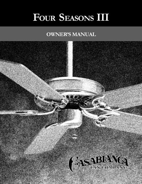
OUR SEASONS IIIOWNER’S MANUAL
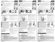
• The blades in each pack are matched for equalweight to assure smooth fan operation. Ifmore than one fan is being installed, becareful not to mix blades from differentcartons.• Inspect the contents of your carton forpossible shipping or handling damage andreport any such damage directly to yourauthorized <strong>Casablanca</strong> dealer.• It is always a good idea to have an assistantto help with the installation.• When cleaning, painting, or working nearyour fan, be very careful of the fan and blades.Always turn the power OFF to the ceiling fanbefore servicing it, working on it, or replacinglight bulbs.• Never insert anything into the path of thefan blades while the fan is in operation.• Never install a fan over a pool or spa.• Never operate a fan that has been damagedin any way. Contact <strong>Casablanca</strong> <strong>Fan</strong> Companyby calling toll free 1-888-227-2178, orcontact your local authorized <strong>Casablanca</strong>dealer for assistance in obtaining service.CONTENTSINTRODUCTION . . . . . . . . . . . . . . . . . . . . . . . . . . . . . . . . . . . . . . . . . . . . . . . . . . . . . . . . . . . . . . . . . . . . . . 1MOUNTING RECOMMENDATIONS . . . . . . . . . . . . . . . . . . . . . . . . . . . . . . . . . . . . . . . . . . . . . . . . . . . . . . . . . . 2PREPARATION INSTRUCTIONS . . . . . . . . . . . . . . . . . . . . . . . . . . . . . . . . . . . . . . . . . . . . . . . . . . . . . . . . . . . 3FAN INSTALLATION (USA) . . . . . . . . . . . . . . . . . . . . . . . . . . . . . . . . . . . . . . . . . . . . . . . . . . . . . . . . . . . . . . . 4FAN INSTALLATION (OUTSIDE USA) . . . . . . . . . . . . . . . . . . . . . . . . . . . . . . . . . . . . . . . . . . . . . . . . . . . . . . . . 8CONTROL FEATURES:3-SPEED CONTROL WIRING . . . . . . . . . . . . . . . . . . . . . . . . . . . . . . . . . . . . . . . . . . . . . . . . . . . . . . . . . . . 123-SPEED OPERATIONS . . . . . . . . . . . . . . . . . . . . . . . . . . . . . . . . . . . . . . . . . . . . . . . . . . . . . . . . . . . . . . . 13TROUBLESHOOTING . . . . . . . . . . . . . . . . . . . . . . . . . . . . . . . . . . . . . . . . . . . . . . . . . . . . . . . . . . . . . . . . . . . 14READ AND SAVE THESE INSTRUCTIONSSAFETY FIRSTSafety and the proper operation of your <strong>Casablanca</strong> fan both require a thorough knowledge of the productand proper installation; therefore, before attempting to install and operate your <strong>Casablanca</strong> fan, read thisowner’s manual completely and carefully. Retain this manual for future reference.CAUTION: To avoid possible electrical shock, make certain that electricity is turned off atthe circuit breaker or fuse box before attempting any installation procedure.BEFORE YOU START• All wiring must be in accordance with the National Electric Code ANSI/NFPA 70-1993 and the appropriate local electricalcodes. The National Electric Code requires proper grounding as a precaution against electrical shock. A qualified electricianshould be consulted if you are unsure.• This fan is designed to be installed on an existing electrical outlet box. The outlet box must be UL Listed for ceiling faninstallations, if it is not, a new box must be installed. <strong>Casablanca</strong> extension poles are available for sloped or high ceilinginstallations.• This ceiling fan requires a grounded electrical supply of 120 VAC, 60 Hz and a minimum 15 amp circuit. The maximumcurrent requirement for the fan with light fixture is 3.8 amps. The fan uses about 1 amp or 100 watts. Maximum lightcurrent is 2.8 amps or 340 watts of lighting.• Where wire nuts are employed, be sure all bare wires are within the connectors. When installing the canopy hatch, makesure all wires are within the canopy and that no wires are being pinched.For best performance and for your warranty to be valid,use only genuine <strong>Casablanca</strong> blades, light fixtures, and accessories.SAFE USEP/N 8943150 REV.BFUSE BOX(REMOVE FUSE FOR THECIRCUIT YOU WILL BEWORKING ON)CIRCUIT BREAKER(TRIP BREAKER FOR THECIRCUIT YOU WILL BEWORKING ON)P/D MAR00PDG18"70"84"1
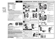
MOUNTING RECOMMENDATIONSBefore mounting your <strong>Casablanca</strong> fan, read the following helpful recommendations. The location of the fan, air circulation,and fan size are all important factors to consider before installation.LocationCeiling fans have practical uses in almost every room in your home. We suggest you follow these mountingrecommendations as you decide where to install your <strong>Casablanca</strong> fan.• For safety reasons, the fan blades must be a minimum of 7' above the floor.• Do not locate the fan in a doorway or above a swinging door.• In any installation, the tips of the blades must be at least 18" from the wall in order toprovide sufficient clearance for the blades.• In bedrooms, fans work best when mounted above the foot of the bed.• Over pool tables, be sure to provide plenty of clearance to avoid damage frompool cues.• In low ceiling locations, our optional Low Ceiling Adaptor (LCA)—available atextra cost—can be used to gain 3 1 ⁄ 2".• In kitchens be sure to allow for open cupboard doors to clear the fan blades.• Do not install a fan close to, or over, a pool or spa. High humidity combined<strong>Fan</strong> with Size corrosive gases will destroy the finish and warp the blades.Variable fan speed capability permits the use of a full-size 52" fan even insmaller rooms. For very large rooms, two fans may be needed.Suggested Extension Pole LengthsCeiling Height Pole Length8'Standard8' 6" Standard9'6"9' 6"12"10'12"11'18"12'24"13'36"14'48"SLOPED CEILING INSTALLATIONSEXTENSIONPOLEMAXIMUMHANG-TRU®ANGLE 32º32°BLADES MUST BE AMINIMUM OF 7′ABOVE THE FLOORWhen to Use Extension PolesFor best performance and best appearance,an extension pole should be used withyour <strong>Casablanca</strong> fan when installing onhigh (cathedral) ceilings or slopedceilings. <strong>Casablanca</strong> offers standard polesin increments of 6" up to 5'. Custom polesare available in lengths up to 10'. See yourAuthorized <strong>Casablanca</strong> Dealer for details.7′ MINIMUMNote: <strong>Fan</strong> may wobble or vibrate ifpole length is not long enough andinside blade is too close to downslopeor side wall. Extending pole lengthwill usually solve problem.Calculation of 32°Use the tear-off Ceiling Angle Template card inserted in theback of this manual, it provides you with a simple ‘go’ or‘no-go’ for installing your fan on a sloped ceiling.2EXAMPLE 1This slope is less than 32˚.It is OK to install your fan.EXAMPLE 2This slope is 32˚. This is the maximumslope that will allow the fan to hangstraight down. It is OK to install yourfan.EXAMPLE 3This slope is more than 32˚.Your fan will not hang straight down, anadaptor is necessary. Contact your localAuthorized <strong>Casablanca</strong> Dealer in regardsto purchasing a “Slope Ceiling Adaptor.”
FOUR SEASONS IIIPREPARATION INSTRUCTIONSUnpacking: Before assembling and installing your ceiling fan, remove all parts from the shipping cartons and check themagainst the parts listed here. Before discarding packaging material, be certain that all parts have been removed.Carton ContentsThe fan carton contains the fan body, warranty card, owner'smanual, and all the parts necessary to assemble and installyour <strong>Casablanca</strong> ceiling fan. These parts are shown at thestart of each installation section. Before you start, go throughthis Owner’s <strong>Manual</strong> and confirm that you have all the partsshown in each section.GETTING STARTEDPERMA•LOCK HARDWAREBe sure to use only genuine <strong>Casablanca</strong> blades. The bladeshrink wrap holds 5 blades of matched weight. If more thanone fan is being installed, be sure not to mix blade sets.CAUTION: When removing the shrink wrap,be careful not to scratch the blades.ALLEN SET SCREW1⁄4-20 x 1 ⁄4"(PRE-INSTALLED)3mmALLEN WRENCHFAN PREPARATIONDOWNROD & BALLASSEMBLYIMPORTANT SAFETY INFORMATION!BEFORE STARTING THE INSTALLATION OF YOUR CEILING FAN, INSTALL THETHREADED DOWNROD INTO THE MOTOR COUPLING AND LOCK THE ASSEMBLYPrepare for fan installation as follows:Step A. Route the wires from the motor through thePerma•Lock downrod and ball assembly.MOTORWIRESGROUNDWIRETip: The downrod has a tapered threadthat is designed to lock completely whencorrectly installed.Step B. Using the provided allen wrench, loosen the set screwseveral turns to allow installation of the downrod. Threadthe downrod into the motor coupling until it stops turning,this will take at least four and a half full turns.TAPEREDTHREADDOWNROD& BALLASSEMBLYStep C. Securely tighten the set screw with the provided allenwrench to ensure safe operation of your fan.CAUTION: Failure to fully lock in the downrodbefore securely tightening the allen setscrew may cause the fan to separate fromthe downrod during normal operation!ALLENSET SCREWMOTORCOUPLINGInstalling a New Ceiling Fixture Outlet BoxIf you do not have an existing fixture located where you wishto place your <strong>Casablanca</strong> fan, an approved ceiling fixtureoutlet box must be installed and wired.WARNING: To reduce the risk of fire, electrical shock,or personal injury, mount to outlet box markedacceptable for ceiling fan support using themounting hardware provided with the outlet box.GETTING STARTEDUsing Existing Ceiling Fixture Outlet BoxAfter turning the power OFF at its source (either circuit breakeror fuse box), lower the old fixture and disconnect the wiring.Check the ceiling fixture outlet box to be sure that it ismarked ‘Approved for ceiling fan mounting’. If it is not, a newbox must be installed.NOTE: The fan weight is 17 pounds.3
FOUR SEASONS IIICROSSBAR MOUNTING BRACKET INSTALLATIONFOR FAN INSTALLATION OUTSIDE THEUSA GO TO PAGE 8EXCLUDING MODELS ENDING IN ‘E’CEILING FANAPPROVEDWIRING BOXProceed with installation as follows:Step 1. Route the wires from the ceiling outlet box throughthe crossbar mounting bracket center hole. Attach the bracket,with ground wire and ridges down, to the ceiling fixture outletbox with the mounting hardware included with the outletbox.Tighten the screws firmly by hand only, being careful not tobend the bracket by over tightening.CROSSBARMOUNTINGBRACKETCEILINGWIRINGRIDGESIDEDOWNCAUTION: To reduce the risk ofpersonal injury, use only themounting hardware provided withthe approved outlet box to installthe crossbar mounting bracket.FLATWASHERCANOPY HARDWAREAPPROVEDOUTLETBOXHARDWAREGREENGROUNDWIRECANOPY SCREW (4)CANOPYHATCHStep 2. Attach the canopy to the crossbarmounting bracket with three of the 8-32 x 2 1 / 4"long canopy screws and canopy lock washers.Tighten the screw firmly by hand only.CANOPYCANOPY INSTALLATIONCANOPY LOCK WASHER (4)CROSSBARMOUNTINGBRACKETNOTE: On sloped ceilings, align thecanopy opening towards the top orroom peak.CANOPYCANOPY LOCKWASHERCANOPYSCREW4
FOUR SEASONS IIISWITCH HOUSING INSTALLATIONSWITCHHOUSINGTIP: The packing styrofoam makes a handy work bench.Remove the bottom foam from the box.Step 3. Outside USA—Excluding Models Ending in ‘E’Note: If you have a fan with a secondary support steelcable running through your fan motor, go to Page 8.MOTORCONNECTOR(PLUG)STEEL CABLE(OUTSIDE USAINSTALLATION)Step 4. Hold the switch housing close to the fan andconnect the motor plug to the switch housing socket.The connectors are keyed to ensure correct alignmentduring installation - Do not force!Step 5. Remove the three mounting screws from theswitch housing plate ready for the next step.MOUNTINGSCREW(3)SWITCHHOUSINGCONNECTOR(SOCKET)SWITCHHOUSINGPLATEStep 6. Position the switch housing assembly on theswitch housing plate and align the holes in the switchhousing with the holes in the plate. Secure the switchhousing assembly by reinstalling the three screwsremoved in the previous step.SWITCH HOUSING INSTALLATIONCAUTION! Do not pinch wires between the switchhousing assembly and the plate.MOUNTINGSCREW(3)5
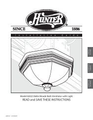
CROSSBAR MOUNTING HANGING BRACKET THE FANINSTALLATIONStep 7. To hang the fan body in the canopy,hold the fan body firmly and insert the ballinto the canopy opening. Check that no wireswere pinched. Rotate the fan body until theslot in the nylon ball fits into the pin oppositethe canopy opening.Step 8a. Attach the fan wires to the ceiling fixture outletbox wiring by twisting the bare ends of the wires togetherand then securing with a wire nut. Test that the connectionis secure by pulling on the wire nut. Connect in this order:Step 8c. W-8 Wiring Connections• GREEN leads from mounting plate and fan to GROUNDconductor of power source. Secure with wire nut.• WHITE wire from fan to white NEUTRAL wire in ceilingfixture outlet box. Secure with wire nut.• BLACK power wire from fan to RED wire from W-8 in ceilingoutlet box. Secure with wire nut.• BLUE wire from fan to YELLOW wire from W-8 in ceilingoutlet box. Secure with wire nut.NOTE: SEE PAGE 12 FOR ADDITIONAL WIRING INFORMATION.Step 9. Tuck the wires into the canopywith the wire nuts pointed upwards, sothat the WHITE and BLACK wires are onopposite sides of the canopy and all wiresare clear of the canopy opening.Step 10. Install canopy hatch with thelast canopy screw and lock washer. To dothis, tilt the fan body away from the hatchopening.Tighten the screws firmly by hand only.Step 11. Straighten the fan, then checkto ensure that there is no movementbetween the canopy and ceiling or Hang-Tru ball and top support shaft.FOUR SEASONS IIINOTE: The fan weight is 17 pounds.NOTE: Independent control of thelight fixture using a W-8 requires anadditional power wire run from thewall switch to the fan. See Page 12for wiring.D1OPTIONWIREBALLSLOTCANOPY ELECTRICAL CONNECTIONSStep 8b. Pull Chain or W-4 Wiring Connections• GREEN leads from mounting plate and fan to GROUNDconductor of power source. Secure with wire nut.• WHITE wire from fan to white NEUTRAL wire in ceiling fixtureoutlet box. Secure with wire nut.• BLUE wire and BLACK power wire from fan to BLACK powerwire in ceiling outlet box. Secure with wire nut.PINCAPPED BLUE D1-OPTION WIRE ON 3-SPEED ONLYFOR INDEPENDENT W-8 LIGHT CONTROLWIRE NUT2 BLACK & BLUED1-OPTION WIRES(WITHOUT W-8)2 WHITE WIRESBLUE & YELLOWWIRESBLACK & REDWIRES2 WHITE WIRESCANOPY HATCH INSTALLATIONLOCKWASHERCANOPYHATCHCANOPYSCREW3 GREEN WIRES3 GREEN WIRESPULL CHAIN ORW-4 CONNECTIONSW-8 CONNECTIONSTILT THEFAN TOINSTALLLASTCANOPYSCREW6
FOUR SEASONS IIIBLADE & BLADE HOLDER HARDWAREBLADEHOLDERBLADE SCREW(3 PER BLADE)FLAT WASHER(3 PER BLADE)BLADE HOLDER SCREW(2 PER BLADE)BLADE & BLADE HOLDER INSTALLATIONBLADE SCREW(3 PER BLADE)FLAT WASHER(3 PER BLADE)Step 12. Attach the blades to theblade holders with the three bladescrews and flat washers providedfor each blade.Hand tighten securely.Install the assembled blade andblade holder to the fan motor.Hand tighten securely.Repete for each assembly.Step 13. Attach the pull chain fob.BLADE HOLDERSCREW(2 PER BLADEHOLDER)PROCEED TO YOUR FAN’SCONTROL FEATURE SECTION ONTHE PAGE 13.FOB7
FAN INSTALLATION OUTSIDE THE USA - EXCLUDING MODELS ENDING IN ‘E’If you do not have an existing fixture located where you wish to place your <strong>Casablanca</strong> fan, a new ceiling fixture outlet boxmust be installed (use an outlet box marked acceptable for fan support) and an electrical cable to run it. This box must besecured to the ceiling according to the outlet box manufacturer’s instructions. It is recommended that this be done bya qualified electrician.Vaulted or Cathedral Ceiling InstallationsYour <strong>Casablanca</strong> fan may be installed on a vaulted or cathedral ceiling in the same manner as described for a flat ceiling. TheHang-Tru ® mounting system makes it possible to hang your fan on sloped ceilings up to a 32° angle.Using Existing Ceiling Fixture Outlet BoxAfter turning electrical power off, lower the old fixture to expose the wiring and the ceiling fixture outlet box. Cut thefixture wires or if wire nuts have been used, unscrew them and disconnect the wires. The fixture can then be removed.After removing the old fixture, check the outlet box to sure that it is supported by a joist or beam across its upper surface.If not, a 2" x 4" stud must be installed.OUTLETADAPTORPLATEFOUR SEASONS III (OUTSIDE USA INSTALLATION)OUTSIDE USA - SECONDARY SUPPORT INSTALLATION PARTS6" OUTLET BOXCABLE3⁄ 8 "- 7 LAG SCREW (5") FENDERWASHERSPRING LOCKHOOKOUTSIDE USA - MOUNTING SECONDARY SUPPORT PARTS TO OUTLET BOXWARNING: MOUNT ONLY TO AN OUTLET BOXMARKED ACCEPTABLE FOR FAN SUPPORT••••ADVERTISSEMENT: ASSEMBLER UNIQUEMENT ÀUNE BÔITE DE SORTIE JUGÉE ACCEPTABLE POURRETENIR UN VENTILATEUR.JOISTORBEAMBefore beginning Step 1, follow Steps A-C on Page 3.Step 1. Remove the knockout plug in the center of the outletbox or drill a 1 ⁄ 2 " hole for the lag screw to pass through. Thendrill a 1 ⁄ 4 " guide hole into the joist or beam to a depth of3inches.Step 2. Route the outlet box wires through the 1 ⁄ 2 " diameterouter hole of the outlet adaptor plate.Step 3. Line up the slotted holes and four canopy screwholes in the crossbar mounting bracket and outlet adaptorplate with the 8-32 mounting holes in the outlet box. Installthe two 8-32 X 2 1 ⁄ 4 " (1") screws and flat washers in fanhardware kit and tighten securely by hand only!Step 4. With fender washer and outlet box cable attached asshown, pass lag screw through center hole of outlet adaptorplate and screw into pre drilled 1 ⁄ 4 " guide hole of joist. Tightenuntil outlet box is firmly mounted.TIP: Threading two of the canopy screws into thecrossbar mounting bracket will help everything stayaligned as you tighten the lag screw. Remove thembefore starting Step 12.81⁄ 4 " GUIDEHOLECROSSBARMOUNTINGBRACKETOUTLETADAPTORPLATE8-32 X 2 1 ⁄ 4 "(1") SCREW6" OUTLET BOXCABLEFENDERWASHEROUTLETBOX1⁄ 2 "HOLELAGSCREW
OUTSIDE USA - SECONDARY SUPPORT ♦ PREPARING THE SWITCH HOUSINGStep 5. Hold the switch housing close to the fanand connect the motor plug to the switch housingsocket. The connectors are keyed to ensure correctalignment during installation - Do not force!Step 6. Locate the blue and white LIGHT wires inthe switch housing. Make sure they are NOTconnected.Step 7. Check the tightness of the Cable Clamp &Screw. (The clamp should not slip along the cable.)FOUR SEASONS III (OUTSIDE USA INSTALLATION)SWITCHHOUSINGStep 8. Tape completely over the end of the CableClamp and the end of the Secondary Support Cablewith electrical tape.TAPED OVERCABLE CLAMP& SCREWCABLECLAMP& SCREWSECONDARYSUPPORTCABLESWITCHHOUSINGCONNECTOR(SOCKET)MOTORCONNECTOR(PLUG)Step 9. Pull the cable through the other side ofthe fan to snug the cable clamp. This makes iteasier to install the switch housing.Step 10. Remove the three mounting screws fromthe switch housing plate. (Keep them for the nextstep).NYLONSTOPSWITCHHOUSINGPLATEMOUNTINGSCREW(3)OUTSIDE USA - SECONDARY SUPPORT ♦ SWITCH HOUSING INSTALLATIONStep 11. Position the switch housing assembly onthe switch housing plate and align the holes inthe switch housing with the holes in the plate.Secure the switch housing assembly by reinstallingthe three screws removed in the previous step.CAUTION! Do not pinch wiresbetween the switch housingassembly and the plate.MOUNTINGSCREW(3)9
FOUR SEASONS III (OUTSIDE USA INSTALLATION)OUTSIDE USA - SECONDARY SUPPORT ♦ CANOPY INSTALLATIONStep 12. Attach the canopy to the crossbar mounting bracket behindthe installed outlet adaptor plate with three of the 8-32 x 2 1 ⁄2" longcanopy screws and lock washers provided with your <strong>Casablanca</strong> fan.Hand tighten until snug against the ceiling.NOTE: On sloped ceilings, align the canopy openingtoward the top or peak of the room.Step 13. Attach the spring lock hook to the fan cable by depressingthe spring lock and clipping onto the loop at the end.FANCABLESPRINGLOCKSPRINGLOCK HOOKFEED OUTLET BOXCABLE AND OUTLETBOX WIRESTHROUGH CANOPYOPENINGCANOPYLOCKWASHERCANOPYSCREWOUTSIDE USA - SECONDARY SUPPORT ♦ HANGING THE FANStep 14. To hang the fan body in the canopy, holdthe fan body firmly and insert the nylon ball into thecanopy opening. Rotate fan body until slot on nylonball fits into pin opposite canopy opening.Step 15. Attach the fan wires to the ceiling outletbox wiring by twisting the bare ends of the wiringtogether:• White wire from fan to white NEUTRAL wire in ceilingoutlet box.• Black wire and blue wire from fan to black (or red)POWER wire in ceiling outlet box.• Green leads from crossbar mounting bracket andfan to grounding conductor of power source.Secure by threading on the wire nuts provided withthe fan.FANCABLEBALLOUTLETBOXCABLESLOTCANOPYPINNOTE: SEE PAGE 12 FOR ADDITIONAL WIRINGINSTRUCTIONS.10
FOUR SEASONS III (OUTSIDE USA INSTALLATION)OUTSIDE USA - SECONDARY SUPPORT ♦ COMPLETING INSTALLATIONStep 16. Attach the fan cable to outlet box cable with thespring lock hook. Make sure the spring lock is tightly closed.Step 17. Tuck the wires into the canopy with the wire nutspointed upward, so that the white and black wires are onopposite sides of the canopy and all wires are clear of thecanopy opening. Tuck the extra cable and screw lock hookinto the canopy.WIRE NUTSINSTALLEDNOTE: International fans and light fixtures are suppliedwith plug and socket connectors. Substitute these connectorsfor the wire nuts shown throughout this manual.FAN AND OUTLETCABLES SECURED BYSPRING LOCK HOOKOUTSIDE USA - BLADE & BLADE HOLDER HARDWAREBLADEHOLDERBLADE SCREW(3 PER BLADE)FLAT WASHER(3 PER BLADE)BLADE HOLDER SCREW(2 PER BLADE)OUTSIDE USA - BLADE & BLADE HOLDER INSTALLATIONStep 18. Attach the blades to theblade holders with the three bladescrews and flat washers providedfor each blade. Hand tightensecurely.Step 19. Install the assembledblade and blade holder to the fanmotor. Hand tighten securely.Repete for each assembly.Step 20. Attach the pull chain fob.PROCEED TO PAGE 13.BLADE SCREW(3 PER BLADE)FLAT WASHER(3 PER BLADE)FOBBLADE HOLDERSCREW(2 PER BLADEHOLDER)11
R3-SPEED• The W-4 allows the choice of four (4)different speed settings.• No light fixture is used.• Set the FAN pull chain switch to theHIGH speed setting.• No changes in household or fan wiringare required.• The fan may be turned ON and OFF bythe W-4 wall control.3-SPEED ♦ W-4 WALL CONTROL OF THE FANCAUTION! Failure to set the pull-chainspeed to HIGH can result in faultyoperation of the fan and damage tothe W-4 wall control. To confirm fanis set to HIGH: Turn W-4 fan speedswitch to 'HI' - set fastest fan speedwith pull chain.3-SPEED ♦ W-8 WALL CONTROL OF THE FAN & LIGHT(S)• The fan may be turned ON and OFFby the W-8 wall control.• The lights may be turned ON andOFF by the W-8 and the intensityadjusted from low to high.• The fan must be supplied with twoindependent 120V AC supplywires.• Set the FAN pull chain switch tothe HIGH speed setting.• Turn the lights ON at the fan.• The W-8 allows the choice of four(4) different speed settings.CAUTION! Failure to set the pullchainspeed to HIGH can result infaulty operation of the fan anddamage to the W-8 wall control.To confirm fan is set to HIGH: TurnW-8 fan speed switch to 'HI' - setfastest fan speed with pull chain.12
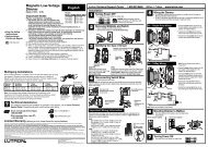
RPull-chain switches on the fan control the fan and lights.Using the fan control pull-chain switch: <strong>Fan</strong> off at start.• First pull: fan ON, low speed• Second pull: medium speed• Third pull: high speed• Fourth pull: fan OFFUsing the optional light pull-chain switch: Light off at start.• First pull: light ON• Second pull: light OFFDirection of blade rotation is controlled by the reverse slideswitch on the side of the switch housing.No changes in household wiring are required.3-SPEED ♦ OPERATIONOPTIONAL LIGHTPULL CHAINSWITCHREVERSESWITCH3-SPEED ♦ OPTIONAL WALL CONTROL ♦ W-4The W-4 wall control provides four-speed control of fan from a convenient wall location. TheW-4 is designed to replace a standard wall switch and will fit wall boxes with a depth of 2"or greater. Not for use with single pull-chain fan/light option wiring.To install a W-4 wall control in place of an existing wall switch, follow the instructions onthe W-4 package.Note: No rewiring is required if the fan is replacing an existing light fixture.Operation of the fan from the wall switch is simple:1. Turn knob to obtain desired speed setting.CAUTION! Failure to set the pull-chain speed to HIGH can result in faulty operation ofthe fan and damage to the W-4 wall control. To confirm fan is set to HIGH: Turn W-4 fanspeed switch to 'HI' - set fastest fan speed with pull chain.3-SPEED ♦ OPTIONAL WALL CONTROL ♦ W-8The W-8 wall control provides separate control of fan and light with two separate knobs froma convenient wall location. The W-8 is designed to replace a standard wall switch and wallboxes with a depth of 2" or greater. Requires two hot leads from wall box to ceiling wiringbox.To install a W-8 wall control in place of an existing wall switch, follow the instructions onthe W-8 package.Operation of the fan from the wall switch is simple:1. Turn the upper knob to the desired fan speed.2. Turn the lower knob to the desired light setting.CAUTION! Failure to set the pull-chain speed to HIGH can result in faulty operation ofthe fan and damage to the W-8 wall control. To confirm fan is set to HIGH: Turn W-8 fanspeed switch to 'HI' - set fastest fan speed with pull chain.SAVING MONEY WITH YOUR CEILING FAN3-SPEEDFAN & SPEEDCONTROLPULL CHAIN SWITCHLOIN SUMMER, the movement ofair creates a cooling “wind chill”effect. A room can actually feelseveral degrees cooler, without settingthe thermostat lower.IN WINTER, hot air rises to theceiling while cool air settles to thefloor. Trapped against the ceiling,the warm air is wasted. If you turnup the thermostat, energy costswill rise.RUNNING IN REVERSE, your<strong>Casablanca</strong> fan can recirculatewarm air near the ceiling downinto the living area, providing evenheating and comfort (with a pleasanteffect on heating bills).13
3-SPEEDTROUBLESHOOTINGBEFORE REQUESTING SERVICE:Please follow this troubleshooting guide before contacting your dealer for assistance.Caring for Finishes: For cleaning, a soft brush or lint-free clothshould be used to prevent scratching the finish. A vacuum cleanerbrush nozzle can remove heavier dust. Surface smudges or an accumulationof dirt and dust can easily be removed by using a milddetergent and slightly dampened soft cloth. An antistatic agentmay be used, but never use abrasive cleaning agents. These willdamage the finish. Painted and high-gloss blades may be cleanedin the same manner.Blades: Wood finish blades should be cleaned with a furniture polishingcloth. Occasionally, a light coat of furniture polish may beapplied for added protection and beauty.Never Lubricate this <strong>Fan</strong>!The precision motor at the heart of your <strong>Casablanca</strong> fan featuressealed bearings that are lubricated for life. Do not attempt to oilthe motor.Changing Light BulbsBe sure to turn power to the fan OFF at the wall switch or circuitbreaker before changing light bulbs. Replace bulbs with same typeas removed from the fixture. Each fan is rated for a maximum TOTALwattage of lighting.Exceeding the rated maximum allowable wattage for the fan willburn out the fan electronics module and void the warranty.PROBLEMFAN WILL NOT STARTFAN WOBBLES OR SHAKESEXCESSIVELYFAN NOISY DURINGOPERATIONBREAK-IN PERIODDOES NOT RUN ONLOW SPEED3-SPEEDCheck main circuit fuses, circuit breakers, or wall switch position.Check all wire connections, making sure the power is turned off during this inspection.Check that reverse switch is not set in center of throw.Be sure canopy pin is properly set into the slot on the ball.Check the screws holding the blade holders to the flywheel (or direct drive motor). Tighten as necessary.Check that bladeholders have not been bent during installation.Check and tighten light fixture retaining screws, glass shade screws and/or the light bulb(s) as neccessary.Tighten the blade to bladeholder screws.Tighten canopy screws and mounting plate assembly.Check and tighten blade holders to flywheel (or direct drive motor).Make sure all screws in the motor housing are snug, but not overly tight.Check that the wire nuts inside the canopy and switch housing are not touching the metal parts or havefallen off the wire splices. Tighten or adjust as necessary.Let fan run at high speed for two (2) hoursIf new, “break-in” may be required - run at higher speed for several daysPOSSIBLE REMEDIES..FAN RUNS SLOWLY IN EITHER DIRECTION IF ROTATION IS STARTED BY HAND; WILL NOT REVERSE: Defective reverse switch; defectivecapacitor; or open motor winding: Replace reverse switch assembly; replace PCB assembly; or replace motor unit.FAN WILL NOT OPERATE AT PROPER SPEEDS OR WILL NOT OPERATE AT ANY SPEED: Defective three-speed pull-chain switch assembly; ordefective capacitor: Replace three-speed pull-chain switch assembly; or replace PCB assembly.For questions or to locate the nearest<strong>Casablanca</strong> Authorized Service Centercall toll free:1-888-227-2178or visit us on the web at:www.<strong>Casablanca</strong><strong>Fan</strong>Co.com14
761 CORPORATE CENTER DRIVE • POMONA, CA 91768TOLL FREE: 888-CASA-1ST (227-2178)www.<strong>Casablanca</strong><strong>Fan</strong>Co.com©COPYRIGHT 1999 CASABLANCA FAN COMPANY • U.S. PATENT PENDINGPRINTED IN ROC