LM Guide THK - Industrial Technologies
LM Guide THK - Industrial Technologies
LM Guide THK - Industrial Technologies

You also want an ePaper? Increase the reach of your titles
YUMPU automatically turns print PDFs into web optimized ePapers that Google loves.
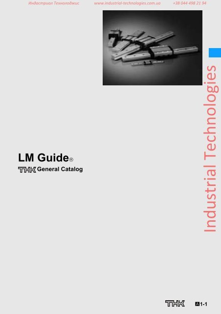
Индастриал Технолоджис www.industrial‐technologies.com.ua +38 044 498 21 94<strong>LM</strong> <strong>Guide</strong>General Catalog<strong>Industrial</strong> <strong>Technologies</strong>A1-1
Индастриал Технолоджис www.industrial‐technologies.com.ua +38 044 498 21 94<strong>LM</strong> <strong>Guide</strong>General CatalogA Technical Descriptions of the ProductsFeatures and Types................................ A1-4Features of the <strong>LM</strong> <strong>Guide</strong> ...................... A1-4• Large Permissible Load and High Rigidity ... A1-5• High Precision of Motion........................... A1-7• Accuracy Averaging Effect by Absorbing Mounting Surface Error .. A1-10• Easy Maintenance ................................... A1-12• Improved Productivity of the Machine ......... A1-12• Substantial Energy Savings....................... A1-13• Low Total Cost ........................................ A1-14• Ideal Four Raceway, Circular-Arc Groove,Two-Point Contact Structure..................... A1-15• Superb Error-Absorbing Capability with the DF Design.. A1-19Classification Table of the <strong>LM</strong> <strong>Guide</strong>s.. A1-20Point of Selection ................................... A1-22Flowchart for Selecting an <strong>LM</strong> <strong>Guide</strong> ... A1-22Selecting a Type ..................................... A1-24• Types of <strong>LM</strong> <strong>Guide</strong>s................................. A1-24Setting Conditions ................................. A1-34• Conditions of the <strong>LM</strong> <strong>Guide</strong>....................... A1-34Calculating the Applied Load................ A1-50• Rated Load of an <strong>LM</strong> <strong>Guide</strong> in Each Direction.. A1-50• Calculating an Applied Load...................... A1-51Calculating the Equivalent Load........... A1-70Calculating the Static Safety Factor ..... A1-71Calculating the Average Load............... A1-72• Example of Calculating the Average Load (1)- with Horizontal Mount and Acceleration/Deceleration Considered .. A1-74• Example of Calculating the Average Load (2)- When the Rails are Movable................... A1-75Calculating the Nominal Life ................. A1-76• Nominal Life Equation for an <strong>LM</strong> <strong>Guide</strong> Using Balls. A1-76• Rated Life Equation for an <strong>LM</strong> <strong>Guide</strong> Using Rollers . A1-76• Example of Calculating the Nominal Life (1)- with Horizontal Mount and High-speed Acceleration..• Example of Calculating the Nominal Life (2)- with Vertical Mount................................A1-79A1-84Predicting the Rigidity ........................... A1-87• Selecting a Radial Clearance (Preload)....... A1-87• Service Life with a Preload Considered....... A1-88• Rigidity................................................... A1-88• Radial Clearance Standard for Each Model . A1-89Determining the Accuracy..................... A1-92• Accuracy Standards................................. A1-92• <strong>Guide</strong>lines for Accuracy Grades by Machine Type. A1-93• Accuracy Standard for Each Model ............ A1-94Feature of Each Model ........................... A1-105Structure and Features of the Caged Ball <strong>LM</strong> <strong>Guide</strong>... A1-106• Advantages of the Ball Cage Technology.... A1-107Caged Ball <strong>LM</strong> <strong>Guide</strong> ............................. A1-112• Model SHS ............................................. A1-112• Model SSR ............................................. A1-118• Model SNR/SNS...................................... A1-124• Model SHW ............................................ A1-132• Model SRS ............................................. A1-136• Model SCR ............................................. A1-142• Model EPF.............................................. A1-146<strong>LM</strong> <strong>Guide</strong> ................................................. A1-152• Model HSR ............................................. A1-152• Model SR ............................................... A1-160• Model NR/NRS........................................ A1-168• Model HRW ............................................ A1-176• Model RSR ............................................. A1-182• Model RSR-Z .......................................... A1-190• Model RSH ............................................. A1-196• Model RSH-Z .......................................... A1-200• Model HR ............................................... A1-206• Model GSR............................................. A1-212• Model GSR-R ......................................... A1-218• Model CSR ............................................. A1-226• Model MX............................................... A1-230• Model JR................................................ A1-234• Model HCR............................................. A1-240• Model HMG ............................................ A1-244• Model NSR-TBC...................................... A1-250• Model HSR-M1........................................ A1-254• Model SR-M1.......................................... A1-262• Model RSR-M1........................................ A1-268• Model HSR-M2........................................ A1-274Structure and Features of the Caged Roller <strong>LM</strong> <strong>Guide</strong> ... A1-278• Advantages of the Caged Roller Technology . A1-279Caged Roller <strong>LM</strong> <strong>Guide</strong> .......................... A1-282• Model SRG............................................. A1-282• Model SRN ............................................. A1-288• Model SRW ............................................ A1-294Point of Design ....................................... A1-300Designing the <strong>Guide</strong> System................. A1-300• Examples of Arrangements of the <strong>Guide</strong> System. A1-300• Method for Securing an <strong>LM</strong> <strong>Guide</strong> to Meet the Conditions.. A1-304Designing a Mounting Surface.............. A1-306• Designing a Mounting Surface................... A1-306• Shoulder Height of the Mounting Base and the Corner Radius . A1-308• Permissible Error of the Mounting Surface... A1-315• Marking on the Master <strong>LM</strong> <strong>Guide</strong> and Combined Use.. A1-320Mounting Procedure and Maintenance.... A1-322Mounting the <strong>LM</strong> <strong>Guide</strong>.......................... A1-322• Mounting Procedure................................. A1-322• Methods for Measuring Accuracy after Installation A1-332• Recommended Tightening Torque for <strong>LM</strong> Rails . A1-332<strong>Industrial</strong> <strong>Technologies</strong>A1-2
Индастриал Технолоджис www.industrial‐technologies.com.ua +38 044 498 21 94B Product Specifications (Separate)Options.................................................... A1-333Contamination Protection ..................... A1-334• Seal and Metal Scraper............................ A1-334• Laminated Contact Scraper LaCS.............. A1-335• Light-Resistance Contact Seal LiCS........... A1-337• Dedicated bellows ................................... A1-338• Dedicated <strong>LM</strong> Cover ................................ A1-338• Cap C.................................................... A1-339• Cap GC ................................................. A1-340• Plate Cover SV -- Steel Tape SP ................. A1-342Lubrication.............................................. A1-345• QZ Lubricator ......................................... A1-345• Lubrication Adapter ................................. A1-348• Removing/mounting Jig............................ A1-349• End Piece EP ......................................... A1-350List of Parts Symbols ............................ A1-352Table of Supported Options by Models... A1-354Dimensions of Each Model with an Option Attached• Seal resistance value............................... A1-356• Resistance of LaCS................................. A1-359• Maximum Seal Resistance of LiCS ............ A1-360• Greasing Hole......................................... A1-361Model No. ................................................ A1-366• Model Number Coding ............................. A1-366• Notes on Ordering ................................... A1-368Precautions on Use................................ A1-370Precautions on Using the <strong>LM</strong> <strong>Guide</strong> .... A1-370Precautions on Using Options for the <strong>LM</strong> <strong>Guide</strong> .. A1-371• QZ Lubricator for the <strong>LM</strong> <strong>Guide</strong> ................. A1-371• Laminated Contact Scraper LaCS, Side Scraper for <strong>LM</strong> <strong>Guide</strong>s A1-371• Light Contact Seal LiCS for <strong>LM</strong> <strong>Guide</strong>s ...... A1-371• Cap GC ................................................. A1-372Dimensional Drawing, Dimensional TableCaged Ball <strong>LM</strong> <strong>Guide</strong>• Model SHS.............................................B1-5• Model SSR............................................. B1-15• Model SNR/SNS ..................................... B1-25• Model SHW ............................................ B1-43• Model SRS............................................. B1-49• Model SCR............................................. B1-57• Model EPF ............................................. B1-63<strong>LM</strong> <strong>Guide</strong>• Model HSR............................................. B1-67• Model SR ............................................... B1-91• Model NR/NRS ....................................... B1-99• Model HRW............................................ B1-113• Model RSR............................................. B1-119• Model RSR-Z.......................................... B1-129• Model RSH............................................. B1-135• Model RSH-Z.......................................... B1-139• Model HR............................................... B1-145• Model GSR............................................. B1-153• Model GSR-R ......................................... B1-157• Model CSR............................................. B1-161• Model MX............................................... B1-167• Model JR................................................ B1-171• Model HCR............................................. B1-177• Model HMG ............................................ B1-181• Model NSR-TBC ..................................... B1-187• Model HSR-M1 ....................................... B1-191• Model SR-M1.......................................... B1-201• Model RSR-M1 ....................................... B1-207• Model HSR-M2 ....................................... B1-213Caged Roller <strong>LM</strong> <strong>Guide</strong>• Model SRG............................................. B1-217• Model SRN............................................. B1-225• Model SRW ............................................ B1-231Options.................................................... B1-235• The <strong>LM</strong> Block Dimension (Dimension L) with LaCS and Seals Attached.. B1-236• Incremental Dimension with Grease Nipple (When LaCS is Attached).. B1-243• <strong>LM</strong> Block Dimension (Dimension L) with LiCS Attached .. B1-245• Incremental Dimension with Grease Nipple (When LiCS is Attached) .. B1-246• Bellows .................................................. B1-247• <strong>LM</strong> cover................................................ B1-260• Cap C.................................................... B1-262• Cap GC ................................................. B1-263• <strong>LM</strong> Block Dimension (Dimension L) with QZ Attached.. B1-264• Lubrication Adapter.................................. B1-267• End Piece EP ......................................... B1-268• Greasing Hole......................................... B1-269• Rack and Pinion...................................... B1-272<strong>Industrial</strong> <strong>Technologies</strong>* Please see the separate "B Product Specifications".A1-3
Индастриал Технолоджис www.industrial‐technologies.com.ua +38 044 498 21 94Features and Types<strong>LM</strong> <strong>Guide</strong>Features of the <strong>LM</strong> <strong>Guide</strong>Functions Required for Linear <strong>Guide</strong> SurfaceLarge permissible loadHighly rigid in all directionsHigh positioning repeatabilityRunning accuracy can be obtained easilyHigh accuracy can be maintained over a long periodFeatures of the <strong>LM</strong> <strong>Guide</strong>Large permissible load and high rigidityAccuracy averaging effect by absorbing mounting surface errorIdeal four raceway, circular-arc groove, two point contact structureSuperb error-absorbing capability with the DF designLow friction coefficientSmooth motion with no clearanceSuperbly high speedEasy maintenanceCan be used in various environmentsWide array of options (QZ lubricator, Laminated contact scraper LaCS, etc.)As a result, the followingfeatures are achieved.Easy maintenanceImproved productivity of the machineSubstantial energy savingsLow total costHigher accuracy of the machineHigher efficiency in machine design<strong>Industrial</strong> <strong>Technologies</strong>A1-4
Индастриал Технолоджис www.industrial‐technologies.com.ua +38 044 498 21 94Features and TypesFeatures of the <strong>LM</strong> <strong>Guide</strong>Large Permissible Load and High Rigidity[Large Permissible Load]The <strong>LM</strong> <strong>Guide</strong> has raceway grooves with a radius almost equal to the ball radius, which is significantlydifferent from the linear bushing. As shown in Fig.1, which compares size between the <strong>LM</strong><strong>Guide</strong> and the linear bushing with similar basic dynamic load ratings, the <strong>LM</strong> <strong>Guide</strong> is much smallerthan the linear bushing, indicating that the <strong>LM</strong> <strong>Guide</strong> allows a significantly compact design.The reason for this space saving is the greater difference in permissible load between the R-groovecontact structure and the surface contact structure. The R-groove contact structure (radius: 52% ofthe ball radius) can bear a load per ball 13 times greater than the surface contact structure. Sinceservice life is proportional to the cube of the permissible load, this increased ball-bearing load translatesinto a service life that is approximately 2,200 longer than the linear bushing.<strong>LM</strong> block<strong>LM</strong> rail34<strong>LM</strong> <strong>Guide</strong> model SSR15XWBasic dynamic load rating: 14.7 kNFig.1 Comparison between the <strong>LM</strong> <strong>Guide</strong> and the Linear BushingTable1 Load Capacity per Ball (P and P1)Permissible contact surface pressure: 4,200 MPaR-groove(P)ShaftLinear bushingMounting base24HousingFlat surface(P1)P/P1φ 3.175 (1/8´´) 0.90 kN 0.07 kN 13φ 4.763 (3/16´´) 2.03 kN 0.16 kN 13φ 6.350 (1/4´´) 3.61 kN 0.28 kN 13φ 7.938 (5/16´´) 5.64 kN 0.44 kN 13φ 11.906 (15/32´´) 12.68 kN 0.98 kN 13170Linear Bushing model <strong>LM</strong>80 OPBasic dynamic load rating: 7.35 kNPR-grooveFig.2 Load Capacity per Ball165P1Flat surface<strong>LM</strong> <strong>Guide</strong><strong>Industrial</strong> <strong>Technologies</strong>A1-5
Индастриал Технолоджис www.industrial‐technologies.com.ua +38 044 498 21 94[High Rigidity]The <strong>LM</strong> <strong>Guide</strong> is capable of bearing vertical and horizontal loads. Additionally, due to the circular-arcgroove design, it is capable of carrying a preload as necessary to increase its rigidity.When compared with a feed screw shaft system and a spindle in rigidity, the guide surface using an<strong>LM</strong> <strong>Guide</strong> has higher rigidity.• Example of comparing static rigidity between the <strong>LM</strong> <strong>Guide</strong>, a feed screw shaftsystem and a spindle(vertical machining center with the main shaft motor of 7.5 kW)[Components]<strong>LM</strong> <strong>Guide</strong>: SNR45LC/C0(C0 clearance: preload = 8.05kN)Ball Screw: BNFN4010-5/G0(G0 clearance: preload = 2.64kN)Spindle: general-purpose cutting spindle<strong>LM</strong> <strong>Guide</strong>Ball ScrewXComponentsTable2 Comparison of Static RigidityUnit: N/μmX-axisdirectionY-axisdirectionZ-axis direction<strong>LM</strong> <strong>Guide</strong> — 21108700 (radial)6730 (reverse radial)Ball screw 330 — —Spindle 250 250 280Note) The rigidity of the feed screw shaft system includesrigidity of the shaft end support bearing.ZYSpindle<strong>Industrial</strong> <strong>Technologies</strong>Fig.3A1-6
Индастриал Технолоджис www.industrial‐technologies.com.ua +38 044 498 21 94Features and TypesFeatures of the <strong>LM</strong> <strong>Guide</strong>High Precision of Motion[Small lost motion]The <strong>LM</strong> <strong>Guide</strong> is provided with an ideal rolling mechanism. Therefore, the difference betweendynamic and static friction is minimal and lost motion hardly occurs.Type<strong>LM</strong> <strong>Guide</strong>(HSR45)Square slide+turcitePosition3020μm101μm-30 -20 -10 0 10 20 30Number of commands (pulse)102030<strong>LM</strong> <strong>Guide</strong> model HSR45Fig.4 Comparison of Lost Motion between the <strong>LM</strong> <strong>Guide</strong> and a Slide <strong>Guide</strong>Clearance14μmTable3 Lost Motion ComparisonAs per JIS B 6330Test method10mm/min 500mm/min 4000mm/minUnit: μmBased on minimumunit feedingC1 clearance (see table below) 2.3 5.3 3.9 0C0 clearance (see table below) 3.6 4.4 3.1 10.02mm 10.7 15 14.1 140.005mm 8.7 13.1 12.1 13PositionSquare slide + Turcite(Measurements are taken with the single-axis table loaded with a 500-kg weight)-30-203020μm10-10 0 10 20 30Number of commands (pulse)102030<strong>LM</strong> <strong>Guide</strong><strong>Industrial</strong> <strong>Technologies</strong>Radial clearance of the <strong>LM</strong> <strong>Guide</strong>Unit: μmSymbol C1 C0Radial clearance – 25 to – 10 – 40 to – 25A1-7
Индастриал Технолоджис www.industrial‐technologies.com.ua +38 044 498 21 94[High running accuracy]Use of the <strong>LM</strong> <strong>Guide</strong> allows you to achieve high running accuracy.[Measurement method]150st30SHS25LCPitching accuracyYawing accuracym250640m0.6t200 0 20 40 60 80 100 120 140 160mmFig.5 Dynamic Accuracy of a Single-axis Tablem200KR4610A<strong>Industrial</strong> <strong>Technologies</strong>A1-8
Индастриал Технолоджис www.industrial‐technologies.com.ua +38 044 498 21 94Features and TypesFeatures of the <strong>LM</strong> <strong>Guide</strong>[High accuracy maintained over a long period]As the <strong>LM</strong> <strong>Guide</strong> employs an ideal rolling mechanism, wear is negligible and high precision is maintainedfor long periods of time. As shown in Fig.6, when the <strong>LM</strong> <strong>Guide</strong> operates under both a preloadand a normal load, more than 90% of the preload remains even after running 2,000 km.800 1000W1000[Conditions]Model No. : HSR65LA3SSC0 + 2565LP-Radial clearance: C0 (preload: 15.7 kN)Stroke : 1,050mmSpeed : 15 m/min (stops 5 sec at both ends)Acceleration/decelelation time in rapid motion: 300 ms (acceleration: α = 0.833 m/s 2 )Mass : 6000kgDrive : Ball ScrewsLubrication : Lithium soap-based grease No. 2(greased every 100 km)MFig.6 ConditionRemaining Preload (%)10050W0 500 1000 1500 2000Distance traveled (km)91.5Fig.7 Distance Traveled and Remaining Preload<strong>LM</strong> <strong>Guide</strong><strong>Industrial</strong> <strong>Technologies</strong>A1-9
Индастриал Технолоджис www.industrial‐technologies.com.ua +38 044 498 21 94Accuracy Averaging Effect by Absorbing Mounting Surface ErrorThe <strong>LM</strong> <strong>Guide</strong> contains highly spherical balls and has a constrained structure with no clearance. Inaddition, it uses <strong>LM</strong> rails in parallel on multiple axes to form a guide system with multiple-axis configuration.Thus, the <strong>LM</strong> <strong>Guide</strong> is capable of absorbing misalignment in straightness, flatness or parallelismthat would occur in the machining of the base to which the <strong>LM</strong> <strong>Guide</strong> is to be mounted or in theinstallation of the <strong>LM</strong> <strong>Guide</strong> by averaging these errors.The magnitude of the averaging effect varies according to the length or size of the misalignment, thepreload applied on the <strong>LM</strong> <strong>Guide</strong> and the number of axes in the multiple-axis configuration. Whenmisalignment is given to one of the <strong>LM</strong> rails of the table as shown in Fig.8, the magnitude of misalignmentand the actual dynamic accuracy of the table (straightness in the horizontal direction) are asshown in Fig.9.By applying such characteristics obtained with the averaging effect, you can easily establish a guidesystem with high precision of motion.Straightness accuracy (mm) Misalignment (mm)0.020.0100.010.020.0020.00100.0010.002265200SHS30Single-axis actuatorRail 20 100 200 300 400 500 600 700Rail length (mm)Misalignment curve (vertical)Stroke (mm)Displacement of the table (vertical)Straight-edge Electric micrometer Table200310685Fig.80.01Rail 1 Rail 10.368μm0 50 100 150 200 250Fig.9Straightness accuracy (mm) Misalignment (mm)0.020.0100.020.0020.00100.001Rail 2293303Base0 100 200 300 400 500 600 700Rail length (mm)Misalignment curve (horizontal)0.601μm0 50 100 150 200 2500.002Stroke (mm)Displacement of the table (horizontal)<strong>Industrial</strong> <strong>Technologies</strong>A1-10
Индастриал Технолоджис www.industrial‐technologies.com.ua +38 044 498 21 94Features and TypesFeatures of the <strong>LM</strong> <strong>Guide</strong>Even on a roughly milled mounting surface, the <strong>LM</strong> <strong>Guide</strong> drastically increases running accuracy ofthe top face of the table.[Example of Installation]When comparing the mounting surface accuracy(a) and the table running accuracy (b), theresults are :Vertical 92.5µm 15µm = 1/6Horizontal 28µm 4µm = 1/7105μmBottom surface BSide surface C80μmSide surface DBottom surface ATable4 Actual Measurement of Mounting-Surface AccuracyUnit: μmDirectionVerticalBottomsurfaceMountingStraightnesssurfaceA 80Fig.10 Surface Accuracy of the <strong>LM</strong> <strong>Guide</strong> Mounting Base (Milled Surface Only)1234567HorizontalSide surface8B 105C 40D 1616μm40μmAverage(a)92.528<strong>LM</strong> <strong>Guide</strong><strong>Industrial</strong> <strong>Technologies</strong>Fig.11 Running Accuracy After the <strong>LM</strong> <strong>Guide</strong> Is MountedTable5 Actual Measurement of Running Accuracy on the Table (Based on Measurement in Fig.10 and Fig.11)Unit: μmDirectionMeasurement point1 2 3 4 5 6 7 8 Straightness (b)Vertical 0 +2 +8 +13 +15 +9 +5 0 15Horizontal 0 +1 +2 +3 +2 +2 −1 0 4A1-11
Индастриал Технолоджис www.industrial‐technologies.com.ua +38 044 498 21 94Easy MaintenanceUnlike with sliding guides, the <strong>LM</strong> <strong>Guide</strong> does not incur abnormal wear. As a result, sliding surfacesdo not need to be reconditioned, and precision needs not be altered. Regarding lubrication, slidingguides require forced circulation of a large amount of lubricant so as to maintain an oil film on thesliding surfaces, whereas the <strong>LM</strong> <strong>Guide</strong> only needs periodical replenishing of a small amount ofgrease or lubricant. Maintenance is that simple. This also helps keep the work environment clean.Improved Productivity of the MachineSince the <strong>LM</strong> <strong>Guide</strong> is superb in high speed, productivity of the machine is improved.Machineusing the <strong>LM</strong> <strong>Guide</strong>Table6 Examples of Using the <strong>LM</strong> <strong>Guide</strong> in High-speed ApplicationsPlace wherethe <strong>LM</strong> <strong>Guide</strong> is usedSpeed (m/s)Model No.Durability test machine X axis 5.0 SSR25XWPick-up robotX axis 2.0 SSR25XWZ axis 3.0 SSR15XWInjection molding machine Automatic unloading unit 2.2 SHS30LRGlass cutter Cutter sliding unit 3.7 SSR25XWXY table X-Y axis 2.3 RSR15WV<strong>Industrial</strong> <strong>Technologies</strong>A1-12
Индастриал Технолоджис www.industrial‐technologies.com.ua +38 044 498 21 94Features and TypesFeatures of the <strong>LM</strong> <strong>Guide</strong>Substantial Energy SavingsAs shown in Table7, the <strong>LM</strong> <strong>Guide</strong> has a substantial energy saving effect.Table7 Comparative Data on Sliding and Rolling CharacteristicsMachine SpecificationsType of machineOverall length overall widthSingle-axis surface grindingmachine (sliding guide)13m3.2mThree-axis surface grinding machine(rolling guide)12.6m2.6mTotal mass 17000kg 16000kgTable mass 5000kg 5000kgGrinding area 0.7m5m 0.7m5mTable guide Rolling through V-V guide Rolling through <strong>LM</strong> <strong>Guide</strong> installationNo. of grinding stone axesSingle axis (5.5 kW)Table Drive SpecificationsThree axes (5.5 kW + 3.7 kW x 2)Grinding capacity: 3 times greaterMotor used 38.05kW 3.7kW 10.3Drive hydraulic pressure Bore diameterφ1601.2MPa Bore diameter φ 650.7MPa —Thrust 23600N 2270N 10.4Electric PowerconsumptionDrive hydraulic pressureoil consumptionRatio38kWH 3.7kWH 10.3400l /year 250l /year 1.6Lubricant consumption 60 l /year (oil) 3.6 l /year (grease) 16.7<strong>LM</strong> <strong>Guide</strong><strong>Industrial</strong> <strong>Technologies</strong>A1-13
Индастриал Технолоджис www.industrial‐technologies.com.ua +38 044 498 21 94Low Total CostCompared with a sliding guide, the <strong>LM</strong> <strong>Guide</strong> is easier to assemble and does not require highlyskilled technicians to perform the adjustment work. Thus, the assembly man-hours for the <strong>LM</strong> <strong>Guide</strong>are reduced, and machines and systems incorporating the <strong>LM</strong> <strong>Guide</strong> can be produced at lower cost.The figure below shows an example of difference in the procedure of assembling a machining centerbetween using siding guides and using <strong>LM</strong> <strong>Guide</strong>s.Normally, with a sliding guide, the surface on which the guide is installed must be given a verysmooth finish by grinding. However, the <strong>LM</strong> <strong>Guide</strong> can offer high precision even if the surface ismilled or planed. Using the <strong>LM</strong> <strong>Guide</strong> thus cuts down on machining man-hours and lowers machiningcosts as a whole.[Assembly Procedure for a Machining Center]Using <strong>LM</strong> <strong>Guide</strong>sMachine baseTable and saddleMachiningAccuracy (straightnessand torsion) measurementwith a <strong>LM</strong> <strong>Guide</strong> temporarilymountedMachiningMounting base, table and saddleAccuracy measurementUsing Square <strong>Guide</strong>s (Sliding <strong>Guide</strong>s)Machine base Table and saddleMachiningAccuracy (straightness andtorsion) measurement witha square guide temporarilymountedScraping basemounting surfaceAccuracy measurementCorrective scrapingScraping by mating base with table and saddleMounting base, table and saddleAccuracy measurementMachiningDegreasing machinedsurfacesCoating surfaceswith special resinDrying in thermallycontrolled chamberWhen extremely high precision is not required (e.g., running accuracy), the <strong>LM</strong> <strong>Guide</strong> can beattached to the steel plate even if the black scale on it is not removed.<strong>Industrial</strong> <strong>Technologies</strong>A1-14
Индастриал Технолоджис www.industrial‐technologies.com.ua +38 044 498 21 94Features and TypesFeatures of the <strong>LM</strong> <strong>Guide</strong>Ideal Four Raceway, Circular-Arc Groove, Two-Point Contact StructureThe <strong>LM</strong> <strong>Guide</strong> has a self-adjusting capability that competitors' products do not have.This feature is achieved with an ideal four raceway, circular-arc groove, two-point contact structure.[Comparison of Characteristics between the <strong>LM</strong> <strong>Guide</strong> and Similar Products]<strong>LM</strong> <strong>Guide</strong>: Four Raceway, Circular-arcGroove, Two-point Contact Structured2 d1BA<strong>LM</strong> <strong>Guide</strong> Model HSRContact widthBd1d2Contact widthRd2A1πd1B’πd2Fig.12Ball rotation axisR: Radius ofcurvatureDifferential slipA’Rotation axiRotation axiOther Product: Two-row, Gothic-arch GrooveFour Point Contact StructureTwo-row Gothic-arch groove productAs indicated in Fig.12 and Fig.13, when the ball rotates one revolution, the ball slips by the differencebetween the circumference of the diameter of inner surface (πd1) and that of the outer contact diameter(πd2). (This slip is called differential slip.) If the difference is large, the ball rotates while slipping,the friction coefficient increases more than 10 times and the friction resistance steeply increases.BAContact widthd2 d1d1Contact angled2Contact widthRπd1B’Rotation axisARFig.13Contact angleBd1d2Ball rotation axisR: Radius ofcurvatureDifferential slipπd2A’<strong>LM</strong> <strong>Guide</strong><strong>Industrial</strong> <strong>Technologies</strong>A1-15
Индастриал Технолоджис www.industrial‐technologies.com.ua +38 044 498 21 94Four Raceway, Circular-Arc Groove,Two-Point Contact StructureSince the ball contacts the groove at two points in theload direction as shown in Fig.12 and Fig.13 on A1-15even under a preload or a normal load, the differencebetween d1 and d2 is small and the differential slip isminimized to allow smooth rolling motion.In the ideal two-point contact structure, four rows ofcircular arc grooves are given appropriate contactangles. With this structure, a light distortion of themounting surface would be absorbed within the <strong>LM</strong>block due to elastic deformation of the balls and movingof the contact points to allow unforced, smoothmotion. This eliminates the need for a robust mountingbase with high rigidity and accuracy for machinerysuch as a conveyance system.With the two-point contact, even if a relatively largepreload is applied, the rolling resistance does notabnormally increase and high rigidity is obtained.Since the curvature radius of the ball raceway is 51 to52% of the ball diameter, a large rated load can beobtained.Smooth MotionAccuracy and Rigidity of the Mounting SurfaceRigidityLoad RatingDifference in RigidityTwo-Row, Gothic-Arch Groove,Four Point Contact StructureThe difference between d1 and d2 in the contact area islarge as shown in Fig.12 and Fig.13 on A1-15. Therefore,if any of the following occurs, the ball will generatedifferential slip, causing friction almost as large assliding resistance and shortening the service as aresult of abnormal friction.(1) A preload is applied.(2) A lateral load is applied.(3) The mounting parallelism between the two axesis poor.With the Gothic-arch groove product, each ball contactsthe groove at four points, preventing itself frombeing elastically deformed and the contact points frommoving (i.e., no self-adjusting capability). Therefore,even a slight distortion of the mounting surface or anaccuracy error of the rail bed cannot be absorbed andsmooth motion cannot be achieved. Accordingly, it isnecessary to machine a highly rigid mounting basewith high precision and mount a high precision rail.Since differential slip occurs due to the four-point contact,a sufficient preload cannot be applied and highrigidity cannot be obtained.Since the curvature radius of the gothic arch groovehas to be 55 to 60% of the ball diameter, the rated loadis reduced to approx. 50% of that of the circular arcgroove.As shown in Fig.14, the rigidity widely varies according to the difference in curvature radius or difference in preload.Curvature radius and rigidityComparison of rigidity by curvature(per ball)108642Ball diameter (mm)R=0.6DaR=0.55DaR=0.52Da0 2 4 6 8 10 12Rigidity (N/μm)Fig.14Difference in Service LifePreload and deflectionDisplacement curve of HSR30600 clearanceMagnitude of the preload: 5kN10 20Applied load (kN)Since the load rating of the gothic arch groove is reduced to approx. 50% of that of the circular arc groove, theservice life also decreases to 87.5%.Deflection (Rigidity) (μm)40200<strong>Industrial</strong> <strong>Technologies</strong>A1-16
Индастриал Технолоджис www.industrial‐technologies.com.ua +38 044 498 21 94Features and TypesFeatures of the <strong>LM</strong> <strong>Guide</strong>[Accuracy Error of the Mounting Surface and Test Data on Rolling Resistance]The difference between the contact structures translates into a rolling resistance.In the gothic arch groove contact structure, each ball contacts at four points and differential slip or spinningoccurs if a preload is applied to increase rigidity or an error in the mounting precision is large. This sharplyincreases the rolling resistance and causes abnormal wear in an early stage.The following are test data obtained by comparing an <strong>LM</strong> <strong>Guide</strong> having the four raceway, circular-arc groovetwo-point contact structure and a product having the two-row, Gothic-arch, four-point contact structure.[Sample](1) <strong>LM</strong> <strong>Guide</strong>SR30W (radial type)2 setsHSR35A (4-way equal-load type) 2 sets(2) Two-row Gothic-arch groove productType with dimensions similar to HSR30 2 setsData 1: Preload and rolling resistance[Conditions]Radial clearance: ±0μmWithout sealWithout lubricationLoad: table mass of 30 kgWhen a preload is applied, the rolling resistance of the Gothic-arch groove product steeply increases and differentialslip occurs. Even under a preload, the rolling resistance of the <strong>LM</strong> <strong>Guide</strong> does not increase.90807060Gothic-arch groove product50403020100-5 -10 -15 -20 -25 -30 -35 -40 -45Magnitude of the preload (μm)Rolling resistance (N)HSR35A•SR30W<strong>LM</strong> <strong>Guide</strong><strong>Industrial</strong> <strong>Technologies</strong>A1-17
Индастриал Технолоджис www.industrial‐technologies.com.ua +38 044 498 21 94Data 2: Error in parallelism between two axes and rolling resistanceAs shown in the Fig.15, part of the rails mounted in parallel is parallelly displaced and the rolling resistance atthat point is measured.With the Gothic-arch groove product, the rolling resistance is 34 N when the parallelistic error is 0.03 mm and62 N when the error is 0.04 mm. These resistances are equivalent to the slip friction coefficients, indicating thatthe balls are in sliding contact with the groove.PRolling resistance (N)605040302010Gothic-arch groove productHSR35ASR30W0 0.02 0.04 0.06 0.08 0.10 0.12Parallel displacement: P (mm)(Parallelistic error)Fig.15Data 3: Difference between the levels of the right and left rails and rolling resistanceThe bottom of either rail is displaced by distance S so that there is a level difference between the two axes, andthen rolling resistance is measured. If there is a level difference between the right and left rails, a moment actson the <strong>LM</strong> block, and in the case of the Gothic-arch groove, spinning occurs. Even if the level differencebetween the two rails is as great as 0.3/200 mm, the <strong>LM</strong> <strong>Guide</strong> absorbs the error. This indicates that the <strong>LM</strong><strong>Guide</strong> can operate normally even when such errors are present.Rolling resistance (N)605040302010200SGothic-arch groove productHSR35ASR30W<strong>Industrial</strong> <strong>Technologies</strong>00.1 0.2 0.3 0.4 0.5Height displacement: S (mm)(Level displacement)A1-18
Индастриал Технолоджис www.industrial‐technologies.com.ua +38 044 498 21 94Superb Error-Absorbing Capability with the DF DesignFeatures and TypesFeatures of the <strong>LM</strong> <strong>Guide</strong>Since the <strong>LM</strong> <strong>Guide</strong> has a contact structure similar to the front-to-front mount of angular ball bearings,it has superb self-adjusting capability.Angular Ball Bearings Mounted Front-to-front (DF type)Angular Ball Bearings Mounted Back-to-back (DB type)DF Type Four-row Angular Contact (<strong>LM</strong> <strong>Guide</strong>)Four-row Gothic-arch ContactAn <strong>LM</strong> ball guide mounted on a plane receives a moment (M) due to an error in flatness or in level ora deflection of the table. Therefore, it is essential for the guide to have self-adjusting capability.MDistance fromthe applicationpoint<strong>LM</strong> <strong>Guide</strong> Model HSRMounting errorDeflectionDeflectionTableMDistance fromthe applicationpointSimilar Product of a CompetitorDistance from theapplication pointBlockM MMounting errorDeflectionDeflectionDistance from theapplication point<strong>LM</strong> <strong>Guide</strong><strong>Industrial</strong> <strong>Technologies</strong>Since the distance from the application point of the Since the distance from the application point of thebearing is small, the internal load generated from a bearing is large, the internal load generated from amounting error is small and the self-adjusting capability mounting error is large and the self-adjusting capabilityis large.is small.With an <strong>LM</strong> ball guide having angular ball bearingsmounted back-to-back, if there is an error in flatness ora deflection in the table, the internal load applied to theblock is approx. 6 times greater than that of the front-tofrontmount structure and the service life is muchshorter. In addition, the fluctuation in sliding resistanceis greater.A1-19
Индастриал Технолоджис www.industrial‐technologies.com.ua +38 044 498 21 94Classification Table of the <strong>LM</strong> <strong>Guide</strong>s<strong>LM</strong> <strong>Guide</strong>Caged Ball TypeModel SHSStandard TypeGlobal Standard SizeModel SNRFor Machine ToolsUltra-heavy LoadModel SHWLow Center of GravityModel SRSLightweight and CompactWide TypeModel SSRRadialModel SNSFor Machine ToolsUltra-heavy LoadMiniature TypeModel EPFFinite strokeBall <strong>Guide</strong>Full-ball TypeStandard TypeModel HSR Model NR4-way Equal LoadModel SRRadialModel NSR-TBCSelf-aligningModel RSRFor Machine ToolsUltra-heavy LoadModel NRSFor Machine ToolsUltra-heavy LoadMiniature TypeModel RSR-ZUltra Compact Ultra CompactHigh Corrosion ResistanceModel RSHModel RSH-ZEquipped with a Ball Retainer Equipped with a Ball RetainerHigh Corrosion Resistance<strong>Industrial</strong> <strong>Technologies</strong>Model SCR4-way Equal LoadCross TypeWide TypeModel HRWWide Rail4-way Equal LoadA1-20
Индастриал Технолоджис www.industrial‐technologies.com.ua +38 044 498 21 94Features and TypesClassification Table of the <strong>LM</strong> <strong>Guide</strong>sModel CSR4-way Equal LoadCross TypeModel MXMiniature CrossSpecial Environment TypesModel HSR-M1High Temperature4-way Equal LoadModel HSR-M2High Corrosion Resistance4-way Equal LoadModel HCRR <strong>Guide</strong> TypeModel SR-M1High TemperatureRadialModel RSR-M1High TemperatureRoller <strong>Guide</strong>With a Caged RollerModel HRHeavy LoadStandard TypeModel SRGUltra-high RigidityModel SRWUltra-high RigiditySeparate TypeModel GSRInterchangeable, Self-aligningWide TypeModel GSR-RInterchangeable, Self-aligningWith RackModel SRNUltra-high RigidityLow Center of Gravity<strong>LM</strong> <strong>Guide</strong><strong>Industrial</strong> <strong>Technologies</strong>Straight-Curved TypeModel HMGModel JR TypeModel JRStructural Member Rail4-way Equal LoadA1-21
Индастриал Технолоджис www.industrial‐technologies.com.ua +38 044 498 21 94Point of Selection<strong>LM</strong> <strong>Guide</strong>Flowchart for Selecting an <strong>LM</strong> <strong>Guide</strong>0[Steps for Selecting an <strong>LM</strong> <strong>Guide</strong>]The following flowchart can be used as reference for selecting an <strong>LM</strong> <strong>Guide</strong>.Change span, numberof <strong>LM</strong> blocks andnumber of <strong>LM</strong> railsChange type and size1 Setting ConditionsMounting orientationSelection StartsSet conditions necessary for designing load on the <strong>LM</strong> <strong>Guide</strong>A1-34 Symbol for number of axes A1-35Select a type that meets the conditions and temporarily2 Selecting a Typedecide a rough size.SHS, SSR, SNR, SNS, SHW, SRS, SCR, EPF, HSR, SR, NR, NRS, HRW,RSR, RSR-Z, RSH, RSH-Z, HR, GSR, GSR-R, CSR, MX, JR, HCR, HMG,NSR-TBC, HSR-M1, SR-M1, RSR-M1, HSR-M2, SRG, SRN, SRW3Calculating the Applied Load Calculate the applied load on the <strong>LM</strong> block.Load rating of the <strong>LM</strong> <strong>Guide</strong> in all directions Calculating the applied load4 Calculating the Equivalent Load5 Calculating the Static Safety FactorNO6 Calculating the Average Load7 Calculating the Nominal LifeNOConvert the load applied on each <strong>LM</strong> blockin each direction into an equivalent load.Obtain the value of static safety factor from the basicstatic load rating and the maximum applied load.Judgment on thestatic safety factorAverage the applied load fluctuating during operationto convert the value to an average load.Calculate the the distance traveled based on thenominal life equation.Comparison with therequired service lifeSelection According to the Environment1 Lubrication2 Corrosion Prevention3 Contamination ProtectionYESYESType of lubricant, lubrication methodMaterial, surface treatmentA1-24toA1-33A1-50 A1-51A1-70A1-71A1-72A1-76A24-2A1-36A1-334<strong>Industrial</strong> <strong>Technologies</strong>Selection CompletedA1-22
Индастриал Технолоджис www.industrial‐technologies.com.ua +38 044 498 21 94Point of SelectionFlowchart for Selecting an <strong>LM</strong> <strong>Guide</strong>•Space in the guide section•Dimensions (span, number of <strong>LM</strong> blocks, number of <strong>LM</strong> rails, thrust)•Installation direction (horizontal, vertical, slant mount, wall mount, suspended)•Magnitude, direction and position of the working load•Operating frequency (duty cycle)•Speed (acceleration)•Stroke length•Required service life•Precision of motion•Environment•In a special environment (vacuum, clean room, high temperature, environment exposed tocontaminated environment, etc.), it is necessary to take into account material, surface treatment,lubrication and contamination protection.Prediction the Rigidity123Selecting a Radial Clearance (Preload)Service Life with a Preload ConsideredRigidityA1-87A1-88A1-884 Radial Clearance Standard for Each Model A1-895 Designing the <strong>Guide</strong> System A1-300Determining the Accuracy1 Accuracy Standards<strong>Guide</strong>lines for Accuracy Grades2 by Machine Type3 Accuracy Standard for Each ModelA1-92A1-93A1-94-<strong>LM</strong> <strong>Guide</strong><strong>Industrial</strong> <strong>Technologies</strong>A1-23
Индастриал Технолоджис www.industrial‐technologies.com.ua +38 044 498 21 94Selecting a TypeTypes of <strong>LM</strong> <strong>Guide</strong>s<strong>THK</strong> offers a wide array of types and dimensions with <strong>LM</strong> <strong>Guide</strong>s as standard so that you can selectthe optimal product for any application. With the unit structure of each model, you can easily obtainhigh running accuracy with no clearance simply by mounting the product on a plane surface withbolts. We have a proven track record and know-how in extensive applications with <strong>LM</strong> <strong>Guide</strong>s.Radial typeClassificationCaged Ball<strong>LM</strong> <strong>Guide</strong>Full-Complement Ball<strong>LM</strong> <strong>Guide</strong>sCaged Ball<strong>LM</strong> <strong>Guide</strong>sfor Machine Toolshigh-rigidity modelfor ultra-heavy loadsTypeSpecificationTable LoadcapacitydiagramBasic load rating (kN)Basicdynamicload ratingBasicstaticload ratingSSR-XW B1-16 14.7 to 64.6 16.5 to 71.6SSR-XV B1-18 9.1 to 21.7 9.7 to 22.5SSR-XTB B1-20 14.7 to 31.5 16.5 to 36.4Model SR-W B1-92 9.51 to 411 19.3 to 537SR-M1W B1-202 9.51 to 41.7 19.3 to 77.2SR-V B1-92 5.39 to 23.8 11.1 to 44.1SR-M1V B1-202 5.39 to 23.8 11.1 to 44.1SR-TB B1-94 9.51 to 89.1 19.3 to 157SR-M1TB B1-204 9.51 to 41.7 19.3 to 77.2SR-SB B1-94 5.39 to 23.8 11.1 to 44.1SR- M1SB B1-204 5.39 to 23.8 11.1 to 44.1SNR-C B1-30 48 to 260 79 to 409SNR-LC B1-30 57 to 550 101 to 887SNR-R B1-26 48 to 260 79 to 409SNR-LR B1-26 57 to 550 101 to 887SNR-CH B1-38 90 to 177 144 to 292SNR-LCH B1-38 108 to 214 188 to 383SNR-RH B1-34 90 to 177 144 to 292SNR-LRH B1-34 108 to 214 188 to 383<strong>Industrial</strong> <strong>Technologies</strong>Full-Complement Ball<strong>LM</strong> <strong>Guide</strong>sfor Machine Toolshigh-rigidity modelfor ultra-heavy loadsNR-A B1-104 33 to 479 84.6 to 1040NR-LA B1-104 44 to 599 113 to 1300NR-B B1-108 33 to 479 84.6 to 1040For specification tables for each model, please see the separate "B Product Specifications".A1-24
Индастриал Технолоджис www.industrial‐technologies.com.ua +38 044 498 21 94Point of SelectionSelecting a TypeExternal dimensions (mm)HeightWidth24 to 48 34 to 7024 to 33 34 to 4824 to 33 52 to 7324 to 135 34 to 25024 to 48 34 to 7024 to 48 34 to 7024 to 48 34 to 7024 to 68 52 to 14024 to 48 52 to 10024 to 48 52 to 10024 to 48 52 to 100• Long service life, long-term maintenance-freeoperation• Low dust generation, low noise,acceptable running sound• Superbly high speed• Smooth motion in all mounting orientationsFeatures• Thin, compact design, large radialload capacity• Superb in planar running accuracy• Superb capability of absorbingmounting error• Stainless steel type also availableas standard• Thin, compact design, large radial load capacity• Superb in planar running accuracy• Superb capability of absorbing mounting error• Stainless steel type also available as standard• Type M1, achieving max service temperature of 150, also available31 to 75 72 to 170 • Long service life, long-term maintenance-free operation• Low dust generation, low noise, acceptable running sound31 to 90 72 to 21531 to 75 50 to 12631 to 90 50 to 15648 to 70 100 to 14048 to 70 100 to 14055 to 80 70 to 10055 to 80 70 to 10031 to 105 72 to 26031 to 105 72 to 26031 to 105 72 to 260• Superbly high speed• Smooth motion in all mounting orientations• Ultra-heavy load capacity optimal for machine tools• Thin, compact design, large radial load capacity• High vibration resistance and impact resistance due to improved dampingcharacteristics• Superb in planar running accuracy• Long service life, long-term maintenance-freeoperation• Low dust generation, low noise,acceptable running sound• Superbly high speed• Smooth motion in all mounting orientations• Ultra-heavy load capacity optimalfor machine tools• Large radial load capacity• High vibration resistance andimpact resistance due to improveddamping characteristics• Superb in planar running accuracy• Has dimensions almost the sameas that of the full-ball type <strong>LM</strong><strong>Guide</strong> model HSR, which is practicallya global standard size• Ultra-heavy load capacity optimal for machine tools• High vibration resistance and impact resistance due to improved dampingcharacteristics• Thin, compact design, large radial load capacity• Superb in planar running accuracyMajor application• Surface grinder table• Tool grinder table• Electric discharge machine• Printed circuit board drillingmachine• Chip mounter• High-speed transfer equipment• Traveling unit of robots• Machining center• NC lathe• Five axis milling machine• Conveyance system• Mold guide of pressingmachines• Inspection equipment• Testing machine• Food-related machine• Medical equipment• 3D measuring instrument• Packaging machine• Injection molding machine• Woodworking machine• Ultra precision table• Semiconductor/liquid crystalmanufacturing equipment• Machining center• NC lathe• Grinding machine• Five axis milling machine• Jig borer• Drilling machine• NC milling machine• Horizontal milling machine• Mold processing machine• Graphite working machine• Electric discharge machine• Wire-cut electric dischargemachine<strong>LM</strong> <strong>Guide</strong><strong>Industrial</strong> <strong>Technologies</strong>A1-25
Индастриал Технолоджис www.industrial‐technologies.com.ua +38 044 498 21 94Radial type4-way type4-way equal load typeClassificationFull-Complement Ball<strong>LM</strong> <strong>Guide</strong>sfor Machine Toolshigh-rigidity modelfor ultra-heavy loadsCaged Ball<strong>LM</strong> <strong>Guide</strong>sfor Machine Toolshigh-rigidity modelfor ultra-heavy loadsCaged Roller<strong>LM</strong> <strong>Guide</strong> -super ultra-heavyload,high rigiditytypesFull-Complement<strong>LM</strong> <strong>Guide</strong>sfor Machine Toolshigh-rigidity modelfor ultra-heavy loadsTypeSpecificationTable LoadcapacitydiagramBasic load rating (kN)Basicdynamicload ratingBasicstaticload ratingNR-LB B1-108 44 to 599 113 to 1300NR-R B1-100 33 to 479 84.6 to 1040NR-LR B1-100 44 to 599 113 to 1300SNS-C B1-32 37 to 199 61 to 315SNS-LC B1-32 44 to 422 78 to 679SNS-R B1-28 37 to 199 61 to 315SNS-LR B1-28 44 to 422 78 to 679SNS-CH B1-40 69 to 136 110 to 225SNS-LCH B1-40 83 to 164 144 to 295SNS-RH B1-36 69 to 136 110 to 225SNS-LRH B1-36 83 to 164 144 to 295SRG-A, C B1-218 11.3 to 131 25.8 to 266SRG-LA, LC B1-218 26.7 to 278 63.8 to 599SRG-R, V B1-222 11.3 to 131 25.8 to 266SRG-LR, LV B1-222 26.7 to 601 63.8 to 1170SRN-C B1-226 59.1 to 131 119 to 266SRN-LC B1-226 76 to 278 165 to 599SRN-R B1-228 59.1 to 131 119 to 266SRN-LR B1-228 76 to 278 165 to 599SRW-LR B1-232 115 to 601 256 to 1170NRS-A B1-106 25.9 to 376 59.8 to 737NRS-LA B1-106 34.5 to 470 79.7 to 920NRS-B B1-110 25.9 to 376 59.8 to 737NRS-LB B1-110 34.5 to 470 79.7 to 920NRS-R B1-102 25.9 to 376 59.8 to 737NRS-LR B1-102 34.5 to 470 79.7 to 920<strong>Industrial</strong> <strong>Technologies</strong>For specification tables for each model, please see the separate "B Product Specifications".A1-26
Индастриал Технолоджис www.industrial‐technologies.com.ua +38 044 498 21 94Point of SelectionSelecting a TypeExternal dimensions (mm)HeightWidthFeaturesMajor application31 to 105 72 to 26031 to 105 50 to 20031 to 105 50 to 20031 to 75 72 to 17031 to 90 72 to 21531 to 75 50 to 12631 to 90 50 to 15648 to 70 100 to 14048 to 70 100 to 14055 to 80 70 to 10055 to 80 70 to 10024 to 70 47 to 14030 to 120 63 to 25024 to 80 34 to 10030 to 90 44 to 12644 to 63 100 to 14044 to 75 100 to 17044 to 63 70 to 10044 to 75 70 to 12670 to 150 135 to 30031 to 105 72 to 260• Ultra-heavy load capacity optimal for machine tools• High vibration resistance and impact resistance due to improved dampingcharacteristics• Low-Profile compact design, large radial load capacity• Superb in planar running accuracy• Long service life, long-term maintenance-free operation• Low dust generation, low noise, acceptable running sound• Superbly high speed• Smooth motion in all mounting orientations• Ultra-heavy load capacity optimal for machine tools• Low-Profle compact 4-way type• High vibration resistance and impact resistance due to improved dampingcharacteristics• Long service life, long-term maintenance-freeoperation• 4-way type• Low dust generation, low noise,acceptable running sound• Superbly high speed• Smooth motion in all mounting orientations• Ultra-heavy load capacity optimalfor machine tools• High vibration resistance andimpact resistance due to improveddamping characteristics• Has dimensions almost the sameas that of the full-ball type <strong>LM</strong><strong>Guide</strong> model HSR, which is practicallya global standard size• Long service life, long-term maintenance-free operation• Low noise, acceptable running sound• Superbly high speed• Smooth motion due to prevention of rollers from skewing• Ultra-heavy load capacity optimal for machine tools• Long service life, long-term maintenance-free operation• Low noise, acceptable running sound• Superbly high speed• Smooth motion due to prevention of rollers from skewing• Ultra-heavy load capacity optimal for machine tools• Low center of gravity, ultra-high rigidity• Machining center• NC lathe• Grinding machine• Five axis milling machine• Jig borer• Drilling machine• NC milling machine• Horizontal milling machine• Mold processing machine• Graphite working machine• Electric discharge machine• Wire-cut electric dischargemachine<strong>LM</strong> <strong>Guide</strong><strong>Industrial</strong> <strong>Technologies</strong>31 to 105 72 to 26031 to 105 72 to 26031 to 105 72 to 260• Ultra-heavy load capacity optimal for machine tools• High vibration resistance and impact resistance due to improved dampingcharacteristics• Low-Profile compact design, 4-way equal load31 to 105 50 to 20031 to 105 50 to 200A1-27
Индастриал Технолоджис www.industrial‐technologies.com.ua +38 044 498 21 94ClassificationTypeSpecificationTable LoadcapacitydiagramBasic load rating (kN)Basicdynamicload ratingBasicstaticload ratingSHS-C B1-6 14.2 to 205 24.2 to 320SHS-LC B1-6 17.2 to 253 31.9 to 4084-way equal load typeCaged Ball<strong>LM</strong> <strong>Guide</strong> -heavy-load, highrigidity typesFull-ball <strong>LM</strong> <strong>Guide</strong> -heavy-load, highrigidity typesSHS-V B1-8 14.2 to 205 24.2 to 320SHS-LV B1-8 17.2 to 253 31.9 to 408SHS-R B1-10 14.2 to 128 24.2 to 197SHS-LR B1-10 36.8 to 161 64.7 to 259HSR-A B1-68 8.33 to 210 13.5 to 310HSR-M1A B1-192 8.33 to 37.3 13.5 to 61.1HSR-LA B1-68 21.3 to 282 31.8 to 412HSR-M1LA B1-192 21.3 to 50.2 31.8 to 81.5HSR-CA B1-82 13.8 to 210 23.8 to 310HSR-HA B1-82 21.3 to 518 31.8 to 728HSR-B B1-70 8.33 to 210 13.5 to 310HSR-M1B B1-194 8.33 to 37.3 13.5 to 61.1HSR-LB B1-70 21.3 to 282 31.8 to 412HSR-M1LB B1-194 21.3 to 50.2 31.8 to 81.5HSR-CB B1-84 13.8 to 210 23.8 to 310HSR-HB B1-84 21.3 to 518 31.8 to 728HSR-R B1-76 1.08 to 210 2.16 to 310HSR-M1R B1-196 8.33 to 37.3 13.5 to 61.1HSR-LR B1-76 21.3 to 282 31.8 to 412<strong>Industrial</strong> <strong>Technologies</strong>HSR-M1LR B1-196 21.3 to 50.2 31.8 to 81.5HSR-HR B1-86 351 to 518 506 to 728Full-ball <strong>LM</strong> <strong>Guide</strong> -side mount typesHSR-YR B1-80 8.33 to 141 13.5 to 215HSR-M1YR B1-198 8.33 to 37.3 13.5 to 61.1For specification tables for each model, please see the separate "B Product Specifications".A1-28
Индастриал Технолоджис www.industrial‐technologies.com.ua +38 044 498 21 94Point of SelectionSelecting a TypeExternal dimensions (mm)HeightWidthFeaturesMajor application24 to 90 47 to 17024 to 90 47 to 17024 to 90 34 to 12624 to 90 34 to 12628 to 80 34 to 10028 to 80 34 to 10024 to 110 47 to 21524 to 48 47 to 10030 to 110 63 to 21530 to 48 63 to 10030 to 110 63 to 21530 to 145 63 to 35024 to 110 47 to 21524 to 48 47 to 10030 to 110 63 to 21530 to 48 63 to 10030 to 110 63 to 21530 to 145 63 to 35011 to 110 16 to 15628 to 55 34 to 7030 to 110 44 to 156• Long service life, long-term maintenance-free operation• Low dust generation, low noise, acceptable running sound• Superbly high speed• Smooth motion in all mounting orientations• Heavy load, high rigidity• Has dimensions almost the same as that of the full-ball type <strong>LM</strong><strong>Guide</strong> model HSR, which is practically a global standard size• Superb capability of absorbing mounting error• Machining center• NC lathe• XYZ axes of heavy cuttingmachine tools• Grinding head feedingaxis of grindingmachines• Components requiring aheavy moment and highaccuracy• NC milling machine• Horizontal millingmachine• Gantry five axis millingmachine• Z axis of electric dischargemachines• Heavy load, high rigidity• Practically a global standard size• Superb capability of absorbing mounting error• Stainless steel type also available as standard• Type M1, achieving max service temperature of 150, alsoavailable• Type M2, with high corrosion resistance, also available(Basic dynamic load rating: 2.33 to 5.57 kN)(Basic static load rating: 2.03 to 5.16 kN)• Wire-cut electric dischargemachine• Car elevator• Food-related machine• Testing machine• Vehicle doors• Printed circuit boarddrilling machine• ATC• Construction equipment• Shield machine• Semiconductor/liquidcrystal manufacturingequipment<strong>LM</strong> <strong>Guide</strong><strong>Industrial</strong> <strong>Technologies</strong>30 to 55 44 to 70120 to 145 250 to 26628 to 90 33.5 to 124.528 to 55 33.5 to 69.5• Easy mounting and reducedmounting height when using2 units opposed to each othersince the side faces of the <strong>LM</strong>block have mounting holes• Heavy load, high rigidity• Superb capability of absorbingmounting error• Stainless steel type alsoavailable as standard• Type M1, achieving max servicetemperature of 150,also available• Cross rails of gantrymachine tools• Z axis of woodworkingmachines• Z axis of measuringinstruments• Components opposed toeach otherA1-29
Индастриал Технолоджис www.industrial‐technologies.com.ua +38 044 498 21 94ClassificationTypeSpecificationTable LoadcapacitydiagramBasic load rating (kN)Basicdynamicload ratingBasicstaticload rating4-way equal load typeFull-Complement<strong>LM</strong> <strong>Guide</strong>s -special <strong>LM</strong> railtypesCaged Ball Cross<strong>LM</strong> <strong>Guide</strong>Full-Complement<strong>LM</strong> <strong>Guide</strong>orthogonal typeCaged Ball<strong>LM</strong> <strong>Guide</strong> -wide, low center ofgravity typesFull-Complement Ball<strong>LM</strong> <strong>Guide</strong> -wide, low center ofgravity typesFull-ball Straight -Curved <strong>Guide</strong>Caged Ball <strong>LM</strong><strong>Guide</strong>sFinite strokeJR-A B1-172 19.9 to 88.5 34.4 to 137JR-B B1-172 19.9 to 88.5 34.4 to 137JR-R B1-172 19.9 to 88.5 34.4 to 137SCR B1-58 36.8 to 253 64.7 to 408CSR B1-162 8.33 to 80.4 13.5 to 127.5SHW-CA B1-44 4.31 to 70.2 5.66 to 91.4SHW-CR, HR B1-46 4.31 to 70.2 5.66 to 91.4HRW-CA B1-114 4.31 to 63.8 81.4 to 102HRW-CR, LR B1-116 3.29 to 50.2 7.16 to 81.5HMG B1-182 2.56 to 66.2Straight section4.23 to 66.7Curved section0.44 to 36.2Model EPF B1-64 0.90 to 3.71 1.60 to 5.88<strong>Industrial</strong> <strong>Technologies</strong>HR, HR-T B1-146 1.57 to 141 3.04 to 206InterchangeabledesignsFull-Complement Ball<strong>LM</strong> <strong>Guide</strong> -separate typesGSR-T B1-154 5.69 to 25.1 8.43 to 33.8GSR-V B1-154 4.31 to 10.29 5.59 to 12.65For specification tables for each model, please see the separate "B Product Specifications".A1-30
Индастриал Технолоджис www.industrial‐technologies.com.ua +38 044 498 21 94Point of SelectionSelecting a TypeExternal dimensions (mm)HeightWidthFeaturesMajor application61 to 114 70 to 140 • Since the central part of the <strong>LM</strong> rail isthinly structured, the <strong>LM</strong> <strong>Guide</strong> is capableof absorbing an error and achieving61 to 114 70 to 14065 to 124 48 to 10070 to 180 88 to 22647 to 118 38.8 to 129.812 to 50 40 to 16212 to 50 30 to 130smooth motion if the parallelism betweenthe two axes is poor• Since the <strong>LM</strong> rail has a highly rigid sectionalshape, it can be used as a structuralmember• A compact XY structure is allowed due toan XY orthogonal, single-piece <strong>LM</strong> block• Since a saddle-less structure is allowed,the machine can be lightweighted andcompactly designed• Long service life, long-term maintenancefreeoperation• Low dust generation, low noise, acceptablerunning sound• Superbly high speed• A compact XY structure is allowed due toan XY orthogonal, single-piece <strong>LM</strong> block• Since a saddle-less structure is allowed,the machine can be lightweighted andcompactly designed• Long service life, long-term maintenancefreeoperation• Low dust generation, low noise, acceptablerunning sound• Superbly high speed• Smooth motion in all mounting orientations• Wide, low center of gravity, space savingstructure• Stainless steel type also available asstandard17 to 6012 to 5060 to 20030 to 130• 4-way equal load, thin and highly rigid• Wide, low center of gravity, space savingstructure• Stainless steel type also available asstandard24 to 90 47 to 1708 to 16 17 to 32• Freedom of design• Cost reduction through simplified structure• Automated warehouse• Garage• Gantry robot• FMS traveling rail• Lift• Conveyance system• Welding machine• Low center of gravity, precisionXY table• NC lathe• Optical measuring instrument• Automatic lathe• Inspection equipment• Cartesian coordinate robot• Bonding machine• Z axis of IC printed circuitboard drilling machine• Z axis of small electric dischargemachine• Loader• Machining center• NC lathe• Robot• Wire-cut electric dischargemachine• Large swivel base• Pendulum vehicle for railroad• Pantagraph• Control unit• Optical measuring machine• Tool grinder• X-Ray machine• Lifter• Crane• Forklift• Coating machine• Shield machine• Stage setting• Caged ball effect using a cage• Semiconductor manufacturing equipment• Smooth movement with minimal rolling • Medical equipmentvariation• Inspection equipment• 4-groove construction in a compact body • <strong>Industrial</strong> machinery• Wire-cut electric dischargemachine• Hollow table• Printed circuit board assembler• Machine tool table• Electric discharge machine• XY axes of horizontalmachining center• APC• Semiconductor/liquid crystalmanufacturing equipment• Measuring instrument• Wafer transfer equipment• Construction equipment• Railroad vehicle• CT scanner• Medical equipment• Stage setting• Car elevator• Amusement machine• Turntable• Tool changer<strong>LM</strong> <strong>Guide</strong><strong>Industrial</strong> <strong>Technologies</strong>8.5 to 60 18 to 125• Low-Profile high rigidity, space saving • XYZ axes of electric dischargemachinestructure• Interchangeable with Cross-Roller <strong>Guide</strong> • Precision table• Preload can be adjusted• XZ axes of NC lathe• Stainless steel type also available as • Assembly robotstandard• Conveyance system• <strong>Industrial</strong> robot20 to 3820 to 3032 to 6832 to 50• <strong>LM</strong> block and <strong>LM</strong> rail are both interchangeable• Preload can be adjusted• Capable of absorbing vertical level errorand horizontal tolerance for parallelism• Various conveyance systems• Automated warehouse• Palette changer• ATC• Door closing device• Machining center• Wire-cut electric dischargemachine• Tool changer• Woodworking machine• <strong>Guide</strong> using an aluminummold base• Welding machine• Coating machine• Car washing machineA1-31
Индастриал Технолоджис www.industrial‐technologies.com.ua +38 044 498 21 94InterchangeabledesignsMiniature typesClassificationFull-Complement Ball<strong>LM</strong> <strong>Guide</strong>s -<strong>LM</strong> rail-rack intergratedtypeCaged Ball<strong>LM</strong> <strong>Guide</strong>sFull-Complement Ball<strong>LM</strong> <strong>Guide</strong>sFull-Complement Ball<strong>LM</strong> <strong>Guide</strong> -wide typesFull-Complement Ball<strong>LM</strong> <strong>Guide</strong> -ball-retainingplate typesFull-Complement Ball<strong>LM</strong> <strong>Guide</strong> -orthogonal typeTypeSpecificationTable Load capacitydiagramBasic load rating (kN)Basicdynamicload ratingBasicstaticload ratingGSR-R B1-158 10.29 to 25.1 12.65 to 33.8SRSB1-521.51 to 16.5 1.29 to 20.2SRS-N 3.48 to 9.71 3.34 to 8.55SRS-WB1-542.01 to 9.12 1.94 to 8.55SRS-WN 4.20 to 12.4 4.37 to 12.1RSR-M/K/V/T B1-122 0.18 to 8.82 0.27 to 12.7RSR-M1V B1-208 1.47 to 8.82 2.25 to 12.7RSR-N B1-120 0.3 to 14.2 0.44 to 20.6RSR-M1N B1-208 2.6 to 14.2 3.96 to 20.6RSR-Z B1-130 0.88 to 4.41 1.37 to 6.57RSR-WM/WV/WT B1-124 0.25 to 6.66 0.47 to 9.8RSR-M1WV B1-210 2.45 to 6.66 3.92 to 9.8RSR-WN B1-124 0.39 to 9.91 0.75 to 14.9RSR-M1WN B1-210 3.52 to 9.91 5.37 to 14.9RSR-WZ B1-132 1.37 to 6.66 2.16 to 9.8RSH, RSH-K,RSH-VB1-136 0.88 to 2.65 1.37 to 4.02RSH-Z B1-140 0.88 to 4.41 1.37 to 6.57MX B1-168 0.59 to 2.04 1.1 to 3.21<strong>Industrial</strong> <strong>Technologies</strong>Circular arctypesFull-Complement Ball<strong>LM</strong> <strong>Guide</strong>sHCR B1-178 4.7 to 141 8.53 to 215Self-aligningtypesFull-Complement Ball<strong>LM</strong> <strong>Guide</strong>sNSR-TBC B1-188 9.41 to 90.8 18.6 to 152For specification tables for each model, please see the separate "B Product Specifications".A1-32
Индастриал Технолоджис www.industrial‐technologies.com.ua +38 044 498 21 94Point of SelectionSelecting a TypeExternal dimensions (mm)HeightWidthFeaturesMajor application30 to 3859.91 to80.18• <strong>LM</strong> rail-rack integrated design eliminatesassembly and adjustment work• <strong>LM</strong> rail-rack integrated design enables aspace-saving structure to be achieved• Capable of supporting long strokes8 to 25 17 to 48 • Long service life, long-term maintenancefreeoperation10 to 16 20 to 329 to 16 25 to 6012 to 16 30 to 604 to 25 8 to 4610 to 25 20 to 464 to 25 8 to 4610 to 25 20 to 468 to 16 17 to 324.5 to 16 12 to 6012 to 16 30 to 604.5 to 16 12 to 6012 to 16 30 to 609 to 16 25 to 60• Low dust generation, low noise, acceptablerunning sound• Superbly high speed• Smooth motion in all mounting orientations• Stainless steel type also available asstandard• Lightweight and compact• Stainless steel type also available asstandard• Long type with increased load capacityalso offered as standard• Type M1, achieving max service temperatureof 150, also available• <strong>Industrial</strong> robot• Various conveyance systems• Automated warehouse• Palette changer• ATC• Door closing device• IC/LSI manufacturingmachine• Hard disc drive• Slide unit of OA equipment• Wafer transfer equipment• Printed circuit board assemblytable• Medical equipment• <strong>Guide</strong> using an aluminummold base• Welding machine• Coating machine• Car washing machine• Electronic components ofelectron microscope• Optical stage• Stepper• Plotting machine• Feed mechanism of IC bondingmachine• Inspection equipment• IC/LSI manufacturing machine• Hard disc drive• Slide unit of OA equipment• Wafer transfer equipment• Printed circuit board assembly table• Medical equipment• Electronic components of electron microscope• Stainless steel type also available as • Optical stagestandard• Stepper• Long type with increased load capacity • Plotting machinealso offered as standard• Feed mechanism of IC bonding machine• Type M1, achieving max service temperatureof 150, also• Inspection equipmentavailable8 to 13 17 to 27 • Equipped with a ball retainer• Stainless steel type also available as8 to 16 17 to 32standard10 to 14.5 15.2 to 30.2• A compact XY structure is allowed due toan XY orthogonal, single-piece <strong>LM</strong> block• Stainless steel type also available asstandard• IC/LSI manufacturing machine• Inspection equipment• Slide unit of OA equipment• Wafer transfer equipment• Feed mechanism of IC bondingmachine• Printed circuit board assemblytable• Medical equipment• Electronic components ofelectron microscope• Optical stage<strong>LM</strong> <strong>Guide</strong><strong>Industrial</strong> <strong>Technologies</strong>18 to 90 39 to 170• Circular motion guide in a 4-way equalload design• Highly accurate circular motion withoutplay• Allows an efficient design with the <strong>LM</strong>block placed in the loading point• Large circular motion easily achieved• Large swivel base• Pendulum vehicle for railroad• Pantagraph• Control unit• Optical measuring machine• Tool grinder• X-Ray machine• CT scanner• Medical equipment• Stage setting• Car elevator• Amusement machine• Turntable• Tool changer40 to 105 70 to 175• Can be used in rough mount due to selfaligningon the fit surface of the case• Preload can be adjusted• Can be mounted on a black steel sheet• XY axes of ordinary industrial machinery• Various conveyance systems• Automated warehouse• Palette changer• Automatic coating machine• Various welding machinesA1-33
Индастриал Технолоджис www.industrial‐technologies.com.ua +38 044 498 21 94Setting ConditionsConditions of the <strong>LM</strong> <strong>Guide</strong>[Mounting Orientation]The <strong>LM</strong> <strong>Guide</strong> can be mounted in the following five orientations. If oil is to be used as a lubricant, it isnecessary to change the lubrication routing and the related settings. When ordering an <strong>LM</strong> <strong>Guide</strong>,please specify the mounting orientation.[Mounting Orientation]Horizontal (symbol: H) Inverted (symbol: R) Wall mount (symbol: K)UpDownVertical (symbol: V) Slant mount (symbol: T)UpDownUpDownUpDownUpDown<strong>Industrial</strong> <strong>Technologies</strong>A1-34
Индастриал Технолоджис www.industrial‐technologies.com.ua +38 044 498 21 94Point of SelectionSetting Conditions[Symbol for Number of Axes]With the <strong>LM</strong> <strong>Guide</strong>, the normal and high-accuracy grades are interchangeable when two or moreunits of the <strong>LM</strong> <strong>Guide</strong> are used in combination on the same plane. However, when using two or moreunits of a model of precision or higher grade, or with a radial clearance of C1 or C0, specify the numberof <strong>LM</strong> rails (symbol for number of axes) in advance.(For accuracy standards and radial clearance standards, see A1-94 and A1-89, respectively.)Model number codingSHS25C2SSCO+1000LP -Model number (details are given on thecorresponding page of the model)[Symbol for Number of Axes]Symbol for number of axes:noneSymbol for number of axes:Symbol for number of axes:Required number of axes: 1 Required number of axes: 2 Required number of axes: 2Symbol for number of axes:Symbol for number of axes("II" indicates 2 axes. No symbol for a single axis)Note:When placing an order, specifythe number in multiple of 2 axes.Symbol for number of axes:Note:When placing an order, specifythe number in multiple of 2 axes.OtherRequired number of axes: 3 Required number of axes: 4 Required number of axes: 2<strong>LM</strong> <strong>Guide</strong><strong>Industrial</strong> <strong>Technologies</strong>Note:When placing an order, specifythe number in multiple of 3 axes.Using 2 axes opposedto each otherNote:When placing an order, specifythe number in multiple of 4 axes.A1-35
Индастриал Технолоджис www.industrial‐technologies.com.ua +38 044 498 21 94[Service environment]• LubricationWhen using an <strong>LM</strong> system, it is necessary to provide effective lubrication. Without lubrication, therolling elements or the raceway may be worn faster and the service life may be shortened.A lubricant has effects such as the following.(1) Minimizes friction in moving elements to prevent seizure and reduce wear.(2) Forms an oil film on the raceway to decrease stress acting on the surface and extend rollingfatigue life.(3) Covers the metal surface to prevent rust formation.To fully bring out an <strong>LM</strong> system's functions, it is necessary to provide lubrication according to theconditions.Even with an <strong>LM</strong> system with seals, the internal lubricant gradually seeps out during operation.Therefore, the system needs to be lubricated at an appropriate interval according to the conditions.• Corrosion Prevention•Determining a MaterialAny <strong>LM</strong> system requires a material that meets the environments. For use in environments where corrosionresistance is required, some <strong>LM</strong> system models can use martensite stainless steel.(Martensite stainless steel can be used for <strong>LM</strong> <strong>Guide</strong> models SSR, SHW, SRS, HSR, SR, HRW,RSR, RSR-Z, RSH RSH-Z and HR.)The HSR series includes HSR-M2, a highly corrosion resistant <strong>LM</strong> <strong>Guide</strong> using austenite stainlesssteel, which has high anti-corrosive effect. For details, see A1-274.•Surface TreatmentThe surfaces of the rails and shafts of <strong>LM</strong> systems can be treated for anti-corrosive or aesthetic purposes.<strong>THK</strong> offers <strong>THK</strong>-AP treatment, which is the optimum surface treatment for <strong>LM</strong> systems.There are roughly three types of <strong>THK</strong>-AP treatment: AP-HC, AP-C, and AP-CF. (See A0-20.)• Contamination ProtectionWhen foreign material enters an <strong>LM</strong> system, it will cause abnormal wear or shorten the service life,and it is necessary to prevent foreign material from entering the system. When entrance of foreignmaterial is predicted, it is important to select an effective sealing device or dust-control device thatmeets the environment conditions.<strong>THK</strong> offers contamination protection accessories for <strong>LM</strong> <strong>Guide</strong>s by model number, such as end sealsmade of special synthetic rubber with high wear resistance, and side seals and inner seals for furtherincreasing dust-prevention effect.In addition, for locations with adverse environment, Laminated Contact Scraper LaCS and dedicatedbellows are available by model number. Also, <strong>THK</strong> offers dedicated caps for <strong>LM</strong> rail mounting holes,designed to prevent cutting chips from entering the <strong>LM</strong> rail mounting holes.When it is required to provide contamination protection for a Ball Screw in an environment exposedto cutting chips and moisture, we recommend using a telescopic cover that protects the whole systemor a large bellows.<strong>Industrial</strong> <strong>Technologies</strong>A1-36
Индастриал Технолоджис www.industrial‐technologies.com.ua +38 044 498 21 94Point of SelectionSetting Conditions<strong>LM</strong> <strong>Guide</strong><strong>Industrial</strong> <strong>Technologies</strong>A1-37
Индастриал Технолоджис www.industrial‐technologies.com.ua +38 044 498 21 94[Special environments]Clean RoomIn a clean environment generation of dustfrom the <strong>LM</strong> system has to be reducedand anti-rust oil cannot be used.Therefore, it is necessary to increase thecorrosion resistance of the <strong>LM</strong> system. Inaddition, depending on the level ofcleanliness, a dust collector is required.Dust Generation from the <strong>LM</strong> SystemMeasure to Prevent Dust GenerationResulting from Flying Grease<strong>THK</strong> AFE-CA and AFF GreaseUse environmentally clean grease thatproduces little dust.Measure to Reduce Dust GenerationResulting from Metallic Abrasion DustCaged Ball <strong>LM</strong> <strong>Guide</strong>Use the Caged Ball <strong>LM</strong> <strong>Guide</strong>, which hasno friction between balls and generateslittle metallic abrasion dust, to allowgeneration of dust to be minimized.Corrosion PreventionMaterial-based MeasureStainless Steel <strong>LM</strong> <strong>Guide</strong>This <strong>LM</strong> <strong>Guide</strong> uses martensite stainlesssteel, which has corrosion resistant effect.Highly Corrosion Resistant <strong>LM</strong> <strong>Guide</strong>It uses austenite stainless steel, which hasa high corrosion resistant effect, in its <strong>LM</strong>rail.Measure Through Surface Treatment<strong>THK</strong> AP-HC, AP-C and AP-CF TreatmentThe <strong>LM</strong> system is surface treated toincrease corrosion resistance.Caged Ball <strong>LM</strong> <strong>Guide</strong>SupportedmodelsCaged Roller <strong>LM</strong> <strong>Guide</strong>SupportedmodelsStainless Steel <strong>LM</strong> <strong>Guide</strong>SupportedmodelsSHS SSR SNR/SNSSHW SRS SCR EPFSRG SRN SRWSSR SHW SRS HSR SRHRW HR RSR RSHHighly Corrosion Resistant<strong>LM</strong> <strong>Guide</strong>Surface TreatmentGrease<strong>Industrial</strong> <strong>Technologies</strong>A1-38
Индастриал Технолоджис www.industrial‐technologies.com.ua +38 044 498 21 94Point of SelectionSetting ConditionsSHSSSR SNR/SNS SHWA1-112 A1-118 A1-124 A1-132SRS SCR EPFSSRHRWHSR-M2HR<strong>THK</strong> AP-HC TreatmentA1-136 A1-142 A1-146SRG SRN SRWSHWA1-282 A1-288 A1-294SRSA1-118 A1-132 A1-136RSRHSRRSHA1-176 A1-206 A1-182 A1-196A1-274SRA1-152 A1-160<strong>LM</strong> <strong>Guide</strong><strong>Industrial</strong> <strong>Technologies</strong>A0-20<strong>THK</strong> AFE-CA Grease<strong>THK</strong> AFF GreaseA24-12 A24-14A1-39
Индастриал Технолоджис www.industrial‐technologies.com.ua +38 044 498 21 94VacuumIn a vacuum environment, measuresto prevent gas from being emittedfrom a resin and grease from flyingare required and anti-rust oil cannotbe used. Therefore, it is necessaryto select a product with highcorrosion resistance.Measure to Prevent Emissionof Gas from ResinStainless Steel <strong>LM</strong> <strong>Guide</strong>It uses stainless steel in the endplate (ballcirculation unit made of resin) of the <strong>LM</strong>block to reduce emission of gas.Measure to Prevent Greasefrom EvaporatingVacuum GreaseIf a general-purpose grease is used in avacuum environment, oil contained in thegrease evaporates and the grease looseslubricity. Therefore, use a vacuum greasethat uses fluorine based oil, whose vaporpressure is low, as the base oil.Corrosion PreventionStainless Steel <strong>LM</strong> <strong>Guide</strong>In a vacuum environment, use a stainlesssteel <strong>LM</strong> <strong>Guide</strong>, which is highly corrosionresistant.High Temperature <strong>LM</strong> <strong>Guide</strong>If high temperature is predicted due tobaking, use a High Temperature <strong>LM</strong> <strong>Guide</strong>,which is highly resistant to heat andcorrosion.Highly Corrosion Resistant <strong>LM</strong> <strong>Guide</strong>This <strong>LM</strong> <strong>Guide</strong> uses austenite stainlesssteel, which has a high anti-corrosioneffect, in the <strong>LM</strong> rail.SupportedmodelsHigh Temperature<strong>LM</strong> <strong>Guide</strong>Highly CorrosionResistant <strong>LM</strong> <strong>Guide</strong>SupportedmodelsHSR-M1 SR-M1 RSR-M1Stainless Steel<strong>LM</strong> <strong>Guide</strong>SSR SHW SRS HSR SRHRW HR RSR RSHVacuum Grease<strong>Industrial</strong> <strong>Technologies</strong>A1-40
Индастриал Технолоджис www.industrial‐technologies.com.ua +38 044 498 21 94Point of SelectionSetting ConditionsHSR-M1 SR-M1 RSR-M1HSR-M2SSRHSRHRA1-254 A1-262 A1-268A1-274SHWSRSA1-118 A1-132 A1-136SRHRWA1-152 A1-160 A1-176RSRRSH<strong>LM</strong> <strong>Guide</strong><strong>Industrial</strong> <strong>Technologies</strong>A1-206 A1-182 A1-196A1-41
Индастриал Технолоджис www.industrial‐technologies.com.ua +38 044 498 21 94CorrosionPreventionAs with clean room applications, it isnecessary to increase corrosionresistance through material selection andsurface treatment.Material-based MeasureStainless Steel <strong>LM</strong> <strong>Guide</strong>This <strong>LM</strong> <strong>Guide</strong> uses martensite stainlesssteel, which has an anti-corrosion effect.Highly Corrosion Resistant <strong>LM</strong> <strong>Guide</strong>It uses austenite stainless steel, which hasa high anti-corrosion effect, in its <strong>LM</strong> rail.Measure Through Surface Treatment<strong>THK</strong> AP-HC, AP-C and AP-CF TreatmentThe <strong>LM</strong> system is surface treated toincrease corrosion resistance.SupportedmodelsStainless Steel<strong>LM</strong> <strong>Guide</strong>SSR SHW SRS HSR SRHRW HR RSR RSHHighly CorrosionResistant <strong>LM</strong> <strong>Guide</strong>Surface Treatment<strong>Industrial</strong> <strong>Technologies</strong>A1-42
Индастриал Технолоджис www.industrial‐technologies.com.ua +38 044 498 21 94Point of SelectionSetting ConditionsSSRSHWSRSHSRHRHSR-M2<strong>THK</strong> AP-HCTreatment<strong>THK</strong> AP-CTreatmentA1-118 A1-132 A1-136SRHRWA1-152 A1-160 A1-176RSRRSHA1-206 A1-182 A1-196A1-274A0-20<strong>LM</strong> <strong>Guide</strong><strong>Industrial</strong> <strong>Technologies</strong>A0-20<strong>THK</strong> AP-CFTreatmentA0-20A1-43
Индастриал Технолоджис www.industrial‐technologies.com.ua +38 044 498 21 94High SpeedIn a high speed environment, it isnecessary to apply an optimumlubrication method that reducesheat generation during high speedoperation and increases greaseretention.Measures to Reduce Heat GenerationCaged Ball <strong>LM</strong> <strong>Guide</strong>Use of a ball cage eliminates frictionbetween balls to reduce heat generation.In addition, grease retention is increased,thus to achieve long service life and highspeed operation.High Speed Ball Screw with Ball CageUse of a ball cage and an ideal ballrecirculation structure enables fastfeeding, which conventional productshave not achieved.<strong>THK</strong> AFG GreaseIt reduces heat generation in high speedoperation and has superb lubricity.Measure to Improve LubricationQZ LubricatorContinuous oil lubrication ensures that thelubrication and maintenance interval cansignificantly be extended. It also appliesthe right amount of oil to the raceway,making itself an eco-friendly lubricationsystem that does not contaminate thesurrounding area.Caged Ball <strong>LM</strong> <strong>Guide</strong>SupportedmodelsCaged Roller <strong>LM</strong> <strong>Guide</strong>SupportedmodelsHigh Speed Ball Screwwith Ball CageSupportedmodelsSHS SSR SNR/SNSSHW SRS SCR EPFSRG SRN SRWSBK SBNQZ Lubricator<strong>Industrial</strong> <strong>Technologies</strong>GreaseA1-44
Индастриал Технолоджис www.industrial‐technologies.com.ua +38 044 498 21 94Point of SelectionSetting ConditionsSHS SSR SNR/SNS SHWA1-112 A1-118A1-124 A1-132SRS SCR EPFSRG SRN SRWSBKQZ Lubricatorfor the <strong>LM</strong> <strong>Guide</strong>QZ Lubricator forthe Ball ScrewA1-136 A1-142 A1-146A1-282 A1-288 A1-294SBNA15-92 A15-92A1-345<strong>LM</strong> <strong>Guide</strong><strong>Industrial</strong> <strong>Technologies</strong><strong>THK</strong> AFG GreaseA15-167A24-18A1-45
Индастриал Технолоджис www.industrial‐technologies.com.ua +38 044 498 21 94High TemperatureIn a high temperature environment, dimensionalalteration caused by heat is problematic. Use a HighTemperature <strong>LM</strong> <strong>Guide</strong>, which is heat resistant andwhose dimensions little change after being heated, anda high temperature grease.Heat ResistanceHigh Temperature <strong>LM</strong> <strong>Guide</strong>It is an <strong>LM</strong> <strong>Guide</strong> that is highly resistant to heatand whose dimensions little change after beingheated and cooled.GreaseHigh Temperature GreaseUse a high temperature grease with which therolling resistance of the <strong>LM</strong> system littlefluctuates even temperature changes from anormal to high range.Low TemperatureUse an <strong>LM</strong> system whose resin component are littleaffected by low temperature, as a measure to increasecorrosion resistance in transition from normal to lowtemperature, and a grease with a low rolling resistancefluctuation even at low temperature.Impact of Low Temperature on Resin ComponentsStainless Steel <strong>LM</strong> <strong>Guide</strong>The endplate (ball circulation path normallymade of resin) of the <strong>LM</strong> block is made ofstainless steel.Corrosion PreventionProvide surface treatment to the <strong>LM</strong> system toincrease its corrosion resistance.GreaseUse <strong>THK</strong> AFC Grease, with which the rollingresistance of the system little fluctuates evenat low temperature.Micro MotionMicro strokes cause oil film break and poor lubrication,resulting in early wear. In such cases, select a greasewith which the oil film strength is high and an oil filmcan easily be formed.Grease<strong>THK</strong> AFC GreaseAFC Grease is a urea-based grease that excelsin oil film strength and wear resistance.High Temperature<strong>LM</strong> <strong>Guide</strong>SupportedmodelsHigh TemperatureGreaseSupportedmodelsHSR-M1 SR-M1 RSR-M1Stainless Steel<strong>LM</strong> <strong>Guide</strong>SSR SHW SRS HSR SRHRW HR RSR RSHSurface TreatmentGreaseGrease<strong>Industrial</strong> <strong>Technologies</strong>A1-46
Индастриал Технолоджис www.industrial‐technologies.com.ua +38 044 498 21 94Point of SelectionSetting ConditionsHSR-M1SR-M1RSR-M1SSRHSRHR<strong>THK</strong> AP-CF Treatment<strong>THK</strong> AFC GreaseA1-254 A1-262 A1-268SHWSRSA1-118 A1-132A1-136SRHRWA1-152 A1-160RSRRSHA1-206A0-20A1-176A1-182 A1-196<strong>LM</strong> <strong>Guide</strong><strong>Industrial</strong> <strong>Technologies</strong>A24-10<strong>THK</strong> AFC GreaseA24-10A1-47
Индастриал Технолоджис www.industrial‐technologies.com.ua +38 044 498 21 94Foreign MatterIf foreign matter enters the <strong>LM</strong> system, it willcause abnormal wear and shorten the servicelife. Therefore, it is necessary to prevent suchentrance of foreign matter.Especially in an environment containingsmall foreign matter or a water-solublecoolant that a telescopic cover or a bellowscannot remove, it is necessary to attach acontamination protection accessory capableof efficiently removing foreign matter.Metal ScraperIt is used to remove relatively large foreignobjects such as cutting chips, spatter andsand or hard foreign matter that adhere tothe <strong>LM</strong> rail.Laminated Contact Scraper LaCSUnlike a metal scraper, it removes foreignmatter while it is in contact with the <strong>LM</strong>rail. Therefore, it demonstrates a highcontamination protection effect againstsmall foreign matter, which has beendifficult to remove with conventional metalscrapers.QZ LubricatorQZ Lubricator is a lubrication system thatfeeds the right amount of lubricant byclosely contacting its highlyoil-impregnated fiber net to the ballraceway.<strong>LM</strong> <strong>Guide</strong>+Metal Scraper+Laminated Contact Scraper LaCS+QZ LubricatorMetal ScraperSupportedmodelsLaCSQZ LubricatorCaged Ball <strong>LM</strong> <strong>Guide</strong>SHS SSR SNR/SNS SHW SRSFull Ball <strong>LM</strong> <strong>Guide</strong>HSR NR/NRSCaged Roller <strong>LM</strong> <strong>Guide</strong>+Metal Scraper+Laminated Contact Scraper LaCS+QZ LubricatorQZ Lubricator<strong>Industrial</strong> <strong>Technologies</strong>LaCSMetalScraperSupportedmodelsSRGA1-48
Индастриал Технолоджис www.industrial‐technologies.com.ua +38 044 498 21 94Point of SelectionSetting ConditionsCaged Ball <strong>LM</strong> <strong>Guide</strong>SHS SSR SNR/SNSSHWHSRSRSCaged Roller <strong>LM</strong> <strong>Guide</strong>SRGA1-112 A1-118A1-124A1-132A1-136Full ball <strong>LM</strong> <strong>Guide</strong>NR/NRSA1-152 A1-168<strong>LM</strong> <strong>Guide</strong><strong>Industrial</strong> <strong>Technologies</strong>A1-282A1-49
Индастриал Технолоджис www.industrial‐technologies.com.ua +38 044 498 21 94Calculating the Applied LoadThe <strong>LM</strong> <strong>Guide</strong> is capable of receiving loads and moments in all directions that are generated due tothe mounting orientation, alignment, gravity center position of a traveling object, thrust position andcutting resistance.Reverse radial loadLateralloadRadial loadFig.1 Directions of the Loads Applied on the <strong>LM</strong> <strong>Guide</strong>Rated Load of an <strong>LM</strong> <strong>Guide</strong> in Each DirectionThe <strong>LM</strong> <strong>Guide</strong> is categorized into roughly two types: the 4-way equal load type, which has the samerated load in the radial, reverse radial and lateral directions, and the radial type, which has a largerated load in the radial direction. With the radial type <strong>LM</strong> <strong>Guide</strong>, the rated load in the radial directionis different from that in the reverse radial and lateral directions. When such loads are applied, multiplythe basic load rating by the corresponding factor. Those factors are specified in the respectivesections.[Rated Loads in All Directions]TypeLateralload4-way Equal Load Type– 1/2πLoad Distribution Curve0πMAMBMCMomentin the pitchingdirectionMomentin the yawingdirectionMomentin the rollingdirection1/2π<strong>Industrial</strong> <strong>Technologies</strong>Radial Type0– 1/2π1/2ππA1-50
Индастриал Технолоджис www.industrial‐technologies.com.ua +38 044 498 21 94Point of SelectionCalculating the Applied LoadCalculating an Applied Load[Single-Axis Use]• Moment EquivalenceWhen the installation space for the <strong>LM</strong> <strong>Guide</strong> is limited, you may have to use only one <strong>LM</strong> block, ordouble <strong>LM</strong> blocks closely contacting with each other. In such a setting, the load distribution is not uniformand, as a result, an excessive load is applied in localized areas (i.e., both ends) as shown inFig.2. Continued use under such conditions may result in flaking in those areas, consequently shorteningthe service life. In such a case, calculate the actual load by multiplying the moment value byany one of the equivalent-moment factors specified in Table1 to Table9.<strong>LM</strong> railBall displacement lineFig.2 Ball Load when a Moment is AppliedAn equivalent-load equation applicable when a moment acts on an <strong>LM</strong> <strong>Guide</strong> is shown below.P = K•MMoment loadLoad distribution curveRows of balls under a loadP : Equivalent load per <strong>LM</strong> <strong>Guide</strong> (N)K : Equivalent moment factorM : Applied moment (N-mm)Maximum applied load on a ballMaximum ball deflectionMoment loadBalldisplacement lineRows of balls under a loadLoad distribution curve<strong>LM</strong> <strong>Guide</strong><strong>Industrial</strong> <strong>Technologies</strong>A1-51
Индастриал Технолоджис www.industrial‐technologies.com.ua +38 044 498 21 94• Equivalent FactorSince the rated load is equivalent to the permissible moment, the equivalent factor to be multipliedwhen equalizing the MA, MB and MC moments to the applied load per block is obtained by dividing therated loads in the corresponding directions.With those models other than 4-way equal load types, however, the load ratings in the 4 directionsdiffer from each other. Therefore, the equivalent factor values for the MA and MC moments also differdepending on whether the direction is radial or reverse radial.•Equivalent Factors for the MA MomentEquivalent factors for the MA MomentEquivalent factorin the radial directionEquivalent factor in thereverse radial directionC0C0L= =1KAR•MA KAL•MA•Equivalent Factors for the MB MomentPR=KAR•MAEquivalent in the radial directionPL=KAL•MAEquivalent in the reverse-radial directionFig.3 Equivalent Factors for the MA MomentC0KAR=MAC0LKAL=MAPT=KB•MBEquivalent in the lateral directionPT=KB•MBEquivalent in the lateral directionFig.4 Equivalent Factors for the MB Moment<strong>Industrial</strong> <strong>Technologies</strong>Equivalent factors for the MB MomentEquivalent factor inthe lateral directionsKB=C0TMBC0TKB•MB=1A1-52
Индастриал Технолоджис www.industrial‐technologies.com.ua +38 044 498 21 94Point of SelectionCalculating the Applied Load•Equivalent Factors for the MC MomentPR=KCR•MCEquivalent in the radial directionEquivalent factors for the MC MomentEquivalent factorin the radial directionEquivalent factor in thereverse radial directionC0C0L= =1KCR•MC KCL•MCPL=KCL•MCEquivalent in the reverse-radial directionFig.5 Equivalent Factors for the MC MomentC0KCR=MCC0LKCL=MCC0 : Basic static load rating (radial direction) (N)C0L : Basic static load rating (reverse radial direction) (N)C0T : Basic static load rating (lateral direction) (N)PR : Calculated load (radial direction) (N)PL : Calculated load (reverse radial direction) (N)PT : Calculated load (lateral direction) (N)<strong>LM</strong> <strong>Guide</strong><strong>Industrial</strong> <strong>Technologies</strong>A1-53
Индастриал Технолоджис www.industrial‐technologies.com.ua +38 044 498 21 94Table1 Equivalent Factors (Models SHS, SSR and SNR)Model No.Equivalent factorKAR1 KAL1 KAR2 KAL2 KB1 KB2 KCR KCL15 1.3810 -1 2.6910 -2 1.3810 -1 2.6910 -2 1.5010 -115L 1.0710 -1 2.2210 -2 1.0710 -1 2.2210 -2 1.5010 -120 1.1510 -1 2.1810 -2 1.1510 -1 2.1810 -2 1.0610 -120L 8.8510 -2 1.7910 -2 8.8510 -2 1.7910 -2 1.0610 -125 9.2510 -2 1.9010 -2 9.2510 -2 1.9010 -2 9.2910 -225L 7.6210 -2 1.6210 -2 7.6210 -2 1.6210 -2 9.2910 -230 8.4710 -2 1.6310 -2 8.4710 -2 1.6310 -2 7.6910 -230L 6.5210 -2 1.3410 -2 6.5210 -2 1.3410 -2 7.6910 -2SHS35 6.9510 -2 1.4310 -2 6.9510 -2 1.4310 -2 6.2910 -235L 5.4310 -2 1.1610 -2 5.4310 -2 1.1610 -2 6.2910 -245 6.1310 -2 1.2410 -2 6.1310 -2 1.2410 -2 4.6910 -245L 4.7910 -2 1.0210 -2 4.7910 -2 1.0210 -2 4.6910 -255 4.9710 -2 1.0210 -2 4.9710 -2 1.0210 -2 4.0210 -255L 3.8810 -2 8.3010 -3 3.8810 -2 8.3010 -3 4.0210 -265 3.8710 -2 7.9110 -3 3.8710 -2 7.9110 -3 3.4010 -265L 3.0610 -2 6.5110 -3 3.0610 -2 6.5110 -3 3.4010 -215XW (TB) 2.0810 -1 1.0410 -1 3.7510 -2 1.8710 -2 1.4610 -1 2.5910 -2 1.7110 -1 8.5710 -215XV 3.1910 -1 1.6010 -1 5.0310 -2 2.5110 -2 2.2010 -1 3.4110 -2 1.7110 -1 8.5710 -220XW (TB) 1.6910 -1 8.4610 -2 3.2310 -2 1.6210 -2 1.1910 -1 2.2510 -2 1.2910 -1 6.4410 -220XV 2.7510 -1 1.3710 -1 4.2810 -2 2.1410 -2 1.8910 -1 2.8910 -2 1.2910 -1 6.4410 -2SSR25XW (TB) 1.4110 -1 7.0510 -2 2.5610 -2 1.2810 -2 9.8610 -2 1.7710 -2 1.1010 -1 5.5110 -225XV 2.1510 -1 1.0810 -1 3.4010 -2 1.7010 -2 1.4810 -1 2.3110 -2 1.1010 -1 5.5110 -230XW 1.1810 -1 5.9110 -2 2.1910 -2 1.1010 -2 8.2610 -2 1.5210 -2 9.2210 -2 4.6110 -235XW 1.0110 -1 5.0310 -2 1.9210 -2 9.6010 -3 7.0410 -2 1.3310 -2 7.6410 -2 3.8210 -225 1.1610 -1 7.4110 -2 2.1810 -2 1.4010 -2 7.0210 -2 1.3310 -2 9.0910 -2 5.8210 -225L 8.7910 -2 5.6210 -2 1.8210 -2 1.1610 -2 5.4110 -2 1.1310 -2 9.0910 -2 5.8210 -230 1.0210 -1 6.5110 -2 1.8610 -2 1.1910 -2 6.1610 -2 1.1310 -2 8.1110 -2 5.1910 -230L 7.6010 -2 4.8710 -2 1.5510 -2 9.9310 -3 4.6810 -2 9.5810 -3 8.1110 -2 5.1910 -235 8.9210 -2 5.7110 -2 1.6710 -2 1.0710 -2 5.4010 -2 1.0110 -2 6.7310 -2 4.3110 -235L 7.0110 -2 4.4810 -2 1.3710 -2 8.7910 -3 4.2710 -2 8.4110 -3 6.7310 -2 4.3110 -2SNR 45 6.5510 -2 4.1910 -2 1.3510 -2 8.6210 -3 4.0310 -2 8.3210 -3 5.1010 -2 3.2710 -245L 5.3210 -2 3.4110 -2 1.1010 -2 7.0110 -3 3.2610 -2 6.7310 -3 5.1010 -2 3.2710 -255 5.8510 -2 3.7410 -2 1.1310 -2 7.2410 -3 3.5610 -2 6.9210 -3 4.3610 -2 2.7910 -255L 4.5510 -2 2.9110 -2 9.3610 -3 5.9910 -3 2.7910 -2 5.7510 -3 4.3610 -2 2.7910 -265 5.0710 -2 3.2510 -2 9.9210 -3 6.3510 -3 3.0910 -2 6.0610 -3 3.7010 -2 2.3710 -265L 3.5810 -2 2.2910 -2 7.6710 -3 4.9110 -3 2.2110 -2 4.7510 -3 3.7010 -2 2.3710 -285L 2.9210 -2 1.8710 -2 6.2010 -3 4.0010 -3 1.8010 -2 3.8010 -3 2.7810 -2 1.7810 -2KAR1KAL1KAR2: Equivalent factor in the MA radial direction when one<strong>LM</strong> block is used: Equivalent factor in the MA reverse radial directionwhen one <strong>LM</strong> block is used: Equivalent factor in the MA radial direction when two<strong>LM</strong> blocks are used in close contact with each otherKAL2KB1KB2KCRKCL: Equivalent factor in the MA reverse radial directionwhen two <strong>LM</strong> blocks are used in close contact witheach other: MB Equivalent factor when one <strong>LM</strong> block is used: MB Equivalent factor when two <strong>LM</strong> blocks are used inclose contact with each other: Equivalent factor in the MC radial direction: Equivalent factor in the MC reverse radial direction<strong>Industrial</strong> <strong>Technologies</strong>A1-54
Индастриал Технолоджис www.industrial‐technologies.com.ua +38 044 498 21 94Table2 Equivalent Factors (Models SNS, SHW and SRS)Point of SelectionCalculating the Applied LoadModel No.Equivalent factorKAR1 KAL1 KAR2 KAL2 KB1 KB2 KCR KCL25 1.1210 -1 9.4210 -2 2.1110 -2 1.7810 -2 1.0210 -1 1.9110 -2 9.4110 -2 7.9010 -225L 8.5210 -2 7.1610 -2 1.7710 -2 1.4810 -2 7.7310 -2 1.6010 -2 9.4110 -2 7.9010 -230 9.8610 -2 8.2810 -2 1.8010 -2 1.5110 -2 8.9310 -2 1.6310 -2 8.4210 -2 7.0710 -230L 7.3710 -2 6.1910 -2 1.5010 -2 1.2610 -2 6.6810 -2 1.3610 -2 8.4210 -2 7.0710 -235 8.6410 -2 7.2610 -2 1.6110 -2 1.3610 -2 7.8310 -2 1.4610 -2 7.0110 -2 5.8910 -235L 6.8010 -2 5.7110 -2 1.3310 -2 1.1210 -2 6.1710 -2 1.2110 -2 7.0110 -2 5.8910 -2SNS 45 6.3410 -2 5.3310 -2 1.3010 -2 1.1010 -2 5.7510 -2 1.1810 -2 5.2710 -2 4.4310 -245L 5.1710 -2 4.3410 -2 1.0610 -2 8.9410 -3 4.6910 -2 9.6410 -3 5.2710 -2 4.4310 -255 5.6710 -2 4.7610 -2 1.1010 -2 9.2210 -3 5.1410 -2 9.9410 -3 4.5210 -2 3.8010 -255L 4.4210 -2 3.7210 -2 9.0910 -3 7.6410 -3 4.0110 -2 8.2410 -3 4.5210 -2 3.8010 -265 4.9210 -2 4.1310 -2 9.6210 -3 8.0810 -3 4.4610 -2 8.7110 -3 3.8210 -2 3.2110 -265L 3.4710 -2 2.9210 -2 7.4510 -3 6.2610 -3 3.1510 -2 6.7510 -3 3.8210 -2 3.2110 -285L 2.8310 -2 2.3810 -2 6.0010 -3 5.1010 -3 2.5710 -2 5.5010 -3 2.8610 -2 2.4010 -212 2.4810 -1 4.6910 -2 2.4810 -1 4.6910 -2 1.4010 -112HR 1.7010 -1 3.5210 -2 1.7010 -1 3.5210 -2 1.4010 -114 1.9210 -1 3.8010 -2 1.9210 -1 3.8010 -2 9.9310 -217 1.7210 -1 3.4110 -2 1.7210 -1 3.4110 -2 6.2110 -2SHW21 1.5910 -1 2.9510 -2 1.5910 -1 2.9510 -2 5.5710 -227 1.2110 -1 2.3910 -2 1.2110 -1 2.3910 -2 4.9910 -235 8.1510 -2 1.6410 -2 8.1510 -2 1.6410 -2 3.0210 -250 6.2210 -2 1.2410 -2 6.2210 -2 1.2410 -2 2.3010 -27 4.1910 – 1 7.4610 -2 4.1810 -1 7.4510 -2 2.5810 -17W 3.0110 – 1 5.6710 -2 3.0010 -1 5.6610 -2 1.3610 -19 2.9510 -1 5.2610 -2 3.0410 -1 5.4010 -2 2.1710 -19N 2.1510 -1 4.1010 -2 2.2110 -1 4.2110 -2 2.1710 -19W 2.3710 -1 4.2510 -2 2.4410 -1 4.3710 -2 1.0610 -19WN 1.7410 -1 3.3510 -2 1.7810 -1 3.4410 -2 1.0610 -112 2.9410 -1 4.5010 -2 2.9410 -1 4.5010 -2 1.5310 -112N 1.8610 -1 3.5110 -2 1.8610 -1 3.5110 -2 1.5310 -1SRS12W 2.0010 -1 3.6910 -2 2.0010 -1 3.6910 -2 7.9710 -212WN 1.4410 -1 2.8310 -2 1.4410 -1 2.8310 -2 7.9710 -215 2.1710 -1 3.6910 -2 2.1710 -1 3.6910 -2 1.4110 -115N 1.4310 -1 2.7310 -2 1.4310 -1 2.7310 -2 1.4110 -115W 1.6710 -1 2.9410 -2 1.6710 -1 2.9410 -2 4.8310 -215WN 1.1310 -1 2.2710 -2 1.1310 -1 2.2710 -2 4.8310 -220 1.8010 -1 3.3010 -2 1.8610 -1 3.4110 -2 9.3410 -225 1.1410 -1 2.1710 -2 1.1410 -1 2.1710 -2 8.1310 -2KAR1KAL1KAR2: Equivalent factor in the MA radial direction when one<strong>LM</strong> block is used: Equivalent factor in the MA reverse radial directionwhen one <strong>LM</strong> block is used: Equivalent factor in the MA radial direction when two<strong>LM</strong> blocks are used in close contact with each otherKAL2KB1KB2KCRKCL: Equivalent factor in the MA reverse radial directionwhen two <strong>LM</strong> blocks are used in close contact witheach other: MB Equivalent factor when one <strong>LM</strong> block is used: MB Equivalent factor when two <strong>LM</strong> blocks are used inclose contact with each other: Equivalent factor in the MC radial direction: Equivalent factor in the MC reverse radial direction<strong>LM</strong> <strong>Guide</strong><strong>Industrial</strong> <strong>Technologies</strong>A1-55
Индастриал Технолоджис www.industrial‐technologies.com.ua +38 044 498 21 94Table3 Equivalent Factors (Models SCR, EPF and HSR)Model No.Equivalent factorKAR1 KAL1 KAR2 KAL2 KB1 KB2 KCR KCL25 9.2510 -2 1.9010 -2 9.2510 -2 1.9010 -2 9.2910 -230 8.4710 -2 1.6310 -2 8.4710 -2 1.6310 -2 7.6910 -2SCR 35 6.9510 -2 1.4310 -2 6.9510 -2 1.4310 -2 6.2910 -245 6.1310 -2 1.2410 -2 6.1310 -2 1.2410 -2 4.6910 -265 3.8710 -2 7.9110 -3 3.8710 -2 7.9110 -3 3.4010 -27M 3.5510 -1 — 3.5510 -1 2.8610 -19M 3.1010 -1 — 3.1010 -1 2.2210 -1EPF12M 2.6810 -1 — 2.6810 -1 1.6710 -115M 2.0010 -1 — 2.0010 -1 1.3410 -18 4.3910 -1 6.7510 -2 4.3910 -1 6.7510 -2 2.9710 -110 3.0910 -1 5.3310 -2 3.0910 -1 5.3310 -2 2.3510 -112 2.0810 -1 3.7410 -2 2.0810 -1 3.7410 -2 1.9110 -115 1.6810 -1 2.9510 -2 1.6810 -1 2.9510 -2 1.6010 -120 1.2510 -1 2.2810 -2 1.2510 -1 2.2810 -2 1.1810 -120L 9.8310 -2 1.9110 -2 9.8310 -2 1.9110 -2 1.1810 -125 1.1210 -1 2.0110 -2 1.1210 -1 2.0110 -2 1.0010 -125L 8.6610 -2 1.6810 -2 8.6610 -2 1.6810 -2 1.0010 -130 8.9310 -2 1.7310 -2 8.9310 -2 1.7310 -2 8.3110 -230L 7.0210 -2 1.4310 -2 7.0210 -2 1.4310 -2 8.3110 -235 7.8110 -2 1.5510 -2 7.8110 -2 1.5510 -2 6.7410 -235L 6.1510 -2 1.2810 -2 6.1510 -2 1.2810 -2 6.7410 -245 6.7110 -2 1.2110 -2 6.7110 -2 1.2110 -2 5.2210 -2HSR45L 5.2010 -2 1.0010 -2 5.2010 -2 1.0010 -2 5.2210 -255 5.5910 -2 1.0310 -2 5.5910 -2 1.0310 -2 4.2710 -255L 4.3310 -2 8.5610 -3 4.3310 -2 8.5610 -3 4.2710 -265 4.4710 -2 9.1310 -3 4.4710 -2 9.1310 -3 3.6910 -265L 3.2810 -2 7.0610 -3 3.2810 -2 7.0610 -3 3.6910 -285 3.7310 -2 6.8010 -3 3.7310 -2 6.8010 -3 2.7910 -285L 2.8910 -2 5.6810 -3 2.8910 -2 5.6810 -3 2.7910 -2100 2.6010 -2 5.1510 -3 2.6010 -2 5.1510 -3 2.2510 -2120 2.3610 -2 4.7210 -3 2.3610 -2 4.7210 -3 1.9710 -2150 2.1710 -2 4.3510 -3 2.1710 -2 4.3510 -3 1.6110 -215M2A 1.6510 -1 2.8910 -2 1.6510 -1 2.8910 -2 1.8610 -120M2A 1.2310 -1 2.2310 -2 1.2310 -1 2.2310 -2 1.3410 -125M2A 1.1010 -1 1.9810 -2 1.1010 -1 1.9810 -2 1.1410 -1KAR1KAL1KAR2: Equivalent factor in the MA radial direction when one<strong>LM</strong> block is used: Equivalent factor in the MA reverse radial directionwhen one <strong>LM</strong> block is used: Equivalent factor in the MA radial direction when two<strong>LM</strong> blocks are used in close contact with each otherKAL2KB1KB2KCRKCL: Equivalent factor in the MA reverse radial directionwhen two <strong>LM</strong> blocks are used in close contact witheach other: MB Equivalent factor when one <strong>LM</strong> block is used: MB Equivalent factor when two <strong>LM</strong> blocks are used inclose contact with each other: Equivalent factor in the MC radial direction: Equivalent factor in the MC reverse radial direction<strong>Industrial</strong> <strong>Technologies</strong>A1-56
Индастриал Технолоджис www.industrial‐technologies.com.ua +38 044 498 21 94Point of SelectionCalculating the Applied LoadTable4 Equivalent Factors (Models SR and NR)Model No.Equivalent factorKAR1 KAL1 KAR2 KAL2 KB1 KB2 KCR KCL15W (TB) 2.0910 -1 1.0410 -1 3.7410 -2 1.8710 -2 1.4610 -1 2.5810 -2 1.7010 -1 8.4810 -215V (SB) 3.4010 -1 1.7010 -1 4.9410 -2 2.4710 -2 2.3510 -1 3.3210 -2 1.7010 -1 8.4810 -220W (TB) 1.7210 -1 8.6110 -2 3.2410 -2 1.6210 -2 1.2110 -1 2.2510 -2 1.3010 -1 6.4910 -220V (SB) 2.7210 -1 1.3610 -1 4.3310 -2 2.1610 -2 1.8810 -1 2.9410 -2 1.3010 -1 6.4910 -225W (TB) 1.3810 -1 6.8910 -2 2.5910 -2 1.3010 -2 9.6710 -2 1.8010 -2 1.1110 -1 5.5510 -2SR25V (SB) 2.1710 -1 1.0910 -1 3.4610 -2 1.7310 -2 1.5110 -1 2.3510 -2 1.1110 -1 5.5510 -230W (TB) 1.1510 -1 5.7410 -2 2.2210 -2 1.1110 -2 8.0610 -2 1.5510 -2 9.2210 -2 4.6110 -230V (SB) 1.9910 -1 9.9310 -2 2.9910 -2 1.4910 -2 1.3710 -1 2.0210 -2 9.2210 -2 4.6110 -235W (TB) 1.0410 -1 5.2110 -2 1.9210 -2 9.6110 -3 7.3110 -2 1.3310 -2 7.6410 -2 3.8210 -235V (SB) 1.7010 -1 8.5110 -2 2.6110 -2 1.3110 -2 1.1710 -1 1.7710 -2 7.6410 -2 3.8210 -245W (TB) 9.1210 -2 4.5610 -2 1.6910 -2 8.4710 -3 6.3910 -2 1.1710 -2 5.7110 -2 2.8510 -255W (TB) 6.8910 -2 3.4410 -2 1.3910 -2 6.9310 -3 4.8410 -2 9.6610 -3 5.4610 -2 2.7310 -225X 1.1010 -1 7.7810 -2 2.1910 -2 1.5510 -2 8.1110 -2 1.6310 -2 9.2610 -2 6.5810 -225XL 8.9110 -2 6.3310 -2 1.7910 -2 1.2710 -2 6.5510 -2 1.3310 -2 9.2610 -2 6.5810 -230 9.6610 -2 6.8610 -2 1.8410 -2 1.3110 -2 7.0510 -2 1.3510 -2 8.2810 -2 5.8810 -230L 7.4310 -2 5.2710 -2 1.5210 -2 1.0810 -2 5.4710 -2 1.1310 -2 8.2810 -2 5.8810 -235 8.8210 -2 6.2610 -2 1.6410 -2 1.1610 -2 6.4210 -2 1.2010 -2 6.9210 -2 4.9110 -235L 6.6710 -2 4.7410 -2 1.3510 -2 9.6110 -3 4.9010 -2 1.0010 -2 6.9210 -2 4.9110 -245 6.8410 -2 4.8610 -2 1.3010 -2 9.2310 -3 5.0010 -2 9.5810 -3 5.1910 -2 3.6810 -245L 5.1110 -2 3.6210 -2 1.0810 -2 7.6610 -3 3.7910 -2 8.0710 -3 5.1910 -2 3.6810 -2NR55 5.7510 -2 4.0810 -2 1.1110 -2 7.9010 -3 4.2110 -2 8.2110 -3 4.4410 -2 3.1510 -255L 4.5310 -2 3.2210 -2 9.1610 -3 6.5110 -3 3.3410 -2 6.7910 -3 4.4410 -2 3.1510 -265 4.9710 -2 3.5310 -2 9.7410 -3 6.9110 -3 3.6410 -2 7.1810 -3 3.7510 -2 2.6610 -265L 3.5610 -2 2.5310 -2 7.5110 -3 5.3310 -3 2.6510 -2 5.6110 -3 3.7510 -2 2.6610 -275 4.2110 -2 2.9910 -2 8.3110 -3 5.9010 -3 3.0810 -2 6.1310 -3 3.1610 -2 2.2410 -275L 3.1410 -2 2.2310 -2 6.7410 -3 4.7810 -3 2.3310 -2 5.0410 -3 3.1610 -2 2.2410 -285 3.7010 -2 2.6210 -2 7.3110 -3 5.1910 -3 2.7110 -2 5.4010 -3 2.8010 -2 1.9910 -285L 2.8010 -2 1.9910 -2 6.0710 -3 4.3110 -3 2.0810 -2 4.5510 -3 2.8010 -2 1.9910 -2100 3.0510 -2 2.1710 -2 6.2010 -3 4.4110 -3 2.2610 -2 4.6310 -3 2.3810 -2 1.6910 -2100L 2.7410 -2 1.9510 -2 5.4610 -3 3.8710 -3 2.0010 -2 4.0010 -3 2.3810 -2 1.6910 -2KAR1KAL1KAR2: Equivalent factor in the MA radial direction when one<strong>LM</strong> block is used: Equivalent factor in the MA reverse radial directionwhen one <strong>LM</strong> block is used: Equivalent factor in the MA radial direction when two<strong>LM</strong> blocks are used in close contact with each otherKAL2KB1KB2KCRKCL: Equivalent factor in the MA reverse radial directionwhen two <strong>LM</strong> blocks are used in close contact witheach other: MB Equivalent factor when one <strong>LM</strong> block is used: MB Equivalent factor when two <strong>LM</strong> blocks are used inclose contact with each other: Equivalent factor in the MC radial direction: Equivalent factor in the MC reverse radial direction<strong>LM</strong> <strong>Guide</strong><strong>Industrial</strong> <strong>Technologies</strong>A1-57
Индастриал Технолоджис www.industrial‐technologies.com.ua +38 044 498 21 94Point of SelectionCalculating the Applied LoadTable6 Equivalent Factors (Model RSR)Model No.Equivalent factorKAR1 KAL1 KAR2 KAL2 KB1 KB2 KCR KCL3M 9.2010 -1 1.2710 -1 9.2010 -1 1.2710 -1 6.0610 -13N 6.0610 -1 1.0110 -1 6.0610 -1 1.0110 -1 6.0610 -13W 7.0310 -1 1.0610 -1 7.0310 -1 1.0610 -1 3.1710 -13WN 4.7610 -1 8.2710 -2 4.7610 -1 8.2710 -2 3.1710 -15M 6.6710 -1 9.0610 -2 6.6710 -1 9.0610 -2 3.8510 -15N/TN 5.2110 -1 8.0010 -2 5.2110 -1 8.0010 -2 3.8510 -15W/WT 4.8510 -1 7.2810 -2 4.8510 -1 7.2810 -2 1.9610 -15WN/WTN 3.4410 -1 5.9310 -2 3.4410 -1 5.9310 -2 1.9610 -17M 4.6610 -1 6.5710 -2 4.6610 -1 6.5710 -2 2.7410 -17Z 4.6610 -1 6.6010 -2 4.6610 -1 6.6010 -2 2.7410 -17N 2.8810 -1 5.0110 -2 2.8810 -1 5.0110 -2 2.7410 -17W/WT 3.0710 -1 5.3010 -2 3.0710 -1 5.3010 -2 1.4010 -17WZ 3.3010 -1 5.1210 -2 3.3010 -1 5.1210 -2 1.4010 -17WN/WTN 2.1810 -1 4.1310 -2 2.1810 -1 4.1310 -2 1.4010 -19K 3.0610 -1 5.1910 -2 3.0610 -1 5.1910 -2 2.1510 -19Z 3.0610 -1 5.2310 -2 3.0610 -1 5.2310 -2 2.1510 -19N 2.1510 -1 4.0810 -2 2.1510 -1 4.0810 -2 2.1510 -1RSR 9WV 2.4410 -1 4.2210 -2 2.4410 -1 4.2210 -2 1.0910 -19WZ 2.4410 -1 4.2210 -2 2.4410 -1 4.2210 -2 1.0910 -19WN 1.7310 -1 3.3210 -2 1.7310 -1 4.2210 -2 1.0910 -112V 3.5210 -1 2.4610 -1 5.3710 -2 3.7610 -2 2.8110 -1 4.2110 -2 2.0910 -1 1.4610 -112Z 3.5210 -1 2.4610 -1 5.3710 -2 3.7610 -2 2.8110 -1 4.2110 -2 2.0910 -1 1.4610 -112N 2.3010 -1 1.6110 -1 4.0810 -2 2.8510 -2 1.8510 -1 3.2510 -2 2.0910 -1 1.4610 -112WV 2.4710 -1 1.7310 -1 4.3810 -2 3.0710 -2 1.9910 -1 3.4910 -2 1.0210 -1 7.1510 -212WZ 2.4710 -1 1.7310 -1 4.3810 -2 3.0710 -2 1.9910 -1 3.4910 -2 1.0210 -1 7.1510 -212WN 1.7110 -1 1.2010 -1 3.3610 -2 2.3510 -2 1.3810 -1 2.7010 -2 1.0210 -1 7.1510 -214WV 2.1010 -1 1.4710 -1 3.8910 -2 2.7310 -2 1.6910 -1 3.1010 -2 8.2210 -2 5.7510 -215V 2.7710 -1 1.9410 -1 4.3810 -2 3.0710 -2 2.2110 -1 3.4510 -2 1.6910 -1 1.1810 -115Z 2.7710 -1 1.9410 -1 4.3810 -2 3.0710 -2 2.2110 -1 3.4510 -2 1.6910 -1 1.1810 -115N 1.7010 -1 1.1910 -1 3.2410 -2 2.2710 -2 1.3710 -1 2.5910 -2 1.6910 -1 1.1810 -115WV 1.9510 -1 1.3610 -1 3.5210 -2 2.4610 -2 1.5610 -1 2.8010 -2 5.8310 -2 4.0810 -215WZ 1.9510 -1 1.3610 -1 3.5210 -2 2.4610 -2 1.5610 -1 2.8010 -2 5.8310 -2 4.0810 -215WN 1.3410 -1 9.4110 -2 2.6810 -2 1.8810 -2 1.0910 -1 2.1610 -2 5.8210 -2 4.0810 -220V 1.6810 -1 1.1810 -1 2.9210 -2 2.0410 -2 1.3510 -1 2.3210 -2 1.3010 -1 9.1310 -220N 1.2010 -1 8.3910 -2 2.3010 -2 1.6110 -2 9.6810 -2 1.8410 -2 1.3010 -1 9.1310 -2KAR1KAL1KAR2: Equivalent factor in the MA radial direction when one<strong>LM</strong> block is used: Equivalent factor in the MA reverse radial directionwhen one <strong>LM</strong> block is used: Equivalent factor in the MA radial direction when two<strong>LM</strong> blocks are used in close contact with each otherKAL2KB1KB2KCRKCL: Equivalent factor in the MA reverse radial directionwhen two <strong>LM</strong> blocks are used in close contact witheach other: MB Equivalent factor when one <strong>LM</strong> block is used: MB Equivalent factor when two <strong>LM</strong> blocks are used inclose contact with each other: Equivalent factor in the MC radial direction: Equivalent factor in the MC reverse radial direction<strong>LM</strong> <strong>Guide</strong><strong>Industrial</strong> <strong>Technologies</strong>A1-59
Индастриал Технолоджис www.industrial‐technologies.com.ua +38 044 498 21 94Table7 Equivalent Factors (Models RSH, HR and GSR)Model No.Equivalent factorKAR1 KAL1 KAR2 KAL2 KB1 KB2 KCR KCL7Z 4.6610 -1 6.6010 -2 4.6610 -1 6.6010 -2 2.7410 -17WZ 3.3010 -1 5.1210 -2 3.3010 -1 5.1210 -2 1.4010 -19Z 3.0610 -1 5.2310 -2 3.0610 -1 5.2310 -2 2.1510 -19WZ 2.4410 -1 4.2210 -2 2.4410 -1 4.2210 -2 1.0910 -1RSH12Z 3.5210 -1 2.4610 -1 5.3710 -2 3.7610 -2 2.8110 -1 4.2110 -2 2.0910 -1 1.4610 -112WZ 2.4710 -1 1.7310 -1 4.3810 -2 3.0710 -2 1.9910 -1 3.4910 -2 1.0210 -1 7.1510 -215Z 2.7710 -1 1.9410 -1 4.3810 -2 3.0710 -2 2.2110 -1 3.4510 -2 1.6910 -1 1.1810 -115WZ 1.9510 -1 1.3610 -1 3.5210 -2 2.4610 -2 1.5610 -1 2.8010 -2 5.8310 -2 4.0810 -2918 2.6510 -1 2.6510 -1 — — 2.6510 -1 — — —1123 2.0810 -1 2.0810 -1 — — 2.0810 -1 — — —1530 1.5610 -1 1.5610 -1 — — 1.5610 -1 — — —2042 1.1110 -1 1.1110 -1 — — 1.1110 -1 — — —2042T 8.6410 -2 8.6410 -2 — — 8.6410 -2 — — —2555 7.7910 -2 7.7910 -2 — — 7.7910 -2 — — —2555T 6.1310 -2 6.1310 -2 — — 6.1310 -2 — — —HR3065 6.9210 -2 6.9210 -2 — — 6.9210 -2 — — —3065T 5.4510 -2 5.4510 -2 — — 5.4510 -2 — — —3575 6.2310 -2 6.2310 -2 — — 6.2310 -2 — — —3575T 4.9010 -2 4.9010 -2 — — 4.9010 -2 — — —4085 5.1910 -2 5.1910 -2 — — 5.1910 -2 — — —4085T 4.0910 -2 4.0910 -2 — — 4.0910 -2 — — —50105 4.1510 -2 4.1510 -2 — — 4.1510 -2 — — —50105T 3.2710 -2 3.2710 -2 — — 3.2710 -2 — — —60125 2.8810 -2 2.8810 -2 — — 2.8810 -2 — — —15T 1.6110 -1 1.4410 -1 2.8810 -2 2.5910 -2 1.6810 -1 3.0110 -2 — —15V 2.2110 -1 1.9910 -1 3.5410 -2 3.1810 -2 2.3010 -1 3.6810 -2 — —20T 1.2810 -1 1.1610 -1 2.3410 -2 2.1010 -2 1.3410 -1 2.4410 -2 — —20V 1.7710 -1 1.5910 -1 2.8710 -2 2.5810 -2 1.8410 -1 2.9910 -2 — —GSR25T 1.0710 -1 9.6310 -2 1.9710 -2 1.7710 -2 1.1210 -1 2.0610 -2 — —25V 1.4710 -1 1.3310 -1 2.4210 -2 2.1810 -2 1.5310 -1 2.5210 -2 — —30T 9.1710 -2 8.2610 -2 1.6810 -2 1.5110 -2 9.5910 -2 1.7610 -2 — —35T 8.0310 -2 7.2210 -2 1.4810 -2 1.3310 -2 8.3910 -2 1.5510 -2 — —KAR1KAL1KAR2: Equivalent factor in the MA radial direction when one<strong>LM</strong> block is used: Equivalent factor in the MA reverse radial directionwhen one <strong>LM</strong> block is used: Equivalent factor in the MA radial direction when two<strong>LM</strong> blocks are used in close contact with each otherKAL2KB1KB2KCRKCL: Equivalent factor in the MA reverse radial directionwhen two <strong>LM</strong> blocks are used in close contact witheach other: MB Equivalent factor when one <strong>LM</strong> block is used: MB Equivalent factor when two <strong>LM</strong> blocks are used inclose contact with each other: Equivalent factor in the MC radial direction: Equivalent factor in the MC reverse radial direction<strong>Industrial</strong> <strong>Technologies</strong>A1-60
Индастриал Технолоджис www.industrial‐technologies.com.ua +38 044 498 21 94Table8 Equivalent Factors (Model CSR, MX,JR, NSR and SRG)Point of SelectionCalculating the Applied LoadModel No.Equivalent factorKAR1 KAL1 KAR2 KAL2 KB1 KB2 KCR KCL15 1.6810 -1 2.9510 -2 1.6810 -1 2.9510 -2 1.6010 -120S 1.2510 -1 2.2810 -2 1.2510 -1 2.2810 -2 1.1810 -120 9.8310 -2 1.9110 -2 9.8310 -2 1.9110 -2 1.1810 -125S 1.1210 -1 2.0110 -2 1.1210 -1 2.0110 -2 1.0010 -1CSR 25 8.6610 -2 1.6810 -2 8.6610 -2 1.6810 -2 1.0010 -130S 8.9310 -2 1.7310 -2 8.9310 -2 1.7310 -2 8.3110 -230 7.0210 -2 1.4310 -2 7.0210 -2 1.4310 -2 8.3110 -235 6.1510 -2 1.2810 -2 6.1510 -2 1.2810 -2 6.7410 -245 5.2010 -2 1.0010 -2 5.2010 -2 1.0010 -2 5.2210 -2MX 5 4.2710-1 7.0110 -2 4.2710 -1 7.0110 -2 3.8510 -27W 2.1810 -1 4.1310 -1 2.1810 -1 4.1310 -1 1.4010 -125 1.1210 -1 2.0110 -2 1.1210 -1 2.0110 -2 1.0010 -1JR35 7.8110 -2 1.5510 -2 7.8110 -2 1.5510 -2 6.7410 -245 6.7110 -2 1.2110 -2 6.7110 -2 1.2110 -2 5.2210 -255 5.5910 -2 1.0310 -2 5.5910 -2 1.0310 -2 4.2710 -220TBC 2.2910 -1 2.6810 -2 2.2910 -1 2.6810 -2 — —25TBC 2.0110 -1 2.2710 -2 2.0110 -1 2.2710 -2 — —30TBC 1.8510 -1 1.9310 -2 1.8510 -1 1.9310 -2 — —NSR40TBC 1.3910 -1 1.6010 -2 1.3910 -1 1.6010 -2 — —50TBC 1.2410 -1 1.4210 -2 1.2410 -1 1.4210 -2 — —70TBC 9.9910 -2 1.1510 -2 9.9910 -2 1.1510 -2 — —15 1.2310 -1 2.0710 -2 1.2310 -1 2.0710 -2 1.0410 -120 9.6010 -2 1.7110 -2 9.6010 -2 1.7110 -2 8.0010 -220L 7.2110 -2 1.4210 -2 7.2110 -2 1.4210 -2 8.0010 -225 8.9610 -2 1.5510 -2 8.9610 -2 1.5510 -2 7.2310 -225L 6.9910 -2 1.3110 -2 6.9910 -2 1.3110 -2 7.2310 -230 8.0610 -2 1.3310 -2 8.0610 -2 1.3310 -2 5.6110 -230L 6.1210 -2 1.1110 -2 6.1210 -2 1.1110 -2 5.6110 -235 7.1410 -2 1.1810 -2 7.1410 -2 1.1810 -2 4.9810 -2SRG35L 5.2610 -2 9.6710 -3 5.2610 -2 9.6710 -3 4.9810 -245 5.4910 -2 9.5810 -3 5.4910 -2 9.5810 -3 3.8510 -245L 4.1810 -2 7.9310 -3 4.1810 -2 7.9310 -3 3.8510 -255 4.5610 -2 8.0410 -3 4.5610 -2 8.0410 -3 3.2510 -255L 3.3710 -2 6.4210 -3 3.3710 -2 6.4210 -3 3.2510 -265L 2.6310 -2 4.9710 -3 2.6310 -2 4.9710 -3 2.7010 -285LC 2.1910 -2 4.1510 -3 2.1910 -2 4.1510 -3 1.9110 -2100LC 1.9510 -2 3.6710 -3 1.9510 -2 3.6710 -3 1.6210 -2KAR1KAL1KAR2: Equivalent factor in the MA radial direction when one<strong>LM</strong> block is used: Equivalent factor in the MA reverse radial directionwhen one <strong>LM</strong> block is used: Equivalent factor in the MA radial direction when two<strong>LM</strong> blocks are used in close contact with each otherKAL2KB1KB2KCRKCL: Equivalent factor in the MA reverse radial directionwhen two <strong>LM</strong> blocks are used in close contact witheach other: MB Equivalent factor when one <strong>LM</strong> block is used: MB Equivalent factor when two <strong>LM</strong> blocks are used inclose contact with each other: Equivalent factor in the MC radial direction: Equivalent factor in the MC reverse radial direction<strong>LM</strong> <strong>Guide</strong><strong>Industrial</strong> <strong>Technologies</strong>A1-61
Индастриал Технолоджис www.industrial‐technologies.com.ua +38 044 498 21 94Table9 Equivalent Factors (Models SRN and SRW)Model No.Equivalent factorKAR1 KAL1 KAR2 KAL2 KB1 KB2 KCR KCL35 7.1410 -2 1.1810 -2 7.1410 -2 1.1810 -2 4.9810 -235L 5.2610 -2 9.6710 -3 5.2610 -2 9.6710 -3 4.9810 -245 5.4910 -2 9.5810 -3 5.4910 -2 9.5810 -3 3.8510 -2SRN 45L 4.1810 -2 7.9310 -3 4.1810 -2 7.9310 -3 3.8510 -255 4.5610 -2 8.0410 -3 4.5610 -2 8.0410 -3 3.2510 -255L 3.3710 -2 6.4210 -3 3.3710 -2 6.4210 -3 3.2510 -265L 2.6310 -2 4.9710 -3 2.6310 -2 4.9710 -3 2.7010 -270 4.1810 -2 7.9310 -3 4.1810 -2 7.9310 -3 2.5210 -285 3.3710 -2 6.4210 -3 3.3710 -2 6.4210 -3 2.0910 -2SRW 100 2.6310 -2 4.9710 -3 2.6310 -2 4.9710 -3 1.7710 -2130 2.1910 -2 4.1510 -3 2.1910 -2 4.1510 -3 1.3310 -2150 1.9510 -2 3.6710 -3 1.9510 -2 3.6710 -3 1.1510 -2KAR1KAL1KAR2: Equivalent factor in the MA radial direction when one<strong>LM</strong> block is used: Equivalent factor in the MA reverse radial directionwhen one <strong>LM</strong> block is used: Equivalent factor in the MA radial direction when two<strong>LM</strong> blocks are used in close contact with each otherKAL2KB1KB2KCRKCL: Equivalent factor in the MA reverse radial directionwhen two <strong>LM</strong> blocks are used in close contact witheach other: MB Equivalent factor when one <strong>LM</strong> block is used: MB Equivalent factor when two <strong>LM</strong> blocks are used inclose contact with each other: Equivalent factor in the MC radial direction: Equivalent factor in the MC reverse radial direction<strong>Industrial</strong> <strong>Technologies</strong>A1-62
Индастриал Технолоджис www.industrial‐technologies.com.ua +38 044 498 21 94Point of SelectionCalculating the Applied Load[Example of calculation]When one <strong>LM</strong> block is usedModel No.: SSR20XV1Gravitational acceleration g=9.8 (m/s 2 )Mass m=10 (kg)l 1=200mml 2=100mmFig.6 When One <strong>LM</strong> Block is UsedNo.1 P1=mg+KAR1•mg•l 1+KCR•mg•l 2=98+0.27598200+0.12998100=6752 (N)No.2 P2=mg– KAL1•mg•l 1+KCR•mg•l 2=98– 0.13798200+0.12998100=– 1323 (N)No.3 P3=mg– KAL1•mg•l 1– KCL•mg•l 2=98– 0.13798200– 0.064498100=– 3218 (N)No.4 P4=mg+KAR1•mg•l 1– KCL•mg•l 2=98+0.27598200– 0.064498100=4857 (N)When two <strong>LM</strong> blocks are used in close contact with each otherModel No.: SNS30R2Gravitational acceleration g=9.8 (m/s 2 )Mass m=5 (kg)l 1=200mml 2=150mmNo.1 P1=No.2 P2=No.3 P3=No.4 P4=mg2mg2mg2mg2No.3No.2No.3No.2No.4No.1l 1 l 2Fig.7 When Two <strong>LM</strong> Blocks are Used in Close Contact with Each Other+KAR2•mg•l 1+KCR•–KAL2•mg•l 1+KCR•–KAL2•mg•l 1–KCL•+KAR2•mg•l 1–KCL•mg•l 22mg•l 22mg•l 22mg•l 22====492492492492Note1) Since an <strong>LM</strong> <strong>Guide</strong> used in vertical installation receives only a moment load, there is no need to apply a load force(mg).Note2) In some models, load ratings differ depending on the direction of the applied load. With such a model, calculate anequivalent load in the direction of the smallest load rating.No.4No.1mmml 1 l 2+0.01849200+0.0842 491502–0.015149200+0.0842 491502–0.015149200–0.0707 491502+0.01849200–0.0707 491502m=510.3 (N)=186 (N)=–383.3 (N)=–58.9 (N)<strong>LM</strong> <strong>Guide</strong><strong>Industrial</strong> <strong>Technologies</strong>A1-63
Индастриал Технолоджис www.industrial‐technologies.com.ua +38 044 498 21 94[Double-axis Use]• Setting ConditionsSet the conditions needed to calculate the <strong>LM</strong> system's applied load and service life in hours.The conditions consist of the following items.(1) Mass: m (kg)(2) Direction of the working load(3) Position of the working point (e.g., center of gravity): l 2, l 3, h1(mm)(4) Thrust position: l 4, h2(mm)(5) <strong>LM</strong> system arrangement: l 0, l 1(mm)(No. of units and axes)(6) Velocity diagramSpeed: V (mm/s)Time constant: tn (s)Acceleration: α n(mm/s 2 )α(7) Duty cycleNumber of reciprocations per minute: N1(min -1 )(8) Stroke length: l s(mm)(9) Average speed: Vm(m/s)(10) Required service life in hours: Lh(h)Gravitational acceleration g=9.8 (m/s 2 )l 3l 4l 2h2mgh1l 0l 1Speed (mm/s)VtnFig.8 ConditionDuty cyclet1l StnVelocity diagramsmm<strong>Industrial</strong> <strong>Technologies</strong>A1-64
Индастриал Технолоджис www.industrial‐technologies.com.ua +38 044 498 21 94Point of SelectionCalculating the Applied Load• Applied Load EquationThe load applied to the <strong>LM</strong> <strong>Guide</strong> varies with the external force, such as the position of the gravitycenter of an object, thrust position, inertia generated from acceleration/deceleration during start orstop, and cutting force.In selecting an <strong>LM</strong> <strong>Guide</strong>, it is necessary to obtain the value of the applied load while taking intoaccount these conditions.Calculate the load applied to the <strong>LM</strong> <strong>Guide</strong> in each of the examples 1 to 10 shown below.m : Mass (kg)l n : Distance (mm)Fn : External force (N)Pn : Applied load (radial/reverse radial direction) (N)PnT : Applied load (lateral directions) (N)g : Gravitational acceleration (m/s 2 )(g =9.8m/s 2 )V : Speed (m/s)tn : Time constant (s)α n : Acceleration (m/s 2 )α[Example]ConditionApplied Load Equation1Horizontal mount(with the block traveling)Uniform motion or dwelll 3l 2P4mgP1P3Horizontal mount, overhung(with the block traveling)Uniform motion or dwellP3P2l 0l 1l 1P1 =P2 =P3 =P4 =P1 =mg4mg4mg4mg4mg4+––++mg•l 22•l 0mg•l 22•l 0mg•l 22•l 0mg•l 22•l 0mg•l 22•l 0––+++mg•l 32•l 1mg•l 32•l 1mg•l 32•l 1mg•l 32•l 1mg•l 32•l 1<strong>LM</strong> <strong>Guide</strong><strong>Industrial</strong> <strong>Technologies</strong>2P4l 3P1P2l 0P2 =P3 =mg4mg4mg•l 22•l 0mg•l 22•l 0mg•l 32•l 1mg•l 32•l 1mg l 2mg mg•l 2 mg•l 3P4 = + –4 2•l 0 2•l 1––+–Note) Load is positive in the direction of the arrow.A1-65
Индастриал Технолоджис www.industrial‐technologies.com.ua +38 044 498 21 94ConditionApplied Load EquationUniform motion or dwelll 234l 0P1TP2TP1P2l 1P4Wall mountUniform motion or dwelll 3l 2FP1Tmgl 3E.g.: Vertical axis of industrialrobot, automatic coatingmachine, lifterP1l 0P2TP2l 1P1 = P4 = –P2 = P3 =P1T = P4T =P2T = P3T = –P1 = P2 = –P3 = P4 =P1T = P4T =mg•l 22•l 0mg•l 22•l 0mg•l 32•l 0mg•l 32•l 0mg•l 32•l 1mg•l 32•l 1mg4+mg•l 22•l 0<strong>Industrial</strong> <strong>Technologies</strong>P3P2T = P3T =mg4–mg•l 22•l 0mgP4P3TP4TE.g.: Travel axis of cross-rail loaderNote) Load is positive in the direction of the arrow.A1-66
Индастриал Технолоджис www.industrial‐technologies.com.ua +38 044 498 21 94Point of SelectionCalculating the Applied LoadConditionApplied Load EquationWith the <strong>LM</strong> rails movableHorizontal mount56l 2P1–l 1l 2mgLaterally tilt mountl 3l 1θh1P3P2P4P3l 0E.g.: XY tablesliding forkP2P2TmgP1l 2l 0P1TP1 to P4 (max) =P1 to P4 (min) =P1 = +P1T=P2 = +P2T=P3 = +P3T=P4 = +mg•cosθ4+mg4mg4+–mg•l 12•l 0mg•l 12•l 0mg•cosθ•l 22•l 0mg•cosθ•l 3–+2•l 1mg•sinθ mg•sinθ•l 2+42•l 0mg•cosθ mg•cosθ•l 2–42•l 0mg•sinθ•h12•l 1mg•cosθ•l 3–+2•l 1mg•sinθ mg•sinθ•l 2–42•l 0mg•cosθ mg•cosθ•l 2–42•l 0mg•sinθ•h12•l 1mg•cosθ•l 3+–2•l 1mg•sinθ mg•sinθ•l 2–42•l 0mg•cosθ mg•cosθ•l 2+42•l 0mg•sinθ•h12•l 1<strong>LM</strong> <strong>Guide</strong><strong>Industrial</strong> <strong>Technologies</strong>E.g.: NC latheCarriageP4T=mg•cosθ•l 3+–2•l 1mg•sinθ4+mg•sinθ•h12•l 1mg•sinθ•l 22•l 0Note) Load is positive in the direction of the arrow.A1-67
Индастриал Технолоджис www.industrial‐technologies.com.ua +38 044 498 21 94ConditionApplied Load EquationLongitudinally tilt mountP1 = +mg•cosθ4+mg•cosθ•l 22•l 0–mg•cosθ•l 32•l 1+mg•sinθ•h12•l 078h1l 3l 1P4mgP1P3P1TθP2l 2l 0Horizontal mount with inertial 1Fl 3P1l 2P4P4TmgP2TE.g.: NC latheTool restP3l 0P3TP1T = +P2 = +–P2T = –P3 = ++P3T = –P4 = ++P4T = +mg•sinθ•l 32•l 0mg•cosθ4mg•cosθ•l 32•l 1mg•sinθ•l 32•l 0mg•cosθ4––mg•cosθ•l 32•l 1mg•sinθ•l 32•l 0mg•cosθ+4mg•cosθ•l 32•l 1mg•sinθ•l 32•l 0During accelerationP1 = P4 =P2 = P3 =P1T = P4T =P2T = P3T = –mg4mg4–m•α 1•l 32•l 0During uniform motionP1 ~ P4 =mg4+mg•cosθ•l 22•l 0––+m•α 1•l 32•l 0During decelerationmg•sinθ•h12•l 0mg•cosθ•l 22•l 0mg•sinθ•h12•l 0mg•cosθ•l 22•l 0mg•sinθ•h12•l 0m•α 1•l 22•l 0m•α 1•l 22•l 0<strong>Industrial</strong> <strong>Technologies</strong>Speed V (m/s)αt1 t2 t3 Time (s)Velocity diagram E.g.: Conveyance truckP1 = P4 =P2 = P3 =P1T = P4T = –P2T = P3T =mg4mg4+–m•α 3•l 32•l 0m•α 3•l 32•l 0m•α 3•l 22•l 0m•α 3•l 22•l 0Note) Load is positive in the direction of the arrow.A1-68
Индастриал Технолоджис www.industrial‐technologies.com.ua +38 044 498 21 94Point of SelectionCalculating the Applied LoadConditionApplied Load Equation910Vertical mountwith inertial 0P1TP2TP1Speed V (m/s)P2t1 t2 t3 Time (s)Velocity diagramE.g.: Conveyance liftNote) Load is positive in the direction of the arrow.Fl 1P4l 2mgl 3αHorizontal mount with external forcel 5FF1l 4F2F3l 2P4l 1 l 3P4TP3l 0 P3TE.g.: Drill unit,Milling machine,Lathe,Machining centerand other cutting machineDuring accelerationm (g+α 1) l 2P1 = P4 = –2•l 0m (g+α 1) l 2P2 = P3 =2•l 0m (g+α 1) l 3P1T = P4T =2•l 0m (g+α 1) l 3P2T = P3T = –2•l 0During uniform motionmg•l 2P1 = P4 = –2•l 0mg•l 2P2 = P3 =2•l 0mg•l 3P1T = P4T =2•l 0mg•l 3P2T = P3T = –2•l 0During decelerationm (g – α 3) l 2P1 = P4 = –2•l 0m (g – α 3) l 2P2 = P3 =2•l 0m (g – α 3) l 3P1T = P4T =2•l 0m (g – α 3) l 3P2T = P3T = –2•l 0Under force F1P1 = P4 = –P2 = P3 =F1•l 52•l 0F1•l 52•l 0P1T = P4T = F1•l 12•l 0P2T = P3T = – F1•l 12•l 0Under force F2P1 = P4 =F2P2 = P3 =4 –Under force F3F3•l 3P1 = P2 =2•l 1F3•l 3P3 = P4 = –P1T = P4T = –P2T = P3T = –F24 +2•l 1F2•l 22•l 0F2•l 22•l 0F3 F3•l 24 – 2•l 0F3 F3•l 24 + 2•l 0<strong>LM</strong> <strong>Guide</strong><strong>Industrial</strong> <strong>Technologies</strong>A1-69
Индастриал Технолоджис www.industrial‐technologies.com.ua +38 044 498 21 94Calculating the Equivalent LoadThe <strong>LM</strong> <strong>Guide</strong> can bear loads and moments in all directions, including a radial load (PR), reverseradial load (PL) and lateral loads (PT), simultaneously.Applied loads include the following.PTPR: Radial loadPL: Reverse-radial loadPT: Lateral loadPLPRPTFig.9 Directions of the Loads Applied on the <strong>LM</strong> <strong>Guide</strong>[Equivalent Load PE]When two or more loads (e.g., radial load and lateral load) are simultaneously applied to the <strong>LM</strong><strong>Guide</strong>, the service life and the static safety factor are calculated using equivalent load valuesobtained by converting all the loads into radial, lateral and other loads.[Equivalent Load Equation]The equivalent load equation for the <strong>LM</strong> <strong>Guide</strong> differs by model. For details, see the section correspondingto the subject model.Example of equation for <strong>LM</strong> <strong>Guide</strong> model HSRThe equivalent load when a radial load (PR) and alateral load (PT) are applied simultaneously isobtained using the following equation.PE(equivalent load)=PR+PTPR: Radial loadPT: Lateral loadPTFig.10 Equivalent of Load of the <strong>LM</strong> <strong>Guide</strong>P<strong>LM</strong>AMBMCPRMomentin the pitchingdirectionMomentin the yawingdirectionMomentin the rollingdirectionPT<strong>Industrial</strong> <strong>Technologies</strong>A1-70
Индастриал Технолоджис www.industrial‐technologies.com.ua +38 044 498 21 94Calculating the Static Safety FactorPoint of SelectionCalculating the Static Safety FactorTo calculate a load applied to the <strong>LM</strong> <strong>Guide</strong>, the average load required for calculating the service lifeand the maximum load needed for calculating the static safety factor must be obtained first. In a systemsubject to frequent starts and stops, placed under cutting forces or under a large momentcaused by an overhang load, an excessively large load may apply to the <strong>LM</strong> <strong>Guide</strong>. When selectinga model number, make sure that the desired model is capable of receiving the required maximumload (whether stationary or in motion). Table10 shows reference values for the static safety factor.fS: Static safety factorC0 : Basic static load rating (N)(radial direction)C0L : Basic static load rating (N)(reverse-radial direction)Table10 Reference Values for the Static Safety Factor (fS)Machine using the <strong>LM</strong> <strong>Guide</strong> Load conditions Lower limit of fSGeneral industrial machineryMachine toolWhen the radial load islargeWhen the reverse radialload is largeWhen the lateral loadsare largeC0T : Basic static load rating (N)(lateral direction)PR : Calculated load (radial direction) (N)PL : Calculated load (N)(reverse-radial direction)PT : Calculated load (lateral direction) (N)fH : Hardness factor (see Fig.11 on A1-77)fT : Temperature factor (see Fig.12 on A1-77)fC : Contact factor (see Table11 on A1-77)Without vibration or impact 1.0 to 3.5With vibration or impact 2.0 to 5.0Without vibration or impact 1.0 to 4.0With vibration or impact 2.5 to 7.0fH•fT•fC•C0fSPRfH•fT•fC•C0LPLfH•fT•fC•C0TPTfSfS<strong>LM</strong> <strong>Guide</strong><strong>Industrial</strong> <strong>Technologies</strong>A1-71
Индастриал Технолоджис www.industrial‐technologies.com.ua +38 044 498 21 94Calculating the Average LoadIn cases where the load applied to each <strong>LM</strong> block fluctuates under different conditions, such as anindustrial robot holding a work with its arm as it advances and receding with its arm empty, and amachine tool handling various workpieces, it is necessary to calculate the service life of the <strong>LM</strong> Blockwhile taking into account such fluctuating loading conditions.The average load (Pm) is the load under which the service life of the <strong>LM</strong> <strong>Guide</strong> is equivalent to thatunder varying loads applied to the <strong>LM</strong> blocks.Pm : Average load (N)ni 1Pn : Varying load (N)Pm = • ∑ (Pni •Ln)LL : Total travel distance (mm)n=1Ln : Distance traveled under load Pn (mm)i : Constant determined by rolling elementNote) The above equation or the equation (1) below applies when the rolling elements are balls.(1) When the load fluctuates stepwise<strong>LM</strong> <strong>Guide</strong> Using Balls (i =3)31 333Pm = (P1 •L1 + P2 •L2 ······ +Pn •Ln) 1LPm : Average load (N)Pn : Varying load (N)L : Total travel distance (mm)Ln : Distance traveled under Pn (mm)<strong>LM</strong> <strong>Guide</strong> Using RollersPm =1031L1010(i = )3333(P1 •L1 + P2 •L2 ······ +Pn •Ln)Pm : Average Load (N)Pn : Varying load (N)L : Total travel distance (mm)Ln : Distance traveled under Pn (mm)1010Load (P)2P1P2Pm<strong>Industrial</strong> <strong>Technologies</strong>PnL1 L2 LnTotal travel distance (L)A1-72
Индастриал Технолоджис www.industrial‐technologies.com.ua +38 044 498 21 94Point of SelectionCalculating the Average Load(2) When the load fluctuates monotonicallyPm13(Pmin + 2•Pmax)3Pmin : Minimum load (N)Pmax : Maximum load (N)Load (P)PmaxPmPminTotal travel distance (L)(3) When the load fluctuates sinusoidally(a) Pm 0.65Pmax 4 (b) Pm 0.75Pmax5PmaxPmaxPmPmLoad (P)Load (P)<strong>LM</strong> <strong>Guide</strong><strong>Industrial</strong> <strong>Technologies</strong>Total travel distance (L)Total travel distance (L)A1-73
Индастриал Технолоджис www.industrial‐technologies.com.ua +38 044 498 21 94Example of Calculating the Average Load (1) - with Horizontal Mountand Acceleration/Deceleration Considered[Conditions]No.4No.3Vm/s[Load Applied to the <strong>LM</strong> Block]During uniform motionmgP1 = +4mgP2 = +4mgP3 = +4mgP4 = +4[Average load]Pm1 =Pm2 =Pm3 =Pm4 =3333t1 t2 t1S11l S1l S1l S1l S3(Pa13(Pa23(Pa33(Pa4S2l SS1Smmmm33•s1 + P1 •s2 + Pd1 •s3)33•s1 + P2 •s2 + Pd2 •s3)33•s1 + P3 •s2 + Pd3 •s3)33•s1 + P4 •s2 + Pd4 •s3)vα1 =(m/s 2 )t1No.1During accelerationPa1 = P1 +m•α1•l 22•l 0Pa2 = P2 –m•α1•l 22•l 0Pa3 = P3 –m•α1•l 22•l 0Pa4 = P4 +m•α1•l 22•l 0mgmgl 0No.2Ball screwNote) Pan and Pdn represent loads applied to each <strong>LM</strong> block.The suffix "n" indicates the block number in the diagramabove.l 1l 2During decelerationPd1 = P1 –m•α1•l 22•l 0Pd2 = P2 +m•α1•l 22•l 0Pd3 = P3 +m•α1•l 22•l 0Pd4 = P4 –m•α1•l 22•l 0<strong>Industrial</strong> <strong>Technologies</strong>A1-74
Индастриал Технолоджис www.industrial‐technologies.com.ua +38 044 498 21 94Point of SelectionCalculating the Average LoadExample of Calculating the Average Load (2) - When the Rails areMovable[Conditions]No.4No.3[Load Applied to the <strong>LM</strong> Block]At the left of the armPl 1mg mg•l 1= + +4 2•l 0Pl 2mg mg•l 1= + –4 2•l 0Pl 3mg mg•l 1= + –4 2•l 0Pl 4mg mg•l 1= + +4 2•l 0[Average load]Pm1 =Pm2 =Pm3 =Pm4 =13131313(2•|P l 1|+|Pr1|)(2•|P l 2|+|Pr2|)(2•|P l 3|+|Pr3|)(2•|P l 4|+|Pr4|)No.1l 1 l 2l 0mgNo.2At the right of the armPr1mg mg•l 2= + –4 2•l 0Pr2mg mg•l 2= + +4 2•l 0Pr3mg mg•l 2= + +4 2•l 0Pr4mg mg•l 2= + –4 2•l 0Note) Pl n and Prn represent loads applied to each <strong>LM</strong> block.The suffix "n" indicates the block number in the diagramabove.<strong>LM</strong> <strong>Guide</strong><strong>Industrial</strong> <strong>Technologies</strong>A1-75
Индастриал Технолоджис www.industrial‐technologies.com.ua +38 044 498 21 94Calculating the Nominal LifeThe service life of an <strong>LM</strong> <strong>Guide</strong> is subject to variations even under the same operational conditions.Therefore, it is necessary to use the nominal life defined below as a reference value for obtaining theservice life of the <strong>LM</strong> <strong>Guide</strong>. The nominal life means the total travel distance that 90% of a group ofunits of the same <strong>LM</strong> <strong>Guide</strong> model can achieve without flaking (scale-like pieces on the metal surface)after individually running under the same conditions.Nominal Life Equation for an <strong>LM</strong> <strong>Guide</strong> Using BallsL =fH•fT•fC• CfW PC50L : Nominal life (km)C : Basic dynamic load rating (N)PC : Calculated load (N)fH : Hardness factor (see Fig.11 on A1-77)fT : Temperature factor(see Fig.12 on A1-77)fC : Contact factor (see Table11 on A1-77)fW : Load factor (see Table12 on A1-78)Rated Life Equation for an <strong>LM</strong> <strong>Guide</strong> Using RollersL =( ) 3fH•fT•fC( )L : Nominal life (km)C : Basic dynamic load rating (N)PC : Calculated load (N)fH : Hardness factor (see Fig.11 on A1-77)fT : Temperature factor(see Fig.12 on A1-77)fC : Contact factor (see Table11 on A1-77)fW : Load factor (see Table12 on A1-78)Once the nominal life (L) has been obtained, the service life time can be obtained using the followingequation if the stroke length and the number reciprocations are constant.Lh =2fWL 10 6l Sn1• C PC60Lh : Service life time (h)l s : Stroke length (mm)n1 : Number of reciprocations per minute(min -1 )103100<strong>Industrial</strong> <strong>Technologies</strong>A1-76
Индастриал Технолоджис www.industrial‐technologies.com.ua +38 044 498 21 94Point of SelectionCalculating the Nominal Life[fH: Hardness Factor]To ensure the achievement of the optimum loadcapacity of the <strong>LM</strong> <strong>Guide</strong>, the raceway hardnessmust be between 58 and 64 HRC.If the hardness is lower than this range, thebasic dynamic load rating and the basic staticload rating decrease. Therefore, it is necessaryto multiply each rating by the respective hardnessfactor (fH).Since the <strong>LM</strong> <strong>Guide</strong> has sufficient hardness, thefH value for the <strong>LM</strong> <strong>Guide</strong> is normally 1.0 unlessotherwise specified.[fT:Temperature Factor]If the temperature of the environment surroundingthe operating <strong>LM</strong> <strong>Guide</strong> exceeds 100, takeinto account the adverse effect of the high temperatureand multiply the basic load ratings bythe temperature factor indicated in Fig.12.In addition, the selected <strong>LM</strong> <strong>Guide</strong> must also beof a high temperature type.Note) <strong>LM</strong> guides not designed to withstand high temperaturesshould be used at 80°C or less.Please contact <strong>THK</strong> if application requirementsexceed 80°C.[fC: Contact Factor]When multiple <strong>LM</strong> blocks are used in close contactwith each other, it is difficult to achieve uniformload distribution due to moment loads andmounting-surface accuracy. When using multipleblocks in close contact with each other, multiplythe basic load rating (C or C0) by thecorresponding contact factor indicated inTable11.Note) If uneven load distribution is expected in a largemachine, take into account the respective contact factorindicated in Table11.Temperature factor fTHardness factor fH1.00.90.80.70.60.51.00.90.80.70.60.50.40.30.20.160 50 40 30 20 10Raceway hardness (HRC)Fig.11 Hardness Factor (fH)100 150 200Raceway temperature ()Fig.12 Temperature Factor (fT)Table11 Contact Factor (fC)Number of blocks used inclose contactContact factor fC2 0.813 0.724 0.665 0.616 or greater 0.6Normal use 1<strong>LM</strong> <strong>Guide</strong><strong>Industrial</strong> <strong>Technologies</strong>A1-77
Индастриал Технолоджис www.industrial‐technologies.com.ua +38 044 498 21 94[fW: Load Factor]In general, reciprocating machines tend toinvolve vibrations or impact during operation. Itis extremely difficult to accurately determinevibrations generated during high-speed operationand impact during frequent start and stop.Therefore, where the effects of speed and vibrationare estimated to be significant, divide thebasic dynamic load rating (C) by a load factorselected from Table12, which contains empiricallyobtained data.Vibrations/impactFaintWeakMediumStrongTable12 Load Factor (fW)Speed(V)Very lowV0.25m/sSlow0.25
Индастриал Технолоджис www.industrial‐technologies.com.ua +38 044 498 21 94Point of SelectionCalculating the Nominal LifeExample of Calculating the Nominal Life (1) - with Horizontal Mountand High-speed Acceleration[Conditions]Model No.MassSpeedTime : t1 =0.05 st2 =2.8 s: HSR35LA2SS+2500LP-(basic dynamic load rating: C =50.2 kN)(basic static load rating: C0=81.5 kN): m1 =800 kgDistancem2 =500 kg: V =0.5 m/st3 =0.15 sAcceleration : α 1 =10 m/s 2α 3 =3.333 m/s 2Stroke : l S =1450 mmVm/sl 3t1 t2 t3 ss1 s2 s3 mml S mmNo.4No.1: l 0=600 mml 1=400 mml 2=120 mml 3=50 mml 4=200 mml 5=350 mmGravitational acceleration g=9.8 (m/s 2 )m2gm2gl 0l 2m1gm1gNo.3No.2l 1l 5<strong>LM</strong> <strong>Guide</strong><strong>Industrial</strong> <strong>Technologies</strong>l 4Fig.13 ConditionBall screwA1-79
Индастриал Технолоджис www.industrial‐technologies.com.ua +38 044 498 21 94[Load Applied to the <strong>LM</strong> Block]Calculate the load applied to each <strong>LM</strong> block.• During uniform motion•Applied load in the radial direction Pnm1g m1g•l 2 m1 g•l3 m2gP1 = + – + + = +2891N4 2•l 0 2•l1 4m1g m1g•l 2 m1 g•l3 m2gP2 = + + + + = +4459N4 2•l 0 2•l1 4m1g m1g•l 2 m1g•l3 m2gP3 = + + – + = +3479N4 2•l 0 2•l1 4m1g m1g•l 2 m1g•l3 m2gP4 = + – – + = +1911N4 2•l 0 2•l1 4• During leftward acceleration•Applied load in the radial direction Pl anPla1Pla2Pla3Pla4m1•α1•l 52•l 0m1•α1•l 52•l 0m1•α1•l 52•l 0m1•α1•l 52•l 0m2•α1•l 42•l 0m2•α1•l 42•l 0m2•α1•l 42•l 0m2•α1•l 42•l 0= P1 – – = – 275.6 N= P2 + + = + 7625.6 N= P3 + + = + 6645.6 N= P4 – – = – 1255.6 N•Applied load in the lateral direction Ptlanm1•α1•l 3Ptla1 = – = – 333.3 N2•l 0m1•α1•l 3Ptla2 = + = + 333.3 N2•l 0m1•α1•l 3Ptla3 = + = + 333.3 N2•l 0m1•α1•l 3Ptla4 = – = – 333.3 N2•l 0• During leftward deceleration•Applied load in the radial direction Pl dnPld1Pld2Pld3Pld4m1•α3•l 52•l 0m1•α3•l 52•l 0m1•α3•l 52•l 0m1•α3•l 52•l 0m2•α3•l 42•l 0m2•α3•l 42•l 0m2•α3•l 42•l 0m2•α3•l 42•l 0= P1 + + = + 3946.6 N= P2 – – = + 3403.4 N= P3 – – = + 2423.4 N= P4 + + = + 2966.6 N<strong>Industrial</strong> <strong>Technologies</strong>A1-80
Индастриал Технолоджис www.industrial‐technologies.com.ua +38 044 498 21 94Point of SelectionCalculating the Nominal Life•Applied load in the lateral direction Ptl dnPtld1 = +m1•α3•l 32•l 0= + 111.1 NPtld2 = –m1•α3•l 32•l 0= – 111.1 NPtld3 = –m1•α3•l 32•l 0= – 111.1 NPtld4 = +m1•α3•l 32•l 0= + 111.1 N• During rightward acceleration•Applied load in the radial direction PranPra1Pra2Pra3Pra4m1•α1•l 52•l 0m1•α1•l 52•l 0m1•α1•l 52•l 0m1•α1•l 52•l 0m2•α1•l 42•l 0m2•α1•l 42•l 0m2•α1•l 42•l 0m2•α1•l 42•l 0= P1 + + = + 6057.6 N= P2 – – = + 1292.4 N= P3 – – = + 312.4 N= P4 + + = + 5077.6 N•Applied load in the lateral direction PtranPtra1 = +m1•α1•l 32•l 0= + 333.3 NPtra2 = –m1•α1•l 32•l 0= – 333.3 NPtra3 = –m1•α1•l 32•l 0= – 333.3 NPtra4 = +m1•α1•l 32•l 0= + 333.3 N• During rightward deceleration•Applied load in the radial direction PrdnPrd1Prd2Prd3Prd4m1•α3•l 52•l 0m1•α3•l 52•l 0m1•α3•l 52•l 0m1•α3•l 52•l 0m2•α3•l 42•l 0m2•α3•l 42•l 0m2•α3•l 42•l 0m2•α3•l 42•l 0= P1 – – = + 1835.4 N= P2 + + = + 5514.6 N= P3 + + = + 4534.6 N= P4 – – = + 855.4 N<strong>LM</strong> <strong>Guide</strong><strong>Industrial</strong> <strong>Technologies</strong>A1-81
Индастриал Технолоджис www.industrial‐technologies.com.ua +38 044 498 21 94•Applied load in the lateral direction PtrdnPtrd1 = –m1•α3•l 32•l 0= – 111.1 NPtrd2 = +m1•α3•l 32•l 0= + 111.1 NPtrd3 = +m1•α3•l 32•l 0= + 111.1 NPtrd4 = +m1•α3•l 32•l 0= – 111.1 N[Combined Radial And Thrust Load]• During uniform motion:PE1 = P1 = 2891 NPE2 = P2 = 4459 NPE3 = P3 = 3479 NPE4 = P4 = 1911 N• During leftward accelerationPEla1 = | Pl a1 | + | Ptl a1 | = 608.9 NPEla2 = | Pl a2 | + | Ptl a2 | = 7958.9 NPEla3 = | Pl a3 | + | Ptl a3 | = 6978.9 NPEla4 = | Pl a4 | + | Ptl a4 | = 1588.9 N• During leftward decelerationPEld1 = | Pl d1 | + | Ptl d1 | = 4057.7 NPEld2 = | Pl d2 | + | Ptl d2 | = 3514.5 NPEld3 = | Pl d3 | + | Ptl d3 | = 2534.5 NPEld4 = | Pl d4 | + | Ptl d4 | = 3077.7 N• During rightward accelerationPEra1 = | Pra1 | + | Ptra1 | = 6390.9 NPEra2 = | Pra2 | + | Ptra2 | = 1625.7 NPEra3 = | Pra3 | + | Ptra3 | = 645.7 NPEra4 = | Pra4 | + | Ptra4 | = 5410.9 N• During rightward decelerationPErd1 = | Prd1 | + | Ptrd1 | = 1946.5 NPErd2 = | Prd2 | + | Ptrd2 | = 5625.7 NPErd3 = | Prd3 | + | Ptrd3 | = 4645.7 NPErd4 = | Prd4 | + | Ptrd4 | = 966.5 N[Static Safety Factor]As indicated above, the maximum load is applied to the <strong>LM</strong> <strong>Guide</strong> during the leftward acceleration ofthe second <strong>LM</strong> block. Therefore, the static safety factor (fs) is obtained in the following equation.C0 81.410 3fS = = = 10.2PEl a2 7958.9<strong>Industrial</strong> <strong>Technologies</strong>A1-82
Индастриал Технолоджис www.industrial‐technologies.com.ua +38 044 498 21 94Point of SelectionCalculating the Nominal Life[Average Load Pmn]Obtain the average load applied to each <strong>LM</strong> block.Pm1Pm2Pm3Pm431= (PEl a1 3 •S1 + PE1 3 •S2 + PEl d1 3 •S3 + PEra1 3 •S1 + PE1 3 •S2 + PErd1 3 •S3)2•l S31= (608.9 3 12.5+2891 3 1400+4057.7 3 37.5+6390.9 3 12.5+2891 3 1400+1946.5 3 37.5)21450= 2940.1N31= (PEl a2 3 •S1 + PE2 3 •S2 + PEl d2 3 •S3 + PEra2 3 •S1 + PE2 3 •S2 + PErd2 3 •S3)2•l S31= (7958.9 3 12.5+4459 3 1400+3514.5 3 37.5+1625.7 3 12.5+4459 3 1400+5625.7 3 37.5)21450= 4492.2N31= (PEl a3 3 •S1 + PE3 3 •S2 + PEl d3 3 •S3 + PEra3 3 •S1 + PE3 3 •S2 + PErd3 3 •S3)2•l S31= (6978.9 3 12.5+3479 3 1400+2534.5 3 37.5+645.7 3 12.5+3479 3 1400+4645.7 3 37.5)21450= 3520.4N31= (PEl a4 3 •S1 + PE4 3 •S2 + PEl d4 3 •S3 + PEra4 3 •S1 + PE4 3 •S2 + PErd4 3 •S3)2•l S31= (1588.9 3 12.5+1911 3 1400+3077.7 3 37.5+5410.9 3 12.5+1911 3 1400+966.5 3 37.5)21450= 1985.5N[Nominal Life Ln]The nominal life of the four <strong>LM</strong> blocks is obtained from the corresponding nominal life equationsshown below.L1 = (L2 = (L3 = (L4 = (CfW • Pm1CfW • Pm2CfW • Pm3CfW • Pm4) 3 50 = 73700 km) 3 50 = 20600 km) 3 50 = 43000 km) 3 50 = 239000 km<strong>LM</strong> <strong>Guide</strong><strong>Industrial</strong> <strong>Technologies</strong>(where f w = 1.5)Therefore, the service life of the <strong>LM</strong> <strong>Guide</strong> used in a machine or equipment under the conditionsstated above is equivalent to the nominal life of the second <strong>LM</strong> block, which is 20,600 km.A1-83
Индастриал Технолоджис www.industrial‐technologies.com.ua +38 044 498 21 94Example of Calculating the Nominal Life (2) - with Vertical Mount[Conditions]Model No.MassStroke: HSR25CA2SS+1500L-(basic dynamic load rating: C =19.9 kN)(basic static load rating: C0=34.4 kN): m0 =100 kgDistancem1 =200 kgm2 =100 kg: l S =1000 mmThe mass (m0) is loaded only during ascent; it is removed during descent.No.3No.4l 1m1gm2gl 2m0gNo.2No.1Fig.14 Condition: l 0=300 mml 1=80 mml 2=50 mml 3=280 mml 4=150 mml 5=250 mmGravitational acceleration g=9.8 (m/s 2 )m0gm2gl 3m1gl 5l 4Ball screwl 0<strong>Industrial</strong> <strong>Technologies</strong>A1-84
Индастриал Технолоджис www.industrial‐technologies.com.ua +38 044 498 21 94[Load Applied to the <strong>LM</strong> Block]• During Ascent•Load applied to each <strong>LM</strong> block in the radial direction Pun during ascentPoint of SelectionCalculating the Nominal LifePu1 = +m1g•l 4 m2g•l 5 m0g•l 3+ +2•l 0 2•l 0 2•l 0= + 1355.6 NPu2 = –m1g•l 4 m2g•l 5 m0g•l 3– –2•l 0 2•l 0 2•l 0= – 1355.6 NPu3 = –m1g•l 4 m2g•l 5 m0g•l 3– –2•l 0 2•l 0 2•l 0= – 1355.6 NPu4 = +m1g•l 4 m2g•l 5 m0g•l 3+ +2•l 0 2•l 0 2•l 0= + 1355.6 N•Load applied to each <strong>LM</strong> block in the lateral direction Ptun during ascentPtu1 = +m1g•l 2 m2g•l 2 m0g•l 1+ +2•l 0 2•l 0 2•l 0= + 375.7 NPtu2 = –m1g•l 2 m2g•l 2 m0g•l 1– –2•l 0 2•l 0 2•l 0= – 375.7 NPtu3 = –m1g•l 2 m2g•l 2 m0g•l 1– –2•l 0 2•l 0 2•l 0= – 375.7 NPtu4 = +m1g•l 2 m2g•l 2 m0g•l 1+ +2•l 0 2•l 0 2•l 0= + 375.7 N• During Descent•Load applied to each <strong>LM</strong> block in the radial direction Pdn during descentPd1 = +m1g•l 4 m2g•l 5+2•l 0 2•l 0= + 898.3 NPd2 = –m1g•l 4 m2g•l 5–2•l 0 2•l 0= – 898.3 NPd3m1g•l 4 m2g•l 5= – – = – 898.3 NPd4=+2•l 0m1g•l 42•l 0+2•l 0m2g•l 52•l 0= + 898.3 N•Load applied to each <strong>LM</strong> block in the lateral direction Ptdn during descentPtd1 = +m1g•l 2 m2g•l 2+2•l 0 2•l 0= + 245 NPtd2 = –m1g•l 2 m2g•l 2–2•l 0 2•l 0= – 245 NPtd3 = –m1g•l 2 m2g•l 2–2•l 0 2•l 0= – 245 N<strong>LM</strong> <strong>Guide</strong><strong>Industrial</strong> <strong>Technologies</strong>Ptd4=+m1g•l 22•l 0+m2g•l 22•l 0=+ 245 NA1-85
Индастриал Технолоджис www.industrial‐technologies.com.ua +38 044 498 21 94[Combined Radial And Thrust Load]• During AscentPEu1 = | Pu1 | + | Ptu1 | = 1731.3 NPEu2 = | Pu2 | + | Ptu2 | = 1731.3 NPEu3 = | Pu3 | + | Ptu3 | = 1731.3 NPEu4 = | Pu4 | + | Ptu4 | = 1731.3 N• During DescentPEd1 = | Pd1 | + | Ptd1 | = 1143.3 NPEd2 = | Pd2 | + | Ptd2 | = 1143.3 NPEd3 = | Pd3 | + | Ptd3 | = 1143.3 NPEd4 = | Pd4 | + | Ptd4 | = 1143.3 N[Static Safety Factor]The static safety factor (fS) of the <strong>LM</strong> <strong>Guide</strong> used in a machine or equipment under the conditionsstated above is obtained as follows.fSC0 34.410 3= == 19.9PEu2 1731.3[Average Load Pmn]Obtain the average load applied to each <strong>LM</strong> block.Pm1 =31(PEU1 3 •l S + PEd1 3 •l S) = 1495.1 N2•l SPm2 =31(PEU2 3 •l S + PEd2 3 •l S) = 1495.1 N2•l SPm3 =31(PEU3 3 •l S + PEd3 3 •l S) = 1495.1 N2•l SPm4 =31(PEU4 3 •l S + PEd4 3 •l S) = 1495.1 N2•l S[Nominal Life Ln]The nominal life of the four <strong>LM</strong> blocks is obtained from the corresponding nominal life equationsshown below. • • • • (where f w = 1.2)Therefore, the service life of the <strong>LM</strong> <strong>Guide</strong> used in a machine or equipment under the conditionsstated above is 68,200 km.<strong>Industrial</strong> <strong>Technologies</strong>A1-86
Индастриал Технолоджис www.industrial‐technologies.com.ua +38 044 498 21 94Predicting the RigiditySelecting a Radial Clearance (Preload)Point of SelectionPredicting the RigiditySince the radial clearance of an <strong>LM</strong> <strong>Guide</strong> greatly affects the running accuracy, load carrying capacityand rigidity of the <strong>LM</strong> <strong>Guide</strong>, it is important to select an appropriate clearance according to theapplication. In general, selecting a negative clearance (i.e., a preload* is applied) while taking intoaccount possible vibrations and impact generated from reciprocating motion favorably affects theservice life and the accuracy.For specific radial clearances, contact <strong>THK</strong>. We will help you select the optimal clearance accordingto the conditions.The clearances of all <strong>LM</strong> <strong>Guide</strong> models (except model HR, GSR and GSR-R, which are separatetypes) are adjusted as specified before shipment, and therefore they do not need further preloadadjustment. Preload is an internal load applied to the rolling elements (balls, rollers, etc.) of an <strong>LM</strong> block in advance in order to increaseits rigidity.Table13 Types of Radial ClearanceConditionExamples of applicationsNormal Clearance Clearance C1 (Light Preload) Clearance C0 (Medium Preload)• The loading direction is fixed,impact and vibrations are minimaland 2 rails are installed inparallel.• Very high precision is notrequired, and the sliding resistancemust be as low as possible.• Beam-welding machine• Book-binding machin• Automatic packaging machine• XY axes of general industrialmachinery• Automatic sash-manufacturingmachine• Welding machine• Flame cutting machine• Tool changer• Various kinds of materialfeeder• An overhang load or momentload is applied.• <strong>LM</strong> <strong>Guide</strong> is used in a singlerailconfiguration.• Light load and high accuracyare required.• Grinding machine table feedaxis• Automatic coating machine• <strong>Industrial</strong> robot• various kinds of material highspeed feeder• NC drilling machine• Vertical axis of general industrialmachinery• Printed circuit board drillingmachine• Electric discharge machine• Measuring instrument• Precision XY table• High rigidity is required andvibrations and impact areapplied.• Heavy-cutting machine tool• Machining center• NC lathe• Grinding stone feed axis ofgrinding machine• Milling machine• Vertical/horizontal boringmachine• Tool rest guide• Vertical axis of machine tool<strong>LM</strong> <strong>Guide</strong><strong>Industrial</strong> <strong>Technologies</strong>A1-87
Индастриал Технолоджис www.industrial‐technologies.com.ua +38 044 498 21 94Service Life with a Preload ConsideredWhen using an <strong>LM</strong> <strong>Guide</strong> under a medium preload (clearance C0), it is necessary to calculate theservice life while taking into account the magnitude of the preload.To identify the appropriate preload for any selected <strong>LM</strong> <strong>Guide</strong> model, contact <strong>THK</strong>.RigidityWhen the <strong>LM</strong> <strong>Guide</strong> receives a load, its rolling element, <strong>LM</strong> blocks and <strong>LM</strong> rails are elasticallydeformed within a permissible load range. The ratio between the displacement and the load is calledrigidity value. (Rigidity values are obtained using the equation shown below.) The <strong>LM</strong> <strong>Guide</strong>'s rigidityincreases according to the magnitude of the preload. Fig.15 shows rigidity difference between normal,C1 and C0 clearances.The effect of a preload for a 4-way equal load type is translated into the calculated load approx. 2.8times greater than the magnitude of the preload.PK=δDeflection2δ 0δ 0P0 LoadP0 : Magnitude of clearance C0K : Rigidity value (N/μm)δ : Deflection (μm)P : Calculated load (N)Fig.15 Rigidity Data2.8P0Normal clearanceClearance C1Clearance C0<strong>Industrial</strong> <strong>Technologies</strong>A1-88
Индастриал Технолоджис www.industrial‐technologies.com.ua +38 044 498 21 94Point of SelectionPredicting the RigidityRadial Clearance Standard for Each Model[Radial clearance for model SSR]IndicationsymbolRadial clearanceNormal[Radial clearance for model SHW]Unit: μmLight preloadModel No. No Symbol C1Indicationsymbol15 – 4 to +2 – 10 to – 420 – 5 to +2 – 12 to – 525 – 6 to +3 – 15 to – 630 – 7 to +4 – 18 to – 735 – 8 to +4 – 20 to – 8NormalLightpreloadUnit: μmMediumpreloadModel No. No Symbol C1 C012 – 1.5 to 0 – 4 to – 1 —14 – 2 to 0 – 5 to – 1 —17 – 3 to 0 – 7 to – 3 —21 – 4 to +2 – 8 to – 4 —27 – 5 to +2 – 11 to – 5 —35 – 8 to +4 – 18 to – 8 – 28 to – 1850 – 10 to +5 – 24 to – 10 – 38 to – 24[Radial clearances of models SHS and SCR]Unit: μmIndicationsymbolNormalLightpreload[Radial clearance for models SNR/SNS andNR/NRS]Unit: μm[Radial clearance for model SRS]MediumpreloadModel No. No Symbol C1 C015 – 5 to 0 – 12 to – 5 —20 – 6 to 0 – 12 to – 6 – 18 to – 1225 – 8 to 0 – 14 to – 8 – 20 to – 1430 – 9 to 0 – 17 to – 9 – 27 to – 1735 – 11 to 0 – 19 to – 11 – 29 to – 1945 – 12 to 0 – 22 to – 12 – 32 to – 2255 – 15 to 0 – 28 to – 16 – 38 to – 2865 – 18 to 0 – 34 to – 22 – 45 to – 34IndicationsymbolNormalLightpreloadMediumpreloadModel No. No Symbol C1 C025 – 3 to +2 – 6 to – 3 – 9 to – 630 – 4 to +2 – 8 to – 4 – 12 to – 835 – 4 to +2 – 8 to – 4 – 12 to – 845 – 5 to +3 – 10 to – 5 – 15 to – 1055 – 6 to +3 – 11 to – 6 – 16 to – 1165 – 8 to +3 – 14 to – 8 – 20 to – 1475 – 10 to +4 – 17 to – 10 – 24 to – 1785 – 13 to +4 – 20 to – 13 – 27 to – 20100 – 14 to +4 – 24 to – 14 – 34 to – 24IndicationsymbolNormalUnit: μmLight preloadModel No. No Symbol C15 0 to +1.5 – 1 to 07 – 2 to +2 – 3 to 09 – 2 to +2 – 4 to 012 – 3 to +3 – 6 to 015 – 5 to +5 – 10 to 020 – 5 to +5 – 10 to 025 – 7 to +7 – 14 to 0<strong>LM</strong> <strong>Guide</strong><strong>Industrial</strong> <strong>Technologies</strong>A1-89
Индастриал Технолоджис www.industrial‐technologies.com.ua +38 044 498 21 94[Radial clearance for models HSR, CSR and HSR-M1]Unit: μmIndicationsymbolNormalLightpreload[Model HSR Grade Ct Radial Clearance]Unit: μm[Radial clearance for model HRW]MediumpreloadModel No. No Symbol C1 C08 – 1 to +1 – 4 to – 1 —10 – 2 to +2 – 5 to – 1 —12 – 3 to +3 – 6 to – 2 —15 – 4 to +2 – 12 to – 4 —20 – 5 to +2 – 14 to – 5 – 23 to – 1425 – 6 to +3 – 16 to – 6 – 26 to – 1630 – 7 to +4 – 19 to – 7 – 31 to – 1935 – 8 to +4 – 22 to – 8 – 35 to – 22Indication symbolIndicationsymbolModel No.NormalNo Symbol15 – 8 to +220 – 14 to +225 – 16 to +230 – 18 to +435 – 20 to +4NormalLightpreloadUnit: μmMediumpreloadModel No. No Symbol C1 C012 – 1.5 to +1.5 – 4 to – 1 —14 – 2 to +2 – 5 to – 1 —17 – 3 to +2 – 7 to – 3 —21 – 4 to +2 – 8 to – 4 —27 – 5 to +2 – 11 to – 5 —35 – 8 to +4 – 18 to – 8 – 28 to – 1850 – 10 to +5 – 24 to – 10 – 38 to – 2460 – 12 to +5 – 27 to – 12 – 42 to – 27IndicationsymbolNormalLightpreloadUnit: μmMediumpreloadModel No. No Symbol C1 C045 – 10 to +5 – 25 to – 10 – 40 to – 2555 – 12 to +5 – 29 to – 12 – 46 to – 2965 – 14 to +7 – 32 to – 14 – 50 to – 3285 – 16 to +8 – 36 to – 16 – 56 to – 36100 – 19 to +9 – 42 to – 19 – 65 to – 42120 – 21 to +10 – 47 to – 21 – 73 to – 47150 – 23 to +11 – 51 to – 23 – 79 to – 51[Radial clearances of models SR and SR-M1]Unit: μmIndicationsymbolNormalLightpreloadMediumpreloadModel No. No Symbol C1 C015 – 4 to +2 – 10 to – 4 —20 – 5 to +2 – 12 to – 5 – 17 to – 1225 – 6 to +3 – 15 to – 6 – 21 to – 1530 – 7 to +4 – 18 to – 7 – 26 to – 1835 – 8 to +4 – 20 to – 8 – 31 to – 2045 – 10 to +5 – 24 to – 10 – 36 to – 2455 – 12 to +5 – 28 to – 12 – 45 to – 2870 – 14 to +7 – 32 to – 14 – 50 to – 3285 – 20 to +9 – 46 to – 20 – 70 to – 46100 – 22 to +10 – 52 to – 22 – 78 to – 52120 – 25 to +12 – 57 to – 25 – 87 to – 57150 – 29 to +14 – 69 to – 29 – 104 to – 69[Radial clearance for models RSR, RSR-W,RSR-Z, RSR-WZ, RSH, RSH-Z and RSR-M1]Unit: μmIndicationsymbolNormalLight preloadModel No. No Symbol C13 0 to +1 – 0.5 to 05 0 to +1.5 – 1 to 07 – 2 to +2 – 3 to 09 – 2 to +2 – 4 to 012 – 3 to +3 – 6 to 014 – 5 to +5 – 10 to 015 – 5 to +5 – 10 to 020 – 7 to +7 – 14 to 0<strong>Industrial</strong> <strong>Technologies</strong>A1-90
Индастриал Технолоджис www.industrial‐technologies.com.ua +38 044 498 21 94Point of SelectionPredicting the Rigidity[Radial clearance for model MX]IndicationsymbolNormalUnit: μm[Radial clearances for models HCR and HMG]Unit: μm[Radial clearance for model HSR-M2]Light preloadModel No. No Symbol C15 0 to +1.5 – 1 to 07 – 2 to +2 – 3 to 0IndicationsymbolNormalLight preloadModel No. No Symbol C112 – 3 to +3 – 6 to – 215 – 4 to +2 – 12 to – 425 – 6 to +3 – 16 to – 635 – 8 to +4 – 22 to – 845 – 10 to +5 – 25 to – 1065 – 14 to +7 – 32 to – 14IndicationsymbolNormalUnit: μmLight preloadModel No. No Symbol C115 – 4 to +2 – 12 to – 420 – 5 to +2 – 14 to – 525 – 6 to +3 – 16 to – 6[Radial clearance for model JR]Indication symbolModel No.NormalNo Symbol25 0 to +3035 0 to +3045 0 to +5055 0 to +50[Radial clearance for model NSR-TBC]IndicationsymbolNormalLightpreloadUnit: μmUnit: μmMediumpreloadModel No. No Symbol C1 C020 – 5 to +5 – 15 to – 5 – 25 to – 1525 – 5 to +5 – 15 to – 5 – 25 to – 1530 – 5 to +5 – 15 to – 5 – 25 to – 1540 – 8 to +8 – 22 to – 8 – 36 to – 2250 – 8 to +8 – 22 to – 8 – 36 to – 2270 – 10 to +10 – 26 to – 10 – 42 to – 26[Radial clearances for models SRG and SRN]Unit: μmIndicationsymbolNormalLightpreloadMediumpreloadModel No. No Symbol C1 C015 – 0.5 to 0 – 1 to – 0.5 – 2 to – 120 – 0.8 to 0 – 2 to – 0.8 – 3 to – 225 – 2 to – 1 – 3 to – 2 – 4 to – 330 – 2 to – 1 – 3 to – 2 – 4 to – 335 – 2 to – 1 – 3 to – 2 – 5 to – 345 – 2 to – 1 – 3 to – 2 – 5 to – 355 – 2 to – 1 – 4 to – 2 – 6 to – 465 – 3 to – 1 – 5 to – 3 – 8 to – 585 – 3 to – 1 – 7 to – 3 – 12 to – 7100 – 3 to – 1 – 8 to – 3 – 13 to – 8<strong>LM</strong> <strong>Guide</strong><strong>Industrial</strong> <strong>Technologies</strong>[Radial clearance for model SRW]IndicationsymbolNormalLightpreloadUnit: μmMediumpreloadModel No. No Symbol C1 C070 – 2 to – 1 – 3 to – 2 – 5 to – 385 – 2 to – 1 – 4 to – 2 – 6 to – 4100 – 3 to – 1 – 5 to – 3 – 8 to – 5130 – 3 to – 1 – 7 to – 3 – 12 to – 7150 – 3 to – 1 – 8 to – 3 – 13 to – 8[Radial clearance for model EPF]Unit: μmIndication symbolNormalModel No.No Symbol7M9M0 or less12M15MA1-91
Индастриал Технолоджис www.industrial‐technologies.com.ua +38 044 498 21 94Determining the AccuracyAccuracy StandardsAccuracy of the <strong>LM</strong> <strong>Guide</strong> is specified in terms of running parallelism, dimensional tolerance forheight and width, and height and width difference between a pair when 2 or more <strong>LM</strong> blocks are usedon one rail or when 2 or more rails are mounted on the same plane.For details, see Accuracy Standard for Each Modelon A1-94 to A1-103.[Running of Parallelism]It refers to the tolerance for parallelism between the <strong>LM</strong> block and the <strong>LM</strong> rail reference surface whenthe <strong>LM</strong> block travels the whole length of the <strong>LM</strong> rail with the <strong>LM</strong> rail secured on the reference referencesurface using bolts.Fig.16 Running of Parallelism[Difference in Height M]Indicates a difference between the minimum and maximum values of height (M) of each of the <strong>LM</strong>blocks used on the same plane in combination.[Difference in Width W2]Indicates a difference between the minimum and maximum values of the width (W2) between each ofthe <strong>LM</strong> blocks, mounted on one <strong>LM</strong> rail in combination, and the <strong>LM</strong> rail.Note1) When 2 or more rails are used on the same plane in parallel, only the width (W2) tolerance and the difference on themaster rail apply. The master <strong>LM</strong> rail is imprinted with "KB" (except for normal grade products) following the serial number.Serial number<strong>Industrial</strong> <strong>Technologies</strong>Master side symbolFig.17 Master <strong>LM</strong> RailNote2) Accuracy measurements each represent the average value of the central point or the central area of the <strong>LM</strong> block.Note3) The <strong>LM</strong> rail is smoothly curved so that the required accuracy is easily achieved by pressing the rail to the reference surfaceof the machine.If it is mounted on a less rigid base such as an aluminum base, the curve of the rail will affect the accuracy of themachine. Therefore, it is necessary to define straightness of the rail in advance.A1-92
Индастриал Технолоджис www.industrial‐technologies.com.ua +38 044 498 21 94Point of SelectionDetermining the Accuracy<strong>Guide</strong>lines for Accuracy Grades by Machine TypeTable14 shows guidelines for selecting an accuracy grade of the <strong>LM</strong> <strong>Guide</strong> according to the machinetype.Machine tool<strong>Industrial</strong>robotSemiconductormanufacturingequipmentOther equipmentTable14 <strong>Guide</strong>line for Accuracy Grades by Machine TypeType of machineAccuracy gradesCt7 Ct5 Normal H P SP UPMachining center • •Lathe • •Milling machine • •Boring machine • •Jig borer • •Grinding machine • •Electric discharge machine • • •Punching press • •Laser beam machine • • •Woodworking machine • • • • •NC drilling machine • •Tapping center • •Palette changer•ATC • • •Wire cutting machine • •Dressing machine • •Cartesian coordinate • • •Cylindrical coordinate • •Wire bonding machine • •Prober • •Electronic component inserter • •Printed circuit board drillingmachine• • •Injection molding machine • •3D measuring instrument • •Office equipment • • • •Conveyance system • • • •XY table • • •Coating machine • • • •Welding machine • • • •Medical equipment • •Digitizer • • •Inspection equipment • • •Ct7 : Grade Ct7Normal : Normal gradeH : High accuracy gradeP : Precision gradeSP : Super precision gradeUP : Ultra precision gradeCt5 : Grade Ct5<strong>LM</strong> <strong>Guide</strong><strong>Industrial</strong> <strong>Technologies</strong>A1-93
Индастриал Технолоджис www.industrial‐technologies.com.ua +38 044 498 21 94Accuracy Standard for Each Model• Accuracies of models XSHS, SSR, SNR/SNS, SHW, HSR, SR, NR/NRS, HRW, NSR-TBC, HSR-M1, SR-M1 HSR-M2, SRG and SRN are categorized into Ct7 grade (Ct7), Ct5 grade (Ct5), Normalgrade (no symbol), High accuracy grade (H), Precision grade (P), Super precision grade (SP) andUltra precision grade (UP) by model numbers, as indicated in Table16 on A1-95.<strong>LM</strong> rail length (mm)AboveOr lessFig.18Table15 <strong>LM</strong> Rail Length and Running Parallelism by Accuracy StandardGradeCt7GradeCt5Note) Ct7 and Ct5 class are only applicable for model HSR.MCADBW2Running Parallelism ValuesNormalgradeHighaccuracygradePrecisiongradeSuperprecisiongradeUnit: μmUltra precisiongrade— 50 6 6 5 3 2 1.5 150 80 6 6 5 3 2 1.5 180 125 6 6 5 3 2 1.5 1125 200 7 6 5 3.5 2 1.5 1200 250 9.5 6.5 6 4 2.5 1.5 1250 315 11 7.5 7 4.5 3 1.5 1315 400 13 8.5 8 5 3.5 2 1.5400 500 16 11 9 6 4.5 2.5 1.5500 630 18 13 11 7 5 3 2630 800 20 15 12 8.5 6 3.5 2800 1000 23 16 13 9 6.5 4 2.51000 1250 26 18 15 11 7.5 4.5 31250 1600 28 20 16 12 8 5 41600 2000 31 23 18 13 8.5 5.5 4.52000 2500 34 25 20 14 9.5 6 52500 3090 36 27 21 16 11 6.5 5.5<strong>Industrial</strong> <strong>Technologies</strong>A1-94
Индастриал Технолоджис www.industrial‐technologies.com.ua +38 044 498 21 94Point of SelectionDetermining the AccuracyModelNo.81012141517202125273035404550556065707585100120150Table16 Accuracy Standards for Models SHS, SSR, SNR/SNS, SHW, HSR, SR, NR/NRS,HRW, NSR-TBC, HSR-M1, SR-M1, HSR-M2, SRG, and SRN.Accuracy standardsGradeCt7GradeCt5Item Ct7 Ct5NormalgradeNo SymbolHighaccuracygradePrecisiongradeSuperprecisiongradeUnit: mmUltraprecisiongradeH P SP UPDimensional tolerance in height M — — ±0.07 ±0.03 ±0.015 ±0.007 —Difference in height M — — 0.015 0.007 0.005 0.003 —Dimensional tolerance in width W2 — — ±0.04 ±0.02 ±0.01 ±0.007 —Difference in width W2 — — 0.02 0.01 0.006 0.004 —Running parallelism of surface Cagainst surface AΔC (as shown in A1-94 Table15)Running parallelism of surface Dagainst surface BΔD (as shown in A1-94 Table15)Dimensional tolerance in height M ±0.12 ±0.12 ±0.07 ±0.030 0 0– 0.03 – 0.015 – 0.008Difference in height M 0.025 0.025 0.02 0.01 0.006 0.004 0.003Dimensional tolerance in width W2 ±0.12 ±0.12 ±0.06 ±0.030 0 0– 0.02 – 0.015 – 0.008Difference in width W2 0.025 0.025 0.02 0.01 0.006 0.004 0.003Running parallelism of surface Cagainst surface AΔC (as shown in A1-94 Table15)Running parallelism of surface Dagainst surface BΔD (as shown in A1-94 Table15)Dimensional tolerance in height M ±0.12 ±0.12 ±0.08 ±0.040 0 0– 0.04 – 0.02 – 0.01Difference in height M 0.025 0.025 0.02 0.015 0.007 0.005 0.003Dimensional tolerance in width W2 ±0.12 ±0.12 ±0.07 ±0.030 0 0– 0.03 – 0.015 – 0.01Difference in width W2 0.035 0.035 0.025 0.015 0.007 0.005 0.003Running parallelism of surface Cagainst surface AΔC (as shown in A1-94 Table15)Running parallelism of surface Dagainst surface BΔD (as shown in A1-94 Table15)Dimensional tolerance in height M — — ±0.08 ±0.040 0 0– 0.05 – 0.03 – 0.015Difference in height M — — 0.025 0.015 0.007 0.005 0.003Dimensional tolerance in width W2 — — ±0.07 ±0.040 0 0– 0.04 – 0.025 – 0.015Difference in width W2 — — 0.03 0.015 0.007 0.005 0.003Running parallelism of surface Cagainst surface AΔC (as shown in A1-94 Table15)Running parallelism of surface Dagainst surface BΔD (as shown in A1-94 Table15)Dimensional tolerance in height M — — ±0.08 ±0.040 0 0– 0.05 – 0.04 – 0.03Difference in height M — — 0.03 0.02 0.01 0.007 0.005Dimensional tolerance in width W2 — — ±0.08 ±0.040 0 0– 0.05 – 0.04 – 0.03Difference in width W2 — — 0.03 0.02 0.01 0.007 0.005Running parallelism of surface Cagainst surface AΔC (as shown in A1-94 Table15)Running parallelism of surface Dagainst surface BΔD (as shown in A1-94 Table15)Note) XFor models SRG and SRN, only precision or higher grades apply. (Ct7 grade, Ct5 grade, normal grade and high accuracygrade are not available.)Note) Ct7 and Ct5 class are only applicable for model HSR.Note) The difference between Ct7 grade and Ct5 grade pairs with a height M and a width W2 is the value for one shaft.<strong>LM</strong> <strong>Guide</strong><strong>Industrial</strong> <strong>Technologies</strong>A1-95
Индастриал Технолоджис www.industrial‐technologies.com.ua +38 044 498 21 94• Accuracies of model HMG are defined by model number as indicated in Table17.ModelNo.1525354565Table17 Model HMG Accuracy StandardUnit: mmAccuracy StandardsItemNormal gradeNo symbolDimensional tolerancein height M±0.1Difference in height M 0.02Dimensional tolerancein width W2±0.1Difference in width W2 0.02Running parallelism ofsurface C againstsurface ARunning parallelism ofsurface D againstsurface BDimensional tolerancein height MΔC(as shown in Table18)ΔD(as shown in Table18)±0.1Difference in height M 0.02Dimensional tolerancein width W2±0.1Difference in width W2 0.03Running parallelism ofsurface C againstsurface ARunning parallelism ofsurface D againstsurface BDimensional tolerancein height MΔC(as shown in Table18)ΔD(as shown in Table18)±0.1Difference in height M 0.03Dimensional tolerancein width W2±0.1Difference in width W2 0.03Running parallelism ofsurface C againstsurface ARunning parallelism ofsurface D againstsurface BΔC(as shown in Table18)ΔD(as shown in Table18)Fig.19Table18 <strong>LM</strong> Rail Length and Running Parallelism by Accuracy StandardUnit: μm<strong>LM</strong> rail length (mm) Running Parallelism ValuesAbove Or less Normal grade— 125 30125 200 37200 250 40250 315 44315 400 49400 500 53500 630 58630 800 64800 1000 701000 1250 771250 1600 841600 2000 92<strong>Industrial</strong> <strong>Technologies</strong>A1-96
Индастриал Технолоджис www.industrial‐technologies.com.ua +38 044 498 21 94Point of SelectionDetermining the Accuracy• Accuracies of model HCR are categorized into normal and high accuracy grades by model numberas indicated in Table19.CModelNo.121525354565Table19 Accuracy Standard for Model HCRUnit: mmAccuracy standardsNormalgradeHigh-accuracygradeItem No Symbol HDimensionaltolerance in height M±0.2 ±0.2Difference in height M 0.05 0.03Running parallelism ofΔCsurface C againstsurface A(as shown in Table20)Dimensionaltolerance in height M±0.2 ±0.2Difference in height M 0.06 0.04Running parallelism ofΔCsurface C againstsurface A(as shown in Table20)Fig.20Table20 <strong>LM</strong> Rail Length and Running Parallelism by Accuracy StandardUnit: μm<strong>LM</strong> rail length (mm) Running Parallelism ValuesAbove Or less Normal gradeHigh-accuracygrade— 125 30 15125 200 37 18200 250 40 20250 315 44 22315 400 49 24400 500 53 26500 630 58 29630 800 64 32800 1000 70 351000 1250 77 381250 1600 84 421600 2000 92 46• Accuracies of model JR are defined by model number as indicated in Table21.Table22 <strong>LM</strong> Rail Length and Running Parallelism by Accuracy StandardCUnit: μmRunning Parallelism<strong>LM</strong> rail length (mm)ValuesMAbove Or less Normal gradeModelNo.25354555AFig.21Table21 Accuracy Standard for Model JRUnit: mmAccuracy standards Normal gradeItemNo SymbolDifference in height M 0.05Running parallelism ofsurface C againstsurface AMAΔC(as shown in Table22)Difference in height M 0.06Running parallelism ofsurface C againstsurface AΔC(as shown in Table22)— 50 550 80 580 125 5125 200 6200 250 8250 315 9315 400 11400 500 13500 630 15630 800 17800 1000 191000 1250 211250 1600 231600 2000 262000 2500 282500 3150 303150 4000 334000 5000 34<strong>LM</strong> <strong>Guide</strong><strong>Industrial</strong> <strong>Technologies</strong>A1-97
Индастриал Технолоджис www.industrial‐technologies.com.ua +38 044 498 21 94• Accuracies of models SCR and CSR are categorized into precision, super precision and ultra precisiongrades by model number as indicated in Table23.EFDCMModelNo.Table23 Accuracy Standard for Models SCR and CSRUnit: mmAccuracy standardsSuper UltraPrecisionprecision precisiongradegrade gradeItem P SP UPDifference in height M 0.01 0.007 0.005Perpendicularity of surfaceD against surface B0.005 0.004 0.00315Running parallelism ofΔC20 surface E against surface B (as shown in Table24)Running parallelism ofΔDsurface F against surface D (as shown in Table24)Difference in height M 0.01 0.007 0.005Perpendicularity of surfaceD against surface B0.008 0.006 0.00425 Running parallelism ofΔCsurface E against surface B (as shown in Table24)Running parallelism ofΔDsurface F against surface D (as shown in Table24)Difference in height M 0.01 0.007 0.005Perpendicularity of surfaceD against surface B0.01 0.007 0.00530Running parallelism ofΔC35 surface E against surface B (as shown in Table24)Running parallelism ofΔDsurface F against surface D (as shown in Table24)Difference in height M 0.012 0.008 0.006Perpendicularity of surfaceD against surface B0.012 0.008 0.00645 Running parallelism ofΔCsurface E against surface B (as shown in Table24)Running parallelism ofΔDsurface F against surface D (as shown in Table24)Difference in height M 0.018 0.012 0.009Perpendicularity of surfaceD against surface B0.018 0.012 0.00965 Running parallelism ofΔCsurface E against surface B (as shown in Table24)Running parallelism ofΔDsurface F against surface D (as shown in Table24)ABFig.22Table24 <strong>LM</strong> Rail Length and Running Parallelism by Accuracy StandardUnit: μm<strong>LM</strong> rail length (mm)AboveOr lessRunning Parallelism ValuesPrecisiongradeSuperprecisiongradeUltraprecisiongrade— 50 2 1.5 150 80 2 1.5 180 125 2 1.5 1125 200 2 1.5 1200 250 2.5 1.5 1250 315 3 1.5 1315 400 3.5 2 1.5400 500 4.5 2.5 1.5500 630 5 3 2630 800 6 3.5 2800 1000 6.5 4 2.51000 1250 7.5 4.5 31250 1600 8 5 41600 2000 8.5 5.5 4.52000 2500 9.5 6 52500 3090 11 6.5 5.5<strong>Industrial</strong> <strong>Technologies</strong>A1-98
Индастриал Технолоджис www.industrial‐technologies.com.ua +38 044 498 21 94Point of SelectionDetermining the Accuracy• Accuracies of model HR are categorized into normal, high accuracy, precision, super precision andultra precision grades as indicated in Table25.MBAccuracy standardsFig.23Table25 Accuracy Standard for Model HRNormalgradeHighaccuracygradePrecisiongradeUnit: mmNote1) Difference in height M applies to a set of <strong>LM</strong> <strong>Guide</strong>s used on the same plane.Note2) Difference in total width W0 applies to <strong>LM</strong> blocks used in combination on one <strong>LM</strong> rail.Note3) Dimensional tolerance and difference in total width W0 for precision and higher grades apply only to the master-rail sideamong a set of <strong>LM</strong> <strong>Guide</strong>s. The master rail is imprinted with "KB" following a serial number.Table26 <strong>LM</strong> Rail Length and Running Parallelism by Accuracy Standard<strong>LM</strong> rail length (mm)Running Parallelism ValuesSuperprecisiongradeUltraprecisiongradeItem No Symbol H P SP UPDimensional tolerance in height M ±0.1 ±0.05 ±0.025 ±0.015 ±0.01Difference in height M Note 1) 0.03 0.02 0.01 0.005 0.003Dimensional tolerance for total width W0 ±0.1 ±0.05Difference in total width W0 Note 2) 0.03 0.015 0.01 0.005 0.003Parallelism of the raceway against surfacesA and BAbove Or less Normal gradeAW0High-accuracygradeΔC (as shown in Table26)Precision gradeSuper precisiongradeUnit: μmUltra precisiongrade— 50 5 3 2 1.5 150 80 5 3 2 1.5 180 125 5 3 2 1.5 1125 200 5 3.5 2 1.5 1200 250 6 4 2.5 1.5 1250 315 7 4.5 3 1.5 1315 400 8 5 3.5 2 1.5400 500 9 6 4.5 2.5 1.5500 630 11 7 5 3 2630 800 12 8.5 6 3.5 2800 1000 13 9 6.5 4 2.51000 1250 15 11 7.5 4.5 31250 1600 16 12 8 5 41600 2000 18 13 8.5 5.5 4.52000 2500 20 14 9.5 6 52500 3000 21 16 11 6.5 5.5<strong>LM</strong> <strong>Guide</strong><strong>Industrial</strong> <strong>Technologies</strong>A1-99
Индастриал Технолоджис www.industrial‐technologies.com.ua +38 044 498 21 94• Accuracies of model GSR are categorized into normal, high accuracy and precision grades bymodel number as indicated in Table27.Table28 <strong>LM</strong> Rail Length and Running Parallelism by Accuracy StandardCUnit: μm<strong>LM</strong> rail length (mm) Running Parallelism ValuesDNormal HighaccuracyPrecisionAbove Or lessMgradegradegrade— 50 5 3 250 80 5 3 2A80 125 5 3 2B125 200 5 3.5 2Fig.24200 250 6 4 2.5Table27 Accuracy Standard for Model GSRUnit: mm250 315 7 4.5 3Highaccuracy315 400 8 5 3.5NormalModel Accuracy standardsPrecisiongradeNo.gradegrade 400 500 9 6 4.5Item No Symbol H P500 630 11 7 5Dimensional tolerance inheight M±0.02630 800 12 8.5 6Running parallelism of15ΔC800 1000 13 9 6.5surface C against surface20 A(as shown in Table28) 1000 1250 15 11 7.5Running parallelism ofΔD1250 1600 16 12 8surface D against surfaceB(as shown in Table28) 1600 2000 18 13 8.5Dimensional tolerance inheight M±0.032000 2500 20 14 9.525 Running parallelism ofΔC2500 3000 21 16 11surface C against30surface A(as shown in Table28)35Running parallelism ofsurface D againstsurface BΔD(as shown in Table28)• Accuracies of model GSR-R are categorized into normal and high accuracy grades by model numberas indicated in Table29.Table30 <strong>LM</strong> Rail Length and Running Parallelism by Accuracy StandardCUnit: μm<strong>LM</strong> rail length (mm) Running Parallelism ValuesDAbove Or less Normal grade High-accuracygradeM— 50 5 350 80 5 380 125 5 3A125 200 5 3.5B200 250 6 4Fig.25250 315 7 4.5315 400 8 5Table29 Accuracy Standard for GSR-R400 500 9 6Unit: mm500 630 11 7Model Accuracy standards Normal grade High-accuracygrade630 800 12 8.5No.Item No Symbol H800 1000 13 9Dimensional1000 1250 15 11±0.03tolerance in height M1250 1600 16 1225Running parallelism of surfaceC against surface A (as shown in Table30)ΔC1600 2000 18 1330352000 2500 20 14Running parallelism of surfaceΔD2500 3000 21 16D against surface B (as shown inTable30)<strong>Industrial</strong> <strong>Technologies</strong>A1-100
Индастриал Технолоджис www.industrial‐technologies.com.ua +38 044 498 21 94Point of SelectionDetermining the Accuracy• Accuracies of models SRS, RSR, RSR-M1, RSR-W, RSR-Z, RSR-WZ, RSH and RSH-Z are categorizedinto normal, high accuracy and precision grades by model number as indicated in Table31.Table33 <strong>LM</strong> Rail Length and Running Parallelism for ModelsCSRS, RSR7 to 25, and RSH by Accuracy StandardUnit: μmD<strong>LM</strong> rail length (mm) Running Parallelism ValuesMHighaccuracyNormalPrecisionAbove Or lessgradegradegradeAB— 40 8 4 1W240 70 10 4 1Fig.2670 100 11 4 2100 130 12 5 2Table31 Accuracy Standards for Models SRS, RSR, RSR-M1, RSR-W, RSR-Z, RSR-WZ, RSH and RSH-ZUnit: mm130160190160190220131415677223220 250 16 8 3Accuracy NormalHighaccuracy250 280 17 8 3PrecisionModel standards gradegradegrade280 310 17 9 3No.NoItemH P310 340 18 9 3Symbol340 370 18 10 3Dimensional tolerancein height M±0.03 — ±0.015 370 400 19 10 3400 430 20 11 4Difference in height M 0.015 — 0.005430 460 20 12 4Dimensional tolerancein width±0.03 — ±0.015 460 490 21 12 4W23490 520 21 12 4Difference in width W2 0.015 — 0.0055520 550 22 12 4Running parallelism ofsurface C against ΔC (as shown in Table32) 550 580 22 13 4surface A580 610 22 13 4Running parallelism of610 640 22 13 4surface D against ΔD (as shown in Table32) 640 670 23 13 4surface B670 700 23 13 5Dimensional tolerancein height M±0.04 ±0.02 ±0.01 700 730 23 14 57 Difference in height M 0.03 0.015 0.007730 760 23 14 5760 790 23 14 59 Dimensional tolerance12 in width±0.04 ±0.025 ±0.015 790 820 23 14 5W214 Difference in width W2 0.03 0.02 0.01 820 850 24 14 515 Running parallelism of850 880 24 15 520 surface C against surfaceAΔC (as shown in Table33) 880 910 24 15 525910 940 24 15 5Running parallelism of940 970 24 15 5surface D against ΔD (as shown in Table33)surface B970 1000 25 16 51000 1030 25 16 51030 1060 25 16 61060 1090 25 16 61090 1120 25 16 61120 1150 25 16 6Table32 <strong>LM</strong> Rail Length and Running Parallelism for ModelsRSR3 and 5 by Accuracy StandardUnit: μm<strong>LM</strong> rail length (mm) Running Parallelism ValuesAbove Or less Normal gradePrecisiongrade— 25 2.5 1.525 50 3.5 250 100 5.5 3100 150 7 4150 200 8.4 51150 1180 26 17 61180 1210 26 17 61210 1240 26 17 61240 1270 26 17 61270 1300 26 17 61300 1330 26 17 61330 1360 27 18 61360 1390 27 18 61390 1420 27 18 61420 1450 27 18 71450 1480 27 18 71480 1510 27 18 71510 1540 28 19 71540 1570 28 19 71570 1800 28 19 7<strong>LM</strong> <strong>Guide</strong><strong>Industrial</strong> <strong>Technologies</strong>A1-101
Индастриал Технолоджис www.industrial‐technologies.com.ua +38 044 498 21 94• Accuracies of model MX are categorized into normal and precision grades by model number asindicated in Table34.EFDModelNo.57AMTable34 Accuracy Standard for Model MXUnit: mmAccuracy standardsItemTable35 <strong>LM</strong> Rail Length and Running Parallelism for ModelMX5 by Accuracy StandardUnit: μm<strong>LM</strong> rail length (mm) Running Parallelism ValuesAbove Or less Normal gradePrecisiongrade— 25 2.5 1.525 50 3.5 250 100 5.5 3100 150 7 4150 200 8.4 5BNormalgradeNoSymbolPrecisiongradeDifference in height M 0.015 0.005Perpendicularity ofsurface D againstsurface BRunning parallelismof surface E againstsurface BRunning parallelismof surface F againstsurface DP0.003 0.002ΔC(as shown in Table35)ΔD(as shown in Table35)Difference in height M 0.03 0.007Perpendicularity ofsurface D against 0.01 0.005surface BRunning parallelismΔCof surface E against(as shown in Table36)surface BRunning parallelismof surface F againstsurface DΔD(as shown in Table36)Fig.27Table36 <strong>LM</strong> Rail Length and Running Parallelism for ModelMX7 by Accuracy StandardUnit: μm<strong>LM</strong> rail length (mm)AboveOr lessCRunning Parallelism ValuesNormalgradePrecisiongrade— 40 8 140 70 10 170 100 11 2100 130 12 2130 160 13 2160 190 14 2190 220 15 3220 250 16 3250 280 17 3280 310 17 3310 340 18 3340 370 18 3370 400 19 3<strong>Industrial</strong> <strong>Technologies</strong>A1-102
Индастриал Технолоджис www.industrial‐technologies.com.ua +38 044 498 21 94Point of SelectionDetermining the Accuracy• Accuracies of model SRW are categorized into precision, super precision and ultra precisiongrades by model number as indicated in Table37.CDModelNo.7085Table37 Accuracy Standard for Model SRWUnit: mmAccuracystandardsMABW2PrecisionSupergradeprecisiongradeItem P SP UPUltraprecisiongradeDimensional tolerancein height M0– 0.050– 0.030– 0.015Difference in height M 0.007 0.005 0.003Dimensional tolerancein width W20– 0.040– 0.0250– 0.015Difference in width W2 0.007 0.005 0.003Running parallelism ofΔCsurface C againstsurface A(as shown in Table38)Running parallelism ofsurface D againstsurface BDimensional tolerancein height MΔD(as shown in Table38)0 0 0– 0.05 – 0.04 – 0.03Difference in height M 0.01 0.007 0.005Dimensional tolerance 0 0 0100in width W2– 0.05 – 0.04 – 0.03Difference in width W2 0.01 0.007 0.005Running parallelism ofΔCsurface C againstsurface A(as shown in Table38)Running parallelism ofsurface D againstsurface BDimensional tolerancein height MΔD(as shown in Table38)0 0 0– 0.05 – 0.04 – 0.03Difference in height M 0.01 0.007 0.005Dimensional tolerance 0 0 0in width M2– 0.05 – 0.04 – 0.03130150Difference in width W2 0.01 0.007 0.005Running parallelism ofΔCsurface C againstsurface A(as shown in Table38)Running parallelism ofsurface D againstsurface BΔD(as shown in Table38)Fig.28Table38 <strong>LM</strong> Rail Length and Running Parallelism by Accuracy StandardUnit: μm<strong>LM</strong> rail length (mm)AboveOr lessRunning Parallelism ValuesPrecisiongradeSuperprecisiongradeUltraprecisiongrade— 50 2 1.5 150 80 2 1.5 180 125 2 1.5 1125 200 2 1.5 1200 250 2.5 1.5 1250 315 3 1.5 1315 400 3.5 2 1.5400 500 4.5 2.5 1.5500 630 5 3 2630 800 6 3.5 2800 1000 6.5 4 2.51000 1250 7.5 4.5 31250 1600 8 5 41600 2000 8.5 5.5 4.52000 2500 9.5 6 52500 3090 11 6.5 5.5<strong>LM</strong> <strong>Guide</strong><strong>Industrial</strong> <strong>Technologies</strong>A1-103
Индастриал Технолоджис www.industrial‐technologies.com.ua +38 044 498 21 94• Accuracies of model EPF are categorized into normal, high accuracy and precision grades bymodel number as indicated in Table39.Table39 Accuracy Standard for Model EPFUnit: mmCAccuracy Normal HighaccuracyPrecisionStandards gradegradegradeMADBW2Fig.29ModelNo.7M9M12M15MItemNoSymbolDimensional tolerancein height M ±0.04 ±0.02 ±0.01Difference in height M 0.03 0.015 0.007Dimensional tolerancein width M2Note) If the stroke is more than 40 mm, contact <strong>THK</strong>.HP±0.04 ±0.025 ±0.015Running parallelism ofsurface C against surface0.008 0.004 0.001Note)ARunning parallelism ofsurface D against surface0.008 0.004 0.001Note)B<strong>Industrial</strong> <strong>Technologies</strong>A1-104
Индастриал Технолоджис www.industrial‐technologies.com.ua +38 044 498 21 94<strong>LM</strong> <strong>Guide</strong>Feature of Each Model<strong>Industrial</strong> <strong>Technologies</strong>A1-105
Индастриал Технолоджис www.industrial‐technologies.com.ua +38 044 498 21 94Structure Structure and and Features Features of the Caged of the Ball Caged <strong>LM</strong> <strong>Guide</strong> Ball <strong>LM</strong> <strong>Guide</strong>0<strong>LM</strong> rail<strong>LM</strong> blockEnd sealEndplateEndplate(Turn-around section)BallBall cageFig.1 Structural Drawing of the Caged Ball <strong>LM</strong> <strong>Guide</strong> Model SHSUnloaded ball circulation pathLoaded raceway area of the <strong>LM</strong> block<strong>LM</strong> railBallBall cageGrease pocket<strong>Industrial</strong> <strong>Technologies</strong>Fig.2 Circulation Structure inside the <strong>LM</strong> Block of the Caged Ball <strong>LM</strong> <strong>Guide</strong>With the Caged Ball <strong>LM</strong> <strong>Guide</strong>, the use of a ball cage allows lines of evenly spaced balls to circulate,thus to eliminate friction between the balls.In addition, grease held in a space between the ball circulation path and the ball cage (greasepocket) is applied on the contact surface between each ball and the ball cage as the ball rotates,forming an oil film on the ball surface. As a result, an oil film is not easily broken.A1-106
Индастриал Технолоджис www.industrial‐technologies.com.ua +38 044 498 21 94Advantages of the Ball Cage TechnologyFeatures of Each ModelStructure and Features of the Caged Ball <strong>LM</strong> <strong>Guide</strong>(1) The absence of friction between balls, together with increased grease retention, achieves longservice life and long-term maintenance-free (lubrication-free) operation.(2) The absence of ball-to-ball collision achieves low noise and acceptable running sound.(3) The absence of friction between balls achieves low heat generation and high speed operation.(4) The circulation of lines of evenly spaced balls ensures smooth ball rotation.(5) The absence of friction between balls allows high grease retention and low dust generation.[Long Service Life and Long-term Maintenance-free Operation]• Nominal Life Equation for the <strong>LM</strong> <strong>Guide</strong>( ) 3CL = × 50PL : Nominal life (km)C : Basic dynamic load rating (N)P : Applied load (N)As indicated in the equation, the greater the basic dynamic load rating, the longer the nominallife of the <strong>LM</strong> <strong>Guide</strong>.[Example of Calculation]Comparison of Nominal Life Between the Caged Ball <strong>LM</strong> <strong>Guide</strong> model SHS25V and the ConventionalFull-ball Type Model HSR25ACalculation Assuming P = 11.1kNBasic dynamic rated load (C) of SHS25V = 31.7kNBasic dynamic rated load (C) of HSR25A = 19.9kNModel SHS25VModel HSR25A The nominal life of the Caged Ball <strong>LM</strong> <strong>Guide</strong> model SHS25V is 4.0 times longer than the conventional full-balltype model HSR25A.* When selecting a model number, it is necessary to perform a service life calculation according to the conditions.<strong>LM</strong> <strong>Guide</strong><strong>Industrial</strong> <strong>Technologies</strong>A1-107
Индастриал Технолоджис www.industrial‐technologies.com.ua +38 044 498 21 94• Data on Long Service Life and Long-term Maintenance-free OperationUse of a ball cage eliminates friction between balls and increases grease retention, thus to achievelong service life and long-term maintenance-free operation.[Condition]Model No. : SHS25/HSR25Speed : 60m/minStroke : 350mmAcceleration: 9.8m/s 2Orientation : horizontalLoad : Caged Ball <strong>LM</strong> <strong>Guide</strong>Conventional full-ball typeHSR25(Conventional full-ball type)Lubricated every 100 kmSHS25(Caged Ball <strong>LM</strong> <strong>Guide</strong>)Initial lubrication onlymodel SHS: 11.1kNmodel HSR: 9.8kNL = 435 kmNominal life: 400 kmDistance traveled (km)L = 1347 km0 400 800 1200 1600<strong>Industrial</strong> <strong>Technologies</strong>A1-108
Индастриал Технолоджис www.industrial‐technologies.com.ua +38 044 498 21 94Features of Each ModelStructure and Features of the Caged Ball <strong>LM</strong> <strong>Guide</strong>[Low Noise, Acceptable Running Sound]• Noise Level DataSince the ball circulation path inside the <strong>LM</strong> block is made of resin, metallic noise between balls andthe <strong>LM</strong> block is eliminated. In addition, use of a ball cage eliminates metallic noise of ball-to-ball collision,allowing a low noise level to be maintained even at high speed.Model SHS35LV: Caged Ball <strong>LM</strong> <strong>Guide</strong>Model HSR35LR: conventional full-ball typeNoise level (dBA)908070605040300259.6dBA50 75Speed (m/min)HSR35LRSHS35LV100125Comparison of Noise Levels between Model SHS35LV andModel HSR35LRComparison of Noise Levels between Model SHS35LV andModel HSR35LR (at speed of 50 m/min)[High Speed]• High-speed Durability Test DataSince use of a ball cage eliminates friction between balls, only a low level of heat is generated andsuperbly high speed is achieved.Noise level (dBA)504030201000SHS35LV[Condition]Model No. : Caged Ball <strong>LM</strong> <strong>Guide</strong> Model SHS65LVSSSpeed : 200m/minStroke : 2500mmCalculated service lifeLubrication : initial lubrication onlyApplied load: 34.5kNTravel distanceAcceleration: 1.5GHSR35LR2000 4000 6000 8000 10000 12000 14000Frequency (Hz)19718km30000km0 5000 10000 15000 20000 25000 30000Distance traveled (km)Grease remains, and no anomaly is observed inthe balls and grease.<strong>LM</strong> <strong>Guide</strong><strong>Industrial</strong> <strong>Technologies</strong>Detail view of the ball cageA1-109
Индастриал Технолоджис www.industrial‐technologies.com.ua +38 044 498 21 94[Smooth Motion]• Rolling Resistance DataUse of a ball cage allows the balls to be uniformly aligned and prevents a line of balls from meanderingas they enter the <strong>LM</strong> block. This enables smooth and stable motion to be achieved, minimizesfluctuations in rolling resistance, and ensures high accuracy, in any mounting orientation.Model SHS25LV: Caged Ball <strong>LM</strong> <strong>Guide</strong>Model HSR25LR: conventional full-ball typeRolling resistance (N)20181614121086420050 100 150 200 250 300 350 400Stroke (mm)Rolling Resistance Fluctuation Data with HSR25LR(Feeding speed: 10mm/sec)Rolling Resistance Fluctuation Data with SHS25LV(Feeding speed: 10mm/sec)[Low dust generation]• Low Dust Generation DataIn addition to friction between balls, metallic contact has also been eliminated by using resin for thethrough holes. Furthermore, the Caged Ball <strong>LM</strong> <strong>Guide</strong> has a high level of grease retention and minimizesfly loss of grease, thus to achieve superbly low dust generation.Particle accumulation (No. of particles per 2min. • liter)300200100005 10 15 20Time (hour)Conventional Full-ball TypeRolling resistance (N)Particle diameter (µm) 0.3-0.50.5-1.01.0-2.0Particle accumulation (No. of particles per 2min. • liter)20181614121086420030020010050 100 150 200 250 300 350 400Stroke (mm)2.0-5.05.0-00 5 10 15 20Time (hour)Caged Ball <strong>LM</strong> <strong>Guide</strong> Model SSR20<strong>Industrial</strong> <strong>Technologies</strong>A1-110
Индастриал Технолоджис www.industrial‐technologies.com.ua +38 044 498 21 94Features of Each ModelStructure and Features of the Caged Ball <strong>LM</strong> <strong>Guide</strong><strong>LM</strong> <strong>Guide</strong><strong>Industrial</strong> <strong>Technologies</strong>A1-111
Индастриал Технолоджис www.industrial‐technologies.com.ua +38 044 498 21 94SHSGlobal Standard Size Model SHSGlobal Standard Size Caged Ball <strong>LM</strong> <strong>Guide</strong> Model SHS0Caged Ball <strong>LM</strong> <strong>Guide</strong>Global Standard Size Model SHSEndplateEnd seal<strong>LM</strong> block* For the ball cage, see A1-106.BallBall cage<strong>LM</strong> railCross sectionStructure and FeaturesA1-113Types and FeaturesA1-114Rated Loads in All DirectionsA1-116Equivalent LoadA1-116Service Life A1-76Radial Clearance Standard A1-89Accuracy Standards A1-95Shoulder Height of the Mounting Base and the Corner Radius A1-309Error Allowance in the Parallelism between Two Rails A1-315Error Allowance in Vertical Level between Two Rails A1-318Dimensional Drawing, Dimensional Table, Example of Model Number Coding B1-6Standard Length and Maximum Length of the <strong>LM</strong> Rail B1-12Tapped-hole <strong>LM</strong> Rail Type of Model SHS B1-1345°45°<strong>Industrial</strong> <strong>Technologies</strong>A1-112
Индастриал Технолоджис www.industrial‐technologies.com.ua +38 044 498 21 94Features of Each ModelGlobal Standard Size Model SHSStructure and FeaturesBalls roll in four rows of raceways precision-ground on an <strong>LM</strong> rail and an <strong>LM</strong> block, and ball cagesand endplates incorporated in the <strong>LM</strong> block allow the balls to circulate.Each row of balls is placed at a contact angle of 45° so that the rated loads applied to the <strong>LM</strong> blockare uniform in the four directions (radial, reverse radial and lateral directions), enabling the <strong>LM</strong> <strong>Guide</strong>to be used in all orientations. In addition, the <strong>LM</strong> block can receive a well-balanced preload, increasingthe rigidity in the four directions while maintaining a constant, low friction coefficient. With the lowsectional height and the high rigidity design of the <strong>LM</strong> block, this model achieves highly accurate andstable straight motion.[4-way Equal Load]Each row of balls is placed at a contact angle of 45° so that the rated loads applied to the <strong>LM</strong> blockare uniform in the four directions (radial, reverse radial and lateral directions), enabling the <strong>LM</strong> <strong>Guide</strong>to be used in all orientations and in extensive applications.[Self-adjustment Capability]The self-adjustment capability through front-to-front configuration of <strong>THK</strong>'s unique circular-arcgrooves (DF set) enables a mounting error to be absorbed even under a preload, thus to achievehighly accurate, smooth straight motion.[Global Standard Size]SHS is designed to have dimensions almost the same as that of Full Ball <strong>LM</strong> <strong>Guide</strong> model HSR,which <strong>THK</strong> as a pioneer of the linear motion system has developed and is practically a global standardsize.[Low Center of Gravity, High Rigidity]As a result of downsizing the <strong>LM</strong> rail section, the center of gravity is lowered and the rigidity isincreased.<strong>LM</strong> <strong>Guide</strong><strong>Industrial</strong> <strong>Technologies</strong>A1-113
Индастриал Технолоджис www.industrial‐technologies.com.ua +38 044 498 21 94Types and FeaturesModel SHS-CThe flange of the <strong>LM</strong> block has tapped holes.Can be mounted from the top or the bottom.Used in places where the table cannot havethrough holes for mounting bolts.Model SHS-VWith this type, the <strong>LM</strong> block has a smaller width(W) and tapped holes.Used in places where the space for table widthis limited.Model SHS-RThe <strong>LM</strong> block has a smaller width (W) and themounting holes are tapped.It succeeds the height dimension of full-ball type<strong>LM</strong> <strong>Guide</strong> HSR-R.Specification TableB1-6Specification TableB1-8Specification TableB1-10<strong>Industrial</strong> <strong>Technologies</strong>A1-114
Индастриал Технолоджис www.industrial‐technologies.com.ua +38 044 498 21 94Features of Each ModelGlobal Standard Size Model SHSModel SHS-LCThe <strong>LM</strong> block has the same cross-sectionalshape as model SHS-C, but has a longer overall<strong>LM</strong> block length (L) and a greater rated load.Model SHS-LVThe <strong>LM</strong> block has the same cross-sectionalshape as model SHS-V, but has a longer overall<strong>LM</strong> block length (L) and a greater rated load.Model SHS-LRThe <strong>LM</strong> block has the same cross-sectionalshape as model SHS-R, but has a longer overall<strong>LM</strong> block length (L) and a greater rated load.Specification TableB1-6Specification TableB1-8Specification TableB1-10<strong>LM</strong> <strong>Guide</strong><strong>Industrial</strong> <strong>Technologies</strong>A1-115
Индастриал Технолоджис www.industrial‐technologies.com.ua +38 044 498 21 94Rated Loads in All DirectionsModel SHS is capable of receiving loads in fourdirections: radial, reverse radial and lateraldirections.The basic load ratings are uniform in the fourdirections (radial, reverse radial and lateraldirections), and their actual values are providedin the specification table for SHS.Equivalent LoadWhen the <strong>LM</strong> block of model SHS receives loads in all directions simultaneously, the equivalent loadis obtained from the equation below.PEPRPLPTPE : Equivalent load (N): Radial direction: Reverse radial direction: Lateral directionPR : Radial load (N)PL : Reverse radial load (N)PT : Lateral load (N)PTPLFig.1PR<strong>Industrial</strong> <strong>Technologies</strong>PTA1-116
Индастриал Технолоджис www.industrial‐technologies.com.ua +38 044 498 21 94Features of Each ModelGlobal Standard Size Model SHSService LifeFor details,see A1-76.Radial Clearance StandardFor details,see A1-89.Accuracy StandardsFor details,see A1-95.Shoulder Height of the Mounting Base and the Corner RadiusFor details,see A1-309.Error Allowance in the Parallelism between Two RailsFor details,see A1-315.Error Allowance in Vertical Level between Two RailsFor details,see A1-318.<strong>LM</strong> <strong>Guide</strong><strong>Industrial</strong> <strong>Technologies</strong>A1-117
Индастриал Технолоджис www.industrial‐technologies.com.ua +38 044 498 21 94SSRRadial Type Model Radial Type Caged Ball <strong>LM</strong> <strong>Guide</strong> Model SSR0Caged Ball <strong>LM</strong> <strong>Guide</strong>Radial Type Model SSR<strong>LM</strong> railEndplateEnd seal* For the ball cage, see A1-106.<strong>LM</strong> blockBallBall cageCross sectionStructure and FeaturesA1-119Types and FeaturesA1-120Rated Loads in All DirectionsA1-121Equivalent LoadA1-121Service Life A1-76Radial Clearance Standard A1-89Accuracy Standards A1-95Shoulder Height of the Mounting Base and the Corner Radius A1-312Error Allowance in the Parallelism between Two Rails A1-315Error Allowance in Vertical Level between Two Rails A1-318Dimensional Drawing, Dimensional Table, Example of Model Number Coding B1-16Standard Length and Maximum Length of the <strong>LM</strong> Rail B1-22Tapped-hole <strong>LM</strong> Rail Type of Model SSR B1-2390°30°<strong>Industrial</strong> <strong>Technologies</strong>A1-118
Индастриал Технолоджис www.industrial‐technologies.com.ua +38 044 498 21 94Features of Each ModelRadial Type Model SSRStructure and FeaturesBalls roll in four rows of raceways precision-ground on an <strong>LM</strong> rail and an <strong>LM</strong> block, and ball cagesand endplates incorporated in the <strong>LM</strong> block allow the balls to circulate.Use of the ball cage eliminates friction between balls and increases grease retention, thus to achievelow noise, high speed and long-term maintenance-free operation.[Compact, Radial Type]Since it is a compactly designed model that has a low sectional height and a ball contact structure inthe radial direction, this model is optimal for horizontal guide units.[Superb Planar Running Accuracy]Use of a ball contact structure that is highly resistant to loads in the radial direction minimizes radialdisplacement under radial loads and provides stable, highly accurate motion.[Self-adjustment Capability]The self-adjustment capability through front-to-front configuration of <strong>THK</strong>'s unique circular-arcgrooves (DF set) enables a mounting error to be absorbed even under a preload, thus to achievehighly accurate, smooth straight motion.[Stainless Steel Type also Available as Standard]A stainless steel type with its <strong>LM</strong> block, <strong>LM</strong> rail and balls all made of stainless steel, which is superblycorrosion resistant, is also available as standard.<strong>LM</strong> <strong>Guide</strong><strong>Industrial</strong> <strong>Technologies</strong>A1-119
Индастриал Технолоджис www.industrial‐technologies.com.ua +38 044 498 21 94Types and FeaturesModel SSR-XWWith this type, the <strong>LM</strong> block has a smaller width(W) and tapped holes.Model SSR-XVThis type has the same cross-sectional shapeas SSR-XW but has a shorter overall <strong>LM</strong> blocklength (L).Model SSR-XTBSince the <strong>LM</strong> block can be mounted from thebottom, this type is optimal for applicationswhere through holes for mounting bolts cannotbe drilled on the table.Specification TableB1-16Specification TableB1-18Specification TableB1-20<strong>Industrial</strong> <strong>Technologies</strong>A1-120
Индастриал Технолоджис www.industrial‐technologies.com.ua +38 044 498 21 94Features of Each ModelRadial Type Model SSRRated Loads in All DirectionsModel SSR is capable of receiving loads in fourdirections: radial, reverse radial and lateraldirections.Its basic dynamic load rating is represented bythe symbol in the radial direction indicated inFig.1, and the actual value is provided in thespecification table for SSR. The values in thereverse radial and lateral directions are obtainedfrom Table1 below.Equivalent LoadWhen the <strong>LM</strong> block of model SSR receives areverse radial direction and a lateral directionsimultaneously, the equivalent load is obtainedin the equation below.PEX•PLY•PTPE : Equivalent load (N): Reverse radial direction: Lateral directionPL : Reverse radial load (N)PT : Lateral load (N)X, Y : Equivalent factor (see Table2)CTC0TPTFig.1Table1 Rated Load of Model SSR in All DirectionsDirectionRadialdirectionReverseradialdirectionLateraldirectionsPLCLC0LBasic dynamicload ratingCCL=0.50CCT=0.53CBasic staticload ratingTable2 Equivalent Factor of Model SSRCC0CTC0TC0PTC0L=0.50C0C0T=0.43C0PE X YEquivalent load inreverse radial directionEquivalent load inlateral direction1 1.1550.866 1<strong>LM</strong> <strong>Guide</strong><strong>Industrial</strong> <strong>Technologies</strong>A1-121
Индастриал Технолоджис www.industrial‐technologies.com.ua +38 044 498 21 94Service LifeFor details,see A1-76.Radial Clearance StandardFor details,see A1-89.Accuracy StandardsFor details,see A1-95.Shoulder Height of the Mounting Base and the Corner RadiusFor details,see A1-312.Error Allowance in the Parallelism between Two RailsFor details,see A1-315.Error Allowance in Vertical Level between Two RailsFor details,see A1-318.<strong>Industrial</strong> <strong>Technologies</strong>A1-122
Индастриал Технолоджис www.industrial‐technologies.com.ua +38 044 498 21 94Features of Each ModelRadial Type Model SSR<strong>LM</strong> <strong>Guide</strong><strong>Industrial</strong> <strong>Technologies</strong>A1-123
Индастриал Технолоджис www.industrial‐technologies.com.ua +38 044 498 21 94SNR/SNSUltra-heavy Load Type for Machine Tools Model SNR/SNSCaged Ball <strong>LM</strong> <strong>Guide</strong>s - Ultra-heavy Load Type for Machine Tools Model SNR/SNS0Caged Ball <strong>LM</strong> <strong>Guide</strong>Ultra-heavy Load Type for Machine Tools Model SNR/SNSEndplateEnd seal<strong>LM</strong> rail* For the ball cage, see A1-106.<strong>LM</strong> blockBallBall cageRadial Type Model SNRCross section4-Way Type Model SNSCross sectionStructure and FeaturesA1-125Types and FeaturesA1-126Rated Loads in All DirectionsA1-129Equivalent LoadA1-129Service Life A1-76Radial Clearance Standard A1-89Accuracy Standards A1-95Shoulder Height of the Mounting Base and the Corner Radius A1-309Error Allowance in the Parallelism between Two Rails A1-315/A1-316Error Allowance in Vertical Level between Two Rails A1-318/A1-319Dimensional Drawing, Dimensional Table, Example of Model Number Coding B1-26Standard Length and Maximum Length of the <strong>LM</strong> Rail B1-4290°40°40°50°<strong>Industrial</strong> <strong>Technologies</strong>A1-124
Индастриал Технолоджис www.industrial‐technologies.com.ua +38 044 498 21 94Features of Each ModelUltra-heavy Load Type for Machine Tools Model SNR/SNSStructure and FeaturesBalls roll in four precision ground raceways on the <strong>LM</strong> rail and <strong>LM</strong> block, and ball cages and endplatesincorporated in the <strong>LM</strong> block allow the balls to circulate. Use of the ball cage eliminates frictionbetween balls and increases grease retention, thus to achieve low noise, high speed and long-termmaintenance-free operation.The raceways are ground into deep grooves that have a radius closer to that of the balls than in theconventional design, using special equipment and an extremely precise cutting technique.Thisdesign allows high rigidity, high vibration/impact resistance and high damping capacity, all of whichare required for machine tools, thus making these models capable of bearing ultra-heavy loads.* Due to the extremely high rigidity of the <strong>LM</strong> guides used in SNR/SNS models, the construction is highly tolerant of the effectsof mounting face misalignment and installation errors. Where such effects arise, there is a risk of reduced operating life and/or malfunction. Contact <strong>THK</strong> when considering the use of these products.[Improved Damping Capacity]While the machine tool (equipped with NR or NRS) is not cutting a workpiece during operation, the<strong>LM</strong> <strong>Guide</strong> travels normally and smoothly. While the machine tool is cutting the workpiece, the cuttingforce is applied to the <strong>LM</strong> <strong>Guide</strong> to increase and the contact area between the balls and the raceway,allowing an appropriate mixture of rolling and sliding motions to be achieved. Accordingly, the frictionresistance is increased and the damping capacity is improved.Since the differential slip during the rolling and sliding motion is insignificant, it causes little wear anddoes not affect the service life.[Highly Rational <strong>LM</strong> <strong>Guide</strong>]The excessively large differential slip occurring in a Gothic-arch groove does not happen with thesemodels. They smoothly travel and achieve high positioning accuracy during fast feeding.During thecutting operation, appropriate slip occurs according to the cutting load, the rolling resistance isincreased and the damping capacity is increased. Thus, models NR and NRS are highly rational <strong>LM</strong><strong>Guide</strong>s.[High Rigidity]To improve the rigidity of the <strong>LM</strong> block and the <strong>LM</strong> rail, which may have reduced overall rigidity of the<strong>LM</strong> <strong>Guide</strong> in the reverse radial and lateral directions, <strong>THK</strong> made full use of FEM to achieve optimaldesign within the limited dimensional range.Since <strong>THK</strong> provides two identically sized models with different characteristics, namely the radialmodel SNR and four-way model SNS, users can select the model that best suits their specifications.[Ultra-heavy Load]Since the curvature of the raceway is approximated to the ball diameter, the ball contact area undera load is increased and the <strong>LM</strong> <strong>Guide</strong> is capable of receiving an ultra-heavy load.<strong>LM</strong> <strong>Guide</strong><strong>Industrial</strong> <strong>Technologies</strong>A1-125
Индастриал Технолоджис www.industrial‐technologies.com.ua +38 044 498 21 94Types and FeaturesModels SNR-R/SNS-RWith this type, the <strong>LM</strong> block has a smaller width(W) and tapped holes.Used in places where the space for table widthis limited.Models SNR-C/SNS-CThe flange of the <strong>LM</strong> block has tapped holes.Can be mounted from the top or the bottom.Can also be used in places where the table cannothave through holes for mounting bolts.Specification TableB1-26/B1-28Specification TableB1-30/B1-32Models SNR-RH/SNS-RH (Build to Order) Specification TableB1-34/B1-36The dimensions are almost the same as that of<strong>LM</strong> <strong>Guide</strong> models SHS and HSR, and the <strong>LM</strong>block has tapped holes.<strong>Industrial</strong> <strong>Technologies</strong>A1-126
Индастриал Технолоджис www.industrial‐technologies.com.ua +38 044 498 21 94Features of Each ModelUltra-heavy Load Type for Machine Tools Model SNR/SNSModels SNR-CH/SNS-CH (Build to Order) Specification TableB1-38/B1-40The dimensions are similar to that of <strong>LM</strong> <strong>Guide</strong>models SHS and HSR, and the flange of the <strong>LM</strong>block has tapped holes.Models SNR-LR/SNS-LRThe <strong>LM</strong> block has the same cross-sectionalshape as models SNR-R/SNS-R, but has alonger overall <strong>LM</strong> block length (L) and a greaterrated load.Models SNR-LC/SNS-LCThe <strong>LM</strong> block has the same cross-sectionalshape as models SNR-C/SNS-C, but has alonger overall <strong>LM</strong> block length (L) and a greaterrated load.Specification TableB1-26/B1-28Specification TableB1-30/B1-32<strong>LM</strong> <strong>Guide</strong><strong>Industrial</strong> <strong>Technologies</strong>A1-127
Индастриал Технолоджис www.industrial‐technologies.com.ua +38 044 498 21 94Models SNR-LRH/SNS-LRH (Build to Order) Specification TableB1-34/B1-36The <strong>LM</strong> block has the same cross-sectionalshape as models SNR-RH/SNS-RH, but has alonger overall <strong>LM</strong> block length (L) and a greaterrated load.Models SNR-LCH/SNS-LCH (Build to Order) Specification TableB1-38/B1-40The <strong>LM</strong> block has the same cross-sectionalshape as models SNR-CH/SNS-CH, but has alonger overall <strong>LM</strong> block length (L) and a greaterrated load.<strong>Industrial</strong> <strong>Technologies</strong>A1-128
Индастриал Технолоджис www.industrial‐technologies.com.ua +38 044 498 21 94Features of Each ModelUltra-heavy Load Type for Machine Tools Model SNR/SNSRated Loads in All DirectionsModel SNR/SNS is capable of receiving loads infour directions: radial, reverse radial and lateraldirections. Their basic dynamic load ratings arerepresented by the symbols in the radial directionindicated in Fig.1, and the actual values areprovided in the specification tables for SNR/SNS. The values in the reverse radial and lateraldirections are obtained from Table1 andTable2 below.Table1 Basic Load Ratings of Model SNR in All DirectionsSNRDirection Basic dynamic Basic staticload rating load ratingRadial direction C C0Reverse radial direction CL=0.64C C0L=0.64C0Lateral directions CT=0.47C C0T=0.38C0Equivalent LoadWhen the <strong>LM</strong> block of model SNR receives a reverse radial load and a lateral load simultaneously,the equivalent load is obtained from the equation below.PE X•PL Y•PTTable3 Equivalent Factor of Model SNRPE X YPE : Equivalent load (N) Equivalent load in reverse1 1.678: Reverse radial directionradial directionEquivalent load in lateral: Lateral direction0.596 1directionPL : Reverse radial load (N)PT : Lateral load (N)X, Y : Equivalent factor (see Table3)When the <strong>LM</strong> block of model SNS receives a radial load and a lateral load, or a reverse radial loadand a lateral load, simultaneously, the equivalent load is obtained from the equation below.PEX•PR (PL)Y•PTPE : Equivalent load (N): Radial direction: Reverse radial direction: Lateral directionPR : Radial load (N)PL : Reverse radial load (N)PT : Lateral load (N)X, Y : Equivalent factor(see Table4 and Table5)CTC0TPTPLCLC0LFig.1Table2 Basic Load Ratings of Model SNS in All DirectionsSNSDirection Basic dynamic Basic staticload rating load ratingRadial direction C C0Reverse radial direction CL=0.84C C0L=0.84C0Lateral directions CT=0.84C C0T=0.84C0Table4 Equivalent Factor of Model SNS(When radial and lateral loads are applied)PE X YEquivalent load in theradial direction1 0.935Equivalent load in lateraldirection1.07 1Table5 Equivalent Factor of Model SNS(When reverse radial load and lateral load are applied)PE X YEquivalent load in reverseradial direction1 1.02Equivalent load in lateraldirection0.986 1CC0PRCTC0TPT<strong>LM</strong> <strong>Guide</strong><strong>Industrial</strong> <strong>Technologies</strong>A1-129
Индастриал Технолоджис www.industrial‐technologies.com.ua +38 044 498 21 94Service LifeFor details,see A1-76.Radial Clearance StandardFor details,see A1-89.Accuracy StandardsFor details,see A1-95.Shoulder Height of the Mounting Base and the Corner RadiusFor details,see A1-309.Error Allowance in the Parallelism between Two RailsFor details, A1-315 and A1-316.Error Allowance in Vertical Level between Two RailsFor details, A1-318 and A1-319.<strong>Industrial</strong> <strong>Technologies</strong>A1-130
Индастриал Технолоджис www.industrial‐technologies.com.ua +38 044 498 21 94Features of Each ModelUltra-heavy Load Type for Machine Tools Model SNR/SNS<strong>LM</strong> <strong>Guide</strong><strong>Industrial</strong> <strong>Technologies</strong>A1-131
Индастриал Технолоджис www.industrial‐technologies.com.ua +38 044 498 21 94SHWWide Rail Model Wide Rail Type Caged Ball <strong>LM</strong> <strong>Guide</strong> Model SHW0Caged Ball <strong>LM</strong> <strong>Guide</strong>Wide Rail Model SHWEndplateEnd seal<strong>LM</strong> block* For the ball cage, see A1-106.Ball<strong>LM</strong> railBall cageStructure and FeaturesA1-133Types and FeaturesA1-134Rated Loads in All DirectionsA1-134Equivalent LoadA1-135Service Life A1-76Radial Clearance Standard A1-89Accuracy Standards A1-95Shoulder Height of the Mounting Base and the Corner Radius A1-312Error Allowance in the Parallelism between Two Rails A1-316Error Allowance in Vertical Level between Two Rails A1-319Dimensional Drawing, Dimensional Table, Example of Model Number Coding B1-44Standard Length and Maximum Length of the <strong>LM</strong> Rail B1-4845°45°<strong>Industrial</strong> <strong>Technologies</strong>A1-132
Индастриал Технолоджис www.industrial‐technologies.com.ua +38 044 498 21 94Features of Each ModelWide Rail Model SHWStructure and FeaturesA wide and highly rigid <strong>LM</strong> <strong>Guide</strong> that uses ball cages to achieve low noise, long-term maintenancefreeoperation and high speed.[Wide, Low Center of Gravity]Model SHW, which has a wide <strong>LM</strong> rail and a low center of gravity, is optimal for locations requiringspace saving and large MC moment rigidity.[4-way Equal Load]Each row of balls is placed at a contact angle of 45° so that the rated loads applied to the <strong>LM</strong> blockare uniform in the four directions (radial, reverse radial and lateral directions), enabling the <strong>LM</strong> <strong>Guide</strong>to be used in all orientations and in extensive applications.[Self-adjustment Capability]The self-adjustment capability through front-to-front configuration of <strong>THK</strong>'s unique circular-arcgrooves (DF set) enables a mounting error to be absorbed even under a preload, thus to achievehighly accurate, smooth straight motion.[Low Dust Generation]Use of ball cages eliminates friction between balls and retains lubricant, thus achieving low dust generation.<strong>LM</strong> <strong>Guide</strong><strong>Industrial</strong> <strong>Technologies</strong>A1-133
Индастриал Технолоджис www.industrial‐technologies.com.ua +38 044 498 21 94Types and FeaturesModel SHW-CAThe flange of the <strong>LM</strong> block has tapped holes.Can be mounted from the top or the bottom.Model SHW-CRThe <strong>LM</strong> block has tapped holes.Rated Loads in All DirectionsModel SHW is capable of receiving loads in fourdirections: radial, reverse radial and lateraldirections.The basic load ratings are uniform in the fourdirections (radial, reverse radial and lateraldirections), and their actual values are providedin the specification table for SHW.Specification TableB1-44Specification TableB1-46PL PR<strong>Industrial</strong> <strong>Technologies</strong>PTPTFig.1A1-134
Индастриал Технолоджис www.industrial‐technologies.com.ua +38 044 498 21 94Features of Each ModelWide Rail Model SHWEquivalent LoadWhen the <strong>LM</strong> block of model SHW receives loads in all directions simultaneously, the equivalent loadis obtained from the equation below.PEPRPLPTPE : Equivalent load (N): Radial direction: Reverse radial direction: Lateral directionPR : Radial load (N)PL : Reverse radial load (N)PT : Lateral load (N)Service LifeFor details,see A1-76.Radial Clearance StandardFor details,see A1-89.Accuracy StandardsFor details,see A1-95.Shoulder Height of the Mounting Base and the Corner RadiusFor details,see A1-312.Error Allowance in the Parallelism between Two RailsFor details,see A1-316.Error Allowance in Vertical Level between Two RailsFor details,see A1-319.<strong>LM</strong> <strong>Guide</strong><strong>Industrial</strong> <strong>Technologies</strong>A1-135
Индастриал Технолоджис www.industrial‐technologies.com.ua +38 044 498 21 94SRSMiniature Type Model SRSMiniature Type Caged Ball <strong>LM</strong> <strong>Guide</strong> Model SRS0Caged Ball <strong>LM</strong> <strong>Guide</strong>Miniature Type Model SRSEndplateEnd seal<strong>LM</strong> block* For the ball cage, see A1-106.BallBall cage<strong>LM</strong> railSide sealCompact typeModel SRS-MWide typeModel SRS-WMStructure and FeaturesA1-137Types and FeaturesA1-138Rated Loads in All DirectionsA1-140Equivalent LoadA1-140Service Life A1-76Radial Clearance Standard A1-89Accuracy StandardsA1-101Shoulder Height of the Mounting Base and the Corner Radius A1-314Error Allowance in the Parallelism between Two Rails A1-316Error Allowance in Vertical Level between Two Rails A1-319Flatness of the <strong>LM</strong> Rail and the <strong>LM</strong> Block Mounting Surface A1-141Dimensional Drawing, Dimensional Table, Example of Model Number Coding B1-50Standard Length and Maximum Length of the <strong>LM</strong> Rail B1-56<strong>Industrial</strong> <strong>Technologies</strong>A1-136
Индастриал Технолоджис www.industrial‐technologies.com.ua +38 044 498 21 94Features of Each ModelMiniature Type Model SRSStructure and FeaturesCaged Ball <strong>LM</strong> <strong>Guide</strong> model SRS has a structure where two raceways are incorporated into the compactbody, enabling the model to receive loads in all directions, and to be used in locations where amoment is applied with a single rail. In addition, use of ball cages eliminates friction between balls,thus achieving high speed, low noise, acceptable running sound, long service life, and long-termmaintenance-free operation.[Low Dust Generation]Use of ball cages eliminates friction between balls and retains lubricant, thus achieving low dust generation.In addition, the <strong>LM</strong> block and <strong>LM</strong> rail use stainless steel, which is highly resistant to corrosion.[Compact]Since SRS has a compact structure where the rail cross section is designed to be low and that containsonly two rows of balls, it can be installed in space-saving locations.[Lightweight]Since part of the <strong>LM</strong> block (e.g., around the ball relief hole) is made of resin and formed throughinsert molding, SRS is a lightweight, low inertia type of <strong>LM</strong> <strong>Guide</strong>.<strong>LM</strong> <strong>Guide</strong><strong>Industrial</strong> <strong>Technologies</strong>A1-137
Индастриал Технолоджис www.industrial‐technologies.com.ua +38 044 498 21 94Types and FeaturesModel SRS5MSRS5 is the smallest caged ball <strong>LM</strong> guide andits mounting dimensions are interchangeablewith the conventional RSR5 model.Model SRS5WMThis model has a larger overall <strong>LM</strong> block length(L), width (W), rated load and permissiblemoment than model SRS5M. Mounting dimensionsare interchangeable with RSR5WM.Model SRS-MA standard type of SRS.Note) In addition to model SRS-M, a full-ball type withoutball cage is also available.If desiring this type, indicatetype "SRS-G" when placing an order.However, sinceSRS-G does not have a ball cage, its dynamic loadrating is smaller than SRS-M. See the table of basicload ratings for SRS-G on B1-53 for details.Specification TableB1-50Specification TableB1-50Specification TableB1-52<strong>Industrial</strong> <strong>Technologies</strong>A1-138
Индастриал Технолоджис www.industrial‐technologies.com.ua +38 044 498 21 94Features of Each ModelMiniature Type Model SRSModel SRS-WMHas a longer overall <strong>LM</strong> block length (L), agreater width and a larger rated load and permissiblemoment than SRS-M.Note) In addition to model SRS-WM, a full-ball type withoutball cage is also available.If desiring this type, indicatetype "SRS-G" when placing an order.However, sinceSRS-G does not have a ball cage, its dynamic loadrating is smaller than SRS-WM. See the table of basicload ratings for SRS-G on B1-55 for details.Model SRS-NCompared with modelSRS-M, it has a longertotal <strong>LM</strong> block length (L) and a higher load ratingand permissible moment.Model SRS-WNCompared with modelSRS-WM , it has a longertotal <strong>LM</strong> block length (L) and a higher load ratingand permissible moment.Specification TableB1-54Specification TableB1-52Specification TableB1-54<strong>LM</strong> <strong>Guide</strong><strong>Industrial</strong> <strong>Technologies</strong>A1-139
Индастриал Технолоджис www.industrial‐technologies.com.ua +38 044 498 21 94Rated Loads in All DirectionsModel SRS is capable of receiving loads in fourdirections: radial, reverse radial and lateraldirections.Their basic dynamic load ratings are representedby the symbols in the radial directionindicated in Fig.1, and the actual values are providedin the specification table for SRS. The valuesin the reverse radial and lateral directionsare obtained from Table1 below.Equivalent LoadWhen the <strong>LM</strong> block of model SRS receives areverse radial load and a lateral load simultaneously,the equivalent load is obtained from theequation below.PEX•PRPLY•PTPE : Equivalent load (N): Radial direction: Reverse radial direction: Lateral directionPR : Radial load (N)PL : Reverse radial load (N)PT : Lateral load (N)X, Y : Equivalent factor (see Table2)CTC0TPTPLFig.1Table1 Rated Loads of Model SRS in All DirectionsDirectionRadialdirectionReverse radialdirectionLateral directions(5M/5WM/7M/7WM/9M/9N/9WM/9WN/20M)Lateral directions(12M/12N/12WM/12WN/15M/15N/15WM/15WN/25M)CLC0LBasic dynamicload ratingTable2 Equivalent Factor of Model SRSCCCL=CCT=1.19CCT=CC0PRCTC0TPTBasic static loadratingC0C0L=C0C0T=1.19C0C0T=C0Equivalent Load PE Model No. X YRadial andreverse radialdirectionLateraldirections5M/5WM/7M/7WM/9M/9N/9WM/9WN/20M12M/12N/12WM/12WN/15M/15N/15WM/15WN/25M5M/5WM/7M/7WM/9M/9N/9WM/9WN/20M12M/12N/12WM/12WN/15M/15N/15WM/15WN/25M1 0.8391 11.192 11 1<strong>Industrial</strong> <strong>Technologies</strong>A1-140
Индастриал Технолоджис www.industrial‐technologies.com.ua +38 044 498 21 94Features of Each ModelMiniature Type Model SRSService LifeFor details,see A1-76.Radial Clearance StandardFor details,see A1-89.Accuracy StandardsFor details,see A1-101.Shoulder Height of the Mounting Base and the Corner RadiusFor details,see A1-314.Error Allowance in the Parallelism between Two RailsFor details,see A1-316.Error Allowance in Vertical Level between Two RailsFor details,see A1-319.Flatness of the <strong>LM</strong> Rail and the <strong>LM</strong> Block Mounting SurfaceThe values in Table3 apply when the clearanceis a normal clearance. If the clearance is C1clearance and two rails are used in combination,we recommend using 50% or less of the value inthe table.Note) Since SRS has Gothic-arch grooves, any accuracyerror in the mounting surface may negatively affect theoperation. Therefore, we recommend using SRS on ahighly accurate mounting surface.Table3 Flatness of the <strong>LM</strong> Rail and the <strong>LM</strong> Block Mounting SurfaceUnit: mmModel No.Flatness errorSRS 5M 0.015/200SRS 5WM 0.015/200SRS 7M 0.025/200SRS 7WM 0.025/200SRS 9M/N 0.035/200SRS 9WM/WN 0.035/200SRS 12M/N 0.050/200SRS 12WM/WN 0.050/200SRS 15M/N 0.060/200SRS 15WM/WN 0.060/200SRS 20M 0.070/200SRS 25M 0.070/200<strong>LM</strong> <strong>Guide</strong><strong>Industrial</strong> <strong>Technologies</strong>A1-141
Индастриал Технолоджис www.industrial‐technologies.com.ua +38 044 498 21 94SCRCross <strong>LM</strong> <strong>Guide</strong> Model SCRCross <strong>Guide</strong> Type Caged Ball <strong>LM</strong> <strong>Guide</strong> Model SCR0Caged Ball <strong>LM</strong> <strong>Guide</strong>Cross <strong>LM</strong> <strong>Guide</strong> Model SCR* For the ball cage, see A1-106.<strong>LM</strong> railSide seal<strong>LM</strong> railGrease nipple<strong>LM</strong> blockBallBall cageEnd sealEndplateStructure and FeaturesA1-143Types and FeaturesA1-144Rated Loads in All DirectionsA1-145Equivalent LoadA1-145Service Life A1-76Radial Clearance Standard A1-89Accuracy Standards A1-98Shoulder Height of the Mounting Base and the Corner Radius A1-309Dimensional Drawing, Dimensional Table, Example of Model Number Coding B1-58Standard Length and Maximum Length of the <strong>LM</strong> Rail B1-60Tapped-hole <strong>LM</strong> Rail Type of Model SCR B1-61<strong>Industrial</strong> <strong>Technologies</strong>A1-142
Индастриал Технолоджис www.industrial‐technologies.com.ua +38 044 498 21 94Features of Each ModelCross <strong>LM</strong> <strong>Guide</strong> Model SCRStructure and FeaturesBalls roll in four rows of raceways precision-ground on an <strong>LM</strong> rail and an <strong>LM</strong> block, and ball cagesand endplates incorporated in the <strong>LM</strong> block allow the balls to circulate.This model is an integral type of Caged Ball <strong>LM</strong> <strong>Guide</strong> that squares an internal structure similar tomodel SHS, which has a proven track record and is highly reliable, with another and uses two <strong>LM</strong>rails in combination. Since an orthogonal <strong>LM</strong> system can be achieved with model SCR alone, a conventionallyrequired saddle is no longer necessary, the structure for X-Y motion can be simplified andthe whole system can be downsized.[4-way Equal Load]Each row of balls is placed at a contact angle of 45° so that the rated loads applied to the <strong>LM</strong> blockare uniform in the four directions (radial, reverse radial and lateral directions), enabling the <strong>LM</strong> <strong>Guide</strong>to be used in all orientations and in extensive applications.[High Rigidity]Since balls are arranged in four rows in a well-balanced manner, this model is stiff against a moment,and smooth straight motion is ensured even a preload is applied to increase the rigidity.Since the rigidity of the <strong>LM</strong> block is higher than that of a combination of two <strong>LM</strong> blocks of the conventionaltype secured together back-to-back with bolts, this model is optimal for building an X-Y tablethat requires a high rigidity.[Compact]This model is an integral type of Caged Ball <strong>LM</strong> <strong>Guide</strong> that squares an internal structure similar tomodel SHS, which has a proven track record and is highly reliable, with another and uses two <strong>LM</strong>rails in combination. Since an orthogonal <strong>LM</strong> <strong>Guide</strong> can be achieved with model SCR alone, a conventionallyrequired saddle is no longer necessary, the structure for X-Y motion can be simplified andthe whole system can be downsized.<strong>LM</strong> <strong>Guide</strong><strong>Industrial</strong> <strong>Technologies</strong>A1-143
Индастриал Технолоджис www.industrial‐technologies.com.ua +38 044 498 21 94Types and FeaturesModel SCRThis model is a standard type.Specification TableB1-58Drawing of Using an Inner SaddleModel SCR can easily be assembled andadjusted by using an inner saddle to link four<strong>LM</strong> blocks together. When installed on aninner saddle, model SCR achieves a highlyaccurate X-Y guide and high rigidity momentin the yawing direction (as indicated bythe arrow in the figure).Inner saddle<strong>Industrial</strong> <strong>Technologies</strong>Ball screw mountinglocation on the Y axisBall screw mounting locationon the X axisA1-144
Индастриал Технолоджис www.industrial‐technologies.com.ua +38 044 498 21 94Features of Each ModelCross <strong>LM</strong> <strong>Guide</strong> Model SCRRated Loads in All DirectionsModel SCR is capable of receiving loads in fourdirections: radial, reverse radial and lateraldirections.The basic load ratings are defined with a <strong>LM</strong> railand a <strong>LM</strong> block, and uniform in the four directions(radial, reverse radial and lateral directions).Their actual values are provided in thespecification table for SCR.Equivalent LoadWhen the <strong>LM</strong> block of model SCR receives loads in all directions simultaneously, the equivalent loadis obtained from the equation below.PEPRPE : Equivalent load (N): Radial direction: Reverse radial direction: Lateral directionPR : Radial load (N)PL : Reverse radial load (N)PT : Lateral load (N)Service LifePLFor details,see A1-76.Radial Clearance StandardFor details,see A1-89.PTAccuracy StandardsReverse radial directionLateraldirectionPTPLFig.1Radial directionPRPTLateraldirection<strong>LM</strong> <strong>Guide</strong><strong>Industrial</strong> <strong>Technologies</strong>For details,see A1-98.Shoulder Height of the Mounting Base and the Corner RadiusFor details,see A1-309.A1-145
Индастриал Технолоджис www.industrial‐technologies.com.ua +38 044 498 21 94EPFFinite stroke Model EPFCaged Ball <strong>LM</strong> <strong>Guide</strong>s Finite stroke Model EPF0Caged Ball <strong>LM</strong> <strong>Guide</strong>sFinite stroke Model EPFStopper<strong>LM</strong> rail* For the ball cage, see A1-106.BallCage<strong>LM</strong> blockCross-section(DB configuration)Structure and FeaturesA1-147Types and FeaturesA1-148Rated Loads in All DirectionsA1-149Equivalent LoadA1-149Service Life A1-76Radial Clearance Standard A1-91Accuracy StandardsA1-104Shoulder Height of the Mounting Base and the Corner Radius A1-310Accuracy of the Mounting SurfaceA1-150Dimensional Drawing, Dimensional Table, Example of Model Number Coding B1-64Standard Length of the <strong>LM</strong> Rail B1-6645°45°<strong>Industrial</strong> <strong>Technologies</strong>45°45°A1-146
Индастриал Технолоджис www.industrial‐technologies.com.ua +38 044 498 21 94Accuracy of Each ModelFinite stroke Model EPFStructure and FeaturesBalls are held in cages with spherical ball holders and the balls roll in four rows of circular-arcgrooves in raceways on precision-ground <strong>LM</strong> rails and <strong>LM</strong> blocks.[Smooth motion]Because a finite stroke is used, balls do not circulateand movement is smooth even with preloading.Also, because variations in rolling resistanceare small, this model is ideal for locationswhere smooth movement is required with ashort stroke.[High Rigidity]Because model EPF uses a DB constructionfeaturing 4 sets of circular-arc grooves, it offersparticularly high rigidity with respect to momentin the MC direction. This makes it ideal for locationswhere MC moment is applied with one rail.[Miniature Type]Because the mounting method is compatiblewith the Miniature <strong>LM</strong> <strong>Guide</strong> Model RSR-N, themodels are dimensionally interchangeable.[4-way Equal Load]Each row of balls is configured at a contactangle of 45° so that the rated loads applied tothe <strong>LM</strong> block are uniform in the all directions(radial, reverse radial and lateral directions),enabling the <strong>LM</strong> <strong>Guide</strong> to be used in all orientationsand in extensive applications.[Ball cage technology application 1]Because the cage is formed out of plastic resin,there is no metal contact between the cage andthe balls, providing excellent noise characteristics,low dust emissions and long product life.[Ball cage technology application 2]Forming the cage in a spherical shape out ofplastic resin allows lubricant to be held in greasepockets, enabling long periods of maintenancefreeoperation.tanθtanθResistance[N]Resistance[N]EPF9MExisting equivalent products0.00200.00180.00160.00140.00120.0010.00080.00060.00040.000200 0.2 0.4 0.6 0.8 1 1.2 1.4 1.6 1.8MC Moment [N-m]EPF12MExisting equivalent products0.00180.00160.00140.00120.0010.00080.00060.00040.000200 0.2 0.4 0.6 0.8 1 1.2 1.4 1.6 1.8MC Moment [N-m]Fig.1 Comparison of MC moment test data3.0EPF9M2.5Existing equivalent products2.01.51.00.50.00 5 10 15 20 25 30Stroke [mm]3.0EPF15M2.5Existing equivalent products2.01.51.00.50.00 5 10 15 20 25 30Stroke [mm]<strong>LM</strong> <strong>Guide</strong><strong>Industrial</strong> <strong>Technologies</strong>Fig.2 Comparison of rolling resistance test dataA1-147
Индастриал Технолоджис www.industrial‐technologies.com.ua +38 044 498 21 94Types and FeaturesModel EPFSpecification TableB1-64<strong>Industrial</strong> <strong>Technologies</strong>A1-148
Индастриал Технолоджис www.industrial‐technologies.com.ua +38 044 498 21 94Accuracy of Each ModelFinite stroke Model EPFRated Loads in All DirectionsModel EPF can bear loads in the radial, reverseradial and lateral directions.The basic load ratings are uniform in all directions(radial, reverse radial and lateral directions),and their actual values are provided inthe specification table for EPF.Equivalent LoadWhen the <strong>LM</strong> block of model EPF receivesloads in the reverse radial and lateral directionssimultaneously, the equivalent load is obtainedfrom the equation below.PEPRPLPTPE : Equivalent load (N): Radial direction: Reverse radial direction: Lateral directionPR : Radial load (N)PL : Reverse radial load (N)PT : Lateral load (N)Reverse radial directionPTLateraldirectionsPLFig.3Radial directionPRPTLateraldirections<strong>LM</strong> <strong>Guide</strong><strong>Industrial</strong> <strong>Technologies</strong>A1-149
Индастриал Технолоджис www.industrial‐technologies.com.ua +38 044 498 21 94Service LifeFor details,see A1-76.Radial Clearance StandardFor details,see A1-91.Accuracy StandardsFor details,see A1-104.Shoulder Height of the Mounting Base and the Corner RadiusFor details,see A1-310.Accuracy of the Mounting SurfaceIf there is not sufficient precision in the <strong>LM</strong> rail and <strong>LM</strong> block mounting surfaces, the product may notfunction to its full potential.Table1 Machine to values no higher than those shown in... (Recommendedvalue: 70% of Table1)Table1 Flatness of the <strong>LM</strong> Rail and the <strong>LM</strong> Block MountingSurfaceUnit: mmModel No.Flatness errorEPF 7M, 9M 0.015/200EPF 12M 0.025/200EPF 15M 0.035/200Note) It is recommended that highly rigid materials such asiron or cast metal be used as the mounting material.If a material with poor rigidity, such as aluminum, isused, unforeseen loading may be applied to the product.In such situations, contact <strong>THK</strong>.<strong>Industrial</strong> <strong>Technologies</strong>A1-150
Индастриал Технолоджис www.industrial‐technologies.com.ua +38 044 498 21 94Accuracy of Each ModelFinite stroke Model EPF<strong>LM</strong> <strong>Guide</strong><strong>Industrial</strong> <strong>Technologies</strong>A1-151
Индастриал Технолоджис www.industrial‐technologies.com.ua +38 044 498 21 94HSRGlobal Standard Size Model HSRGlobal Standard Size <strong>LM</strong> <strong>Guide</strong> Model HSR0<strong>LM</strong> <strong>Guide</strong>Global Standard Size Model HSREndplateEnd sealGrease nippleRetainer plate<strong>LM</strong> blockBallRetainer plateInner seal (Optional)Side seal<strong>LM</strong> railCross sectionStructure and FeaturesA1-153TypesA1-154Rated Loads in All DirectionsA1-158Equivalent LoadA1-158Service Life A1-76Radial Clearance Standard A1-90Accuracy Standards A1-95Shoulder Height of the Mounting Base and the Corner Radius A1-310Error Allowance in the Parallelism between Two Rails A1-315Error Allowance in Vertical Level between Two Rails A1-318Dimensional Drawing, Dimensional Table, Example of Model Number Coding B1-68Standard Length and Maximum Length of the <strong>LM</strong> Rail B1-88Tapped-hole <strong>LM</strong> Rail Type of Model HSR B1-89Stopper B1-9045°45°<strong>Industrial</strong> <strong>Technologies</strong>A1-152
Индастриал Технолоджис www.industrial‐technologies.com.ua +38 044 498 21 94Features of Each ModelGlobal Standard Size Model HSRStructure and FeaturesBalls roll in four rows of raceways precision-ground on an <strong>LM</strong> rail and an <strong>LM</strong> block, and endplatesincorporated in the <strong>LM</strong> block allow the balls to circulate.Since retainer plates hold the balls, they do not fall off even if the <strong>LM</strong> rail is pulled out (except modelsHSR 8, 10 and 12).Each row of balls is placed at a contact angle of 45° so that the rated loads applied to the <strong>LM</strong> blockare uniform in the four directions (radial, reverse radial and lateral directions), enabling the <strong>LM</strong> <strong>Guide</strong>to be used in all orientations. In addition, the <strong>LM</strong> block can receive a well-balanced preload, increasingthe rigidity in the four directions while maintaining a constant, low friction coefficient. With the lowsectional height and the high rigidity design of the <strong>LM</strong> block, this model achieves highly accurate andstable straight motion.[4-way Equal Load]Each row of balls is placed at a contact angle of 45° so that the rated loads applied to the <strong>LM</strong> blockare uniform in the four directions (radial, reverse radial and lateral directions), enabling the <strong>LM</strong> <strong>Guide</strong>to be used in all orientations and in extensive applications.[High Rigidity Type]Since balls are arranged in four rows in a well-balanced manner, a large preload can be applied andthe rigidity in four directions can easily be increased.[Self-adjustment Capability]The self-adjustment capability through front-to-front configuration of <strong>THK</strong>'s unique circular-arcgrooves (DF set) enables a mounting error to be absorbed even under a preload, thus to achievehighly accurate, smooth straight motion.[High Durability]Even under a preload or excessive biased load, differential slip of balls does not occur. As a result,smooth motion, high wear resistance, and long-term maintenance of accuracy are achieved.[Stainless Steel Type also Available]A special type which <strong>LM</strong> block, <strong>LM</strong> rail and balls are made of stainless steel is also available.<strong>LM</strong> <strong>Guide</strong><strong>Industrial</strong> <strong>Technologies</strong>A1-153
Индастриал Технолоджис www.industrial‐technologies.com.ua +38 044 498 21 94TypesModel HSR-AThe flange of its <strong>LM</strong> block has tapped holes.Specification TableB1-68Model HSR-BThe flange of the <strong>LM</strong> block has through holes.Used in places where the table cannot havethrough holes for mounting bolts.Model HSR-C Grade CtThe flange of its <strong>LM</strong> block has tapped holes.Can be mounted from the top or the bottom.Model HSR-RHaving a smaller <strong>LM</strong> block width (W) andtapped holes, this model is optimal for compactdesign.Low-priced <strong>LM</strong> rails and <strong>LM</strong> blocks are individuallystocked. We also have Ct grade modelHSR-R available with a short delivery time.Specification TableB1-70Specification TableB1-72Specification TableB1-76<strong>Industrial</strong> <strong>Technologies</strong>A1-154
Индастриал Технолоджис www.industrial‐technologies.com.ua +38 044 498 21 94Features of Each ModelGlobal Standard Size Model HSRModel HSR-YRWhen using two units of <strong>LM</strong> <strong>Guide</strong> facing eachother, the previous model required much time inmachining the table and had difficulty achievingthe desired accuracy and adjusting the clearance.Since model HSR-YR has tapped holeson the side of the <strong>LM</strong> block, a simpler structureis gained and reduced man-hour and increase inaccuracy can be achieved.Fig.1 Conventional StructureModel HSR-LAThe <strong>LM</strong> block has the same cross-sectionalshape as model HSR-A, but has a longer overall<strong>LM</strong> block length (L) and a greater rated load.Model HSR-LBThe <strong>LM</strong> block has the same cross-sectionalshape as model HSR-B, but has a longer overall<strong>LM</strong> block length (L) and a greater rated load.Specification TableB1-80Fig.2 Mounting Structure for Model HSR-YRSpecification TableB1-68Specification TableB1-70<strong>LM</strong> <strong>Guide</strong><strong>Industrial</strong> <strong>Technologies</strong>A1-155
Индастриал Технолоджис www.industrial‐technologies.com.ua +38 044 498 21 94Model HSR-LRThe <strong>LM</strong> block has the same cross-sectionalshape as model HSR-R, but has a longer overall<strong>LM</strong> block length (L) and a greater rated load.Model HSR-CAHas six tapped holes on the <strong>LM</strong> block.Model HSR-CBThe <strong>LM</strong> block has six through holes. Used inplaces where the table cannot have throughholes for mounting bolts.Specification TableB1-76Specification TableB1-82Specification TableB1-84<strong>Industrial</strong> <strong>Technologies</strong>A1-156
Индастриал Технолоджис www.industrial‐technologies.com.ua +38 044 498 21 94Features of Each ModelGlobal Standard Size Model HSRModel HSR-HAThe <strong>LM</strong> block has the same cross-sectionalshape as model HSR-CA, but has a longer overall<strong>LM</strong> block length (L) and a greater rated load.Model HSR-HBThe <strong>LM</strong> block has the same cross sectionalshape as model HSR-CB, but has a longer overall<strong>LM</strong> block length (L) and a greater rated load.Models HSR 100/120/150 HA/HB/HRLarge types of model HSR that can be used inlarge-scale machine tools and building structures.Specification TableB1-82Specification TableB1-84Specification TableB1-86<strong>LM</strong> <strong>Guide</strong><strong>Industrial</strong> <strong>Technologies</strong>A1-157
Индастриал Технолоджис www.industrial‐technologies.com.ua +38 044 498 21 94Rated Loads in All DirectionsThe basic load ratings are uniform in the four directions (radial, reverse radial and lateral directions),and their actual values are provided in the specification table for HSR.PTPLEquivalent LoadFig.3 Model HSRFig.4 Model HSR-YRWhen the <strong>LM</strong> block of model HSR receives loads in the reverse radial and lateral directions simultaneously,the equivalent load is obtained from the equation below.PEPRPLPTPRPE : Equivalent load (N): Radial direction: Reverse radial direction: Lateral directionPR : Radial load (N)PL : Reverse radial load (N)PT : Lateral load (N)PTPTPRPL<strong>Industrial</strong> <strong>Technologies</strong>A1-158
Индастриал Технолоджис www.industrial‐technologies.com.ua +38 044 498 21 94Features of Each ModelGlobal Standard Size Model HSRService LifeFor details,see A1-76.Radial Clearance StandardFor details,see A1-90.Accuracy StandardsFor details,see A1-95.Shoulder Height of the Mounting Base and the Corner RadiusFor details,see A1-310.Error Allowance in the Parallelism between Two RailsFor details,see A1-315.Error Allowance in Vertical Level between Two RailsFor details,see A1-318.<strong>LM</strong> <strong>Guide</strong><strong>Industrial</strong> <strong>Technologies</strong>A1-159
Индастриал Технолоджис www.industrial‐technologies.com.ua +38 044 498 21 94SRRadial Type Model SRRadial Type <strong>LM</strong> <strong>Guide</strong> Model SR0<strong>LM</strong> <strong>Guide</strong>Radial Type Model SREndplateGrease nippleEnd seal<strong>LM</strong> rail<strong>LM</strong> blockBallRetainer plateSide seal (Optional)Cross sectionStructure and FeaturesA1-161Types and FeaturesA1-162Characteristics of Model SRA1-164Rated Loads in All DirectionsA1-166Equivalent LoadA1-166Service Life A1-76Radial Clearance Standard A1-90Accuracy Standards A1-95Shoulder Height of the Mounting Base and the Corner Radius A1-308Error Allowance in the Parallelism between Two Rails A1-315Error Allowance in Vertical Level between Two Rails A1-318Dimensional Drawing, Dimensional Table, Example of Model Number Coding B1-92Standard Length and Maximum Length of the <strong>LM</strong> Rail B1-96Tapped-hole <strong>LM</strong> Rail Type of Model SR B1-9790°30°<strong>Industrial</strong> <strong>Technologies</strong>A1-160
Индастриал Технолоджис www.industrial‐technologies.com.ua +38 044 498 21 94Features of Each ModelRadial Type Model SRStructure and FeaturesBalls roll in four rows of raceways precision-ground on an <strong>LM</strong> rail and an <strong>LM</strong> block, and endplatesincorporated in the <strong>LM</strong> block allow the balls to circulate. Since a retainer plate holds the balls, theywill not fall off even if the <strong>LM</strong> block is removed from the <strong>LM</strong> rail. With the low sectional height and thehigh rigidity design of the <strong>LM</strong> block, this model achieves highly accurate and stable straight motion.[Compact, Heavy Load]Since it is a compact designed model that has a low sectional height and a ball contact structure rigidin the radial direction, this model is optimal for horizontal guide units.[Mounting accuracy can easily be achieved]Since this model is a self-adjusting type capable of easily absorbing an accuracy error in parallelismand level between two rails, highly accurate and smooth motion can be achieved.[Low Noise]The endplate installed at each end of the <strong>LM</strong> block is designed to ensure the smooth and low-noisecirculation of the balls at the turning areas.[High Durability]Even under a preload or excessive biased load, differential slip of balls is minimal. As a result, highwear resistance and long-term maintenance of accuracy are achieved.[Stainless Steel Type also Available]A special type which <strong>LM</strong> block, <strong>LM</strong> rail and balls are made of stainless steel is also available.<strong>LM</strong> <strong>Guide</strong><strong>Industrial</strong> <strong>Technologies</strong>A1-161
Индастриал Технолоджис www.industrial‐technologies.com.ua +38 044 498 21 94Types and FeaturesModel SR-WWith this type, the <strong>LM</strong> block has a smaller width(W) and tapped holes.Model SR-TBThe <strong>LM</strong> block has the same height as modelSR-W and can be mounted from the bottom.Model SR-VA space-saving type whose <strong>LM</strong> block has thesame cross-sectional shape as model SR-W,but has a smaller overall <strong>LM</strong> block length (L).Specification TableB1-92Specification TableB1-94Specification TableB1-92<strong>Industrial</strong> <strong>Technologies</strong>A1-162
Индастриал Технолоджис www.industrial‐technologies.com.ua +38 044 498 21 94Features of Each ModelRadial Type Model SRModel SR-SBA space-saving type whose <strong>LM</strong> block has thesame cross-sectional shape as model SR-TB,but has a smaller overall <strong>LM</strong> block length (L).Specification TableB1-94<strong>LM</strong> <strong>Guide</strong><strong>Industrial</strong> <strong>Technologies</strong>A1-163
Индастриал Технолоджис www.industrial‐technologies.com.ua +38 044 498 21 94Characteristics of Model SRWhen compared to models having a contact angle of 45°, model SR shows excellent characteristicsas indicated below. Using these characteristics, you can design and manufacture highly accurateand highly rigid machines or equipment.Difference in Rated Load and Service LifeSince SR has a contact angle of 90°, its rated load and service life are different from those with a contact angleof 45°. When comparing model SR with a model that has a contact angle of 45° and when the same radial loadis applied to the two models with the same ball diameter as shown in the figure below, the load applied to SR is70% of the other model. As a result, the service life of SR is more than twice that of the other model.90°P90°Contact Structureof Model SRContact structure of 90°(Model SR)30°Ball diameter and nominal life(when the number of balls Z=24)10 810 710 610 510 43 5 10Ball diameter (mm)Ball Diameter and Nominal LifeNominal life (km)Fig.1Difference in AccuracyIf a machining error (grinding error) occurs in the <strong>LM</strong> rail or <strong>LM</strong> block, it will affect the running accuracy. Assumingthat there is a machining error of Δ on the raceway, it results in an error in the radial direction, and the errorwith the contact angle of 45° (model HSR) is 1.4 times greater than that of the contact angle of 90° (model SR).As for the machining error resulting in horizontal direction error, the error with the contact angle of 45° is 1.22times greater than the contact angle of 30° .Error in radial direction Δ 1Grinding error ΔHorizontal direction error Δ 1Uppergroove90°30°LowergrooveGrinding error ΔContact structure of 90° (Model SR)Error in radial direction Δ 2Fig.2 Machining Error and AccuracyGrinding error ΔContact Structureof Model HSR45°Uppergroove45°Horizontal direction error Δ 2P45°45°Contact structure of 45°(Model HSR)45°LowergrooveGrinding error ΔContact structure of 45° (Model HSR)<strong>Industrial</strong> <strong>Technologies</strong>A1-164
Индастриал Технолоджис www.industrial‐technologies.com.ua +38 044 498 21 94Features of Each ModelRadial Type Model SRDifference in RigidityThe 90° contact angle adopted by model SR has a difference with the 45° contact angle also in rigidity.When the same radial load "P" is applied, the displacement in the radial direction with model SR is only 56% ofthat with the contact angle of 45°. Accordingly, where high rigidity in the radial direction is required, model SR ismore advantageous. The figure below shows the difference in radial load and displacement.Deflection δ 1Deflection in radial direction δ 190°PDeflection δ 2Fig.3 Deflection under a Radial Load45°Load and deflection when contact angles are not the same (Da=6.35mm)(deflection per ball)Deflection (µm)2520151050When the contact angle is 45°PWhen the contact angle is 90°P1100 200 300 400 500 600Applied load (N)Deflection in radial direction δ 2<strong>LM</strong> <strong>Guide</strong><strong>Industrial</strong> <strong>Technologies</strong>Fig.4 Radial Load and DeflectionConclusionModel SR with this type of 90° contact construction are ideal for locations where the load applied is mostlyradial, locations where radial rigidity is required, and locations where accurate motion is demanded in the up,down, left and right directions.However, if the reverse radial load, the lateral load or the moment is large, we recommend model HSR, whichhas a contact angle of 45° (4-way equal load).A1-165
Индастриал Технолоджис www.industrial‐technologies.com.ua +38 044 498 21 94Rated Loads in All DirectionsModel SR is capable of receiving loads in fourdirections: radial, reverse radial and lateraldirections.The basic load ratings indicate the values in theradial directions in Fig.5, and their actual valuesare provided in the specification table for SR.The values in the reverse radial and lateraldirections are obtained from Table1 below.Equivalent LoadWhen the <strong>LM</strong> block of model SR receives loadsin the reverse radial and lateral directions simultaneously,the equivalent load is obtained fromthe equation below.PEX•PLY•PTPE : Equivalent load (N): Reverse radial direction: Lateral directionPL : Reverse radial load (N)PT : Lateral load (N)X, Y : Equivalent factor (see Table2)CTC0TPTFig.5Table1 Rated Loads in All Directions with Model SRModelNo.SR15 to 70SR85 to 150ModelNo.SR15 to 70SR85 to 150PLCLC0LDirectionRadialdirectionReverse radialdirectionLateraldirectionsRadialdirectionReverse radialdirectionLateraldirectionsC0Basicdynamicload ratingTable2 Equivalent Factor of Model SRCCCL=0.62CCT=0.56CCCL=0.78CCT=0.48CPRCTC0TPTBasicstatic loadratingC0C0L=0.50C0C0T=0.43C0C0C0L=0.71C0C0T=0.35C0PE X YEquivalent load inreverse radial directionEquivalent loadin lateral directionEquivalent load inreverse radial directionEquivalent loadin lateral direction1 1.1550.866 11 20.5 1<strong>Industrial</strong> <strong>Technologies</strong>A1-166
Индастриал Технолоджис www.industrial‐technologies.com.ua +38 044 498 21 94Features of Each ModelRadial Type Model SRService LifeFor details,see A1-76.Radial Clearance StandardFor details,see A1-90.Accuracy StandardsFor details,see A1-95.Shoulder Height of the Mounting Base and the Corner RadiusFor details,see A1-308.Error Allowance in the Parallelism between Two RailsFor details,see A1-315.Error Allowance in Vertical Level between Two RailsFor details,see A1-318.<strong>LM</strong> <strong>Guide</strong><strong>Industrial</strong> <strong>Technologies</strong>A1-167
Индастриал Технолоджис www.industrial‐technologies.com.ua +38 044 498 21 94NR/NRSUltra-heavy Load Type for Machine Tools Model NR/NRS<strong>LM</strong> <strong>Guide</strong> -- Ultra-heavy Load Type for Machine Tools Model NR/NRS0<strong>LM</strong> <strong>Guide</strong>Ultra-heavy Load Type for Machine Tools Model NR/NRSEndplateEnd sealInner seal<strong>LM</strong> block<strong>LM</strong> railBallSide sealOil valveGrease nippleRadial TypeModel NRCross section4 way Equal Load TypeModel NRSStructure and FeaturesA1-169Types and FeaturesA1-170Characteristics of Models NR and NRSA1-172Rated Loads in All DirectionsA1-174Equivalent LoadA1-174Service Life A1-76Radial Clearance Standard A1-89Accuracy Standards A1-95Shoulder Height of the Mounting Base and the Corner Radius A1-309Error Allowance in the Parallelism between Two Rails A1-315/A1-316Error Allowance in Vertical Level between Two Rails A1-318/A1-319Dimensional Drawing, Dimensional Table, Example of Model Number Coding B1-100Standard Length and Maximum Length of the <strong>LM</strong> Rail B1-11290°45°45°45°<strong>Industrial</strong> <strong>Technologies</strong>A1-168
Индастриал Технолоджис www.industrial‐technologies.com.ua +38 044 498 21 94Features of Each ModelUltra-heavy Load Type for Machine Tools Model NR/NRSStructure and FeaturesBalls roll in four rows of raceways precision-ground on an <strong>LM</strong> rail and an <strong>LM</strong> block, and endplatesincorporated in the <strong>LM</strong> block allow the balls to circulate. The raceways are cut into deep grooves thathave a radius closer to that of the balls than in the conventional design, using special equipment andan extremely precise cutting technique. This design allows high rigidity, high vibration/impact resistanceand high damping capacity, all of which are required for machine tools, thus making thesemodels capable of bearing ultra-heavy loads.* Due to the extremely high rigidity of the <strong>LM</strong> guides used in models NR/NRS, the construction does not easily absorb theeffects of mounting surface misalignment and installation errors. Where such effects arise, there is a risk of reduced operatinglife and/or malfunction. Contact <strong>THK</strong> when considering the use of these products.[Improved Damping Capacity]While the machine tool (equipped with NR or NRS) is not cutting a workpiece during operation, the<strong>LM</strong> <strong>Guide</strong> travels normally and smoothly. While the machine tool is cutting the workpiece, the cuttingforce is applied to the <strong>LM</strong> <strong>Guide</strong> to increase and the contact area between the balls and the raceway,allowing an appropriate mixture of rolling and sliding motions to be achieved. Accordingly, the frictionresistance is increased and the damping capacity is improved.Since the absolute slip during the rolling and sliding motion is insignificant, it causes little wear anddoes not affect the service life.[Highly Rational <strong>LM</strong> <strong>Guide</strong>]The excessively large differential slip occurring in a Gothic-arch groove does not happen with thesemodels. They smoothly travel and achieve high positioning accuracy during fast feeding. During thecutting operation, appropriate slip occurs according to the cutting load, the rolling resistance isincreased and the damping capacity is increased. Thus, models NR and NRS are highly rational <strong>LM</strong><strong>Guide</strong>s.[High Rigidity]To increase the rigidity of the <strong>LM</strong> block and the <strong>LM</strong> rail, which may deteriorate the overall rigidity ofthe <strong>LM</strong> <strong>Guide</strong> in the reverse radial and lateral directions, <strong>THK</strong> made full use of FEM to achieve optimaldesign within the limited dimensional range.<strong>THK</strong> provides two identically sized models with different characteristics, namely the radial model NRand four-way equal-load model NRS, users can select the model that best suits their specifications.[Ultra-heavy Load]Since the curvature of the raceway is approximated to the ball diameter, the ball contact area undera load is increased and the <strong>LM</strong> <strong>Guide</strong> is capable of receiving an ultra-heavy load.<strong>LM</strong> <strong>Guide</strong><strong>Industrial</strong> <strong>Technologies</strong>A1-169
Индастриал Технолоджис www.industrial‐technologies.com.ua +38 044 498 21 94Types and FeaturesModels NR-R/NRS-RWith this type, the <strong>LM</strong> block has a smaller width(W) and tapped holes. Used in places where thespace for table width is limited.Models NR-A/NRS-AThe flange of its <strong>LM</strong> block has tapped holes.Models NR-B/NRS-BThe flange of the <strong>LM</strong> block has through holes.Used in places where the table cannot havethrough holes for mounting bolts.Specification TableB1-100/B1-102Specification TableB1-104/B1-106Specification TableB1-108/B1-110<strong>Industrial</strong> <strong>Technologies</strong>A1-170
Индастриал Технолоджис www.industrial‐technologies.com.ua +38 044 498 21 94Features of Each ModelUltra-heavy Load Type for Machine Tools Model NR/NRSModels NR-LR/NRS-LRThe <strong>LM</strong> block has the same cross-sectionalshape as models NR-R/NRS-R, but has a longeroverall <strong>LM</strong> block length (L) and a greaterrated load.Models NR-LA/NRS-LAThe <strong>LM</strong> block has the same cross-sectionalshape as models NR-A/NRS-A, but has a longeroverall <strong>LM</strong> block length (L) and a greater ratedload.Models NR-LB/NRS-LBThe <strong>LM</strong> block has the same cross-sectionalshape as models NR-B/NRS-B, but has a longeroverall <strong>LM</strong> block length (L) and a greater ratedload.Specification TableB1-100/B1-102Specification TableB1-104/B1-106Specification TableB1-108/B1-110<strong>LM</strong> <strong>Guide</strong><strong>Industrial</strong> <strong>Technologies</strong>A1-171
Индастриал Технолоджис www.industrial‐technologies.com.ua +38 044 498 21 94Characteristics of Models NR and NRS[Increased Rigidity in Major Load Directions]The structure with a contact angle of 90° used inmodel NR differs from that with a 45° contactangle also in rigidity. Under the same radial loadP, the displacement in the radial direction withmodel NR having a contact angle of 90° is 44%less than the 45°.Fig.2 shows the difference in radial load and displacement.Accordingly, where high rigidity inthe radial direction is required, model NR ismore advantageous.[Increased Rigidity in the Lateral and ReverseradialDirections]Since with <strong>LM</strong> <strong>Guide</strong> model NR, the distance"H" between the rail bottom and the lowergrooveballs (balls receiving lateral loads) isshort, the ratio between the rail width "W" andthe distance "H" is small, and the distance "T"between the <strong>LM</strong> rail mounting bolt seat and the<strong>LM</strong> rail bottom is short. Accordingly, the deformationof the <strong>LM</strong> rail under a lateral load is minimal,and the rigidity in the lateral directions isincreased.Since the dimension "B" of the <strong>LM</strong> block is shortand the thickness "A" is large, the lateral extensionof the <strong>LM</strong> block under a reverse radial orlateral load is minimized. This structure allowsthe rigidity in the reverse radial direction to beincreased.In comparison to the old model with the samemodel number, the ball diameter of NR issmaller and the number of effective balls isapproximately 1.3 times greater, thus increasingthe static rigidity.Deflection in radial direction δ’1Deflection δ 190°P P P1Deflection δ 245°Deflection in radial direction δ’2Contact structure of 90° Contact structure of 45°(Model NR)Fig.1 Deflection under a Radial LoadLoad and deflection when contact angles are not the same (Da=6.35mm)(deflection per 24 balls)25When the contact angle is 45°2015105When the contact angle is 90°0 2 4 6 8 10Applied load (kN)Deflection (µm)Fig.2 Radial Load and Deflection (normal clearance, no preload)HWRadial type structureAFig.3 Cross Section of Model NRTB<strong>Industrial</strong> <strong>Technologies</strong>A1-172
Индастриал Технолоджис www.industrial‐technologies.com.ua +38 044 498 21 94Features of Each ModelUltra-heavy Load Type for Machine Tools Model NR/NRS[Comparison of Contact Surface and Internal Stress between Different Contact Structures]As shown in Fig.4, the contact area and the internal stress of a ball greatly vary depending on theshape of contact surface.With the conventional roller guide, the effective length is shorter than the apparent value due to theretention of the rollers. Additionally, the change of stress distribution in the contact section caused bya mounting error significantly affects the differential slip.Distribution of contact stress 1Normal clearance contact areaContact area under a preloadChange in contact surface dueto a mounting errorDistribution of contact stress 2d2 d1d2 d10.51Da 0.52Da 0.55Da1.8d1 d2Change in differentialslip: noned2 d1d1d2Change in differentialslip: none1.2 1.0 1.0d1d2Change in differentialslip: largeFig.4 Comparison of Contact Surface (φ 6.350 ball, φ 6 x 6l roller)d1d2d1d23.6Change in differentialslip: large<strong>LM</strong> <strong>Guide</strong><strong>Industrial</strong> <strong>Technologies</strong>A1-173
Индастриал Технолоджис www.industrial‐technologies.com.ua +38 044 498 21 94Rated Loads in All DirectionsModels NR/NRS are capable of receiving loadsin all four directions: radial, reverse radial andlateral directions.The basic load ratings of model NR are indicatedby the values in the radial directions inFig.5, and their actual values are provided in thespecification table for NR/NRS. The values inthe reverse radial and lateral directions areobtained from table 1 below.The basic load ratings of model NRS are equalin all the four directions (radial, reverse radialand lateral directions), and their actual valuesare provided in the specification table for NR/NRS.Equivalent LoadFig.5Table1 Rated Loads in All Directions with Model NRWhen the <strong>LM</strong> block of model NR receives loads in the reverse radial and lateral directions simultaneously,the equivalent load is obtained from the equation below.Table2 Equivalent Factor of Model NRPEX•PLY•PTPE : Equivalent load (N): Reverse radial direction: Lateral directionPL : Reverse radial load (N)PT : Lateral load (N)X, Y : Equivalent factor (see Table2)DirectionRadialdirectionReverseradial directionLateraldirectionsBasic dynamicload ratingBasic static loadratingWhen the <strong>LM</strong> block of model NRS receives loads in the reverse radial and lateral directions simultaneously,the equivalent load is obtained from the equation below.CTC0TPTPLCLC0LCCL=0.78CCT=0.48CCC0PRC0CTC0TPTC0L=0.71C0C0T=0.45C0PE X YEquivalent load inreverse radial directionEquivalent load inlateral direction1 20.5 1<strong>Industrial</strong> <strong>Technologies</strong>PEPRPLPTPE : Equivalent load (N): Radial direction: Reverse radial direction: Lateral directionPR : Radial load (N)PL : Reverse radial load (N)PT : Lateral load (N)A1-174
Индастриал Технолоджис www.industrial‐technologies.com.ua +38 044 498 21 94Features of Each ModelUltra-heavy Load Type for Machine Tools Model NR/NRSService LifeFor details,see A1-76.Radial Clearance StandardFor details,see A1-89.Accuracy StandardsFor details,see A1-95.Shoulder Height of the Mounting Base and the Corner RadiusFor details,see A1-309.Error Allowance in the Parallelism between Two RailsFor details, A1-315 and A1-316.Error Allowance in Vertical Level between Two RailsFor details, A1-318 and A1-319.<strong>LM</strong> <strong>Guide</strong><strong>Industrial</strong> <strong>Technologies</strong>A1-175
Индастриал Технолоджис www.industrial‐technologies.com.ua +38 044 498 21 94HRWWide Rail Model Wide Rail Type <strong>LM</strong> <strong>Guide</strong> Model HRW0<strong>LM</strong> <strong>Guide</strong>Wide Rail Model HRWEndplateEnd sealGrease nipple<strong>LM</strong> railSide sealBallRetainer plate<strong>LM</strong> blockModels HRW12 and 14Models HRW17 to 60Cross sectionStructure and FeaturesA1-177Types and FeaturesA1-178Rated Loads in All DirectionsA1-179Equivalent LoadA1-179Service Life A1-76Radial Clearance Standard A1-90Accuracy Standards A1-95Shoulder Height of the Mounting Base and the Corner Radius A1-312Error Allowance in the Parallelism between Two Rails A1-316Error Allowance in Vertical Level between Two Rails A1-319Dimensional Drawing, Dimensional Table, Example of Model Number Coding B1-114Standard Length and Maximum Length of the <strong>LM</strong> Rail B1-118StopperB1-1184590<strong>Industrial</strong> <strong>Technologies</strong>4545A1-176
Индастриал Технолоджис www.industrial‐technologies.com.ua +38 044 498 21 94Features of Each ModelWide Rail Model HRWStructure and FeaturesBalls roll in four rows of raceways precision-ground on an <strong>LM</strong> rail and an <strong>LM</strong> block, and endplatesincorporated in the <strong>LM</strong> block allow the balls to circulate.Since retainer plates hold the balls, they do not fall off even if the <strong>LM</strong> rail is pulled out. (except modelsHRW 12 and 14LR).Each row of balls is placed at a contact angle of 45° so that the rated loads applied to the <strong>LM</strong> blockare uniform in the four directions (radial, reverse radial and lateral directions), enabling the <strong>LM</strong> <strong>Guide</strong>to be used in all orientations. In addition, the <strong>LM</strong> block can receive a well-balanced preload, increasingthe rigidity in four directions while maintaining a constant, low friction coefficient. In a low centerof gravity structure with a large rail width and a low overall height, this model can be used in placeswhere space saving is required or high rigidity against a moment is required even in a single axisconfiguration.[Compact, Heavy Load]Since the number of effective balls is large, this model is highly rigid in all directions. It can adequatelyreceive a moment even in a single rail configuration.Additionally, since the second moment of inertia of the rail is large, the rigidity in the lateral directionsis also high. Accordingly, it does not need reinforcement such as a side support.[Self-adjustment Capability]The self-adjustment capability through front-to-front configuration of <strong>THK</strong>'s unique circular-arcgrooves (DF set) enables a mounting error to be absorbed even under a preload, thus to achievehighly accurate, smooth straight motion.<strong>LM</strong> <strong>Guide</strong><strong>Industrial</strong> <strong>Technologies</strong>A1-177
Индастриал Технолоджис www.industrial‐technologies.com.ua +38 044 498 21 94Types and FeaturesModel HRW-CAThe flange of this <strong>LM</strong> block has tapped holes.Can be mounted from the top or the bottom.Model HRW-CRThe <strong>LM</strong> block has tapped holes.Miniature Type Model HRW-LRThe <strong>LM</strong> block has tapped holes.Specification TableB1-114Specification TableB1-116Specification TableB1-116<strong>Industrial</strong> <strong>Technologies</strong>A1-178
Индастриал Технолоджис www.industrial‐technologies.com.ua +38 044 498 21 94Features of Each ModelWide Rail Model HRWRated Loads in All DirectionsModel HRW is capable of receiving loads in fourdirections: radial, reverse radial and lateraldirections.The basic load ratings of model HRW 17 to 60are equal in all the four directions (radial,reverse radial and lateral directions), and theiractual values are provided in the specificationtable for HRW.The basic load ratings of models HRW 12 and14 indicate the values in the radial directions inFig.1, and their actual values are provided in thespecification table for HRW. The values in thereverse radial and lateral directions are obtainedfrom Table1 below.Equivalent LoadFig.1Table1 Rated Loads in All Directions with Models HRW 12 and 14When the <strong>LM</strong> block of models HRW 17 to 60 receives loads in the reverse radial and lateral directionssimultaneously, the equivalent load is obtained from the equation below.PEPE : Equivalent load (N): Radial direction: Reverse radial direction: Lateral directionPR : Radial load (N)PL : Reverse radial load (N)PT : Lateral load (N)When the <strong>LM</strong> block of models HRW 12 and 14 receives loads in the reverse radial and lateral directionssimultaneously, the equivalent load is obtained from the equation below.Table2 Equivalent Factor of Models HRW12 and 14PEPRX•PLPLPTY•PTPE : Equivalent load (N): Reverse radial direction: Lateral directionPL : Reverse radial load (N)PT : Lateral load (N)X, Y : Equivalent factor (see Table2)PTDirectionRadialdirectionReverseradial directionLateraldirectionsPLBasic dynamicload ratingCCL=0.78CCT=0.48CPRBasic static loadratingC0C0L=0.71C0C0T=0.35C0PE X YEquivalent load inreverse radial directionEquivalent loadin lateral direction1 20.5 1PT<strong>LM</strong> <strong>Guide</strong><strong>Industrial</strong> <strong>Technologies</strong>A1-179
Индастриал Технолоджис www.industrial‐technologies.com.ua +38 044 498 21 94Service LifeFor details,see A1-76.Radial Clearance StandardFor details,see A1-90.Accuracy StandardsFor details,see A1-95.Shoulder Height of the Mounting Base and the Corner RadiusFor details,see A1-312.Error Allowance in the Parallelism between Two RailsFor details,see A1-316.Error Allowance in Vertical Level between Two RailsFor details,see A1-319.<strong>Industrial</strong> <strong>Technologies</strong>A1-180
Индастриал Технолоджис www.industrial‐technologies.com.ua +38 044 498 21 94Features of Each ModelWide Rail Model HRW<strong>LM</strong> <strong>Guide</strong><strong>Industrial</strong> <strong>Technologies</strong>A1-181
Индастриал Технолоджис www.industrial‐technologies.com.ua +38 044 498 21 94RSRMiniature Types Model RSR<strong>LM</strong> <strong>Guide</strong> Miniature Types Model RSR0<strong>LM</strong> <strong>Guide</strong>Miniature Types Model RSR<strong>LM</strong> railEnd seal<strong>LM</strong> blockEndplateGrease nippleStructure and FeaturesA1-183Types and FeaturesA1-184Comparison of Model RSR-W with Other Model Numbers A1-186Rated Loads in All DirectionsA1-187Equivalent LoadA1-187Service Life A1-76Radial Clearance Standard A1-90Accuracy StandardsA1-101Shoulder Height of the Mounting Base and the Corner Radius A1-314Error Allowance in the Parallelism between Two RailsA1-316Error Allowance in Vertical Level between Two RailsA1-319Accuracy of the Mounting SurfaceA1-188Flatness of the Mounting SurfaceA1-317Dimensional Drawing, Dimensional Table, Example of Model Number Coding B1-120Standard Length and Maximum Length of the <strong>LM</strong> RailB1-128StopperB1-128BallCross section<strong>Industrial</strong> <strong>Technologies</strong>A1-182
Индастриал Технолоджис www.industrial‐technologies.com.ua +38 044 498 21 94Features of Each ModelMiniature Types Model RSRStructure and FeaturesWith models RSR and RSR-W, balls roll in two rows of raceways precision-ground on an <strong>LM</strong> rail andan <strong>LM</strong> block, and endplates incorporated in the <strong>LM</strong> block allow the balls to circulate.Since balls circulate in a compact structure, the <strong>LM</strong> Block is able to provide infinite straight motionand thus infinite stroke.The <strong>LM</strong> block is designed to have a shape with high rigidity in a limited space, and in combinationwith large-diameter balls, demonstrates high rigidity in all directions.[Ultra Compact]The absence of cage displacement, a problem that cross-roller guides and types of ball slides withfinite stroke tend to cause, make these models highly reliable <strong>LM</strong> systems.[Capable of Receiving Loads in All Directions]These models are capable of receiving loads in all directions, and a single-rail guide can adequatelyoperate under a small moment load. Model RSR-W, in particular, has a greater number of effectiveballs and a broader <strong>LM</strong> rail to increase its rigidity against a moment. Thus, it achieves a more compactstructure and more durable straight motion than a pair of linear bushes in parallel use.[Stainless Steel Type also Available]A special type where <strong>LM</strong> block, <strong>LM</strong> rail and balls are made of stainless steel is also available.<strong>LM</strong> <strong>Guide</strong><strong>Industrial</strong> <strong>Technologies</strong>A1-183
Индастриал Технолоджис www.industrial‐technologies.com.ua +38 044 498 21 94Types and FeaturesModels RSR-M/RSR-KM/RSR-VMThis model is a standard type.Specification TableB1-122Models RSR-WM/WV/WVMThese models have greater overall <strong>LM</strong> blocklengths (L), broader widths (W) and greaterrated loads and permissible moments than standardtypes.Model RSR-WTMHas position of <strong>LM</strong> block mounting holeschanged compared with RSR-WM.Specification TableB1-124Specification TableB1-124<strong>Industrial</strong> <strong>Technologies</strong>A1-184
Индастриал Технолоджис www.industrial‐technologies.com.ua +38 044 498 21 94Features of Each ModelMiniature Types Model RSRModel RSR-NIt has a longer overall <strong>LM</strong> block length (L) and agreater rated load than standard types.Specification TableB1-120Model RSR-TNHas position of <strong>LM</strong> block mounting holeschanged compared with RSR-N.Models RSR-WN/WTNIt has a longer overall <strong>LM</strong> block length (L), agreater rated load than standard types.Achieves the greatest load capacity among theminiature type <strong>LM</strong> <strong>Guide</strong> models.Specification TableB1-120Specification TableB1-124<strong>LM</strong> <strong>Guide</strong><strong>Industrial</strong> <strong>Technologies</strong>A1-185
Индастриал Технолоджис www.industrial‐technologies.com.ua +38 044 498 21 94Comparison of Model RSR-W with Other Model Numbers[Locations where a Pair of Linear Bushes are Used]• Unlike the linear bushes, model RSR-W can be used in a single-rail configuration and allows spacesaving.• Since model RSR-W has more load-bearing balls per row and wider <strong>LM</strong> block and <strong>LM</strong> rail, thus toachieve high rigidity against an overhung load.• Accuracy can be achieved simply by mounting the <strong>LM</strong> rail using bolts. Therefore, the assemblytime can be shortened.Example of comparing model RSR12W with model <strong>LM</strong> 10 in useMc59.5N•m40Radial load1424Model RSR12WVMA24.5N•mC =4020NC0=6080NMA0.42N•mFig.1Indicates permissible moments in vertical directionsMc26.1N•mRadial loadC = 746NC0=1098N25<strong>LM</strong>10 47.572.5Linear Bushing Model <strong>LM</strong>10[Locations where a Cross-roller Table is Used]• Does not show cage displacement even with vertical mount, and capable of performing infinitestraight motion.• Eliminates the need for difficult clearance adjustment and achieves long-term, smooth motion overa long period of time.• Since the <strong>LM</strong> block width is large, the model can be used as a miniature table without any modification.φ 10Example of comparing model RSR9WV with model VRM1035 in useMc36N-mRadial load C =2450NC0=3920NMc2.7N-mRadial loadC =380NC0=412N<strong>Industrial</strong> <strong>Technologies</strong>121730Model RSR9WV30Model VRU1035Fig.2A1-186
Индастриал Технолоджис www.industrial‐technologies.com.ua +38 044 498 21 94Features of Each ModelMiniature Types Model RSRRated Loads in All DirectionsModel RSR is capable of receiving loads in fourdirections: radial, reverse radial and lateraldirections.The basic load ratings of models RSR3 to 9 areuniform in the four directions (radial, reverseradial and lateral directions), and their actualvalues are provided in the specification table forRSR.The basic load ratings of models RSR12 to 20indicate the values in the radial direction inFig.3, and their actual values are provided in thespecification table for RSR. The values in thereverse radial and lateral directions are obtainedfrom Table1 below.Equivalent LoadWhen the <strong>LM</strong> block of models RSR3 to 9 receives loads in all four directions simultaneously, theequivalent load is obtained from the equation below.PEPRPLPTPE : Equivalent load (N): Radial direction: Reverse radial direction: Lateral directionPR : Radial load (N)PL : Reverse radial load (N)PT : Lateral load (N)When the <strong>LM</strong> block of model RSR12 to 20 receives loads in the radial and lateral directions, or thereverse radial and lateral directions, simultaneously, the equivalent load is obtained from the equationbelow.Table2 Equivalent Factor of Models RSR12 to 20PE X•PR PL Y•PT(When radial and lateral loads are applied)PE : Equivalent load (N): Radial direction: Reverse radial direction: Lateral directionPR : Radial load (N)PL : Reverse radial load (N)PT : Lateral load (N)X, Y : Equivalent factor(see Table2 and Table3)CTC0TPTPLCLC0LFig.3Table1 Basic Load Ratings of Models RSR12 to 20 in All DirectionsDirectionBasic dynamic Basic static loadload rating ratingRadial direction C C0Reverse radialdirectionCL=0.78C C0L=0.70C0Lateral directions CT=0.78C C0T=0.71C0Table3 Equivalent Factor of Models RSR12 to 20(When reverse radial and lateral loads are applied)PE X YEquivalent load in reverseradial direction1 0.99Equivalent load in lateraldirection1.01 1CC0PRCTC0TPE X YEquivalent load in theradial direction1 0.83Equivalent load in lateraldirection1.2 1PT<strong>LM</strong> <strong>Guide</strong><strong>Industrial</strong> <strong>Technologies</strong>A1-187
Индастриал Технолоджис www.industrial‐technologies.com.ua +38 044 498 21 94Service LifeFor details,see A1-76.Radial Clearance StandardFor details,see A1-90.Accuracy StandardsFor details,see A1-101.Shoulder Height of the Mounting Base and the Corner RadiusFor details,see A1-314.Error Allowance in the Parallelism between Two RailsFor details,see A1-316.Error Allowance in Vertical Level between Two RailsFor details,see A1-319.Accuracy of the Mounting SurfaceModel RSR uses Gothic arch grooves in the ball raceways. When two rails of RSR are used in parallel,any error in accuracy of the mounting surface may increase rolling resistance and negativelyaffect the smooth motion of the guide. For specific accuracy of the mounting surface, see PermissibleError of the Mounting Surface on A1-315.When using this model in locations where it is difficult to obtain satisfactory accuracy of the mountingsurface, we recommend using types RSRA (semi standard) whose ball raceways have circular-arcgrooves. (avoid using these types in a single-rail configuration).For specific accuracy of the mounting surface for types RSRA, Permissible Error of the MountingSurface is on A1-315.Flatness of the Mounting SurfaceFor details,see A1-317.<strong>Industrial</strong> <strong>Technologies</strong>A1-188
Индастриал Технолоджис www.industrial‐technologies.com.ua +38 044 498 21 94Features of Each ModelMiniature Types Model RSR<strong>LM</strong> <strong>Guide</strong><strong>Industrial</strong> <strong>Technologies</strong>A1-189
Индастриал Технолоджис www.industrial‐technologies.com.ua +38 044 498 21 94RSR-ZMiniature Type (Low Cost Type) Model RSR-ZMiniature (Low Cost) Type <strong>LM</strong> <strong>Guide</strong> Model RSR-Z0<strong>LM</strong> <strong>Guide</strong>Miniature Type (Low Cost Type) Model RSR-ZEnd sealEndplate<strong>LM</strong> block<strong>LM</strong> railStructure and FeaturesA1-191Types and FeaturesA1-192Rated Loads in All DirectionsA1-193Equivalent LoadA1-193Service Life A1-76Radial Clearance Standard A1-90Accuracy StandardsA1-101Shoulder Height of the Mounting Base and the Corner RadiusA1-314Error Allowance in the Parallelism between Two RailsA1-316Error Allowance in Vertical Level between Two RailsA1-319Accuracy of the Mounting SurfaceA1-194Flatness of the Mounting SurfaceA1-317Dimensional Drawing, Dimensional Table, Example of Model Number CodingB1-130Standard Length and Maximum Length of the <strong>LM</strong> RailB1-134StopperB1-134Ball(Optional)Side seal<strong>Industrial</strong> <strong>Technologies</strong>A1-190
Индастриал Технолоджис www.industrial‐technologies.com.ua +38 044 498 21 94Features of Each ModelMiniature Type (Low Cost Type) Model RSR-ZStructure and FeaturesBalls roll in two rows of raceways precision-ground on an <strong>LM</strong> rail and an <strong>LM</strong> block, and endplatesincorporated in the <strong>LM</strong> block allow the balls to circulate.Balls of model RSR-Z circulate in a compact structure and perform infinite straight motion with nolimit in stroke.Also, it has the same dimensions as models RSR/RSR-W, but achieves a lighter weight and a lowerprice.[Lightweight]Since part of the <strong>LM</strong> block body uses a resin material, the block mass is reduced by up to 28% fromthe conventional type model RSR-V. This makes RSR-Z a low-inertia type.[Smooth Motion]The unique structure of the endplate allows the balls to circulate smoothly and infinitely.[Highly Corrosion Resistant]Since the <strong>LM</strong> block, <strong>LM</strong> rail and balls use stainless steel, which is highly corrosion resistant, thismodel is optimal for clean room applications.[Low Noise]Since the unloaded ball path is made of resin,there is no metal to metal contact and low noiseis achieved.Noise level (dBA)60555045403530020RSR12VRSR12Z40 60 80Speed (m/min)100Fig.1 Noise Levels of Models RSR12Z and RSR12V<strong>LM</strong> <strong>Guide</strong><strong>Industrial</strong> <strong>Technologies</strong>A1-191
Индастриал Технолоджис www.industrial‐technologies.com.ua +38 044 498 21 94Types and FeaturesModel RSR-ZMThis model is a standard type.Specification TableB1-130Model RSR-WZMIt has a longer overall <strong>LM</strong> block length (L), abroader width (W) and greater rated load andpermissible moment than RSR-Z.Specification TableB1-132<strong>Industrial</strong> <strong>Technologies</strong>A1-192
Индастриал Технолоджис www.industrial‐technologies.com.ua +38 044 498 21 94Features of Each ModelMiniature Type (Low Cost Type) Model RSR-ZRated Loads in All DirectionsModel RSR-Z is capable of receiving loads infour directions: radial, reverse radial and lateraldirections.The basic load ratings of models RSR7Z/WZand 9Z/WZ are uniform in the four directions(radial, reverse radial and lateral directions),and their actual values are provided in the specificationtable for RSR-Z.The basic load ratings of models RSR12Z/WZand 15Z/WZ indicate the values in the radialdirection in Fig.2, and their actual values areprovided in the specification table for RSR-Z.The values in the reverse radial and lateraldirections are obtained from Table1.Equivalent LoadWhen the <strong>LM</strong> block of models RSR7Z/WZ and 9Z/WZ receives loads in all four directions simultaneously,the equivalent load is obtained from the equation below.PEPE : Equivalent load (N): Radial direction: Reverse radial direction: Lateral directionPR : Radial load (N)PL : Reverse radial load (N)PT : Lateral load (N)When the <strong>LM</strong> block of model RSR12Z/WZ and 15Z/WZ receives loads in the radial and lateral directions,or the reverse radial and lateral directions, simultaneously, the equivalent load is obtained fromthe equation below.PEPRX•PRPLPLPTY•PTPE : Equivalent load (N): Radial direction: Reverse radial direction: Lateral directionPR : Radial load (N)PL : Reverse radial load (N)PT : Lateral load (N)X, Y : Equivalent factor(see Table2 and Table3)CTC0TPTPLCLC0LFig.2CC0Table1 Basic Load Ratings of Models RSR12Z/WZand 15Z/WZ in All DirectionsDirectionBasic dynamicload ratingBasic static loadratingRadialdirection C C0Reverse radialdirectionCL=0.78C C0L=0.70C0Lateraldirections CT=0.78C C0T=0.71C0Table2 Equivalent Factor of Models RSR12Z/WZ and 15Z/WZ(when radial and lateral loads are applied)PE X YEquivalent load in theradial direction1 0.83Equivalent load in lateraldirection1.2 1Table3 Equivalent Factor of Models RSR12Z/WZ and 15Z/WZ(when reverse radial and lateral loads are applied)PE X YEquivalent load in reverseradial direction1 0.99Equivalent load in lateraldirection1.01 1PRCTC0TPT<strong>LM</strong> <strong>Guide</strong><strong>Industrial</strong> <strong>Technologies</strong>A1-193
Индастриал Технолоджис www.industrial‐technologies.com.ua +38 044 498 21 94Service LifeFor details,see A1-76.Radial Clearance StandardFor details,see A1-90.Accuracy StandardsFor details,see A1-101.Shoulder Height of the Mounting Base and the Corner RadiusFor details,see A1-314.Error Allowance in the Parallelism between Two RailsFor details,see A1-316.Error Allowance in Vertical Level between Two RailsFor details,see A1-319.Accuracy of the Mounting SurfaceModel RSR-Z uses Gothic arch grooves in the ball raceways. When two rails are used in parallel, anyerror in accuracy of the mounting surface may increase rolling resistance and negatively affect thesmooth motion of the guide. For specific accuracy of the mounting surface, see Permissible Error ofthe Mounting Surface on A1-315.Flatness of the Mounting SurfaceFor details,see A1-317.<strong>Industrial</strong> <strong>Technologies</strong>A1-194
Индастриал Технолоджис www.industrial‐technologies.com.ua +38 044 498 21 94Features of Each ModelMiniature Type (Low Cost Type) Model RSR-Z<strong>LM</strong> <strong>Guide</strong><strong>Industrial</strong> <strong>Technologies</strong>A1-195
Индастриал Технолоджис www.industrial‐technologies.com.ua +38 044 498 21 94RSHMiniature Type (with a Ball Retainer) Model RSHMiniature (Attached with Retainer) Type <strong>LM</strong> <strong>Guide</strong> Model RSH0<strong>LM</strong> <strong>Guide</strong>Miniature Type (with a Ball Retainer) Model RSHEnd sealEndplate<strong>LM</strong> blockWire(Retainer)<strong>LM</strong> railStructure and FeaturesA1-197Types and FeaturesA1-197Rated Loads in All DirectionsA1-198Equivalent LoadA1-198Service Life A1-76Radial Clearance Standard A1-90Accuracy StandardsA1-101Shoulder Height of the Mounting Base and the Corner Radius A1-314Error Allowance in the Parallelism between Two Rails A1-316Error Allowance in Vertical Level between Two Rails A1-319Accuracy of the Mounting SurfaceA1-199Flatness of the Mounting SurfaceA1-317Dimensional Drawing, Dimensional Table, Example of Model Number Coding B1-136Standard Length and Maximum Length of the <strong>LM</strong> Rail B1-138Ball(Optional)Side seal<strong>Industrial</strong> <strong>Technologies</strong>A1-196
Индастриал Технолоджис www.industrial‐technologies.com.ua +38 044 498 21 94Features of Each ModelMiniature Type (with a Ball Retainer) Model RSHStructure and FeaturesBalls roll in two rows of raceways precision-ground on an <strong>LM</strong> rail and an <strong>LM</strong> block, and endplatesincorporated in the <strong>LM</strong> block allow the balls to circulate. Since a retainer holds the balls, they will notfall off even if the <strong>LM</strong> block is removed from the <strong>LM</strong> rail.Similar to RSR, with the Miniature Type <strong>LM</strong> <strong>Guide</strong> Equipped with a Ball Retainer model RSH, ballscirculate in a compact structure, and the <strong>LM</strong> Block is able to provide infinite straight motion and thusinfinite stroke. The <strong>LM</strong> block is designed to have a shape with high rigidity in a limited space, and incombination with large-diameter balls, demonstrates high rigidity in all directions.[Miniature Size]This model is a highly reliable, ultra compact <strong>LM</strong> <strong>Guide</strong> that responds to weight saving and spacesaving.[Capable of Receiving Loads in All Directions]This model is capable of receiving loads in all directions, and has a high load capacity because oflarge-diameter balls incorporated in two rows of raceways.[Highly Corrosion Resistant]Since the <strong>LM</strong> block, <strong>LM</strong> rail and balls use stainless steel, which is highly corrosion resistant, thismodel is optimal for clean room applications.[Equipped with a Ball Retainer]The <strong>LM</strong> block contains a retainer capable of preventing balls from falling off. Since the balls will notfall even if the <strong>LM</strong> block is removed from the <strong>LM</strong> rail, you can use this <strong>LM</strong> <strong>Guide</strong> at ease.Types and FeaturesModels RSH-M/KM/VMThis model is a standard type.Specification TableB1-136<strong>LM</strong> <strong>Guide</strong><strong>Industrial</strong> <strong>Technologies</strong>A1-197
Индастриал Технолоджис www.industrial‐technologies.com.ua +38 044 498 21 94Rated Loads in All DirectionsModel RSH is capable of receiving loads in fourdirections: radial, reverse radial and lateraldirections.The basic load ratings of models RSH7 and 9are uniform in the four directions (radial, reverseradial and lateral directions), and their actualvalues are provided in the specification table forRSH.The basic load ratings of model RSH12 indicatethe values in the radial direction in Fig.1, andtheir actual values are provided in the specificationtable for RSH. The values in the reverseradial and lateral directions are obtained fromTable1 below.Equivalent LoadWhen the <strong>LM</strong> block of models RSH7 and 9 receives loads in all four directions simultaneously, theequivalent load is obtained from the equation below.PEPRPLPTPE : Equivalent load (N): Radial direction: Reverse radial direction: Lateral directionPR : Radial load (N)PL : Reverse radial load (N)PT : Lateral load (N)When the <strong>LM</strong> block of model RSH12 receives loads in the radial and lateral directions, or the reverseradial and lateral directions, simultaneously, the equivalent load is obtained from the equation below.Table2 Equivalent Factor of Model RSH12PE X•PR PL Y•PT(when radial and lateral loads are applied)PE : Equivalent load (N)PE X Y: Radial directionEquivalent load1 0.83in the radial direction: Reverse radial directionEquivalent load: Lateral direction1.2 1in lateral directionPR : Radial load (N)PL : Reverse radial load (N)PT : Lateral load (N)X, Y : Equivalent factor(see Table2 and Table3)PTPLFig.1Table1 Basic Load Ratings of Model RSH12 in All DirectionsDirectionBasic dynamic Basic staticload rating load ratingRadial direction C C0Reverse radialdirectionCL=0.78C C0L=0.70C0Lateral directions CT=0.78C C0T=0.71C0PRPTTable3 Equivalent Factor of Model RSH12(when reverse radial and lateral loads are applied)PE X YEquivalent loadin reverse radial direction1 0.99Equivalent load in lateraldirection1.01 1<strong>Industrial</strong> <strong>Technologies</strong>A1-198
Индастриал Технолоджис www.industrial‐technologies.com.ua +38 044 498 21 94Features of Each ModelMiniature Type (with a Ball Retainer) Model RSHService LifeFor details,see A1-76.Radial Clearance StandardFor details,see A1-90.Accuracy StandardsFor details,see A1-101.Shoulder Height of the Mounting Base and the Corner RadiusFor details,see A1-314.Error Allowance in the Parallelism between Two RailsFor details,see A1-316.Error Allowance in Vertical Level between Two RailsFor details,see A1-319.Accuracy of the Mounting SurfaceModel RSH uses Gothic arch grooves in the ball raceways. When two rails are used in parallel, errorin accuracy of the mounting surface may increase rolling resistance and negatively affect the smoothmotion of the guide. For specific accuracy of the mounting surface, see Permissible Error of theMounting Surface on A1-315.Flatness of the Mounting SurfaceFor details,see A1-317.<strong>LM</strong> <strong>Guide</strong><strong>Industrial</strong> <strong>Technologies</strong>A1-199
Индастриал Технолоджис www.industrial‐technologies.com.ua +38 044 498 21 94RSH-ZMiniature Type (with a Ball Retainer) Model RSH-ZMiniature (attached with retainer) Type <strong>LM</strong> <strong>Guide</strong> Model RSH-Z0<strong>LM</strong> <strong>Guide</strong>Miniature Type (with a Ball Retainer) Model RSH-ZEndplateEnd seal<strong>LM</strong> blockWire(Retainer)<strong>LM</strong> railStructure and FeaturesA1-201Types and FeaturesA1-202Rated Loads in All DirectionsA1-203Equivalent LoadA1-203Service Life A1-76Radial Clearance Standard A1-90Accuracy StandardsA1-101Shoulder Height of the Mounting Base and the Corner Radius A1-314Error Allowance in the Parallelism between Two Rails A1-316Error Allowance in Vertical Level between Two Rails A1-319Accuracy of the Mounting SurfaceA1-204Flatness of the Mounting SurfaceA1-317Dimensional Drawing, Dimensional Table, Example of Model Number Coding B1-140Standard Length and Maximum Length of the <strong>LM</strong> Rail B1-144BallSide seal<strong>Industrial</strong> <strong>Technologies</strong>A1-200
Индастриал Технолоджис www.industrial‐technologies.com.ua +38 044 498 21 94Features of Each ModelMiniature Type (with a Ball Retainer) Model RSH-ZStructure and FeaturesBalls roll in two rows of raceways precision-ground on an <strong>LM</strong> rail and an <strong>LM</strong> block, and endplatesincorporated in the <strong>LM</strong> block allow the balls to circulate. Since a retainer holds the balls, they will notfall off even if the <strong>LM</strong> block is removed from the <strong>LM</strong> rail.With model RSH-Z, balls circulate in a compact structure and perform infinite straight motion with nolimit in stroke.Also, it has the same dimensions as the conventional model, but achieves a lower price.[Equipped with a Ball Retainer]Model RSH-Z has a retainer capable of preventing balls from falling off. Since the balls will not falleven if the <strong>LM</strong> block is removed from the <strong>LM</strong> rail, you can use this <strong>LM</strong> <strong>Guide</strong> at ease.[Lightweight]Since part of the <strong>LM</strong> block body uses a resin material, the block mass is reduced by up to 30% fromthe conventional type. This makes RSH-Z a low-inertia type.[Highly Corrosion Resistant]Since the <strong>LM</strong> block, <strong>LM</strong> rail and balls use stainless steel, which is highly corrosion resistant, thismodel is optimal for clean room applications.[Low Noise]Since the unloaded ball path is made of resin, there is no metal to metal contact and low noise isachieved.<strong>LM</strong> <strong>Guide</strong><strong>Industrial</strong> <strong>Technologies</strong>A1-201
Индастриал Технолоджис www.industrial‐technologies.com.ua +38 044 498 21 94Types and FeaturesModel RSH-ZMThis model is a standard type.Specification TableB1-140Model RSH-WZMThis model has a greater overall <strong>LM</strong> blocklength (L), broader width (W) and greater ratedload and permissible moment than model RSH-Z.Specification TableB1-142<strong>Industrial</strong> <strong>Technologies</strong>A1-202
Индастриал Технолоджис www.industrial‐technologies.com.ua +38 044 498 21 94Features of Each ModelMiniature Type (with a Ball Retainer) Model RSH-ZRated Loads in All DirectionsModel RSH-Z is capable of receiving loads infour directions: radial, reverse radial and lateraldirections.The basic load ratings of models RSH7Z/WZand 9Z/WZ are uniform in the four directions(radial, reverse radial and lateral directions),and their actual values are provided in the specificationtable for RSH-Z.The basic load ratings of models RSH12Z/WZand 15Z/WZ indicate the values in the radialdirection in Fig.1, and their actual values areprovided in the specification table for RSH-Z.The values in the reverse radial and lateraldirections are obtained from Table1 below.Equivalent LoadWhen the <strong>LM</strong> block of models RSH7Z/WZ and 9Z/WZ receives loads in all four directions simultaneously,the equivalent load is obtained from the equation below.PEPE : Equivalent load (N): Radial direction: Reverse radial direction: Lateral directionPR : Radial load (N)PL : Reverse radial load (N)PT : Lateral load (N)When the <strong>LM</strong> block of models RSH12Z/WZ and 15Z/WZ receives loads in the radial and lateral directions,or the reverse radial and lateral directions, simultaneously, the equivalent load is obtained fromthe equation below.PEPRX•PRPLPLPTY•PTPE : Equivalent load (N): Radial direction: Reverse radial direction: Lateral directionPR : Radial load (N)PL : Reverse radial load (N)PT : Lateral load (N)X, Y : Equivalent factor(see Table2 and Table3)CTC0TPTPLCLC0LFig.1Table1 Basic Load Ratings of Models RSH12Z/WZand 15Z/WZ in All DirectionsDirectionBasic dynamic Basic static loadload rating ratingRadial direction C C0Reverse radialdirectionCL=0.78C C0L=0.70C0Lateral directions CT=0.78C C0T=0.71C0Table2 Equivalent Factor of Models RSH12Z/WZ and 15Z/WZ(when radial and lateral loads are applied)PE X YEquivalent load in the radial direction 1 0.83Equivalent load in lateral direction 1.2 1Table3 Equivalent Factor of Models RSH12Z/WZ and 15Z/WZ(when reverse radial and lateral loads are applied)PE X YEquivalent loadin reverse radial direction1 0.99Equivalent load in lateral direction 1.01 1CC0PRCTC0TPT<strong>LM</strong> <strong>Guide</strong><strong>Industrial</strong> <strong>Technologies</strong>A1-203
Индастриал Технолоджис www.industrial‐technologies.com.ua +38 044 498 21 94Service LifeFor details,see A1-76.Radial Clearance StandardFor details,see A1-90.Accuracy StandardsFor details,see A1-101.Shoulder Height of the Mounting Base and the Corner RadiusFor details,see A1-314.Error Allowance in the Parallelism between Two RailsFor details,see A1-316.Error Allowance in Vertical Level between Two RailsFor details,see A1-319.Accuracy of the Mounting SurfaceModels RSH-Z and WZ uses Gothic arch grooves in the ball raceways. When two rails are used inparallel, error in accuracy of the mounting surface may increase rolling resistance and negativelyaffect the smooth motion of the guide. For specific accuracy of the mounting surface, see PermissibleError of the Mounting Surface on A1-315.Flatness of the Mounting SurfaceFor details,see A1-317.<strong>Industrial</strong> <strong>Technologies</strong>A1-204
Индастриал Технолоджис www.industrial‐technologies.com.ua +38 044 498 21 94Features of Each ModelMiniature Type (with a Ball Retainer) Model RSH-Z<strong>LM</strong> <strong>Guide</strong><strong>Industrial</strong> <strong>Technologies</strong>A1-205
Индастриал Технолоджис www.industrial‐technologies.com.ua +38 044 498 21 94HRSeparate Type (4-way Equal Load) Model HRSeparate (4-way Equal Load) Type <strong>LM</strong> <strong>Guide</strong> Model HR0<strong>LM</strong> <strong>Guide</strong>Separate Type (4-way Equal Load) Model HREnd seal<strong>LM</strong> railBallRetainer plate<strong>LM</strong> blockEndplateCross sectionStructure and FeaturesA1-207Types and FeaturesA1-208Rated Loads in All DirectionsA1-209Equivalent LoadA1-209Service Life A1-76Example of Clearance AdjustmentA1-210Accuracy Standards A1-99Shoulder Height of the Mounting Base and the Corner Radius A1-313Error Allowance in the Parallelism between Two Rails A1-316Error Allowance in Vertical Level between Two Rails A1-319Comparison of Model Numbers with Cross-roller <strong>Guide</strong>s A1-211Dimensional Drawing, Dimensional Table, Example of Model Number Coding B1-146Standard Length and Maximum Length of the <strong>LM</strong> Rail B1-150AccessoriesB1-1514545<strong>Industrial</strong> <strong>Technologies</strong>A1-206
Индастриал Технолоджис www.industrial‐technologies.com.ua +38 044 498 21 94Features of Each ModelSeparate Type (4-way Equal Load) Model HRStructure and FeaturesBalls roll in two rows of raceways precision-ground on an <strong>LM</strong> rail and an <strong>LM</strong> block, and endplatesincorporated in the <strong>LM</strong> block allow the balls to circulate. Since retainer plates hold the balls, they donot fall off.Because of the angular contact structure where two rows of balls rolling on the <strong>LM</strong> rail each contactthe raceway at 45°, the same load can be applied in all directions (radial, reverse radial and lateraldirections) if a set of <strong>LM</strong> rails and <strong>LM</strong> block is mounted on the same plane (i.e., when two <strong>LM</strong> rails arecombined with an <strong>LM</strong> block on the same plane). Furthermore, since the sectional height is low, acompact and stable linear guide mechanism is achieved.This structure makes clearance adjustment relatively easy, and is highly capable of absorbing amounting error.[Easy Installation]Model HR is easier to adjust a clearance and achieve more accuracy than cross-roller guides.[Self-adjustment Capability]Even if the parallelism or the level between the two rails is poorly established, the self-adjustmentcapability through front-to-front configuration of <strong>THK</strong>'s unique circular-arc grooves (DF set) enables amounting error to be absorbed and smooth straight motion to be achieved even under a preload.[4-way Equal Load]When the two rails are mounted in parallel, each row of balls is placed at a contact angle of 45° sothat the rated loads applied to the <strong>LM</strong> block are uniform in the four directions (radial, reverse radialand lateral directions), enabling the <strong>LM</strong> <strong>Guide</strong> to be used in various orientations and in applications.[Sectional Dimensions Approximate to Cross-roller <strong>Guide</strong>s]Since model HR utilizes endcaps for recirculation, cage/retainer creep cannot occur as with crossrollerguides. In addition, the sectional shape of model HR is approximate to that of cross-rollerguides, therefore, its components are dimensionally interchangeable with that of cross-roller guides.[Stainless Steel Type also Available]A special type whose <strong>LM</strong> block, <strong>LM</strong> rail and balls are made of stainless steel is also available.<strong>LM</strong> <strong>Guide</strong><strong>Industrial</strong> <strong>Technologies</strong>A1-207
Индастриал Технолоджис www.industrial‐technologies.com.ua +38 044 498 21 94Types and FeaturesModel HR - Heavy-load TypeThe <strong>LM</strong> blocks can be mounted from the top andthe bottom.Model HR-T-Ultra-heavy Load TypeHas the same cross-sectional shape as modelHR, but has a greater overall <strong>LM</strong> block length(L) and a higher load rating.Specification TableB1-146Specification TableB1-148<strong>Industrial</strong> <strong>Technologies</strong>A1-208
Индастриал Технолоджис www.industrial‐technologies.com.ua +38 044 498 21 94Features of Each ModelSeparate Type (4-way Equal Load) Model HRRated Loads in All DirectionsWhen installed, one set of model HR is capableof receiving loads in all four directions: radial,reverse radial and lateral directions.The basic load ratings of an installed set ofmodel HR are equal in all four directions (radial,reverse radial and lateral directions). The basicload ratings in the specification table for modelHR indicate the values in the radial direction per<strong>LM</strong> block as shown in Fig.1.Equivalent LoadWhen the <strong>LM</strong> block of model HR receives loads in the reverse radial and lateral directions simultaneously,the equivalent load is obtained from the equation below.PEPRPE : Equivalent load (N): Radial direction: Reverse radial direction: Lateral directionPR : Radial load (N)PL : Reverse radial load (N)PT : Lateral load (N)Service LifePLFor details,see A1-76.12 PT2C2C0PTPL2C2C0Fig.12C2C0PR2C2C0PT<strong>LM</strong> <strong>Guide</strong><strong>Industrial</strong> <strong>Technologies</strong>A1-209
Индастриал Технолоджис www.industrial‐technologies.com.ua +38 044 498 21 94Example of Clearance AdjustmentDesign the clearance adjustment bolt so that it presses the center of the side face of the <strong>LM</strong> block.a. Using an adjustment screwNormally, an adjustment screw is used topress the <strong>LM</strong> block.c. Using an eccentric pinA type using an eccentric pin to adjust the clearance is also available.Accuracy StandardsFor details,see A1-99.b. Using tapered gibsWhen high accuracy and high rigidity arerequired, use tapered gibs 1) and 2).Shoulder Height of the Mounting Base and the Corner RadiusFor details,see A1-313.Error Allowance in the Parallelism between Two RailsFor details,see A1-316.Error Allowance in Vertical Level between Two RailsFor details,see A1-319.12<strong>Industrial</strong> <strong>Technologies</strong>A1-210
Индастриал Технолоджис www.industrial‐technologies.com.ua +38 044 498 21 94Features of Each ModelSeparate Type (4-way Equal Load) Model HRComparison of Model Numbers with Cross-roller <strong>Guide</strong>sEach type of <strong>LM</strong> <strong>Guide</strong> model HR has sectional dimensions approximate to that of the correspondingcross roller guide model.303018188.5 8HR918VR323221111HR1123VR45525HR25557535HR35758515 15HR1530422020HR20425828VR127136VR1583VR640VR9<strong>LM</strong> <strong>Guide</strong><strong>Industrial</strong> <strong>Technologies</strong>40 40HR4085Fig.2VR18A1-211
Индастриал Технолоджис www.industrial‐technologies.com.ua +38 044 498 21 94GSRSeparate Type (Radial) Model GSRSeparate (Radial) Type <strong>LM</strong> <strong>Guide</strong> Model GSR0<strong>LM</strong> <strong>Guide</strong>Separate Type (Radial) Model GSREnd sealEndplate<strong>LM</strong> blockSide seal<strong>LM</strong> railStructure and FeaturesA1-213Types and FeaturesA1-214Rated Loads in All DirectionsA1-215Equivalent LoadA1-215Service Life A1-76Example of Clearance AdjustmentA1-216Accuracy StandardsA1-100Shoulder Height of the Mounting Base and the Corner Radius A1-313Error Allowance in the Parallelism between Two Rails A1-316Error Allowance in Vertical Level between Two Rails A1-319Dimensional Drawing, Dimensional Table, Example of Model Number Coding B1-154Standard Length and Maximum Length of the <strong>LM</strong> Rail B1-156Tapped-hole <strong>LM</strong> Rail Type of Model GSRB1-156BallRetainer plateCross section<strong>Industrial</strong> <strong>Technologies</strong>A1-212
Индастриал Технолоджис www.industrial‐technologies.com.ua +38 044 498 21 94Features of Each ModelSeparate Type (Radial) Model GSRStructure and FeaturesBalls roll in two rows of raceways precision-ground on an <strong>LM</strong> rail and an <strong>LM</strong> block, and endplatesincorporated in the <strong>LM</strong> block allow the balls to circulate. Since retainer plates hold the balls, they donot fall off.As the top face of the <strong>LM</strong> block is inclined, a clearance is eliminated and an appropriate preload isapplied simply by securing the <strong>LM</strong> block with mounting bolts.Model GSR has a special contact structure using circular-arc grooves. This increases self-adjustingcapability and makes GSR an optimal model for places associated with difficulty establishing highaccuracy and for general industrial machinery.[Interchangeability]Both the <strong>LM</strong> block and <strong>LM</strong> rail are interchangeable and can be stored separately. Therefore, it is possibleto store a long-size <strong>LM</strong> rail and cut it to a desired length before using it.[Compact]Since model GSR has a low center of gravity structure with a low overall height, the machine can bedownsized.[Capable of Receiving a Load in any Direction]The ball contact angle is designed so that this model can receive a load in any direction. As a result,it can be used in places where a reverse radial load, lateral load or a moment in any direction isapplied.<strong>LM</strong> <strong>Guide</strong><strong>Industrial</strong> <strong>Technologies</strong>A1-213
Индастриал Технолоджис www.industrial‐technologies.com.ua +38 044 498 21 94Types and FeaturesModel GSR-TThis model is a standard type.Specification TableB1-154Model GSR-VA space-saving type that has the same crosssectionalshape as GSR-T, but has a shorteroverall <strong>LM</strong> block length (L).Specification TableB1-154<strong>Industrial</strong> <strong>Technologies</strong>A1-214
Индастриал Технолоджис www.industrial‐technologies.com.ua +38 044 498 21 94Features of Each ModelSeparate Type (Radial) Model GSRRated Loads in All DirectionsModel GSR is capable of receiving loads in fourdirections: radial, reverse radial and lateraldirections.The basic load ratings indicate the values in theradial direction in Fig.1, and their actual valuesare provided in the specification table for GSR.The values in the radial direction, tensile lateraldirection and compressive lateral direction areobtained from Table1.Note) Not available for a single-axis configuration.Equivalent LoadWhen the <strong>LM</strong> block of model GSR receivesloads in the radial, tensile lateral, reverse radialand compressive lateral directions simultaneously,the equivalent load is obtained from theequation below.PEPEX•PRPLPTcY•PTtPE : Equivalent load (N): Radial direction: Reverse radial direction: Tensile lateral direction: Compressive lateral directionPR : Radial load (N)PL : Reverse radial load (N)PTt : Tensile lateral load (N)PTc : Compressive lateral direction load(N)X, Y : Equivalent factor (see Table2)CTtC0TtPTtFig.1Table1 Basic Load Ratings of Model GSR in All DirectionsDirectionRadialdirectionReverseradial directionTensile lateraldirectionCompressivelateral directionPLCLC0LBasic dynamicload ratingCCL=0.93CCTt=0.84CCTc=0.93CCC0PRBasic static loadratingTable2 Equivalent Factor of Model GSR(when radial and tensile lateral loads are applied)C0C0L=0.90C0C0Tt=0.78C0C0Tc=0.90C0PE X YEquivalent load in theradial directionEquivalent load in tensilelateral direction1 1.280.781 1CTcC0TcPTc<strong>LM</strong> <strong>Guide</strong><strong>Industrial</strong> <strong>Technologies</strong>A1-215
Индастриал Технолоджис www.industrial‐technologies.com.ua +38 044 498 21 94Service LifeFor details,see A1-76.Example of Clearance AdjustmentBy providing a shoulder maybe on the side face of each <strong>LM</strong> block and pressing either <strong>LM</strong> block witha bolt, a preload is applied and the rigidity is increased.Preload adjustment boltAccuracy StandardsFor details,see A1-100.Fig.2 Example of Adjusting a Preload with a Push BoltShoulder Height of the Mounting Base and the Corner RadiusFor details,see A1-313.Error Allowance in the Parallelism between Two RailsFor details,see A1-316.Error Allowance in Vertical Level between Two RailsFor details,see A1-319.<strong>Industrial</strong> <strong>Technologies</strong>A1-216
Индастриал Технолоджис www.industrial‐technologies.com.ua +38 044 498 21 94Features of Each ModelSeparate Type (Radial) Model GSR<strong>LM</strong> <strong>Guide</strong><strong>Industrial</strong> <strong>Technologies</strong>A1-217
Индастриал Технолоджис www.industrial‐technologies.com.ua +38 044 498 21 94GSR-RSeparate Type (Radial) Model Separate (Radial) Type <strong>LM</strong> <strong>Guide</strong> Model GSR-R0<strong>LM</strong> <strong>Guide</strong>Separate Type (Radial) Model GSR-REndplateEnd seal<strong>LM</strong> blockRail with rackStructure and FeaturesA1-219Types and FeaturesA1-220Rated Loads in All DirectionsA1-220Equivalent LoadA1-221Service Life A1-76Accuracy StandardsA1-100Shoulder Height of the Mounting Base and the Corner Radius A1-313Error Allowance in the Parallelism between Two Rails A1-316Error Allowance in Vertical Level between Two Rails A1-319Rack and PinionA1-222Dimensional Drawing, Dimensional Table, Example of Model Number Coding B1-158Standard Length of the <strong>LM</strong> RailB1-160<strong>Industrial</strong> <strong>Technologies</strong>A1-218
Индастриал Технолоджис www.industrial‐technologies.com.ua +38 044 498 21 94Features of Each ModelSeparate Type (Radial) Model GSR-RStructure and FeaturesBalls roll in two rows of raceways precision-ground on an <strong>LM</strong> rail and an <strong>LM</strong> block, and endplatesincorporated in the <strong>LM</strong> block allow the balls to circulate. Since retainer plates hold the balls, they donot fall off.As the top face of the <strong>LM</strong> block is inclined, a clearance is eliminated and an appropriate preload isapplied simply by securing the <strong>LM</strong> block with mounting bolts.Model GSR-R is based on model GSR, but has rack teeth on the <strong>LM</strong> rail. This facilitates the designand assembly of drive mechanisms.[Reduced Machining and Assembly Costs]The single-piece structure integrating the <strong>LM</strong> rail (linear guide) and rack (drive) reduces labor andtime for machining the rack mounting surface and assembling and adjusting the guide system, thusto achieve significant cost reduction.[Easy Designing]The travel distance per turn of the pinion is specified by the integer value. This makes it easy to calculatethe travel distance per pulse when the <strong>LM</strong> <strong>Guide</strong> is used in combination with a stepping motoror servomotor.[Space Saving]Since the rail has a rack, the machine size can be reduced.[Long Stroke]The end faces of the <strong>LM</strong> rail are machined for jointed use. To obtain a long stroke, simply joint <strong>LM</strong>rails of the standard length.[High Durability]The rack tooth has a width equal to the <strong>LM</strong> rail height, the rack uses high-grade steel with provenperformance and the tooth surface are heat-treated, thereby to ensure high durability.<strong>LM</strong> <strong>Guide</strong><strong>Industrial</strong> <strong>Technologies</strong>A1-219
Индастриал Технолоджис www.industrial‐technologies.com.ua +38 044 498 21 94Types and FeaturesModel GSR-R (Rail with Rack)Since the thrust load on the pinion shaft can bekept low due to rack-pinion meshing, it is easy todesign systems with pinion shaft bearings andtables that are not so rigid.Rated Loads in All DirectionsModel GSR-R is capable of receiving loads infour directions: radial, reverse radial and lateraldirections.The basic load ratings indicate the values in theradial direction in Fig.1, and their actual valuesare provided in the specification table for GSR-R. The values in the radial direction, tensile lateraldirection and compressive lateral directionare obtained from Table1.Table1 Basic Load Ratings of Model GSR-R in All DirectionsDirectionBasic dynamicload ratingBasic staticload ratingRadial direction C C0Reverse radialdirectionCL=0.93C C0L=0.90C0Tensile lateraldirectionCTt=0.84C C0Tt=0.78C0Compressivelateral directionCTc=0.93C C0Tc=0.90C0CTtC0TtPTtPLSpecification TableB1-158CLC0LFig.1CC0PRCTcC0TcPTc<strong>Industrial</strong> <strong>Technologies</strong>A1-220
Индастриал Технолоджис www.industrial‐technologies.com.ua +38 044 498 21 94Features of Each ModelSeparate Type (Radial) Model GSR-REquivalent LoadWhen the <strong>LM</strong> block of model GSR-R receivesloads in the radial, tensile lateral, reverse radialand compressive lateral directions simultaneously,the equivalent load is obtained from theequation below.PEPEX•PRPLPE : Equivalent load (N): Radial direction: Reverse radial direction: Tensile lateral direction: Compressive lateral directionPR : Radial load (N)PL : Reverse radial load (N)PTt : Tensile lateral load (N)PTc : Compressive lateral direction load(N)X, Y : Equivalent factor (see Table2)Service LifePTcFor details,see A1-76.Accuracy StandardsFor details,see A1-100.Table2 Equivalent Factor of Model GSR-R(when radial and tensile lateral loads are applied)Shoulder Height of the Mounting Base and the Corner RadiusFor details,see A1-313.Error Allowance in the Parallelism between Two RailsFor details,see A1-316.Y•PTtPE X YEquivalent load in theradial directionEquivalent load in tensilelateral direction1 1.280.781 1<strong>LM</strong> <strong>Guide</strong><strong>Industrial</strong> <strong>Technologies</strong>Error Allowance in Vertical Level between Two RailsFor details,see A1-319.A1-221
Индастриал Технолоджис www.industrial‐technologies.com.ua +38 044 498 21 94Rack and Pinion[Joining Two or More Rails]The end faces of the rail with rack are machinedso that a clearance is left after assembly in orderto facilitate the assembly.Use of a special jig as shown in Fig.2 will makethe connection easier.(<strong>THK</strong> also offers the rack-aligning jig.)[Reworking the Pinion Hole]Only the teeth of the reworkable pinion-holediametertype (type C) are heat-treated. Thehole and keyway can therefore be reworked bythe user to the desired diameter and shape.When reworking the pinion hole, be sure to takethe following into account.The material of the reworkable hole diametertype (type C): S45C(1) When chucking the teeth of a reworkablehole diameter type, use a jaw scroll chuckor something like it to maintain the toothprofile.(2) The pinion is produced using the center ofthe hole as a reference point. The center ofthe hole should therefore be used as a referencepoint when the pinion is aligned.When checking the pinion runout, refer tothe boss sides.(3) Keep the reworked hole diameter withinroughly 60 to 70% of the boss diameter.Rack-aligning jigFig.2 Rack Connection MethodScrollChuck[Lubricating the Rack and Pinion]To ensure smooth sliding on tooth surfaces and prevent wear, the teeth should be provided with alubricant.Note1) Use a lubricant of the same type of thickener as that contained in the <strong>LM</strong> <strong>Guide</strong>.Note2) Unpredictable wear may occur in the rack and pinion according to load conditions and lubrication status. Contact <strong>THK</strong>when undertaking design.Fig.3<strong>Industrial</strong> <strong>Technologies</strong>A1-222
Индастриал Технолоджис www.industrial‐technologies.com.ua +38 044 498 21 94Features of Each ModelSeparate Type (Radial) Model GSR-R[Checking Strength]The strength of the assembled rack and pinion must be checked in advance.(1) Calculate the maximum thrust acting on the pinion.(2) Divide the permissible power transmission capacity of the pinion to be used (Table3) by an overloadfactor (Table4).(3) By comparing the thrust acting on the pinion obtained in step 1 with the pinion power transmissioncapacity obtained in step 2, make sure the applied thrust does not exceed the permissiblepower transmission capacity.[Example of calculation]Model GSR-R is used in a horizontal conveyancesystem receiving a medium impact(assuming external load to be zero).• ConditionsSubject model No. (pinion) GP6-20AMass (table + work)m=100kgSpeedv=1 m/sAcceleration/deceleration time T1 =0.1 s• Consideration(1) Calculating the maximum thrustCalculated the thrust during acceleration/deceleration.vFmax m • 1.00kNT1(2) Permissible power transmission capacity ofthe pinionPermissible powertransmission capacity(see Table 3) 2.33Pmax Overload factor 1.25(see Table 4)1.86kN(3) Comparison between the maximum thrustand the permissible power transmissioncapacity of the pinionFmax
Индастриал Технолоджис www.industrial‐technologies.com.ua +38 044 498 21 94[Example of Assembling Model GSR-R with the Table]Clearance adjustment bolt(Pinion)Pulley<strong>LM</strong> blockClearance adjustment bolt(Pinion, <strong>LM</strong> <strong>Guide</strong>)<strong>LM</strong> blockRail with rackPinionMotorMotorBeltPulleyPinion<strong>Industrial</strong> <strong>Technologies</strong>Rail with rackA1-224
Индастриал Технолоджис www.industrial‐technologies.com.ua +38 044 498 21 94Features of Each ModelSeparate Type (Radial) Model GSR-R<strong>LM</strong> <strong>Guide</strong><strong>Industrial</strong> <strong>Technologies</strong>A1-225
Индастриал Технолоджис www.industrial‐technologies.com.ua +38 044 498 21 94CSRCross <strong>LM</strong> <strong>Guide</strong> Model CSRCross <strong>Guide</strong> Type <strong>LM</strong> <strong>Guide</strong> Model SCR0<strong>LM</strong> <strong>Guide</strong>Cross <strong>LM</strong> <strong>Guide</strong> Model CSR<strong>LM</strong> rail<strong>LM</strong> railSide sealBallRetainer plate<strong>LM</strong> blockEnd sealEndplateGrease nippleStructure and FeaturesA1-227Types and FeaturesA1-228Rated Loads in All DirectionsA1-228Equivalent LoadA1-229Service Life A1-76Radial Clearance Standard A1-90Accuracy Standards A1-98Shoulder Height of the Mounting Base and the Corner Radius A1-308Error Allowance in the Parallelism between Two Rails A1-315Error Allowance in Vertical Level between Two Rails A1-318Dimensional Drawing, Dimensional Table, Example of Model Number Coding B1-162Standard Length and Maximum Length of the <strong>LM</strong> Rail B1-164Tapped-hole <strong>LM</strong> Rail Type of Model CSRB1-165<strong>Industrial</strong> <strong>Technologies</strong>A1-226
Индастриал Технолоджис www.industrial‐technologies.com.ua +38 044 498 21 94Features of Each ModelCross <strong>LM</strong> <strong>Guide</strong> Model CSRStructure and FeaturesBalls roll in four rows of raceways precision-ground on a <strong>LM</strong> rail and a <strong>LM</strong> block, and endplates incorporatedin the <strong>LM</strong> block allow the balls to circulate. Since retainer plates hold the balls, they do notfall off even if the <strong>LM</strong> rail is pulled out.This model is an integral type of <strong>LM</strong> <strong>Guide</strong> that squares an internal structure similar to model HSR,which has a proven track record and is highly reliable, with another and uses two <strong>LM</strong> rails in combination.It is machined with high precision so that the perpendicularity of the hexahedron of the <strong>LM</strong>block is within 2 μm per 100 mm in error. The two rails are also machined with high precision in relativestraightness. As a result, extremely high accuracy in orthogonality is achieved. Since an orthogonal<strong>LM</strong> system can be achieved with model CSR alone, a conventionally required saddle is nolonger necessary, the structure for X-Y motion can be simplified and the whole system can be downsized.[4-way Equal Load]Each row of balls is placed at a contact angle of 45° so that the rated loads applied to the <strong>LM</strong> blockare uniform in the four directions (radial, reverse radial and lateral directions), enabling the <strong>LM</strong> <strong>Guide</strong>to be used in all orientations.[High Rigidity]Since balls are arranged in four rows in a well-balanced manner, this model is stiff against a moment,and smooth straight motion is ensured even a preload is applied to increase the rigidity.The rigidity of the <strong>LM</strong> blocks is 50% higher than that of a combination of two HSR <strong>LM</strong> blocks securedtogether back-to-back with bolts. Thus, CSR is an optimal <strong>LM</strong> <strong>Guide</strong> for building an X-Y table thatrequires high rigidity.<strong>LM</strong> <strong>Guide</strong><strong>Industrial</strong> <strong>Technologies</strong>A1-227
Индастриал Технолоджис www.industrial‐technologies.com.ua +38 044 498 21 94Types and FeaturesModel CSR-SThis model is a standard type.Specification TableB1-162Model CSRIt has a longer overall <strong>LM</strong> block length (L) and agreater rated load.Rated Loads in All DirectionsModel CSR is capable of receiving loads in fourdirections: radial, reverse radial and lateraldirections.The basic load ratings are defined with an <strong>LM</strong>rail and two <strong>LM</strong> blocks, and uniform in the fourdirections (radial, reverse radial and lateraldirections). Their actual values are provided inthe specification table for CSR.Specification TableB1-162PLPR<strong>Industrial</strong> <strong>Technologies</strong>PTPTFig.1A1-228
Индастриал Технолоджис www.industrial‐technologies.com.ua +38 044 498 21 94Features of Each ModelCross <strong>LM</strong> <strong>Guide</strong> Model CSREquivalent LoadWhen the <strong>LM</strong> block of model CSR receives loads in the reverse radial and lateral directions simultaneously,the equivalent load is obtained from the equation below.PEPRPE : Equivalent load (N): Radial direction: Reverse radial direction: Lateral directionPR : Radial load (N)PL : Reverse radial load (N)PT : Lateral load (N)Service LifePLFor details,see A1-76.Radial Clearance StandardFor details,see A1-90.Accuracy StandardsFor details,see A1-98.Shoulder Height of the Mounting Base and the Corner RadiusFor details,see A1-308.Error Allowance in the Parallelism between Two RailsFor details,see A1-315.Error Allowance in Vertical Level between Two RailsFor details,see A1-318.PT<strong>LM</strong> <strong>Guide</strong><strong>Industrial</strong> <strong>Technologies</strong>A1-229
Индастриал Технолоджис www.industrial‐technologies.com.ua +38 044 498 21 94MXMiniature Cross <strong>Guide</strong> Model MXMiniature Cross <strong>Guide</strong> Type <strong>LM</strong> <strong>Guide</strong> Model MX0<strong>LM</strong> <strong>Guide</strong>Miniature Cross <strong>Guide</strong> Model MXEndplateEnd seal<strong>LM</strong> rail<strong>LM</strong> rail<strong>LM</strong> blockStructure and FeaturesA1-231Types and FeaturesA1-232Rated Loads in All DirectionsA1-232Equivalent LoadA1-232Service Life A1-76Radial Clearance Standard A1-91Accuracy StandardsA1-102Shoulder Height of the Mounting Base and the Corner Radius A1-309Dimensional Drawing, Dimensional Table, Example of Model Number Coding B1-168Standard Length and Maximum Length of the <strong>LM</strong> Rail B1-170Ball<strong>Industrial</strong> <strong>Technologies</strong>A1-230
Индастриал Технолоджис www.industrial‐technologies.com.ua +38 044 498 21 94Features of Each ModelMiniature Cross <strong>Guide</strong> Model MXStructure and FeaturesBalls roll in two rows of raceways precision-ground on an <strong>LM</strong> rail and an <strong>LM</strong> block, and endplatesincorporated in the <strong>LM</strong> block allow the balls to circulate. This model is an integral type of <strong>LM</strong> <strong>Guide</strong>that squares a unit of miniature <strong>LM</strong> <strong>Guide</strong> model RSR with another and uses two <strong>LM</strong> rails in combination.Since an orthogonal <strong>LM</strong> system with an extremely low height can be achieved with model MXalone, a conventionally required saddle is no longer necessary and the whole system can be downsized.[4-way Equal Load]Each row of balls is placed at a contact angle of 45° so that the rated loads applied to the <strong>LM</strong> blockare uniform in the four directions (radial, reverse radial and lateral directions), enabling the <strong>LM</strong> <strong>Guide</strong>to be used in all orientations.[Tapped-hole <strong>LM</strong> Rail Type]There are two types of the <strong>LM</strong> rail: one designed to be mounted from the top with bolts, and a semistandardtype whose bottom face has tapped holes, allowing the rail to be mounted from the bottom.<strong>LM</strong> <strong>Guide</strong><strong>Industrial</strong> <strong>Technologies</strong>A1-231
Индастриал Технолоджис www.industrial‐technologies.com.ua +38 044 498 21 94Types and FeaturesModel MXMX is divided into two types: RSR5M cross typeand RSR7WM cross type.Specification TableB1-168Rated Loads in All DirectionsModel MX is capable of receiving loads in fourdirections: radial, reverse radial and lateraldirections.The basic load ratings are defined with an <strong>LM</strong>rail and an <strong>LM</strong> block, and uniform in the fourdirections (radial, reverse radial and lateraldirections). Their actual values are provided inthe specification table for MX.Equivalent LoadWhen the <strong>LM</strong> block of model MX receives loads in the radial, reverse radial and lateral directionssimultaneously, the equivalent load is obtained from the equation below.PEPRPLPTPE : Equivalent load (N): Radial direction: Reverse radial direction: Lateral directionPR : Radial load (N)PL : Reverse radial load (N)PT : Lateral load (N)PTPLFig.1PRPT<strong>Industrial</strong> <strong>Technologies</strong>A1-232
Индастриал Технолоджис www.industrial‐technologies.com.ua +38 044 498 21 94Features of Each ModelMiniature Cross <strong>Guide</strong> Model MXService LifeFor details,see A1-76.Radial Clearance StandardFor details,see A1-91.Accuracy StandardsFor details,see A1-102.Shoulder Height of the Mounting Base and the Corner RadiusFor details,see A1-309.<strong>LM</strong> <strong>Guide</strong><strong>Industrial</strong> <strong>Technologies</strong>A1-233
Индастриал Технолоджис www.industrial‐technologies.com.ua +38 044 498 21 94JRStructural Member Rail Model JRStructural Member Rail <strong>LM</strong> <strong>Guide</strong> Model JR0<strong>LM</strong> <strong>Guide</strong>Structural Member Rail Model JREnd sealGrease nipple<strong>LM</strong> blockEndplateUpper plateSide seal<strong>LM</strong> railLower plateStructure and FeaturesA1-235Second Moment of Inertia of the <strong>LM</strong> RailA1-235Types and FeaturesA1-236Rated Loads in All DirectionsA1-237Equivalent LoadA1-237Service Life A1-76Radial Clearance Standard A1-91Accuracy Standards A1-97Shoulder Height of the Mounting Base and the Corner RadiusA1-308Error Allowance in the Parallelism between Two RailsA1-315Error Allowance in Vertical Level between Two RailsA1-318Dimensional Drawing, Dimensional Table, Example of Model Number CodingB1-172Standard Length and Maximum Length of the <strong>LM</strong> RailB1-174Model JB frame for <strong>LM</strong> rail clampsB1-175Model JT steel plate for <strong>LM</strong> rail clampsB1-175BallCross section45°45°<strong>Industrial</strong> <strong>Technologies</strong>A1-234
Индастриал Технолоджис www.industrial‐technologies.com.ua +38 044 498 21 94Features of Each ModelStructural Member Rail Model JRStructure and FeaturesBalls roll in four rows of raceways precision-ground on an <strong>LM</strong> rail and an <strong>LM</strong> block, and endplatesincorporated in the <strong>LM</strong> block allow the balls to circulate. Since retainer plates hold the balls, they donot fall off even if the <strong>LM</strong> rail is pulled out.Model JR uses the same <strong>LM</strong> block as model HSR, which has a proven track record and is highly reliable.The <strong>LM</strong> rail has a sectional shape with high flexural rigidity, and therefore can be used as astructural member.Unlike the conventional <strong>LM</strong> <strong>Guide</strong> type, whose <strong>LM</strong> rail was secured onto the base with bolts wheninstalled, model JR's <strong>LM</strong> rail is integrated with the mounting base, and the top of the <strong>LM</strong> rail has thesame structure as <strong>LM</strong> <strong>Guide</strong> model HSR. The lower part of the <strong>LM</strong> rail has a hardness of HRC25 orless, making it easy to cut the rail and enabling the rail to be welded.When welding the rail, we recommend using welding rods compliant with JIS D 5816. (suggestedmanufacturer and model number: Kobelco LB-52).[4-way Equal Load]Each row of balls is placed at a contact angle of 45° so that the rated loads applied to the <strong>LM</strong> blockare uniform in the four directions (radial, reverse radial and lateral directions), enabling the <strong>LM</strong> <strong>Guide</strong>to be used in all orientations.[Can be Mounted Even Under Rough Conditions]Since the center of the cross-section of the <strong>LM</strong> rail is slightly thinner, even if the parallelism betweentwo rails is not accurate the <strong>LM</strong> rail is capable of absorbing the error by bending inward or outward.[Sectional Shape with High Flexural Rigidity]Since the <strong>LM</strong> rail has a sectional shape withhigh flexural rigidity, it can also be used as astructural member. In addition, even when the<strong>LM</strong> rail is partially fastened or supported in cantilever,the distortion is minimal.Second Moment of Inertia of the <strong>LM</strong> RailHY axisCenter point of gravityX axisGeometricalmoment of inertiaI [10 5 mm 4 ]About AboutX axis Y axisFig.1Modulus ofsectionZ [10 4 mm 3 ]Height ofgravitationalcenterH [mm]AboutX axisAboutY axisJR 25 1.90 0.51 0.69 0.21 19.5JR 35 4.26 1.32 1.43 0.49 24.3JR 45 12.1 3.66 3.31 1.04 33.1JR 55 27.6 6.54 5.89 1.40 43.3<strong>LM</strong> <strong>Guide</strong><strong>Industrial</strong> <strong>Technologies</strong>Fig.2A1-235
Индастриал Технолоджис www.industrial‐technologies.com.ua +38 044 498 21 94Types and FeaturesModel JR-AThe flange of its <strong>LM</strong> block has tapped holes.Specification TableB1-172Model JR-BThe flange of the <strong>LM</strong> block has through holes.Used in places where the table cannot havethrough holes for mounting bolts.Model JR-RWith this type, the <strong>LM</strong> block has a smaller width(W) and tapped holes. Used in places where thespace for table width is limited.Specification TableB1-172Specification TableB1-172<strong>Industrial</strong> <strong>Technologies</strong>A1-236
Индастриал Технолоджис www.industrial‐technologies.com.ua +38 044 498 21 94Features of Each ModelStructural Member Rail Model JRRated Loads in All DirectionsModel JR is capable of receiving loads in fourdirections: radial, reverse radial and lateraldirections.The basic load ratings are uniform in the fourdirections (radial, reverse radial and lateraldirections), and their actual values are providedin the specification table for JR.Equivalent LoadWhen the <strong>LM</strong> block of model JR receives loads in the radial, reverse radial and lateral directionssimultaneously, the equivalent load is obtained from the equation below.PEPRPLPTPE : Equivalent load (N): Radial direction: Reverse radial direction: Lateral directionPR : Radial load (N)PL : Reverse radial load (N)PT : Lateral load (N)PTPLFig.3PRPT<strong>LM</strong> <strong>Guide</strong><strong>Industrial</strong> <strong>Technologies</strong>A1-237
Индастриал Технолоджис www.industrial‐technologies.com.ua +38 044 498 21 94Service LifeFor details,see A1-76.Radial Clearance StandardFor details,see A1-91.Accuracy StandardsFor details,see A1-97.Shoulder Height of the Mounting Base and the Corner RadiusFor details,see A1-308.Error Allowance in the Parallelism between Two RailsFor details,see A1-315.Error Allowance in Vertical Level between Two RailsFor details,see A1-318.<strong>Industrial</strong> <strong>Technologies</strong>A1-238
Индастриал Технолоджис www.industrial‐technologies.com.ua +38 044 498 21 94Features of Each ModelStructural Member Rail Model JR<strong>LM</strong> <strong>Guide</strong><strong>Industrial</strong> <strong>Technologies</strong>A1-239
Индастриал Технолоджис www.industrial‐technologies.com.ua +38 044 498 21 94HCRR <strong>Guide</strong> Model R <strong>Guide</strong> Type <strong>LM</strong> <strong>Guide</strong> Model HCR0<strong>LM</strong> <strong>Guide</strong>R <strong>Guide</strong> Model HCREndplateGrease nippleEnd seal<strong>LM</strong> blockBall<strong>LM</strong> railStructure and FeaturesA1-241Types and FeaturesA1-242Rated Loads in All DirectionsA1-242Equivalent LoadA1-242Service Life A1-76Radial Clearance Standard A1-91Accuracy Standards A1-97Shoulder Height of the Mounting Base and the Corner Radius A1-310Dimensional Drawing, Dimensional Table, Example of Model Number Coding B1-178<strong>Industrial</strong> <strong>Technologies</strong>A1-240
Индастриал Технолоджис www.industrial‐technologies.com.ua +38 044 498 21 94Features of Each ModelR <strong>Guide</strong> Model HCRStructure and FeaturesBalls roll in four rows of raceways precision-ground on an <strong>LM</strong> rail and an <strong>LM</strong> block, and endplatesincorporated in the <strong>LM</strong> block allow the balls to circulate.With a structure that is basically the same as four-way equal load type <strong>LM</strong> <strong>Guide</strong> model HSR, whichhas a proven track record, this R <strong>Guide</strong> is a new concept product that allows highly accurate circularmotion.[Freedom of Design]Multiple <strong>LM</strong> blocks can individually move on the same rail. By arranging <strong>LM</strong> blocks on the loadpoints, efficient structural design is achieved.[Shortened Assembly Time]This model allows clearance-free, highly accurate circular motion as opposed to sliding guides orcam followers. You can easily assemble this model simply by mounting the <strong>LM</strong> rail and <strong>LM</strong> blockswith bolts.[Allows Circular Motion of 5m or Longer]It allows circular motion of 5 m or longer, which is impossible with swivel bearings.In addition, use of this model makes it easy to assemble, disassemble and reassemble equipmentthat circularly moves.[Capable of Receiving Loads in All Directions]This model is capable of receiving loads in all directions since it has a structure that is basically thesame as model HSR.<strong>LM</strong> <strong>Guide</strong><strong>Industrial</strong> <strong>Technologies</strong>A1-241
Индастриал Технолоджис www.industrial‐technologies.com.ua +38 044 498 21 94Types and FeaturesModel HCRThe flange of its <strong>LM</strong> block has tapped holes.Specification TableB1-178Rated Loads in All DirectionsModel HCR is capable of receiving loads in fourdirections: radial, reverse radial and lateraldirections.The basic load ratings are uniform in the fourdirections (radial, reverse radial and lateraldirections), and their actual values are providedin the specification table for HCR.Equivalent LoadWhen the <strong>LM</strong> block of model HCR receives loads in all four directions simultaneously, the equivalentload is obtained from the equation below.PEPRPLPTPE : Equivalent load (N): Radial direction: Reverse radial direction: Lateral directionPR : Radial load (N)PL : Reverse radial load (N)PT : Lateral load (N)PTPLFig.1PRPT<strong>Industrial</strong> <strong>Technologies</strong>A1-242
Индастриал Технолоджис www.industrial‐technologies.com.ua +38 044 498 21 94Features of Each ModelR <strong>Guide</strong> Model HCRService LifeFor details,see A1-76.Radial Clearance StandardFor details,see A1-91.Accuracy StandardsFor details,see A1-97.Shoulder Height of the Mounting Base and the Corner RadiusFor details,see A1-310.<strong>LM</strong> <strong>Guide</strong><strong>Industrial</strong> <strong>Technologies</strong>A1-243
Индастриал Технолоджис www.industrial‐technologies.com.ua +38 044 498 21 94HMGStraight-Curved <strong>Guide</strong> Model HMGStraight-Curved <strong>Guide</strong> Type <strong>LM</strong> <strong>Guide</strong> Model HMG0<strong>LM</strong> <strong>Guide</strong>Straight-Curved <strong>Guide</strong> Model HMG<strong>LM</strong> blockEndplateStraight-Curved sealCurved railBallJoint rail<strong>LM</strong> railStraight railStructure and FeaturesA1-245Types and FeaturesA1-247Rated Loads in All DirectionsA1-247Equivalent LoadA1-247Service Life A1-76Radial Clearance Standard A1-91Accuracy Standards A1-97Shoulder Height of the Mounting Base and the Corner Radius A1-310Examples of Table MechanismsA1-249Dimensional Drawing, Dimensional TableB1-182Jointed <strong>LM</strong> rail, example of model number coding B1-184<strong>Industrial</strong> <strong>Technologies</strong>A1-244
Индастриал Технолоджис www.industrial‐technologies.com.ua +38 044 498 21 94Features of Each ModelStraight-Curved <strong>Guide</strong> Model HMGStructure and FeaturesThe Straight-Curved <strong>Guide</strong> HMG is a new straight-curved guide that allows the same type of <strong>LM</strong>blocks to continuously move on straight and curved rails by combining the technologies of the <strong>LM</strong><strong>Guide</strong> HSR and the R <strong>Guide</strong> HCR. It achieves drastic cost reduction through improvement of workefficiency at the assembly and conveyance lines and the inspection equipment and simplification ofthe structure by eliminating a lift and a table.[Freedom of Design]It allows free combinations of straight and curved shapes.Since <strong>LM</strong> blocks can smoothly transit between the straight and curved sections, various combinationsof straight and curved rails can be joined into various shapes such as O, U, L and S shapes. Inaddition, HMG allows a large table to be mounted and a heavy object to be carried through combinationsof multiple blocks on a single rail or 2 or more <strong>LM</strong> rails. Thus, it provides great freedom ofdesign.O shapeU shapeL shapeFig.1 Examples of Joining Rails into Different ShapesS shape<strong>LM</strong> <strong>Guide</strong><strong>Industrial</strong> <strong>Technologies</strong>A1-245
Индастриал Технолоджис www.industrial‐technologies.com.ua +38 044 498 21 94[Shortened Transportation Time]Unlike the shuttle method, using HMG units in a circulating system allows workpieces to be placedwhile other workpieces are being inspected or mounted, thus to significantly improve process time.Increasing the number of tables can further shorten process time.Feeding a workpieceWorkpiece carried inOperationReturning a workpieceWorkpiece carried outWorkpiece placement feeding operation returning workpiece placement•••Shuttle methodOperationFig.2 Improved process time[Cost Reduction through a Simplified Mechanism]Combination of straight and curved rails eliminates a lift and a turntable conventionally used forchanging directions in the conveyance and production lines. Therefore, use of HMG simplifies themechanism and eliminates a large number of parts, allowing the cost to be reduced. Additionally,man-hours in designing can also be reduced.TurntableConventional methodFig.3OperationFeeding a workpieceOperationOperationCirculation methodTurntable is not requiredUsing model HMGReturning a workpieceWorkpiececarried in<strong>Industrial</strong> <strong>Technologies</strong>A1-246
Индастриал Технолоджис www.industrial‐technologies.com.ua +38 044 498 21 94Features of Each ModelStraight-Curved <strong>Guide</strong> Model HMGTypes and FeaturesModel HMGThe flange of the <strong>LM</strong> block has tapped holes.Can be mounted from the top or the bottom.Specification TableB1-182Rated Loads in All DirectionsModel HMG is capable of receiving loads in allfour directions: radial, reverse radial and lateraldirections.The basic load ratings are uniform in the fourdirections (radial, reverse radial and lateraldirections), and their actual values are providedin the specification table for HMG.Equivalent LoadWhen the <strong>LM</strong> block of model HMG receives loads in all directions simultaneously, the equivalent loadis obtained from the equation below.PEPRPLPTPE : Equivalent load (N): Radial direction: Reverse radial direction: Lateral directionPR : Radial load (N)PL : Reverse radial load (N)PT : Lateral load (N)Reverse radial directionPTLateral directionPLFig.4Radial directionPRPTLateral direction<strong>LM</strong> <strong>Guide</strong><strong>Industrial</strong> <strong>Technologies</strong>A1-247
Индастриал Технолоджис www.industrial‐technologies.com.ua +38 044 498 21 94Service LifeFor details,see A1-76.Radial Clearance StandardFor details,see A1-91.Accuracy StandardsFor details,see A1-97.Shoulder Height of the Mounting Base and the Corner RadiusFor details,see A1-310.<strong>Industrial</strong> <strong>Technologies</strong>A1-248
Индастриал Технолоджис www.industrial‐technologies.com.ua +38 044 498 21 94Features of Each ModelStraight-Curved <strong>Guide</strong> Model HMGExamples of Table MechanismsThe Straight-Curved <strong>Guide</strong> HMG requires a rotating mechanism or a slide mechanism for the table torotate the curved sections when 2 or more rails are used or when 2 or more <strong>LM</strong> blocks are connectedon a single rail. Refer to Fig.5 for examples of such mechanisms.Two <strong>LM</strong> blocks on single railThree or more <strong>LM</strong> blocks on single railFour <strong>LM</strong> blocks on 2 rails1Two <strong>LM</strong> blocks on 2 railsSix or more <strong>LM</strong> blocks on 2 rails: Rotating mechanism: Rotating mechanism and slide mechanismFig.5 Examples of Table MechanismsFig.6 shows examples of designing a table when units are used on multiple axes. HMG requires arotating mechanism and a slide mechanism since the table is decentered when an <strong>LM</strong> block transitsfrom a straight section to a curved section. The amount of decentering differs according to the radiusof the curved section and the <strong>LM</strong> block span. Therefore, it is necessary to design the system inaccordance with the corresponding specifications.Fig.7 shows detail drawings of the slide and rotating mechanisms. In the figure, <strong>LM</strong> <strong>Guide</strong>s are usedin the slide mechanism and Cross-Roller Rings in the rotating mechanism to achieve smooth slidingand rotating motions.For driving the Straight-Curved <strong>Guide</strong>, belt drives and chain drives are available.Straight sectionRotation + slideRotation + slideSlide distanceof the tableRotation + slide2<strong>LM</strong> <strong>Guide</strong>Rotation + slideCross roller ringRotation<strong>LM</strong> <strong>Guide</strong><strong>Industrial</strong> <strong>Technologies</strong>Rotation + slide<strong>LM</strong> <strong>Guide</strong>Cross roller ringRotationRotationCurved sectionRotation + slideRotationFig.6Fig.7A1-249
Индастриал Технолоджис www.industrial‐technologies.com.ua +38 044 498 21 94NSR-TBCSelf-aligning Type Model Self-aligning Type <strong>LM</strong> <strong>Guide</strong> Model 0<strong>LM</strong> <strong>Guide</strong>Self-aligning Type Model NSR-TBC<strong>LM</strong> casingEnd sealSpline nutSide seal(Optional)BallRetainerGrease nippleSide plate<strong>LM</strong> railClearance adjustment boltCross sectionStructure and FeaturesA1-251Types and FeaturesA1-251Rated Loads in All DirectionsA1-252Equivalent LoadA1-252Service Life A1-76Radial Clearance Standard A1-91Accuracy Standards A1-95Shoulder Height of the Mounting Base and the Corner Radius A1-308Error Allowance in the Parallelism between Two Rails A1-316Error Allowance in Vertical Level between Two Rails A1-319Dimensional Drawing, Dimensional Table, Example of Model Number Coding B1-188Standard Length and Maximum Length of the <strong>LM</strong> Rail B1-19090°30°<strong>Industrial</strong> <strong>Technologies</strong>A1-250
Индастриал Технолоджис www.industrial‐technologies.com.ua +38 044 498 21 94Features of Each ModelSelf-aligning Type Model NSR-TBCStructure and FeaturesModel NSR-TBC is the only <strong>LM</strong> <strong>Guide</strong> whose casing consists of two pieces instead of a single-piece<strong>LM</strong> block. The rigid, cast iron casing contains a cylindrical spline nut that is partially cut at an angle of120°. This enables the model to self-aligning on the fitting surface with the casing, thus to permitrough installation.[Capable of Receiving Loads in All Directions]NSR-TBC has four rows of balls. The balls are arranged in two rows on each shoulder of the <strong>LM</strong> rail,and can receive loads in all four directions: upward, downward and lateral directions. Due to the selfaligningstructure, however, a rotational moment (MC) cannot be applied in a single-rail configuration.[Easy Installation and Accuracy Establishment]Model NSR-TBC is highly capable of performing self-adjustment and self-alignment. As a result,even if two rails are not mounted with accuracy, the <strong>LM</strong> casing absorbs the error and it does notaffect the traveling performance. Accordingly, the machine performance will not be deteriorated.Types and FeaturesModel NSR-TBCThe flange of the <strong>LM</strong> casing has through holes,allowing the <strong>LM</strong> <strong>Guide</strong> to be mounted from thebottom.Specification TableB1-188<strong>LM</strong> <strong>Guide</strong><strong>Industrial</strong> <strong>Technologies</strong>A1-251
Индастриал Технолоджис www.industrial‐technologies.com.ua +38 044 498 21 94Rated Loads in All DirectionsModel NSR-TBC is capable of receiving loads infour directions: radial, reverse radial and lateraldirections.The basic load ratings indicate the values in theradial direction in Fig.1, and their actual valuesare provided in the specification table for NSR-TBC. The values in the reverse radial and lateraldirections are obtained from Table1 below.Equivalent LoadWhen the <strong>LM</strong> casing of model NSR-TBCreceives loads in the reverse radial and lateraldirections simultaneously, the equivalent load isobtained from the equation below.PEX•PLY•PTPE : Equivalent load (N): Reverse radial direction: Lateral directionPL : Reverse radial load (N)PT : Lateral load (N)X, Y : Equivalent factor (see Table2)CTC0TPTPLFig.1Table1 Basic Load Ratings of Model NSR-TBCin All DirectionsDirectionCLC0LBasic dynamicload ratingBasic staticload ratingRadial direction C C0Reverse radialdirectionCL=0.62C C0L=0.50C0Lateral directions CT=0.56C C0T=0.43C0Table2 Equivalent Factor of Model NSR-TBCCC0PRCTC0TPE X YEquivalent load in reverseradial direction1 1.155Equivalent load in lateraldirection0.866 1<strong>Industrial</strong> <strong>Technologies</strong>PTA1-252
Индастриал Технолоджис www.industrial‐technologies.com.ua +38 044 498 21 94Features of Each ModelSelf-aligning Type Model NSR-TBCService LifeFor details,see A1-76.Radial Clearance StandardFor details,see A1-91.Accuracy StandardsFor details,see A1-95.Shoulder Height of the Mounting Base and the Corner RadiusFor details,see A1-308.Error Allowance in the Parallelism between Two RailsFor details,see A1-316.Error Allowance in Vertical Level between Two RailsFor details,see A1-319.<strong>LM</strong> <strong>Guide</strong><strong>Industrial</strong> <strong>Technologies</strong>A1-253
Индастриал Технолоджис www.industrial‐technologies.com.ua +38 044 498 21 94HSR-M1High Temperature Type Model High Temperature Type <strong>LM</strong> <strong>Guide</strong> Model HSR-M10<strong>LM</strong> <strong>Guide</strong>High Temperature Type Model HSR-M1EndplateSUS304End seal(High temperaturerubber material)<strong>LM</strong> block<strong>THK</strong>-EX50BallSUS440CSide seal(High temperaturerubber material)<strong>LM</strong> rail<strong>THK</strong>-EX50Cross sectionStructure and FeaturesA1-255Types and FeaturesA1-257Rated Loads in All DirectionsA1-259Equivalent LoadA1-259Service Life A1-76Radial Clearance Standard A1-90Accuracy Standards A1-95Shoulder Height of the Mounting Base and the Corner Radius A1-310Error Allowance in the Parallelism between Two Rails A1-315Error Allowance in Vertical Level between Two Rails A1-318Dimensional Drawing, Dimensional Table, Example of Model Number Coding B1-192Standard Length and Maximum Length of the <strong>LM</strong> Rail B1-2004545<strong>Industrial</strong> <strong>Technologies</strong>A1-254
Индастриал Технолоджис www.industrial‐technologies.com.ua +38 044 498 21 94Features of Each ModelHigh Temperature Type Model HSR-M1Structure and FeaturesBalls roll in four rows of raceways precision-ground on an <strong>LM</strong> rail and an <strong>LM</strong> block, and endplatesincorporated in the <strong>LM</strong> block allow the balls to circulate.Each row of balls is placed at a contact angle of 45° so that the rated loads applied to the <strong>LM</strong> blockare uniform in the four directions (radial, reverse radial and lateral directions), enabling the <strong>LM</strong> <strong>Guide</strong>to be used in all orientations.The high temperature type <strong>LM</strong> <strong>Guide</strong> is capable of being used at service temperature up to 150 thanks to <strong>THK</strong>'s unique technologies in material, heat treatment and lubrication.[Maximum Service Temperature: 150]Use of stainless steel in the endplates and high temperature rubber in the end seals achieves themaximum service temperature of 150.[Dimensional Stability]Since it is dimensionally stabilized, it demonstrates superb dimensional stability after being heated orcooled (note that it shows linear expansion at high temperature).[Highly Corrosion Resistant]Since the <strong>LM</strong> block, <strong>LM</strong> rail and balls use stainless steel, which is highly corrosion resistant, thismodel is optimal for clean room applications.[High Temperature Grease]This model uses high temperature grease that shows little grease-based fluctuation in rolling resistanceeven if temperature changes from low to high levels.<strong>LM</strong> <strong>Guide</strong><strong>Industrial</strong> <strong>Technologies</strong>A1-255
Индастриал Технолоджис www.industrial‐technologies.com.ua +38 044 498 21 94• Dimensional Stability DataSince this model has been treated for dimensional stability, its dimensional change after beingcooled or heated is only minimal.Dimensional change (mm)0.020-0.02-0.04-0.06-0.08-0.1-0.12-0.14High Standardtemperature typetypeOverall <strong>LM</strong> Rail LengthStainlesssteeltypeHightemperaturetypeVerticalHorizontalStandardtypeCurvature of the <strong>LM</strong> RailNote1) The above data on overall length and curvature indicate dimensional change when the <strong>LM</strong> rail is cooled to normal temperatureafter being heated at 150 for 100 hours.Note2) The samples consist of high temperature, standard and stainless steel types of model HSR25 + 580L.• Rolling Resistance Data in Relation to GreaseUse a high temperature grease with which the rolling resistance of the <strong>LM</strong> system little fluctuateseven temperature changes from a normal to high range.Average value (N)86420Normaltemperature<strong>THK</strong>s high temperaturegreaseCompetitors high temperaturegreaseTemperaturemeasurement150Average ValueFluctuation ValueFor the measurements above, model HSR25M1R1C1 is used.• Thermal Characteristics of <strong>LM</strong> Rail and <strong>LM</strong> Block MaterialsSpecific heat capacity: 0.481 J/(g•K)Thermal conductivity: 20.67 W/(m•K)Average coefficient of linear expansion: 11.810 – 6 /Dimensional change (mm)Fluctuation value (N)1412108640.20.150.10.05020Normaltemperature<strong>THK</strong>s high temperaturegreaseCompetitors high temperaturegreaseTemperaturemeasurementStainlesssteeltype<strong>Industrial</strong> <strong>Technologies</strong>150A1-256
Индастриал Технолоджис www.industrial‐technologies.com.ua +38 044 498 21 94Features of Each ModelHigh Temperature Type Model HSR-M1Types and FeaturesModel HSR-M1AThe flange of its <strong>LM</strong> block has tapped holes.Specification TableB1-192Model HSR-M1LAThe <strong>LM</strong> block has the same cross-sectionalshape as model HSR-M1A, but has a longeroverall <strong>LM</strong> block length (L) and a greater ratedload.Model HSR-M1BThe flange of the <strong>LM</strong> block has through holes.Used in places where the table cannot havethrough holes for mounting bolts.Model HSR-M1LBThe <strong>LM</strong> block has the same sectional shape asmodel HSR-M1B, but has a longer overall <strong>LM</strong>block length (L) and a greater rated load.Specification TableB1-192Specification TableB1-194Specification TableB1-194<strong>LM</strong> <strong>Guide</strong><strong>Industrial</strong> <strong>Technologies</strong>A1-257
Индастриал Технолоджис www.industrial‐technologies.com.ua +38 044 498 21 94Model HSR-M1RWith this type, the <strong>LM</strong> block has a smaller width(W) and tapped holes. Used in places where thespace for table width is limited.Model HSR-M1LRThe <strong>LM</strong> block has the same sectional shape asmodel HSR-M1R, but has a longer overall <strong>LM</strong>block length (L) and a greater rated load.Model HSR-M1YRWhen using two units of <strong>LM</strong> <strong>Guide</strong> facing eachother, the previous model required much time inmachining the table and had difficulty achievingthe desired accuracy and adjusting the clearance.Since model HSR-M1YR has tappedholes on the side of the <strong>LM</strong> block, a simplerstructure is gained and significant man-hour cuttingand accuracy increase can be achieved.Specification TableB1-196Specification TableB1-196Specification TableB1-198<strong>Industrial</strong> <strong>Technologies</strong>Fig.1 Conventional StructureFig.2 Mounting Structure for Model HSR-M1YRA1-258
Индастриал Технолоджис www.industrial‐technologies.com.ua +38 044 498 21 94Features of Each ModelHigh Temperature Type Model HSR-M1Rated Loads in All DirectionsModel HSR-M1 is capable of receiving loads in four directions: radial, reverse radial and lateral directions.The basic load ratings are uniform in the four directions (radial, reverse radial and lateral directions),and their actual values are provided in the specification table for HSR-M1.PTEquivalent LoadFig.3 Model HSR-M1Fig.4 Model HSR-M1YRWhen the <strong>LM</strong> block of model HSR-M1 receives loads in all directions simultaneously, the equivalentload is obtained from the equation below.PEPRPLPLPTPRPE : Equivalent load (N): Radial direction: Reverse radial direction: Lateral directionPR : Radial load (N)PL : Reverse radial load (N)PT : Lateral load (N)PTPTPRPL<strong>LM</strong> <strong>Guide</strong><strong>Industrial</strong> <strong>Technologies</strong>A1-259
Индастриал Технолоджис www.industrial‐technologies.com.ua +38 044 498 21 94Service LifeWhen using this product in temperatures higher than 100°C, always multiply the basic dynamic loadrating by the temperature coefficient when calculating the rated service life. See A1-76 for details.Radial Clearance StandardFor details,see A1-90.Accuracy StandardsFor details,see A1-95.Shoulder Height of the Mounting Base and the Corner RadiusFor details,see A1-310.Error Allowance in the Parallelism between Two RailsFor details,see A1-315.Error Allowance in Vertical Level between Two RailsFor details,see A1-318.<strong>Industrial</strong> <strong>Technologies</strong>A1-260
Индастриал Технолоджис www.industrial‐technologies.com.ua +38 044 498 21 94Features of Each ModelHigh Temperature Type Model HSR-M1<strong>LM</strong> <strong>Guide</strong><strong>Industrial</strong> <strong>Technologies</strong>A1-261
Индастриал Технолоджис www.industrial‐technologies.com.ua +38 044 498 21 94SR-M1High Temperature Type Model SR-M1High Temperature Type <strong>LM</strong> <strong>Guide</strong> Model SR-M10<strong>LM</strong> <strong>Guide</strong>High Temperature Type Model SR-M1<strong>LM</strong> block<strong>THK</strong>-EX50EndplateSUS304Grease nippleSUS304End seal(High temperaturerubber material)<strong>LM</strong> rail<strong>THK</strong>-EX50BallSUS440CRetainer plateSUS304Side seal(High temperaturerubber material)Cross sectionStructure and FeaturesA1-263Thermal Characteristics of <strong>LM</strong> Rail and <strong>LM</strong> Block Materials A1-263Types and FeaturesA1-264Rated Loads in All DirectionsA1-265Equivalent LoadA1-265Service Life A1-76Radial Clearance Standard A1-90Accuracy Standards A1-95Shoulder Height of the Mounting Base and the Corner Radius A1-308Error Allowance in the Parallelism between Two Rails A1-315Error Allowance in Vertical Level between Two Rails A1-318Dimensional Drawing, Dimensional Table, Example of Model Number Coding B1-202Standard Length and Maximum Length of the <strong>LM</strong> Rail B1-20690°30°<strong>Industrial</strong> <strong>Technologies</strong>A1-262
Индастриал Технолоджис www.industrial‐technologies.com.ua +38 044 498 21 94Features of Each ModelHigh Temperature Type Model SR-M1Structure and FeaturesBalls roll in four rows of raceways precision-ground on an <strong>LM</strong> rail and an <strong>LM</strong> block, and endplatesincorporated in the <strong>LM</strong> block allow the balls to circulate.Since it is a compactly designed model that has a low sectional height and a ball contact structurerigid in the radial direction, this model is optimal for horizontal guide units.High temperature type <strong>LM</strong> <strong>Guide</strong> model SR-M1 is capable of being used at service temperature up to150 thanks to <strong>THK</strong>'s unique technologies in material, heat treatment and lubrication.[Maximum Service Temperature: 150]Use of stainless steel in the endplates and high temperature rubber in the end seals achieves themaximum service temperature of 150.[Dimensional Stability]Since it is dimensionally stabilized, it demonstrates superb dimensional stability after being heated orcooled (note that it shows linear expansion at high temperature).[Highly Corrosion Resistant]Since the <strong>LM</strong> block, <strong>LM</strong> rail and balls use stainless steel, which is highly corrosion resistant, thismodel is optimal for clean room applications.[High Temperature Grease]This model uses high temperature grease that shows little grease-based fluctuation in rolling resistanceeven if temperature changes from low to high levels.Thermal Characteristics of <strong>LM</strong> Rail and <strong>LM</strong> Block Materials• Specific heat capacity: 0.481 J/(g•K)• Thermal conductivity: 20.67 W/(m•K)• Average coefficient of linear expansion: 11.810 – 6 /<strong>LM</strong> <strong>Guide</strong><strong>Industrial</strong> <strong>Technologies</strong>A1-263
Индастриал Технолоджис www.industrial‐technologies.com.ua +38 044 498 21 94Types and FeaturesModel SR-M1WWith this type, the <strong>LM</strong> block has a smaller width(W) and tapped holes.Model SR-M1VA space-saving type whose <strong>LM</strong> block has thesame cross-sectional shape as model SR-M1W,but has a smaller overall <strong>LM</strong> block length (L).Model SR-M1TBThe <strong>LM</strong> block has the same height as modelSR-M1W and can be mounted from the bottom.Model SR- M1SBA space-saving type whose <strong>LM</strong> block has thesame sectional shape as model SR-M1TB, buthas a smaller overall <strong>LM</strong> block length (L).Specification TableB1-202Specification TableB1-202Specification TableB1-204Specification TableB1-204<strong>Industrial</strong> <strong>Technologies</strong>A1-264
Индастриал Технолоджис www.industrial‐technologies.com.ua +38 044 498 21 94Features of Each ModelHigh Temperature Type Model SR-M1Rated Loads in All DirectionsModel SR-M1 is capable of receiving loads infour directions: radial, reverse radial and lateraldirections.The basic load ratings indicate the values in theradial directions in Fig.1, and their actual valuesare provided in the specification table for SR-M1. The values in the reverse radial and lateraldirections are obtained from Table1 below.Equivalent LoadWhen the <strong>LM</strong> block of model SR-M1 receivesloads in the reverse radial and lateral directionssimultaneously, the equivalent load is obtainedfrom the equation below.PEX•PLY•PTPE : Equivalent load (N): Reverse radial direction: Lateral directionPL : Reverse radial load (N)PT : Lateral load (N)X, Y : Equivalent factor (see Table2)CTC0TPTFig.1Table1 Rated Loads in All Directions with Model SR-M1ModelNo.SR-M115 to 35ModelNo.SR-M115 to 35PLCLC0LDirectionRadialdirectionReverse radialdirectionLateraldirectionsC0Basicdynamicload ratingTable2 Equivalent Factor of Model SR-M1CCCL=0.62CCT=0.56CPRCTC0TPTBasicstatic loadratingC0C0L=0.50C0C0T=0.43C0PE X YEquivalent load inreverse radial directionEquivalent loadin lateral direction1 1.1550.866 1<strong>LM</strong> <strong>Guide</strong><strong>Industrial</strong> <strong>Technologies</strong>A1-265
Индастриал Технолоджис www.industrial‐technologies.com.ua +38 044 498 21 94Service LifeWhen using this product in temperatures higher than 100°C, always multiply the basic dynamic loadrating by the temperature coefficient when calculating the rated service life. See A1-76 for details.Radial Clearance StandardFor details,see A1-90.Accuracy StandardsFor details,see A1-95.Shoulder Height of the Mounting Base and the Corner RadiusFor details,see A1-308.Error Allowance in the Parallelism between Two RailsFor details,see A1-315.Error Allowance in Vertical Level between Two RailsFor details,see A1-318.<strong>Industrial</strong> <strong>Technologies</strong>A1-266
Индастриал Технолоджис www.industrial‐technologies.com.ua +38 044 498 21 94Features of Each ModelHigh Temperature Type Model SR-M1<strong>LM</strong> <strong>Guide</strong><strong>Industrial</strong> <strong>Technologies</strong>A1-267
Индастриал Технолоджис www.industrial‐technologies.com.ua +38 044 498 21 94RSR-M1High Temperature Type Model High Temperature Type <strong>LM</strong> <strong>Guide</strong> Model RSR-M10<strong>LM</strong> <strong>Guide</strong>High Temperature Type Model RSR-M1End seal(High temperature rubber)<strong>LM</strong> rail<strong>THK</strong> EX50<strong>LM</strong> block<strong>THK</strong> EX50EndplateSUS304Grease nippleSUS304BallSUS440CStructure and FeaturesA1-269Thermal Characteristics of <strong>LM</strong> Rail and <strong>LM</strong> Block Materials A1-269Types and FeaturesA1-270Rated Loads in All DirectionsA1-271Equivalent LoadA1-271Service Life A1-76Radial Clearance Standard A1-90Accuracy StandardsA1-101Shoulder Height of the Mounting Base and the Corner Radius A1-314Error Allowance in the Parallelism between Two Rails A1-316Error Allowance in Vertical Level between Two Rails A1-319Dimensional Drawing, Dimensional Table, Example of Model Number Coding B1-208Standard Length and Maximum Length of the <strong>LM</strong> Rail B1-212StopperB1-212<strong>Industrial</strong> <strong>Technologies</strong>A1-268
Индастриал Технолоджис www.industrial‐technologies.com.ua +38 044 498 21 94Features of Each ModelHigh Temperature Type Model RSR-M1Structure and FeaturesBalls roll in two rows of raceways precision-ground on an <strong>LM</strong> rail and an <strong>LM</strong> block, and endplatesincorporated in the <strong>LM</strong> block allow the balls to circulate.High temperature type miniature <strong>LM</strong> <strong>Guide</strong> model RSR-M1 is capable of being used at service temperatureup to 150 thanks to <strong>THK</strong>'s unique technologies in material, heat treatment and lubrication.[Maximum Service Temperature: 150]Use of stainless steel in the endplates and high temperature rubber in the end seals achieves themaximum service temperature of 150.[Dimensional Stability]Since it is dimensionally stabilized, it demonstrates superb dimensional stability after being heated orcooled (note that it shows linear expansion at high temperature).[Highly Corrosion Resistant]Since the <strong>LM</strong> block, <strong>LM</strong> rail and balls use stainless steel, which is highly corrosion resistant, thismodel is optimal for clean room applications.[High Temperature Grease]This model uses high temperature grease that shows little grease-based fluctuation in rolling resistanceeven if temperature changes from low to high levels.Thermal Characteristics of <strong>LM</strong> Rail and <strong>LM</strong> Block Materials• Specific heat capacity: 0.481 J/(g•K)• Thermal conductivity: 20.67 W/(m•K)• Average coefficient of linear expansion: 11.810 -6 /<strong>LM</strong> <strong>Guide</strong><strong>Industrial</strong> <strong>Technologies</strong>A1-269
Индастриал Технолоджис www.industrial‐technologies.com.ua +38 044 498 21 94Types and FeaturesModels RSR-M1, RSR-M1K, M1VThis model is a standard type.Specification TableB1-208Model RSR-M1NIt has a longer overall <strong>LM</strong> block length (L) and agreater rated load than standard types.Models RSR-M1W, M1WVThese models have greater overall <strong>LM</strong> blocklengths (L), broader widths (W) and greaterrated loads and permissible moments than standardtypes.Model RSR-M1WNIt has a longer overall <strong>LM</strong> block length (L), agreater rated load than standard types.Achieves the greatest load capacity among thehigh temperature type miniature <strong>LM</strong> <strong>Guide</strong> models.Specification TableB1-208Specification TableB1-210Specification TableB1-210<strong>Industrial</strong> <strong>Technologies</strong>A1-270
Индастриал Технолоджис www.industrial‐technologies.com.ua +38 044 498 21 94Features of Each ModelHigh Temperature Type Model RSR-M1Rated Loads in All DirectionsModel RSR-M1 is capable of receiving loads infour directions: radial, reverse radial and lateraldirections.The basic load ratings of models RSR9M1/M1Ware uniform in the four directions (radial, reverseradial and lateral directions), and their actualvalues are provided in the specification table forRSR-M1.The basic load ratings of models RSR12M1 to20M1 indicate the values in the radial directionin Fig.1, and their actual values are provided inthe specification table for RSR-M1. The valuesin the reverse radial and lateral directions areobtained from Table1 below.Equivalent LoadWhen the <strong>LM</strong> block of models RSR9M1/M1W receives loads in all four directions simultaneously, theequivalent load is obtained from the equation below.PEPRPLPTPE : Equivalent load (N): Radial direction: Reverse radial direction: Lateral directionPR : Radial load (N)PL : Reverse radial load (N)PT : Lateral load (N)When the <strong>LM</strong> block of models RSR12M1 to 20M1 receives loads in the radial and lateral directions,or the reverse radial and lateral directions, simultaneously, the equivalent load is obtained from theequation below.Table2 Equivalent Factor of Models RSR12M1 toPE X•PR PL Y•PT20M1(when radial and lateral loads are applied)PE : Equivalent load (N): Radial direction: Reverse radial direction: Lateral directionPR : Radial load (N)PL : Reverse radial load (N)PT : Lateral load (N)X, Y : Equivalent factor(see Table2 and Table3)CTC0TPTPLCLC0LFig.1CC0CTC0TTable1 Basic Load Ratings of Models RSR12M1 to 20M1in All DirectionsDirectionBasic dynamic Basic staticload rating load ratingRadial direction C C0Reverse radialdirectionCL=0.78C C0L=0.70C0Lateral directions CT=0.78C C0T=0.71C0PRTable3 Equivalent Factor of Models RSR12M1 to 20M1(when reverse radial and lateral loads are applied)PE X YEquivalent load in reverseradial direction1 0.99Equivalent loadin lateral direction1.01 1PTPE X YEquivalent load in theradial direction1 0.83Equivalent loadin lateral direction1.2 1<strong>LM</strong> <strong>Guide</strong><strong>Industrial</strong> <strong>Technologies</strong>A1-271
Индастриал Технолоджис www.industrial‐technologies.com.ua +38 044 498 21 94Service LifeWhen using this product in temperatures higher than 100°C, always multiply the basic dynamic loadrating by the temperature coefficient when calculating the rated service life. See A1-76 for details.Radial Clearance StandardFor details,see A1-90.Accuracy StandardsFor details,see A1-101.Shoulder Height of the Mounting Base and the Corner RadiusFor details,see A1-314.Error Allowance in the Parallelism between Two RailsFor details,see A1-316.Error Allowance in Vertical Level between Two RailsFor details,see A1-319.<strong>Industrial</strong> <strong>Technologies</strong>A1-272
Индастриал Технолоджис www.industrial‐technologies.com.ua +38 044 498 21 94Features of Each ModelHigh Temperature Type Model RSR-M1<strong>LM</strong> <strong>Guide</strong><strong>Industrial</strong> <strong>Technologies</strong>A1-273
Индастриал Технолоджис www.industrial‐technologies.com.ua +38 044 498 21 94HSR-M2High Corrosion Resistance Type Model HSR-M2High Corrosion Resistance Type <strong>LM</strong> <strong>Guide</strong> Model HSR-M20<strong>LM</strong> <strong>Guide</strong>High Corrosion Resistance Type Model HSR-M2Retainer plateSUS304<strong>LM</strong> blockSUS431Endplate(Synthetic resin)End seal(Synthetic rubber)BallSUS431Retainer plateSUS304Side seal(Synthetic rubber)Grease nippleSUS304<strong>LM</strong> railSUS304Structure and FeaturesA1-275Types and FeaturesA1-275Rated Loads in All DirectionsA1-275Equivalent LoadA1-275Service Life A1-76Radial Clearance Standard A1-91Accuracy Standards A1-95Shoulder Height of the Mounting Base and the Corner Radius A1-310Error Allowance in the Parallelism between Two Rails A1-315Error Allowance in Vertical Level between Two Rails A1-318Dimensional Drawing, Dimensional Table, Example of Model Number Coding B1-214Standard Length and Maximum Length of the <strong>LM</strong> Rail B1-2164545<strong>Industrial</strong> <strong>Technologies</strong>A1-274
Индастриал Технолоджис www.industrial‐technologies.com.ua +38 044 498 21 94Features of Each ModelHigh Corrosion Resistance Type Model HSR-M2Structure and FeaturesBalls roll in four rows of raceways precision-ground on an <strong>LM</strong> rail and an <strong>LM</strong> block, and endplatesincorporated in the <strong>LM</strong> block allow the balls to circulate.Each row of balls is placed at a contact angle of 45° so that the rated loads applied to the <strong>LM</strong> blockare uniform in the four directions (radial, reverse radial and lateral directions), enabling the <strong>LM</strong> <strong>Guide</strong>to be used in all orientations.The <strong>LM</strong> rail, <strong>LM</strong> block and balls are made of highly corrosion resistant stainless steel and the othermetal parts are made of stainless steel, allowing superb corrosion resistance to be achieved. As aresult, the need for surface treatment is eliminated.Types and FeaturesModel HSR-M2AThe flange of its <strong>LM</strong> block has tapped holes.Rated Loads in All DirectionsModel HSR-M2 is capable of receiving loads infour directions: radial, reverse radial and lateraldirections.The basic load ratings are uniform in the fourdirections (radial, reverse radial and lateraldirections), and their actual values are providedin the specification table for HSR-M2.Equivalent LoadPTSpecification TableB1-214PLPRFig.1 Model HSR-M2PT<strong>LM</strong> <strong>Guide</strong><strong>Industrial</strong> <strong>Technologies</strong>When the <strong>LM</strong> block of model HSR-M2 receives loads in all directions simultaneously, the equivalentload is obtained from the equation below.PEPRPLPTPE : Equivalent load (N): Radial direction: Reverse radial direction: Lateral directionPR : Radial load (N)PL : Reverse radial load (N)PT : Lateral load (N)A1-275
Индастриал Технолоджис www.industrial‐technologies.com.ua +38 044 498 21 94Service LifeFor details,see A1-76.Radial Clearance StandardFor details,see A1-91.Accuracy StandardsFor details,see A1-95.Shoulder Height of the Mounting Base and the Corner RadiusFor details,see A1-310.Error Allowance in the Parallelism between Two RailsFor details,see A1-315.Error Allowance in Vertical Level between Two RailsFor details,see A1-318.<strong>Industrial</strong> <strong>Technologies</strong>A1-276
Индастриал Технолоджис www.industrial‐technologies.com.ua +38 044 498 21 94Features of Each ModelHigh Corrosion Resistance Type Model HSR-M2<strong>LM</strong> <strong>Guide</strong><strong>Industrial</strong> <strong>Technologies</strong>A1-277
Индастриал Технолоджис www.industrial‐technologies.com.ua +38 044 498 21 94Structure and Features of the Caged Roller <strong>LM</strong> <strong>Guide</strong>0Structure and Features of the Caged Roller <strong>LM</strong> <strong>Guide</strong><strong>LM</strong> rail<strong>LM</strong> blockEnd sealEndplateMagnified view of the circulation pathRollerRoller cageRetainer plateRoller cage (component to retain rollers)45°45°Cross sectionFig.1 Structural Drawing of the Caged Roller <strong>LM</strong> <strong>Guide</strong> Model SRGCaged Roller <strong>LM</strong> <strong>Guide</strong> is a roller guide that achieves low-friction, smooth motion and long-termmaintenance-free operation by using a roller cage. In addition, to ensure ultra-high rigidity, rollerswith low elastic deformation are used as the rolling elements and the roller diameter and the rollerlength are optimized.Furthermore, the lines of rollers are placed at a contact angle of 45° so that the same rated load isapplied in all (radial, reverse and lateral) directions.45°45°<strong>Industrial</strong> <strong>Technologies</strong>A1-278
Индастриал Технолоджис www.industrial‐technologies.com.ua +38 044 498 21 94Advantages of the Caged Roller TechnologyFeatures of Each ModelStructure and Features of the Caged Roller <strong>LM</strong> <strong>Guide</strong>(1) Evenly spaced and aligned rollers circulate,preventing the rollers from skewing, minimizingrolling resistance fluctuations andachieving smooth and stable motion.(2) The absence of friction between rollersallows grease to be retained in greasepockets and achieves long-term maintenance-freeoperation.(3) The absence of friction between rollersachieves low heat generation and superblyhigh speed.(4) The absence of roller-to-roller collisionensures low noise and acceptable runningsound.[Smooth Motion]• Rolling Resistance DataRoller cageRollerGrease pocketEvenly spaced and aligned rollers circulate, minimizing rolling resistance fluctuations and achievingsmooth and stable motion.Rolling resistance F (N)605040302010Conventional roller guide4510.63NSRG45LC2.26N00 100 200 300 400 500Result of Measuring Rolling Resistance Fluctuations[Conditions]Feeding speed: 10mm/sApplied load: no load (one block)Feeding device (model KR)<strong>LM</strong> <strong>Guide</strong><strong>Industrial</strong> <strong>Technologies</strong>Measurement directionRoller guide measuredLoad cellRolling Resistance Measuring MachineA1-279
Индастриал Технолоджис www.industrial‐technologies.com.ua +38 044 498 21 94[Long-term Maintenance-free Operation]• High-speed Durability Test DataUse of a roller cage eliminates friction between rollers, minimizes heat generation and increasesgrease retention, thus to achieve long-term maintenance-free operation.[Conditions]Model No.: SRG45LCMagnitude of preload: clearance C0Speed: 180m/minAcceleration: 1.5GStroke: 2300mmLubrication : Initial lubrication only(<strong>THK</strong>AFB-LF Grease)StrokeResult of High-speed Durability TestA sufficient amountof grease remainsRollerDetail view of the roller cage areaTest result: No anomaly observed after running 15,000 km<strong>Industrial</strong> <strong>Technologies</strong>A1-280
Индастриал Технолоджис www.industrial‐technologies.com.ua +38 044 498 21 94[Ultra-high Rigidity]• High Rigidity Evaluation Data[Preload] SRG radial clearance C0Conventional type radial clearance equivalent to C0Features of Each ModelStructure and Features of the Caged Roller <strong>LM</strong> <strong>Guide</strong>Radial rigidityReverse radial rigidityHorizontal rigidityTable bolt fixedBolt not fixed(free)Deflection (µm)Deflection (µm)Deflection (µm)12108642Radial rigidityConventional roller guide#45SRG45LC(with a caged roller)00 5 10 15 20 25 30Radial load (kN)2015Reverse radial rigidityConventional roller guide10#455SRG45LC(with a caged roller)00 5 10 15 20 25 30Reverse radial load (kN)40302010Horizontal rigidityConventional roller guide#45SRG45LC(with a caged roller)<strong>LM</strong> <strong>Guide</strong><strong>Industrial</strong> <strong>Technologies</strong>Rigidity is measured with the two axes placed inparallel and one of the axes not fixed with a bolt inorder not to apply a moment.00 5 10 15 20 25 30Horizontal load (kN)A1-281
Индастриал Технолоджис www.industrial‐technologies.com.ua +38 044 498 21 94SRGUltra-high Rigidity Type Model SRGUltra-high Rigidity type Caged Roller <strong>LM</strong> <strong>Guide</strong> Model SRG0Caged Roller <strong>LM</strong> <strong>Guide</strong>Ultra-high Rigidity Type Model SRGEnd sealEndplate* For the caged roller, see A1-278.<strong>LM</strong> blockRollerCaged roller<strong>LM</strong> railCross sectionStructure and FeaturesA1-283Types and FeaturesA1-284Rated Loads in All DirectionsA1-286Equivalent LoadA1-286Service Life A1-76Radial Clearance Standard A1-91Accuracy Standards A1-95Shoulder Height of the Mounting Base and the Corner Radius A1-311Error Allowance of the Mounting SurfaceA1-287Dimensional Drawing, Dimensional Table, Example of Model Number Coding B1-218Standard Length and Maximum Length of the <strong>LM</strong> Rail B1-224°°<strong>Industrial</strong> <strong>Technologies</strong>°°A1-282
Индастриал Технолоджис www.industrial‐technologies.com.ua +38 044 498 21 94Features of Each ModelUltra-high Rigidity Type Model SRGStructure and FeaturesSRN is an ultra-high rigidity Roller <strong>Guide</strong> that uses roller cages to allow low-friction, smooth motionand achieve long-term maintenance-free operation.[Ultra-high Rigidity]A higher rigidity is achieved by using highly rigid rollers as the rolling elements and having the overallroller length more than 1.5 times greater than the roller diameter.[4-way Equal Load]Since each row of rollers is arranged at a contact angle of 45°so that the <strong>LM</strong> block receives an equalload rating in all four directions (radial, reverse radial and lateral directions), high rigidity is ensured inall directions.[Smooth Motion through Skewing Prevention]The roller cage allows rollers to form an evenly spaced line while circulating, thus preventing the rollersfrom skewing as the block enters an loaded area. As a result, fluctuation of the rolling resistanceis minimized, and stable, smooth motion is achieved.[Long-term Maintenance-free Operation]Use of roller cages eliminates friction between rollers and increases grease retention, enabling longtermmaintenance-free operation to be achieved.[Global Standard Size]SRG is designed to have dimensions almost the same as that of Full Ball <strong>LM</strong> <strong>Guide</strong> model HSR,which <strong>THK</strong> as a pioneer of the linear motion system has developed and is practically a global standardsize.<strong>LM</strong> <strong>Guide</strong><strong>Industrial</strong> <strong>Technologies</strong>A1-283
Индастриал Технолоджис www.industrial‐technologies.com.ua +38 044 498 21 94Types and FeaturesModels SRG-15A, 20AThe flange of the <strong>LM</strong> block has tapped holes.Can be mounted from the top or the bottom.Model SRG-20LAThe <strong>LM</strong> block has the same cross-sectionalshape as model SRG-A, but has a longer overall<strong>LM</strong> block length (L) and a greater rated load.Model SRG-CThe flange of the <strong>LM</strong> block has tapped holes.Can be mounted from the top or the bottom.Used in places where the table cannot havethrough holes for mounting bolts.Specification TableB1-218Specification TableB1-218Specification TableB1-218<strong>Industrial</strong> <strong>Technologies</strong>A1-284
Индастриал Технолоджис www.industrial‐technologies.com.ua +38 044 498 21 94Features of Each ModelUltra-high Rigidity Type Model SRGModel SRG-LCThe <strong>LM</strong> block has the same cross-sectionalshape as model SRG-C, but has a longer overall<strong>LM</strong> block length (L) and a greater rated load.Model SRG-RWith this type, the <strong>LM</strong> block has a smaller width(W) and tapped holes.Used in places where the space for table widthis limited.Model SRG-LRThe <strong>LM</strong> block has the same cross-sectionalshape as model SRG-R, but has a longer overall<strong>LM</strong> block length (L) and a greater rated load.Specification TableB1-218Specification TableB1-222Specification TableB1-222<strong>LM</strong> <strong>Guide</strong><strong>Industrial</strong> <strong>Technologies</strong>A1-285
Индастриал Технолоджис www.industrial‐technologies.com.ua +38 044 498 21 94Rated Loads in All DirectionsModel SRG is capable of receiving loads in fourdirections: radial, reverse radial and lateraldirections.The basic load ratings are uniform in the fourdirections (radial, reverse radial and lateraldirections), and their actual values are providedin the specification table for SRG.Equivalent LoadWhen the <strong>LM</strong> block of model SRG receives loads in all directions simultaneously, the equivalent loadis obtained from the equation below.PEPRPE : Equivalent load (N): Radial direction: Reverse radial direction: Lateral directionPR : Radial load (N)PL : Reverse radial load (N)PT : Lateral load (N)Service LifePLFor details,see A1-76.Radial Clearance StandardFor details,see A1-91.Accuracy StandardsFor details,see A1-95.PTShoulder Height of the Mounting Base and the Corner RadiusPTPLFig.1PRPT<strong>Industrial</strong> <strong>Technologies</strong>For details,see A1-311.A1-286
Индастриал Технолоджис www.industrial‐technologies.com.ua +38 044 498 21 94Features of Each ModelUltra-high Rigidity Type Model SRGError Allowance of the Mounting SurfaceThe caged roller <strong>LM</strong> <strong>Guide</strong> Model SRG features high rigidity since it uses rollers as its rolling elementand it also features a cage-retainer which prevents the rollers from skewing. However, high machiningaccuracy is required in the mounting surface. If the error on the mounting surface is large, it willaffect the rolling resistance and the service life. The following shows the maximum permissible valueaccording to the radial clearance.Table1 Error Allowance in Parallelism (P) between Two RailsRadial clearanceModel No.Normal C1 C0SRG 15 0.005 0.003 0.003SRG 20 0.008 0.006 0.004SRG 25 0.009 0.007 0.005SRG 30 0.011 0.008 0.006SRG 35 0.014 0.010 0.007SRG 45 0.017 0.013 0.009SRG 55 0.021 0.014 0.011SRG 65 0.027 0.018 0.014SRG 85 0.040 0.027 0.021SRG 100 0.045 0.031 0.024Fig.2Table2 Error Allowance in Vertical Level (X) between Two RailsRadial clearance Normal C1 C0Permissible error on themounting surface X0.00030a 0.00021a 0.00011aXX1X2Example of calculationRail spanError allowanceof the mountingsurfaceX1 : Level difference on the rail mounting surfaceX2 : Level difference on the block mounting surfacewhen a 500mmX 0.0003 500 0.15X1Fig.3aX2Tolerancefor parallelism PUnit: mmUnit: mm<strong>LM</strong> <strong>Guide</strong><strong>Industrial</strong> <strong>Technologies</strong>Table3 Error Allowance in Level (Y) in the Axial DirectionPermissible error on the mounting surface 0.000036bUnit: mmYbFig.4A1-287
Индастриал Технолоджис www.industrial‐technologies.com.ua +38 044 498 21 94SRNUltra-high Rigidity Type (Low Center of Gravity) Model SRNUltra-high Rigidity (Low Center of Gravity) Type Caged Roller <strong>LM</strong> <strong>Guide</strong> Model SRN0Caged Roller <strong>LM</strong> <strong>Guide</strong>Ultra-high Rigidity Type (Low Center of Gravity) Model SRNEndplateEnd seal<strong>LM</strong> block* For the caged roller, see A1-278.RollerCaged roller<strong>LM</strong> railCross sectionStructure and FeaturesA1-289Types and FeaturesA1-290Rated Loads in All DirectionsA1-291Equivalent LoadA1-291Service Life A1-76Radial Clearance Standard A1-91Accuracy Standards A1-95Shoulder Height of the Mounting Base and the Corner Radius A1-311Error Allowance of the Mounting SurfaceA1-292Dimensional Drawing, Dimensional Table, Example of Model Number Coding B1-226Standard Length and Maximum Length of the <strong>LM</strong> Rail B1-23045°45°45°45°<strong>Industrial</strong> <strong>Technologies</strong>A1-288
Индастриал Технолоджис www.industrial‐technologies.com.ua +38 044 498 21 94Features of Each ModelUltra-high Rigidity Type (Low Center of Gravity) Model SRNStructure and FeaturesSRN is an ultra-high rigidity Roller <strong>Guide</strong> that uses roller cages to allow low-friction, smooth motionand achieve long-term maintenance-free operation.[Ultra-high Rigidity]A higher rigidity is achieved by using highly rigid rollers as the rolling elements and having the overallroller length more than 1.5 times greater than the roller diameter.[4-way Equal Load]Since each row of rollers is arranged at a contact angle of 45°so that the <strong>LM</strong> block receives an equalload rating in all directions (radial, reverse radial and lateral directions), high rigidity is ensured in alldirections.[Smooth Motion through Skewing Prevention]The roller cage allows rollers to form an evenly spaced line while circulating, thus preventing the rollersfrom skewing as the block enters an loaded area. As a result, fluctuation of the rolling resistanceis minimized, and stable, smooth motion is achieved.[Long-term Maintenance-free Operation]Use of roller cages eliminates friction between rollers and increases grease retention, enabling longtermmaintenance-free operation to be achieved.[Low-Profile Low Center of Gravity]Because it has a lower total height than the Caged Roller <strong>LM</strong> <strong>Guide</strong> Model SRG, it is ideal for compactdesigns.<strong>LM</strong> <strong>Guide</strong><strong>Industrial</strong> <strong>Technologies</strong>A1-289
Индастриал Технолоджис www.industrial‐technologies.com.ua +38 044 498 21 94Types and FeaturesModel SRN-CThe flange of the <strong>LM</strong> block has tapped holes.Can be mounted from the top or the bottom.Used in places where the table cannot havethrough holes for mounting bolts.Model SRN-LCThe <strong>LM</strong> block has the same cross-sectionalshape as model SRN-C, but has a longer overall<strong>LM</strong> block length (L) and a greater rated load.Model SRN-RWith this type, the <strong>LM</strong> block has a smaller width(W) and tapped holes.Used in places where the space for table widthis limited.Model SRN-LRThe <strong>LM</strong> block has the same cross-sectionalshape as model SRN-R, but has a longer overall<strong>LM</strong> block length (L) and a greater rated load.Specification TableB1-226Specification TableB1-226Specification TableB1-228Specification TableB1-228<strong>Industrial</strong> <strong>Technologies</strong>A1-290
Индастриал Технолоджис www.industrial‐technologies.com.ua +38 044 498 21 94Features of Each ModelUltra-high Rigidity Type (Low Center of Gravity) Model SRNRated Loads in All DirectionsModel SRN is capable of receiving loads in fourdirections: radial, reverse radial and lateraldirections.The basic load ratings are uniform in the fourdirections (radial, reverse radial and lateraldirections), and their actual values are providedin the specification table for SRN.Equivalent LoadWhen the <strong>LM</strong> block of model SRN receives loads in all directions simultaneously, the equivalent loadis obtained from the equation below.PEPRPE : Equivalent load (N): Radial direction: Reverse radial direction: Lateral directionPR : Radial load (N)PL : Reverse radial load (N)PT : Lateral load (N)Service LifePLFor details,see A1-76.Radial Clearance StandardFor details,see A1-91.Accuracy StandardsFor details,see A1-95.PTPTPLFig.1PRPT<strong>LM</strong> <strong>Guide</strong><strong>Industrial</strong> <strong>Technologies</strong>Shoulder Height of the Mounting Base and the Corner RadiusFor details,see A1-311.A1-291
Индастриал Технолоджис www.industrial‐technologies.com.ua +38 044 498 21 94Error Allowance of the Mounting SurfaceThe caged roller <strong>LM</strong> <strong>Guide</strong> Model SRG features high rigidity since it uses rollers as its rolling elementand it also features a cage which prevents the rollers from skewing. However, high machining accuracyis required in the mounting surface. If the error on the mounting surface is large, it will affect therolling resistance and the service life. The following shows the maximum permissible value accordingto the radial clearance.Table1 Error Allowance in Parallelism (P) between Two RailsRadial clearanceModel No.Normal C1 C0SRN 35 0.014 0.010 0.007SRN 45 0.017 0.013 0.009SRN 55 0.021 0.014 0.011SRN 65 0.027 0.018 0.014Fig.2Unit: mmTable2 Error Allowance in Vertical Level (X) between Two RailsUnit: mmRadial clearance Normal C1 C0Permissible error on themounting surface X0.00030a 0/00021a 0.00011aXX1X2X1 : Level difference on the rail mounting surfaceX2 : Level difference on the block mounting surfaceExample of calculationRail span when a 500mmError allowance X 0.0003 500of the mountingsurface 0.15X1Fig.3Tolerancefor parallelism PTable3 Error Allowance in Level (Y) in the Axial DirectionPermissible error on the mounting surface 0.000036baX2<strong>Industrial</strong> <strong>Technologies</strong>Unit: mmYbFig.4A1-292
Индастриал Технолоджис www.industrial‐technologies.com.ua +38 044 498 21 94Features of Each ModelUltra-high Rigidity Type (Low Center of Gravity) Model SRN<strong>LM</strong> <strong>Guide</strong><strong>Industrial</strong> <strong>Technologies</strong>A1-293
Индастриал Технолоджис www.industrial‐technologies.com.ua +38 044 498 21 94SRWUltra-high Rigidity Type (Wide) Model SRWUltra-high Rigidity (Wide) Type Caged Roller <strong>LM</strong> <strong>Guide</strong> Model SRW0Caged Roller <strong>LM</strong> <strong>Guide</strong>Ultra-high Rigidity Type (Wide) Model SRWEnd seal<strong>LM</strong> railEndplate* For the caged roller, see A1-278.<strong>LM</strong> blockRollerRetainer plateCaged rollerStructure and FeaturesA1-295Types and FeaturesA1-296Rated Loads in All DirectionsA1-296Equivalent LoadA1-297Service Life A1-76Radial Clearance A1-91Accuracy StandardsA1-103Shoulder Height of the Mounting Base and the Corner Radius A1-311Permissible Error of the Mounting SurfaceA1-298Dimensional Drawing, Dimensional Table, Example of Model Number Coding B1-232Standard Length and Maximum Length of the <strong>LM</strong> Rail B1-234PipeCross section<strong>Industrial</strong> <strong>Technologies</strong>A1-294
Индастриал Технолоджис www.industrial‐technologies.com.ua +38 044 498 21 94Features of Each ModelUltra-high Rigidity Type (Wide) Model SRWStructure and FeaturesBased on Caged Roller <strong>LM</strong> <strong>Guide</strong> model SRG, this model has a wider rail and two rows of <strong>LM</strong> railmounting holes to achieve high mounting strength and mounting stability. SRW is an ultra-high rigidityRoller <strong>Guide</strong> that uses roller cages to allow low-friction, smooth motion and achieve long-termmaintenance-free operation.[Ultra-high Rigidity]Since it has a wide rail and can be secured on the table using two rows of mounting bolts, the mountingstrength is significantly increased. In addition, since the crosswise raceway distance (L) is large,model SRW is structurally strong against a moment load (Mc moment) in the rolling direction.Furthermore, model SRW uses rollers that show little elastic deformation as its rolling elements, andthe overall length of each roller is 1.5 times greater than the diameter, thus to increase the rigidity.Rolling direction moment(Mc moment)0.0015LSlant tanθ0.0010.000500 0.2 0.4 0.6 0.8 1Applied moment M (kN•m)Fig.1 Result of Comparison between Models SRW and SRG in Moment Rigidity in the Rolling Direction (Mc Moment)Width dimension: approx. 1.5 times greaterSRG45LRSRW70LR<strong>LM</strong> <strong>Guide</strong><strong>Industrial</strong> <strong>Technologies</strong>Fixed using two rows of mounting boltFig.2 Comparison between Models SRW and SRG in Cross SectionA1-295
Индастриал Технолоджис www.industrial‐technologies.com.ua +38 044 498 21 94[Smoothness Achieved through Skewing Prevention]The roller cage allows rollers to form an evenly spaced line while circulating, thus preventing the rollersfrom skewing as the block enters an loaded area. As a result, fluctuation of the rolling resistanceis minimized, and stable, smooth motion is achieved.[Long-term Maintenance-free Operation]Use of the roller cage eliminates frictionbetween rollers and enables the lubricant to beretained in grease pockets formed betweenadjacent rollers. As the rollers circulate, thegrease pocket serves to provide the requiredamount of lubricant to the contact curvature ofthe spacer and the roller, thus to achieve longtermmaintenance-free operation.Types and FeaturesModel SRW-LRThe <strong>LM</strong> block has tapped holes.Rated Loads in All DirectionsModel SRW is capable of receiving loads in fourdirections: radial, reverse radial and lateraldirections.The basic load ratings are uniform in the fourdirections (radial, reverse radial and lateraldirections), and their actual values are providedin the specification table.PTFig.3Grease pocketSpecification TableB1-232PLPRPT<strong>Industrial</strong> <strong>Technologies</strong>Fig.4A1-296
Индастриал Технолоджис www.industrial‐technologies.com.ua +38 044 498 21 94Features of Each ModelUltra-high Rigidity Type (Wide) Model SRWEquivalent LoadWhen the <strong>LM</strong> block of model SRW receives loads in all directions simultaneously, the equivalent loadis obtained from the equation below.PEPRPLPTPE : Equivalent load (N): Radial direction: Reverse radial direction: Lateral directionPR : Radial load (N)PL : Reverse radial load (N)PT : Lateral load (N)Service LifeFor details,see A1-76.Radial ClearanceFor details,see A1-91.Accuracy StandardsFor details,see A1-103.Shoulder Height of the Mounting Base and the Corner RadiusFor details,see A1-311.<strong>LM</strong> <strong>Guide</strong><strong>Industrial</strong> <strong>Technologies</strong>A1-297
Индастриал Технолоджис www.industrial‐technologies.com.ua +38 044 498 21 94Permissible Error of the Mounting SurfaceThe Caged Roller <strong>LM</strong> <strong>Guide</strong> Model SRW features high rigidity since the raceway is made up of rollers,preventing roller skew due to the roller cage. However, high machining accuracy is required inthe mounting surface. If the error on the mounting surface is large, it will affect the rolling resistanceand the service life. The following shows the maximum permissible value (limit value) according tothe radial clearance.Table1 Error in Parallelism (P) between Two RailsUnit: mmRadial clearanceModel No.Normal C1 C0SRW 70 0.013 0.009 0.007SRW 85 0.016 0.011 0.008SRW 100 0.020 0.014 0.011SRW 130 0.026 0.018 0.014SRW 150 0.030 0.021 0.016Table2 Error in Level (X) between Two RailsUnit: mmRadial clearance Normal C1 C0Accuracy of theAccuracy of themounting surface X 0.00020a 0.00014a 0.000072a mounting surfaceX=X1+X2X1: Level difference on the rail mounting surfaceX2: Level difference on the block mounting surfaceExample of calculationWhen the rail span :a=500mmAccuracy of the mounting surfaceX=0.0002500 =0.1X1aFig.6Fig.5Table3 Error in Level (Y) in the Axial DirectionUnit: mm0.000036 bX2Tolerancefor parallelism PY<strong>Industrial</strong> <strong>Technologies</strong>bA1-298Fig.7
Индастриал Технолоджис www.industrial‐technologies.com.ua +38 044 498 21 94Features of Each ModelUltra-high Rigidity Type (Wide) Model SRW<strong>LM</strong> <strong>Guide</strong><strong>Industrial</strong> <strong>Technologies</strong>A1-299
Индастриал Технолоджис www.industrial‐technologies.com.ua +38 044 498 21 94Point of Design<strong>LM</strong> <strong>Guide</strong>Designing the <strong>Guide</strong> System0<strong>THK</strong> offers various types of <strong>LM</strong> <strong>Guide</strong>s in order to meet diversified conditions. Supporting ordinaryhorizontal mount, vertical mount, inverted mount, slant mount, wall mount and single-axis mount, thewide array of <strong>LM</strong> <strong>Guide</strong> types makes it easy to achieve a linear guide system with a long service lifeand high rigidity while minimizing the required space for installation.Examples of Arrangements of the <strong>Guide</strong> SystemThe following are representative guide systems and arrangements when installing the <strong>LM</strong> <strong>Guide</strong>.(For indication of the reference surface, see A1-320.)Double-rail configuration when high rigidity is required in all directionsLoad directionLateral loadReverse radial loadRadial loadModel SHSDouble-rail configuration when high rigidity is required in the radial directionLoad directionLateral loadReverse radial loadRadial loadModel SSRWhen high rigidity is required in all directions and the installation space is limited in height<strong>Industrial</strong> <strong>Technologies</strong>Load directionLateral loadReverse radial loadModel HSR-YRRadial loadA1-300
Индастриал Технолоджис www.industrial‐technologies.com.ua +38 044 498 21 94Point of DesignDesigning the <strong>Guide</strong> SystemSingle-rail configurationLoad directionReverse radial loadLateral loadModel SHWRadial loadWhen the minimum possible height of the equipment is allowed (Adjustable preload type)Load directionReverse radial loadLateral loadModel HRRadial loadWhen a medium load is applied and the mounting surface is rough (Preload, self-adjusting type)Load directionReverse radial loadLateral loadModel GSRRadial load<strong>LM</strong> <strong>Guide</strong><strong>Industrial</strong> <strong>Technologies</strong>A1-301
Индастриал Технолоджис www.industrial‐technologies.com.ua +38 044 498 21 94Single-rail configurationTriple-rail configuration<strong>LM</strong> block reference surfaceDouble-rail configuration<strong>LM</strong> block reference surface<strong>LM</strong> rail reference surfaceModel HSR-YR Model HSR-HRModel HSR-YR<strong>LM</strong> rail reference surface<strong>LM</strong> rail reference surface<strong>LM</strong> block reference surface<strong>LM</strong> rail reference surfaceModel HR<strong>LM</strong> rail reference surfaceModel HSR-YRModel HSR-HRModel CF(Cam follower)<strong>Industrial</strong> <strong>Technologies</strong>Model HSR-HR<strong>LM</strong> block reference surface<strong>LM</strong> rail reference surfaceModel HSR-YRA1-302
Индастриал Технолоджис www.industrial‐technologies.com.ua +38 044 498 21 94Point of DesignDesigning the <strong>Guide</strong> System4-rail configuration<strong>LM</strong> block reference surface<strong>LM</strong> rail reference surface<strong>LM</strong> rail reference surface<strong>LM</strong> block reference surface<strong>LM</strong> rail reference surface<strong>LM</strong> <strong>Guide</strong><strong>Industrial</strong> <strong>Technologies</strong>A1-303
Индастриал Технолоджис www.industrial‐technologies.com.ua +38 044 498 21 94Method for Securing an <strong>LM</strong> <strong>Guide</strong> to Meet the Conditions<strong>LM</strong> <strong>Guide</strong>s are categorized into groups of types by mounting space and structure: a group of types tobe mounted with bolts from the top, and another of types to be mounted from the bottom. <strong>LM</strong> rails arealso divided into types secured with bolts and those secured with clamps (model JR). This wide arrayof types allows you to make a choice according to the application.There are several ways of mounting the <strong>LM</strong> <strong>Guide</strong> as shown in Table1. When the machine is subjectto vibrations that may cause the <strong>LM</strong> rail(s) or <strong>LM</strong> blocks to loosen, we recommend the securingmethod indicated by Fig.1 on A1-305. (If 2 or more rails are used in parallel, only the <strong>LM</strong> block on themaster rail should be secured in the crosswise direction.) If this method is not applicable for a structuralreason, hammer in knock pins to secure the <strong>LM</strong> block(s) as shown in Table2 on A1-305 Whenusing knock pins, machine the top/bottom surfaces of the <strong>LM</strong> rail by 2 to 3 mm using a carbide endmill before drilling the holes since the surfaces are hardened.(a) Secured only with side reference surfaces(c) Secured with a presser plateTable1 Major Securing Methods on the Master-rail Side(e) Secured with pins(b) Secured with set screws(d) Secured with tapered gibs<strong>Industrial</strong> <strong>Technologies</strong>A1-304
Индастриал Технолоджис www.industrial‐technologies.com.ua +38 044 498 21 94Table2 Major Securing Methods on the Subsidiary-rail SidePoint of DesignDesigning the <strong>Guide</strong> System(a) Secured only with the side reference surfaceof the rail(b) Secured only with the side reference surfaceof the block(c) Secured without a side reference surface<strong>LM</strong> block set screwTableBase(d) Secured with dowel pins<strong>LM</strong> <strong>Guide</strong><strong>Industrial</strong> <strong>Technologies</strong><strong>LM</strong> rail set screwMaster rail sideSubsidiary-rail sideFig.1 When the Machine Receives Vibrations or ImpactA1-305
Индастриал Технолоджис www.industrial‐technologies.com.ua +38 044 498 21 94Designing a Mounting SurfaceDesigning a Mounting SurfaceIf particularly high accuracy is required for the machine to which an <strong>LM</strong> <strong>Guide</strong> is to be mounted, it isnecessary to mount the <strong>LM</strong> rail with high accuracy. To achieve the desired accuracy, be sure todesign the mounting surface while taking the following points into account.[Corner Shape]If the corner on the surface on which the <strong>LM</strong> railor <strong>LM</strong> block is to be mounted is machined to beshaped R, which is greater than the chamferdimension of the <strong>LM</strong> rail or <strong>LM</strong> block, then therail or the block may not closely contact its referencesurface. Therefore, when designing amounting surface, it is important to carefullyread the description on the corner shapeofthe subject model . (Fig.2)[Perpendicularity with the Reference Surface]If the perpendicularity between the base mountingsurface for the <strong>LM</strong> rail or the <strong>LM</strong> block andthe reference surface is not accurate, the rail orthe block may not closely contact the referencesurface. Therefore, it is important to take intoaccount an error of the perpendicularitybetween the mounting surface and the referencesurface . (Fig.3)ABCArAθrFig.2θBBr<strong>Industrial</strong> <strong>Technologies</strong>rFig.3A1-306
Индастриал Технолоджис www.industrial‐technologies.com.ua +38 044 498 21 94Point of DesignDesigning a Mounting Surface[Dimensions of the Reference Surface]When designing the reference surface, be sureto take into account the height and the thicknessof the datum area. If the datum area is too high,it may interfere with the <strong>LM</strong> block. If it is too low,the <strong>LM</strong> rail or the <strong>LM</strong> block may not closely contactthe reference-surface depending on thechamfer of the rail or the block. Additionally, ifthe datum area is too thin, the desired accuracymay not be obtained due to poor rigidity of thedatum area when a lateral load is applied orwhen performing positioning using a lateralmounting bolt . (Fig.4)[Dimensional Tolerance between the Reference Surface and the Mounting Hole]If the dimensional tolerance between the referencesurface of the <strong>LM</strong> rail or the <strong>LM</strong> block andthe mounting hole is too large, the rail or theW3block may not closely contact the reference surfacewhen mounted on the base.Normally, the tolerance should be within ±0.1mm depending on the model. (Fig.5)[Chamfer of the Tapped Mounting Hole]To mount the <strong>LM</strong> rail, the mounting surfaceneeds to be tapped and the tapped hole has tobe chamfered. If the chamfer of the tapped holeis too large or too small, it may affect the accuracy. (Fig.6)<strong>Guide</strong>lines for the chamfer dimension:Chamfer diameter D = nominal diameter of thebolt + pitchExample: Chamfer diameter D with M6 (pitch):D = 6 + 1 = 7W1AH2Fig.4Fig.5Fig.6W3W2DDCCBH1<strong>LM</strong> <strong>Guide</strong><strong>Industrial</strong> <strong>Technologies</strong>A1-307
Индастриал Технолоджис www.industrial‐technologies.com.ua +38 044 498 21 94Shoulder Height of the Mounting Base and the Corner RadiusNormally, the mounting base for the <strong>LM</strong> rail and the <strong>LM</strong> block has a reference-surface on the sideface of the shoulder of the base in order to allow easy installation and highly accurate positioning.The height of the datum shoulder varies with model numbers. See A1-308 to A1-314 for details.The corner of the mounting shoulder must be machined to have a recess, or machined to be smallerthan the corner radius "r," to prevent interference with the chamfer of the <strong>LM</strong> rail or the <strong>LM</strong> block.The corner radius varies with model numbers. See A1-308 to A1-314 for details.[Model SR, SR-M1]ModelNo.CornerradiusrShoulder for the <strong>LM</strong> RailrH3H1Shoulder Maximumheight for shoulder heightthe <strong>LM</strong> rail for the <strong>LM</strong> blockUnit: mmr(max) H1 H2 H315 0.5 3.8 4 4.520 0.5 5 5 625 1 5.5 5 730 1 8 6 9.535 1 9 6 11.545 1 10 8 12.555 1.5 11 8 13.570 1.5 12 10 1585 1.2 8 12 18.5100 1.2 10 15 19120 1.2 12 20 15150 1.2 12 20 22[Model JR]Unit: mmShoulder height forModel Corner radiusthe <strong>LM</strong> blockNo.r(max)H225 1 535 1 645 1 855 1.5 10Shoulder for the <strong>LM</strong> Block (<strong>LM</strong> casing)Fig.7r[Model CSR]ModelNo.[Model NSR-TBC]rH2Corner radiusShoulder heightfor the <strong>LM</strong> railr(max) H1 H315 0.5 3 3.520 0.5 3.5 425 1 5 5.530 1 5 735 1 6 7.545 1 8 10ModelNo.CornerradiusShoulder Shoulderheight for the height for the<strong>LM</strong> rail <strong>LM</strong> blockUnit: mmUnit: mmr(max) H1 H2 H320 1 5 5 5.525 1 6 6 6.530 1 7 6 940 1 7 8 10.550 1 7 8 870 1 7 10 9.5<strong>Industrial</strong> <strong>Technologies</strong>A1-308
Индастриал Технолоджис www.industrial‐technologies.com.ua +38 044 498 21 94Point of DesignDesigning a Mounting Surfacerr[Model SHS]ModelNo.H3CornerradiusH1Shoulder for the <strong>LM</strong> RailUnit: mm[Models SNR/SNS, SNR/SNS-H and NR/NRS]Unit: mmrShoulderheight forthe <strong>LM</strong> railShoulderheight forthe <strong>LM</strong>blockr(max) H1 H2 H315 0.5 2.5 4 320 0.5 3.5 5 4.625 1 5 5 5.830 1 5 5 735 1 6 6 7.545 1 7.5 8 8.955 1.5 10 10 12.765 1.5 15 10 19ModelNo.CornerradiusShoulderheight forthe <strong>LM</strong> railShoulderheight forthe <strong>LM</strong>blockr(max) H1 H2 H325X 0.5 4 5 5.530 1 5 5 735 1 6 6 945 1 8 8 11.555 1.5 10 10 1465 1.5 10 10 1575 1.5 12 12 1585 1.5 14 14 17100 2 16 16 20rFig.8[Model SCR]ModelNo.[Model MX]H2Shoulder for the <strong>LM</strong> BlockCorner radiusShoulder heightfor the <strong>LM</strong> railr(max) H1 H315 0.5 2.5 320 0.5 3.5 4.625 1 5 5.830 1 5 735 1 6 7.545 1 7.5 8.965 1.5 15 19Corner radius Shoulder heightModelfor the <strong>LM</strong> rail for the <strong>LM</strong> railNo.r(max) H1 H35 0.1 1.2 1.57W 0.1 1.7 2Unit: mmUnit: mm<strong>LM</strong> <strong>Guide</strong><strong>Industrial</strong> <strong>Technologies</strong>A1-309
Индастриал Технолоджис www.industrial‐technologies.com.ua +38 044 498 21 94r2r2H2H2rrH3H1r1Fig.9[Model HSR, HSR-M1 and HSR-M2]ModelNo.Cornerradius forthe <strong>LM</strong>rail[Models HCR and HMG][Model EPF]Cornerradius forthe <strong>LM</strong>blockShoulderheight forthe <strong>LM</strong>railShoulderheight forthe <strong>LM</strong>blockUnit: mmr1(max) r2(max) H1 H2 H38 0.3 0.5 1.6 6 2.110 0.3 0.5 1.7 5 2.212 0.8 0.5 2.6 4 3.115 0.5 0.5 3 4 4.720 0.5 0.5 3.5 5 425 1 1 5 5 5.530 1 1 5 5 735 1 1 6 6 7.545 1 1 8 8 1055 1.5 1.5 10 10 1365 1.5 1.5 10 10 1485 1.5 1.5 12 14 16100 2 2 16 16 20.5120 2.5 2.5 17 18 20150 2.5 2.5 20 20 22.5ModelNo.Cornerradius forthe <strong>LM</strong>railCornerradius forthe <strong>LM</strong>blockShoulderheight forthe <strong>LM</strong>railMaximumshoulderheight for the<strong>LM</strong> blockUnit: mmr1(max) r2(max) H1 H2 H312 0.8 0.5 2.6 6 3.115 0.5 0.5 3 4 3.525 1 1 5 5 5.535 1 1 6 6 7.545 1 1 8 8 1065 1.5 1.5 10 10 14ModelNo.r1Shoulder for the <strong>LM</strong> RailCornerradius forthe <strong>LM</strong>railCornerradius forthe <strong>LM</strong>blockShoulder for the <strong>LM</strong> BlockShoulderheight forthe <strong>LM</strong>railMaximumshoulderheight for the<strong>LM</strong> blockUnit: mmr1(max) r2(max) H1 H2 H37M 0.2 0.4 1 3 1.59M 0.2 0.6 1 5 1.512M 0.5 0.6 1.5 6 215M 0.5 0.8 2.5 6.8 3[Model HSR-YR]ModelNo.CornerradiusFig.10Shoulderheight forthe <strong>LM</strong> railShoulderheight forthe <strong>LM</strong>blockUnit: mmr(max) H1 H2 H315 0.5 3 4 3.520 0.5 3.5 5 425 1 5 5 5.530 1 5 5 735 1 6 6 7.545 1 8 8 1055 1.5 10 10 1365 1.5 10 10 14H1H3r r<strong>Industrial</strong> <strong>Technologies</strong>A1-310
Индастриал Технолоджис www.industrial‐technologies.com.ua +38 044 498 21 94Point of DesignDesigning a Mounting Surfacer2[Model SRG]ModelNo.Cornerradius forthe <strong>LM</strong>rail[Model SRW]H3H1Cornerradius forthe <strong>LM</strong>blockr1Shoulder for the <strong>LM</strong> RailShoulderheight forthe <strong>LM</strong>railr1Shoulderheight forthe <strong>LM</strong>blockUnit: mmr1(max) r2(max) H1 H2 H315 0.5 0.5 2.5 4 3.020 0.5 0.5 3.5 5 4.625 1 1 4 5 4.530 1 1 4.5 5 535 1 1 5 6 645 1.5 1.5 6 8 855 1.5 1.5 8 10 1065 1.5 2 9 10 11.585 1.5 1.5 12 14 16100 2 2 12 16 16ModelNo.Cornerradius forthe <strong>LM</strong>railCornerradius forthe <strong>LM</strong>blockShoulderheight forthe <strong>LM</strong>railShoulderheight forthe <strong>LM</strong>blockUnit: mmr1(max) r2(max) H1 H2 H370 1.5 1.5 6 8 885 1.5 1.5 8 10 10100 1.5 2 9 10 11.5130 1.5 1.5 12 14 16150 2 2 12 16 16Fig.11Shoulder for the <strong>LM</strong> Block[Model SRN]ModelNo.Cornerradius forthe <strong>LM</strong>railCornerradius forthe <strong>LM</strong>blockr2H2Shoulderheight forthe <strong>LM</strong>railShoulderheight forthe <strong>LM</strong>blockUnit: mmr1(max) r2(max) H1 H2 H335 1 1 5 6 645 1.5 1.5 6 8 755 1.5 1.5 8 10 1065 1.5 2 8 10 10<strong>LM</strong> <strong>Guide</strong><strong>Industrial</strong> <strong>Technologies</strong>A1-311
Индастриал Технолоджис www.industrial‐technologies.com.ua +38 044 498 21 94rrrH2rH2[Model SSR]ModelNo.rShoulder for the <strong>LM</strong> RailrH1 H3Fig.12Shoulder for the <strong>LM</strong> BlockUnit: mmShoulder MaximumCorner height for shoulderradius the <strong>LM</strong> height for therail <strong>LM</strong> blockr(max) H1 H2 H3 D15 X 0.5 3.8 5.5 4.5 0.320 X 0.5 5 7.5 6 0.325 X 1 5.5 8 6.8 0.430 X 1 8 11.5 9.5 0.435 X 1 9 16 11.5 0.4Note) When closely contacting the <strong>LM</strong> block with the datumshoulder, the resin layer may stick out from the overallwidth of the <strong>LM</strong> block by the dimension D. To avoidthis, machine the datum shoulder to have a recess orlimit the datum shoulder's height below the dimensionH2.DH3 H1Fig.13[Models SHW and HRW]ModelNo.rrShoulder for the <strong>LM</strong> RailCornerradiusShoulderheight forthe <strong>LM</strong> railShoulder for the <strong>LM</strong> BlockShoulderheight forthe <strong>LM</strong>blockUnit: mmr(max) H1 H2 H312 0.5 1.5 4 214 0.5 1.5 5 217 0.4 2 4 2.521 0.4 2.5 5 327 0.4 2.5 5 335 0.8 3.5 5 450 0.8 3 6 3.460 1 5 8 6.5<strong>Industrial</strong> <strong>Technologies</strong>A1-312
Индастриал Технолоджис www.industrial‐technologies.com.ua +38 044 498 21 94Point of DesignDesigning a Mounting Surface[Model HR]ModelNo.H2rrCorner radiusFig.14Shoulder heightfor the <strong>LM</strong> railUnit: mmShoulder heightfor the <strong>LM</strong> blockr(max) H1 H2918 0.3 5 61123 0.5 6 71530 0.5 8 102042 0.5 11 152555 1 13 183065 1 16 203575 1 18 264085 1.5 21 3050105 1.5 26 3260125 1.5 31 40rrH1H3[Model GSR]ModelNo.Cornerradius[Model GSR-R]Fig.15Shoulderheight forthe <strong>LM</strong> railFig.16Shoulderheight forthe <strong>LM</strong>blockUnit: mmr(max) H1 H2 H315 0.6 7 7 820 0.8 9 8 10.425 0.8 11 11 13.230 1.2 11 13 1535 1.2 13 14 17.5ModelNo.H1H3rH rrCorner radiusrShoulder heightfor the <strong>LM</strong> railr(max) H H325 0.8 4 4.530 1.2 4 4.535 1.2 4.5 5.5rrH2Unit: mm<strong>LM</strong> <strong>Guide</strong><strong>Industrial</strong> <strong>Technologies</strong>A1-313
Индастриал Технолоджис www.industrial‐technologies.com.ua +38 044 498 21 94r2r2H3H2[Model SRS]ModelNo.Cornerradius forthe <strong>LM</strong> railH1Cornerradius forthe <strong>LM</strong>blockr1[Models RSR-Z and RSH-Z]r1Shoulder for the <strong>LM</strong> RailShoulderheight forthe <strong>LM</strong> railShoulderheight forthe <strong>LM</strong>blockUnit: mmr1(max) r2(max) H1 H2 H35M 0.1 0.3 1.2 2 1.55WM 0.1 0.2 1.2 2.5 1.57 M 0.1 0.2 0.9 3.3 1.37 WM 0.1 0.1 1.4 3.8 1.89 M/N 0.1 0.3 0.5 4.9 0.99 WM/WN 0.1 0.5 2.5 4.9 2.912 M/N 0.3 0.2 1.5 5.7 212 WM/WN 0.3 0.3 2.5 5.7 315 M/N 0.3 0.4 2.2 6.5 2.715 WM/WN 0.3 0.3 2.2 6.5 2.720 M 0.3 0.5 3 8.7 3.425 M 0.5 0.5 4.5 10.5 5ModelNo.Cornerradius forthe <strong>LM</strong> railCornerradius forthe <strong>LM</strong>blockShoulderheight forthe <strong>LM</strong> railShoulderheight forthe <strong>LM</strong>blockUnit: mmr1(max) r2(max) H1 H2 H37 Z 0.1 0.5 1.2 3 1.59 Z 0.3 0.5 1.9 3 2.212 Z 0.3 0.3 2.1 4 2.415 Z 0.3 0.3 2.5 5 3.47 WZ 0.1 0.1 1.7 3 29 WZ 0.1 0.1 2.5 3 2.912 WZ 0.3 0.3 3 4 3.415 WZ 0.3 0.3 3 5 3.4Fig.17Shoulder for the <strong>LM</strong> Block[Model RSR, RSR-M1 and RSH]ModelNo.Cornerradius forthe <strong>LM</strong> railCornerradius forthe <strong>LM</strong>blockShoulderheight forthe <strong>LM</strong> railShoulderheight forthe <strong>LM</strong>blockUnit: mmr1(max) r2(max) H1 H2 H33 0.1 0.3 0.8 1.2 15 0.1 0.3 1.2 2 1.57 0.1 0.5 1.2 3 1.59 0.3 0.5 1.9 3 2.212 0.3 0.3 1.4 4 315 0.3 0.3 2.3 5 420 0.5 0.5 5.5 5 7.53 W 0.1 0.3 0.7 2 15 W 0.1 0.3 1.2 2 1.57 W 0.1 0.1 1.7 3 29 W 0.1 0.1 3.9 3 4.212 W 0.3 0.3 3.7 4 414 W 0.3 0.3 3.2 5 3.515 W 0.3 0.3 3.7 5 4<strong>Industrial</strong> <strong>Technologies</strong>A1-314
Индастриал Технолоджис www.industrial‐technologies.com.ua +38 044 498 21 94Point of DesignDesigning a Mounting SurfacePermissible Error of the Mounting SurfaceThe <strong>LM</strong> <strong>Guide</strong> allows smooth straight motion through its self-aligning capability even when there is aslight distortion or error on the mounting surface.[Error Allowance in the Parallelism between Two Rails]The following tables show error allowances in parallelism between two rails that will not affect theservice life in normal operation.[Models SHS, HSR, CSR, HSR-M1, and HSR-M2]Unit: μmModelNo.[Model JR]ClearanceC0Fig.18 Error Allowance in Parallelism (P) between Two RailsClearanceC1Normalclearance8 — 10 1310 — 12 1612 — 15 2015 — 18 2520 18 20 2525 20 22 3030 27 30 4035 30 35 5045 35 40 6055 45 50 7065 55 60 8085 70 75 90100 85 90 100120 100 110 120150 115 130 140Model No. —25 10035 20045 30055 400Unit: μm[Model SSR, SR, SR-M1]ModelNo.[Models SNR, SNR-H and NR]PClearanceC0ClearanceC1Unit: μmNormalclearance15 — 25 3520 25 30 4025 30 35 5030 35 40 6035 45 50 7045 55 60 8055 65 70 10070 65 80 11085 80 90 120100 90 100 130120 100 110 140150 110 120 150ModelNo.ClearanceC0ClearanceC1Unit: μmNormalclearance25 14 15 2130 19 21 2835 21 25 3545 25 28 4255 32 35 4965 39 42 5675 44 47 6085 49 53 63100 60 63 70<strong>LM</strong> <strong>Guide</strong><strong>Industrial</strong> <strong>Technologies</strong>A1-315
Индастриал Технолоджис www.industrial‐technologies.com.ua +38 044 498 21 94[Models SNS, SNS-H and NRS]ModelNo.ClearanceC0[Models SHW and HRW]ClearanceC1Unit: μmNormalclearance25 10 11 1530 14 15 2035 15 18 2545 18 20 3055 23 25 3565 28 30 4075 31 34 4385 35 38 45100 43 45 50ModelNo.ClearanceC0ClearanceC1Unit: μmNormalclearance12 — 10 1314 — 12 1617 — 15 2021 — 18 2527 — 20 2535 20 22 3050 27 30 4060 30 35 50[Models SRS, RSR, RSR-W, RSR-Z, RSH,RSH-Z and RSR-M1]Unit: μmModelNo.Gothic-arch grooveClearanceC1NormalclearanceCircular-arcgrooveNormalclearance3 — 2 —5 — 2 —7 — 3 —9 3 4 1112 5 9 1514 6 10 —15 6 10 1820 8 13 2525 10 15 30[Model HR]ModelNo.ClearanceC0[Models GSR and GSR-R][Model NSR-TBC]ClearanceC1Unit: μmNormalclearance918 — 7 101123 — 8 141530 — 12 182042 14 15 202555 20 24 353065 22 26 383575 24 28 424085 30 35 5050105 38 42 5560125 50 55 65Model No. —15 3020 4025 5030 6035 70Unit: μmUnit: μmModel No. Clearance C1Normalclearance20 40 5025 50 7030 60 8040 70 9050 80 11070 90 130<strong>Industrial</strong> <strong>Technologies</strong>A1-316
Индастриал Технолоджис www.industrial‐technologies.com.ua +38 044 498 21 94Point of DesignDesigning a Mounting Surface[Flatness of the Mounting Surface]The following tables show errors in flatness of the mounting surface with models SRS, RSR, RSR-Wand RSH that will not affect their service lives in normal operation. Note that if the flatness of themounting surface is poorly established for models other than those above, it may affect the servicelife.[Model SRS]Model No.Flatness error7 M 0.025/2007 WM 0.025/2009 M 0.035/2009 WM 0.035/20012 M 0.050/20012 WM 0.050/20015 M 0.060/20015 WM 0.060/20020 M 0.070/20025 M 0.070/200Unit: mm[Models RSR, RSR-W, RSR-Z, RSH and RSH-Z]Unit: mmModel No.Flatness error3 0.012/2005 0.015/2007 0.025/2009 0.035/20012 0.050/20014 0.060/20015 0.060/20020 0.110/2007 A 0.100/2009 A 0.160/20012 A 0.200/20015 A 0.250/20020 A 0.300/200Note1) With the mounting surface, multiple accuracies arecombined in many cases. Therefore, we recommendusing 70% or less of the values above.Note2) The above figures apply to normal clearances. Whenusing two or more rails with clearance C1, we recommendusing 50% or less of the values above.<strong>LM</strong> <strong>Guide</strong><strong>Industrial</strong> <strong>Technologies</strong>A1-317
Индастриал Технолоджис www.industrial‐technologies.com.ua +38 044 498 21 94[Error Allowance in Vertical Level between Two Rails]The values in the tables on A1-318 and A1-319 represent error allowances in vertical level betweentwo rails per axis-to-axis distance of 500 mm and are proportionate to axis-to-axis distances (200mm for model RSR).[Models SHS, HSR, CSR, HSR-M1, and HSR-M2]Unit: μmModelNo.ClearanceC0[Model SSR, SR, SR-M1]Fig.19 Error Allowance in Vertical Level (S) between Two RailsClearanceC1Normalclearance8 — 11 4010 — 16 5012 — 20 6515 — 85 13020 50 85 13025 70 85 13030 90 110 17035 120 150 21045 140 170 25055 170 210 30065 200 250 35085 240 290 400100 280 330 450120 320 370 500150 360 410 550ModelNo.ClearanceC0ClearanceC1Unit: μmNormalclearance15 — 100 18020 80 100 18025 100 120 20030 120 150 24035 170 210 30045 200 240 36055 250 300 42070 300 350 48085 350 420 540100 400 480 600120 450 540 720150 500 600 780500[Models SNR, SNR-H and NR]ModelNo.[Model JR]ClearanceC0SClearanceC1Unit: μmNormalclearance25 35 43 6530 45 55 8535 60 75 10545 70 85 12555 85 105 15065 100 125 17575 110 135 18885 120 145 200100 140 165 225Model No. —25 40035 50045 80055 1000<strong>Industrial</strong> <strong>Technologies</strong>Unit: μmA1-318
Индастриал Технолоджис www.industrial‐technologies.com.ua +38 044 498 21 94Point of DesignDesigning a Mounting Surface[Models SNS, SNS-H and NRS]ModelNo.ClearanceC0Unit: μm[Models SRS, RSR, RSR-W, RSR-Z, RSH,RSH-Z and RSR-M1]Unit: μm[Models SHW and HRW]ClearanceC1Normalclearance25 49 60 9130 63 77 11935 84 105 14745 98 119 17555 119 147 21065 140 175 24575 154 189 26385 168 203 280100 196 231 315ModelNo.Gothic-arch grooveClearanceC1NormalclearanceCircular-arcgrooveNormalclearance3 — 15 —5 — 20 —7 — 25 —9 6 35 16012 12 50 20014 20 60 —15 20 60 25020 30 70 30025 40 80 350ModelNo.ClearanceC0ClearanceC1Unit: μmNormalclearance12 — 11 4014 — 16 5017 — 20 6521 — 85 13027 — 85 13035 70 85 13050 90 110 17060 120 150 210[Model HR]ModelNo.ClearanceC0[Models GSR and GSR-R][Model NSR-TBC]ClearanceC1Unit: μmNormalclearance918 — 15 451123 — 20 501530 — 60 902042 50 60 902555 85 100 1503065 95 110 1653575 100 120 1754085 120 150 21050105 140 175 24560125 170 200 280Model No. —15 24020 30025 36030 42035 480Unit: μmUnit: μmModel No. Clearance C1Normalclearance20 210 30025 240 36030 270 42040 360 54050 420 60070 480 660<strong>LM</strong> <strong>Guide</strong><strong>Industrial</strong> <strong>Technologies</strong>A1-319
Индастриал Технолоджис www.industrial‐technologies.com.ua +38 044 498 21 94Marking on the Master <strong>LM</strong> <strong>Guide</strong> and Combined Use[Marking on the Master <strong>LM</strong> <strong>Guide</strong>]All <strong>LM</strong> rails mounted on the same plane aremarked with the same serial number. Of those<strong>LM</strong> rails, the one marked with "KB" after theserial number is the master <strong>LM</strong> rail. The <strong>LM</strong>block on the master <strong>LM</strong> rail has its referencesurface finished to a designated accuracy,allowing it to serve as the positioning referencefor the table. (See Fig.20.)<strong>LM</strong> <strong>Guide</strong>s of normal grade are not marked with"KB." Therefore, any one of the <strong>LM</strong> rails havingthe same serial number can be used as themaster <strong>LM</strong> rail.[Markings on the Reference Surface]In the <strong>LM</strong> <strong>Guide</strong>, the reference surface of the<strong>LM</strong> block is opposite the surface marked withthe <strong>THK</strong> logo, and that of the <strong>LM</strong> rail is on thesurface marked with a line (see Fig.21). If it isnecessary to reverse the reference surface ofthe <strong>LM</strong> rail and block, or if the grease nipplemust be oriented in the opposite direction, specifyit.Master <strong>LM</strong> <strong>Guide</strong>Subsidiary <strong>LM</strong> <strong>Guide</strong>Y2F123 KBMaster markSerial numberFig.20 Master <strong>LM</strong> <strong>Guide</strong> and Subsidiary <strong>LM</strong> <strong>Guide</strong>Reference surface<strong>THK</strong> logoReference surfaceLine markingMaster <strong>LM</strong> <strong>Guide</strong><strong>THK</strong> logo<strong>Industrial</strong> <strong>Technologies</strong>Reference surfaceLine markingSubsidiary <strong>LM</strong> <strong>Guide</strong>Fig.21 Markings on the Reference SurfaceA1-320
Индастриал Технолоджис www.industrial‐technologies.com.ua +38 044 498 21 94Point of DesignDesigning a Mounting Surface[Serial Number Marking and Combined Use of an <strong>LM</strong> Rail and <strong>LM</strong> Blocks]An <strong>LM</strong> rail and <strong>LM</strong> block(s) used in combination must have the same serial number. When removingan <strong>LM</strong> block from the <strong>LM</strong> rail and reinstalling the <strong>LM</strong> block, make sure that they have the same serialnumber and the numbers are oriented in the same direction. (Fig.22)Fig.22 Serial Number Marking and Combined Use of an <strong>LM</strong> Rail and <strong>LM</strong> Blocks[Use of Jointed Rails]When a long <strong>LM</strong> rail is ordered, two or more rails will be jointed together to the desired length. Whenjointing rails, make sure that the joint match marks shown in Fig.23 are correctly positioned.When two <strong>LM</strong> <strong>Guide</strong>s with connected rails are to be arranged in parallel to each other, the two <strong>LM</strong><strong>Guide</strong>s will be manufactured so that the two <strong>LM</strong> <strong>Guide</strong>s are axisymmetrically aligned.Joint match markSubsidiary-rail axisMaster rail axisJoint match markReference surfaceB1Joint match markReference surfaceA1Joint match markJoint match mark indicationB2Joint match markA2Joint match markB<strong>LM</strong> <strong>Guide</strong><strong>Industrial</strong> <strong>Technologies</strong>BFig.23 Use of Jointed RailsA1-321
Индастриал Технолоджис www.industrial‐technologies.com.ua +38 044 498 21 94Mounting Procedure and Maintenance<strong>LM</strong> <strong>Guide</strong>Mounting the <strong>LM</strong> <strong>Guide</strong>0Mounting Procedure[Example of Mounting the <strong>LM</strong> <strong>Guide</strong> When an Impact Load is Applied to the Machine andtherefore Rigidity and High Accuracy are Required]Subsidiary-rail sideTableBaseFig.1 When an Impact Load is Applied to the Machine• Mounting the <strong>LM</strong> Rail(s)(1) Be sure to remove burr, dent and dust fromthe mounting surface of the machine towhich the <strong>LM</strong> <strong>Guide</strong> is to be mountedbefore installing the <strong>LM</strong> <strong>Guide</strong>. (Fig.2)Note) Since the <strong>LM</strong> <strong>Guide</strong> is coated with anti-rust oil,remove it from the reference surface by wipingthe surface with washing oil before using theguide. Once the anti-rust oil has been removed,the reference surface is prone to getting rusted.We recommend applying low-viscosity spindleFig.2 Checking the Mounting Surfaceoil.(2) Gently place the <strong>LM</strong> rail onto the base, andtemporarily secure the bolts to the extentthat the <strong>LM</strong> rail lightly contacts the mountingsurface (align the line-marked side of the<strong>LM</strong> rail with the side reference-surface ofthe base). (Fig.3)Note) The bolts for securing the <strong>LM</strong> <strong>Guide</strong> must beclean. When placing the bolts into the mountingholes of the <strong>LM</strong> rail, check if the bolt holes aredisplaced.(Fig.4) Forcibly tightening the bolt intoa displaced hole may deteriorate the accuracy.<strong>LM</strong> block set screwMaster rail side<strong>LM</strong> rail set screwFig.3 Aligning the <strong>LM</strong> Rail with the Reference-Surface<strong>Industrial</strong> <strong>Technologies</strong>Fig.4 Checking with the Bolt for an AllowanceA1-322
Индастриал Технолоджис www.industrial‐technologies.com.ua +38 044 498 21 94Mounting Procedure and MaintenanceMounting the <strong>LM</strong> <strong>Guide</strong>(3) Secure the set screws for the <strong>LM</strong> rail inorder with a tightening force just enough tohave the rail closely contact the side mountingsurface. (Fig.5)(4) Tighten the mounting bolts at the designatedtorque using a torque wrench. (SeeFig.6, and Table1 and Table2 on A1-332.)Note) To achieve stable accuracy when tightening the<strong>LM</strong> rail mounting bolts, tighten them in orderfrom the center to the rail ends.(5) Mount the other rail in the same manner tocomplete the installation of the <strong>LM</strong> rails.(6) Hammer in caps into the bolt holes on thetop face of each <strong>LM</strong> rail until the top of thecap is on the same level as the top face ofthe rail.• Mounting the <strong>LM</strong> Blocks(1) Gently place the table on the <strong>LM</strong> blocks andtemporarily fasten the mounting bolts.(2) Press the master side <strong>LM</strong> blocks to the sidereference surface of the table using setscrews and position the table. (See Fig.1 onA1-322.)(3) Fully fasten the mounting bolts on the masterside and the subsidiary side to completethe installation.Note) To evenly secure the table, tighten the mountingbolts in diagonal order as shown in Fig.7.This method saves time in establishing straightnessof the <strong>LM</strong> rail and eliminates the need tomachine securing dowel pins, thus to drasticallyshorten the installation man-hours.Fig.5 Tightening the Set screwsFig.6 Fully Fastening the Mounting Bolts1 6435 2Fig.7 Sequence of Tightening the <strong>LM</strong> Blocks<strong>LM</strong> <strong>Guide</strong><strong>Industrial</strong> <strong>Technologies</strong>A1-323
Индастриал Технолоджис www.industrial‐technologies.com.ua +38 044 498 21 94[Example of Mounting the <strong>LM</strong> <strong>Guide</strong> When the Master <strong>LM</strong> Rail is not Provided with Set screws]<strong>LM</strong> block set screwTableMaster rail side• Mounting the Master <strong>LM</strong> RailAfter temporarily fastening the mounting bolts,firmly press the <strong>LM</strong> rail to the side reference surfaceat the position of each mounting bolt usinga small vice and fully fasten the bolt. Performthis in order from either rail end to the other.(Fig.9)BaseSubsidiary-rail sideFig.8 When the Master <strong>LM</strong> Rail is not Provided with Set screwsFig.9• Mounting the Subsidiary <strong>LM</strong> RailTo mount the subsidiary <strong>LM</strong> rail in parallel with the master <strong>LM</strong> rail, which has been correctly installed,we recommend adopting the methods below.•Using a Straight-edgePlace straight-edges between the two rails, andarrange the straight-edges in parallel with theside reference surface of the master <strong>LM</strong> railusing a dial gauge. Then, secure the mountingbolts in order while achieving straightness of thesubsidiary rail with the straight edge as the referenceby using the dial gauge. (Fig.10)Fig.10<strong>Industrial</strong> <strong>Technologies</strong>A1-324
Индастриал Технолоджис www.industrial‐technologies.com.ua +38 044 498 21 94Mounting Procedure and MaintenanceMounting the <strong>LM</strong> <strong>Guide</strong>•Using Parallelism of the TableSecure the two <strong>LM</strong> blocks on the master <strong>LM</strong> railwith the table (or a temporary table for measurement),and temporarily fasten the <strong>LM</strong> rail andthe <strong>LM</strong> block on the subsidiary <strong>LM</strong> rail with thetable. Place a dial gauge to the side face of the<strong>LM</strong> block on the subsidiary rail from the dialstand fixed on the table top, then fasten thebolts in order while achieving parallelism of thesubsidiary <strong>LM</strong> rail by moving the table from therail end. (Fig.11)•Having the Subsidiary <strong>LM</strong> Rail Follow the Master <strong>LM</strong> RailPlace the table on the blocks of the correctlymounted master <strong>LM</strong> rail and the temporarily fastenedsubsidiary <strong>LM</strong> rail, and fully fasten the two<strong>LM</strong> blocks on the master rail and one of the two<strong>LM</strong> blocks on the subsidiary rail with bolts. Fullytighten the mounting bolts on the subsidiary <strong>LM</strong>rail in order while temporarily fastening theremaining <strong>LM</strong> block on the subsidiary <strong>LM</strong> rail.(Fig.12)•Using a JigUse a jig like the one shown in Fig.13 to achieveparallelism of the reference surface on the subsidiaryside against the side reference surface ofthe master side from one end of the rail by themounting pitch, and at the same time, fully fastenthe mounting bolts in order. (Fig.13)aFig.11Fig.12b<strong>LM</strong> <strong>Guide</strong><strong>Industrial</strong> <strong>Technologies</strong>Fig.13A1-325
Индастриал Технолоджис www.industrial‐technologies.com.ua +38 044 498 21 94[Example of Mounting the <strong>LM</strong> <strong>Guide</strong> When the Master <strong>LM</strong> Rail Does not Have a Reference Surface]<strong>LM</strong> block set screwTableMaster rail side• Mounting the Master <strong>LM</strong> Rail•Using a Temporary Reference SurfaceYou can temporarily set a reference surfacenear the <strong>LM</strong> rail mounting position on the baseto achieve straightness of the <strong>LM</strong> rail from therail end. In this method, two <strong>LM</strong> blocks must bejoined together and attached to a measurementplate, as shown in Fig.15.•Using a Straight-edgeAfter temporarily fastening the mounting bolts,use a dial gauge to check the straightness of theside reference surface of the <strong>LM</strong> rail from the railend, and at the same time, fully fasten themounting bolts.(Fig.16)To mount the subsidiary <strong>LM</strong> rail, follow the proceduredescribed on A1-324.BaseFig.14Subsidiary-rail sideFig.15Fig.16<strong>Industrial</strong> <strong>Technologies</strong>A1-326
Индастриал Технолоджис www.industrial‐technologies.com.ua +38 044 498 21 94Mounting Procedure and MaintenanceMounting the <strong>LM</strong> <strong>Guide</strong>[Procedure for Assembling Model HR]The following procedure is recommended forassembling model HR.(1) Remove burr or knots from the <strong>LM</strong> railmounting surface of the base using an oilstone.(Fig.17)(2) Use a small vice to press the two <strong>LM</strong> rails tothe base so that they closely contact thereference surface, then tighten the mountingbolts to the recommended torque (seeA1-332). (Fig.18)a. Check if any of the bolts has a sinking.b. Use a torque wrench to tighten the boltsin order from the center to both ends.(3) Mount the <strong>LM</strong> blocks on the table, theninstall them onto the <strong>LM</strong> rails. Be sure themounting bolts for the <strong>LM</strong> blocks are temporarilyfastened.(4) Tighten the clearance adjustment bolt alternatelyto adjust the clearance.If a relatively large preload is applied inorder to achieve high rigidity, control thetightening torque or the rolling resistance.a. It is preferable to use three clearanceadjustment bolts for each <strong>LM</strong> block asshown in Fig.19.b. To obtain a favorable result of the clearanceadjustment, set the tighteningtorque of the two outside screws atapprox. 90% of that of the enter screw.(5) Secure each <strong>LM</strong> block by gradually tighteningthe two <strong>LM</strong> block mounting bolts, whichhave temporarily been fastened, while slidingthe table. (Fig.20)Fig.17Fig.18Fig.19<strong>LM</strong> <strong>Guide</strong><strong>Industrial</strong> <strong>Technologies</strong>Tension gaugeTorque wrenchFig.20A1-327
Индастриал Технолоджис www.industrial‐technologies.com.ua +38 044 498 21 94• Example of Clearance AdjustmentDesign the clearance adjustment bolt so that it presses the center of the side face of the <strong>LM</strong> block.a. Using an adjustment screwNormally, an adjustment screw is used to press the <strong>LM</strong> block.b. Using tapered gibsWhen high accuracy and high rigidity are required, use tapered gibs 1) and 2).c. Using an eccentric pinA type using an eccentric pin to adjust the clearance is also available.12<strong>Industrial</strong> <strong>Technologies</strong>A1-328
Индастриал Технолоджис www.industrial‐technologies.com.ua +38 044 498 21 94Mounting Procedure and MaintenanceMounting the <strong>LM</strong> <strong>Guide</strong>[Procedure for Assembling Model GSR]The procedure for assembling model GSR is asfollows:(1) Align the table with the reference-surface ofeach <strong>LM</strong> block and fully fasten the mountingbolts to secure the blocks.Both ends of the table must have a datumsurface. (Fig.21)(2) Place <strong>LM</strong> rail A onto the base and align therail with a straight-edge.Fully fasten the mounting bolts using atorque wrench. (Fig.22)(3) Temporarily secure <strong>LM</strong> rail B onto the base,then mount the blocks on the rail by slidingthe blocks.Temporarily fasten <strong>LM</strong> rail B while pressingit toward the <strong>LM</strong> blocks. (Fig.23)(4) Slide the table a few strokes to fit the <strong>LM</strong>blocks to <strong>LM</strong> rail B, then fully fasten <strong>LM</strong> railB using a torque wrench. (Fig.24)If there are more GSR units to be assembled,we recommend producing a jig like the oneshown in Fig.25 first. You can easily mount <strong>LM</strong>rails while achieving parallelism of the <strong>LM</strong> railsusing the jig.Reference surfaceStraight-edgeBase<strong>LM</strong> rail BTableFig.21Fig.22TablePress the <strong>LM</strong> railBaseFig.23Fig.24Reference surface<strong>LM</strong> rail A<strong>LM</strong> rail A<strong>LM</strong> rail BTorquewrench<strong>LM</strong> rail A<strong>LM</strong> <strong>Guide</strong><strong>Industrial</strong> <strong>Technologies</strong>Mounting jigBase<strong>LM</strong> railFig.25A1-329
Индастриал Технолоджис www.industrial‐technologies.com.ua +38 044 498 21 94[Procedure for Assembling Model JR]• Mounting the <strong>LM</strong> RailsWhen two <strong>LM</strong> rails are to be used in parallel asshown in Fig.26, first secure one <strong>LM</strong> rail on thebase, and place a dial gauge on the <strong>LM</strong> block.Then, place the pointer of the dial gauge on theside face and top face of the other <strong>LM</strong> rail tosimultaneously adjust the parallelism and thelevel, thus to complete mounting the <strong>LM</strong> rails.• Jointing <strong>LM</strong> RailsWhen two or more <strong>LM</strong> rails are to be jointed, aspecial metal fitting as shown in Fig.27 is available.For such applications, specify this fittingwhen ordering the <strong>LM</strong> <strong>Guide</strong>.• Welding the <strong>LM</strong> RailWhen welding the <strong>LM</strong> rail, it is best to weld the<strong>LM</strong> rail while clamping it at the welding pointwith a small vice or the like as shown in Fig.28.For effective welding, we recommend the followingwelding conditions. (During welding the <strong>LM</strong>rail, take care to prevent spatter from contactingthe <strong>LM</strong> rail raceway.)[Welding conditions]Preheating temperature:200Postheating temperature:350Note) If the temperature exceeds 750, the <strong>LM</strong> rail may behardened again.[For shielded metal arc welding]Welding rod: LB-52 (Kobelco)[For carbon dioxide arc welding]Wire: YGW12Electric current: 200AFig.26Fig.27Fig.28<strong>Industrial</strong> <strong>Technologies</strong>A1-330
Индастриал Технолоджис www.industrial‐technologies.com.ua +38 044 498 21 94Mounting Procedure and MaintenanceMounting the <strong>LM</strong> <strong>Guide</strong>[Procedure for Assembling Model HCR]To install the <strong>LM</strong> rails of R <strong>Guide</strong> model HCR, we recommend having any form of datum point (suchas a pin) on the reference side (inside) of the <strong>LM</strong> rail, and pressing the <strong>LM</strong> rail to the datum point thenstopping the <strong>LM</strong> rail with a presser plate from the counter-reference surface.JointFig.29 Method for Securing the <strong>LM</strong> Rails at the JointFig.30 Method for Securing the <strong>LM</strong> Rail Using a Pinas a Datum Point<strong>LM</strong> <strong>Guide</strong><strong>Industrial</strong> <strong>Technologies</strong>A1-331
Индастриал Технолоджис www.industrial‐technologies.com.ua +38 044 498 21 94Methods for Measuring Accuracy after Installation[When Measuring Running Accuracy for Single Rail Application]When measuring running accuracy of the <strong>LM</strong> block, stable accuracy can be obtained by securing two<strong>LM</strong> blocks on an inspection plate, as shown in Fig.31. When using a dial gauge, we recommendplacing the straight-edge as close as possible to the <strong>LM</strong> block in order to perform accurate measurement.1) Measurement method using an auto-collimatorFig.31 Methods for Measuring Accuracy after InstallationRecommended Tightening Torque for <strong>LM</strong> RailsWith high-precision <strong>LM</strong> rails for the <strong>LM</strong> <strong>Guide</strong>, their raceways are ground and accuracy is inspectedwith the rails tightened with bolts. When mounting a high-precision <strong>LM</strong> rail on a machine, we recommendusing the corresponding tightening torque indicated in Table1 or Table2Table1 Tightening Torques when Pan Head Screws are UsedUnit: N-cmScrewmodel No.Not hardenedTightening torqueHardenedM 2 17.6 21.6M 2.3 29.4 35.3M 2.6 44.1 52.92) Measurement method using a dial gaugeTable2 Tightening Torques whenHexagonal-Socket-Head Type Bolts are UsedUnit: N-cmScrewTightening torquemodel No.Iron Casting AluminumM 2 58.8 39.2 29.4M 2.3 78.4 53.9 39.2M 2.6 118 78.4 58.8M 3 196 127 98M 4 412 274 206M 5 882 588 441M 6 1370 921 686M 8 3040 2010 1470M 10 6760 4510 3330M 12 11800 7840 5880M 14 15700 10500 7840M 16 19600 13100 9800M 20 38200 25500 19100M 22 51900 34800 26000M 24 65700 44100 32800M 30 130000 87200 65200<strong>Industrial</strong> <strong>Technologies</strong>A1-332
Индастриал Технолоджис www.industrial‐technologies.com.ua +38 044 498 21 94<strong>LM</strong> <strong>Guide</strong>Options<strong>Industrial</strong> <strong>Technologies</strong>A1-333
Индастриал Технолоджис www.industrial‐technologies.com.ua +38 044 498 21 94and Metal scraperSeal and Metal ScraperFor the supported models, see the table of options by model number on A1-354 .For the <strong>LM</strong> block dimension (dimension L) with seal attached, see B1-236 to B1-242 .For the maximum seal resistance, see A1-356 to A1-358 .0Item name Schematic diagram / mounting location Purpose/location of useEnd SealSide SealInner SealDouble SealsMetal Scraper(Non-contact)End sealInner sealEnd sealSpacerEnd sealMetal scraperSide sealEnd sealHexagon socketbutton boltSide sealHexagon socketbutton boltEnd sealInner sealEnd sealMetal scraperUsed in locations exposed todustUsed in locations where dustmay enter the <strong>LM</strong> block from theside or bottom surface, such asvertical, horizontal and invertedmountsUsed in locations severelyexposed to dust or cutting chipsUsed in locations exposed tomuch dust or many cutting chipsUsed in locations where weldingspatter may adhere to the <strong>LM</strong>rail<strong>Industrial</strong> <strong>Technologies</strong>SymbolUUSSDDZZKKContamination Protection AccessoriesEnd sealWith end seal + side seal + inner sealWith double seals + side seal + inner sealWith end seal + side seal + inner seal + metal scraperWith double seals + side seal + inner seal + metal scraperA1-334
Индастриал Технолоджис www.industrial‐technologies.com.ua +38 044 498 21 94OptionsLaCSContact Scraper LaCSLaminated Contact Scraper LaCSFor the supported models, see the table of options by model number on A1-354 .For the <strong>LM</strong> block dimension (dimension L) with LaCS attached, see B1-236 to B1-242 .For the resistance of LaCS, see A1-359 .0For locations with adverse environment, Laminated Contact Scraper LaCS is available.LaCS removes minute foreign material adhering to the <strong>LM</strong> rail in multiple stages and prevents it fromentering the <strong>LM</strong> block with laminated contact structure (3-layer scraper).Mounting boltMetal scraperEnd sealAppearance Drawing<strong>LM</strong> block<strong>LM</strong> railQZ LubricatorLaminated Contact Scraper LaCSBall cageBallStructural DrawingContact scraperLiquidLarge amountof foreign material[Features]• Since the 3 layers of scrapers fully contact the <strong>LM</strong> rail, LaCS is highly capable of removing minuteforeign material.• Since it uses oil-impregnated, foam synthetic rubber with a self-lubricating function, low frictionresistance is achieved.SymbolSSHHDDHHZZHHKKHHContamination Protection AccessoriesWith end seal + side seal + inner seal + LaCSWith double seals + side seal + inner seal + LaCSWith end seal + side seal + inner seal + metal scraper + LaCSWith double seals + side seal + inner seal + metal scraper + LaCS<strong>LM</strong> <strong>Guide</strong> (Options)<strong>Industrial</strong> <strong>Technologies</strong>A1-335
Индастриал Технолоджис www.industrial‐technologies.com.ua +38 044 498 21 94• Test under an Environment with a Water-soluble Coolant[Test conditions] Test environment: water-soluble coolantMagnified view of the end seal lipItemDescriptionNo. 1: without LaCS - lip fractured at 1,700 kmTested No.1 SHS45R1SS+3000L (end seal only)model No.2 SHS45R1SSHH+3000L (end seal and LaCS)Maximumspeed200m/minEnvironmentalconditionsCoolant sprayed: 5 time per day[Test result]No.1withoutLaCSNo.2withLaCS[Test result] Amount of foreign material entering the racewayAmount of foreignSeal configurationmaterial enteringthe raceway gDouble-sealTestedmodel 10.3configurationTested(2 end seals superposed model 20.3with each other)Testedmodel 30.3Testedmodel 10LaCSTestedmodel 20Testedmodel 30A1-336End seal lip fracturedat 1,700 kmNot fractured at 5,000 km0 1000 2000 3000 4000 5000Distance traveled (km)Areas marked with arrow are fracturedNo. 2: with LaCS - no anomaly observed after traveling 5,000 kmLip has not been fractured• Test under an Environment with Minute Foreign Matter[Test conditions] Test environment: minute foreign materialItemDescriptionNo. 1 Traveled 100 km (double-seal configuration)Tested No.1 SNR45R1DD+600L (double seals only)model No.2 SNR45R1HH+600L (LaCS only)Max speed/60m/min, 1GaccelerationExternalload9.6kNForeignmaterialconditionsType: FCD450#115(particle diameter: 125 µm or less)Sprayed amount: 1g/1hour(total sprayed amount: 120 g)Large amount of foreign matter has entered the racewayNo. 2 Traveled 100 km (LaCS only)No foreign matter entering the raceway observed<strong>Industrial</strong> <strong>Technologies</strong>
Индастриал Технолоджис www.industrial‐technologies.com.ua +38 044 498 21 94Contact Seal LiCSLight-Resistance Contact Seal LiCSFor the supported models, see the table of options by model number on A1-354 .For the <strong>LM</strong> block dimension (dimension L) with LiCS attached, see B1-245 .For the resistance of LiCS, see A1-360 .OptionsLiCS0LiCS is a light sliding resistance contact seal. It is effective in removing dust on the raceway andretaining a lubricant such as grease. It achieves extremely low drag and smooth, stable motion.Fig.1 Structural Drawing of SSR + LiCS[Features]Light-Resistance Contact Seal LiCS is a seal that uses a light-resistance material in its sealing elementand contacts the <strong>LM</strong> rail raceway to achieve low drag resistance. It is optimal for applicationswhere low drag resistance is required, such as semiconductor-related devices, inspection devicesand OA equipment all of which are used in favorable environments.• Since the sealing element contacts the <strong>LM</strong> rail raceway, it is effective in removing dust on the raceway.• Use of oil-impregnated, expanded synthetic rubber, which has excellent self-lubricating property,achieves low drag resistance.Model number coding<strong>LM</strong> <strong>Guide</strong>modelnumberLiCSSSR20 XW 2 GG C1 +600L P -Type of<strong>LM</strong> blockWith LiCS sealon both endsNo. of <strong>LM</strong> blocksused on the same rail<strong>LM</strong> rail length(in mm)Radial clearance symbolNormal (No symbol)Light preload (C1)Medium preload (C0)Symbol fornumber of axesAccuracy symbolNormal grade (No Symbol) / High accuracy grade (H)Precision grade (P) / Super precision grade (SP)Ultra precision grade (UP)<strong>LM</strong> <strong>Guide</strong> (Options)<strong>Industrial</strong> <strong>Technologies</strong>SymbolGGPPContamination Protection AccessoriesLiCSWith LiCS + side seal + inner sealA1-337
Индастриал Технолоджис www.industrial‐technologies.com.ua +38 044 498 21 94BellowsDedicated BellowsFor the supported models, see the table of options by model number on A1-354 .For the dedicated bellows dimensions, see B1-247 to B1-259 .00Item name Schematic diagram / mounting location Purpose/location of useDedicatedBellowsBellows<strong>LM</strong> CoverDedicated <strong>LM</strong> CoverFor the supported models, see the table of options by model number on A1-354 .For the dimensions of the dedicated <strong>LM</strong> cover, see B1-260 to B1-261 .Used in locations exposed to dust orcutting chipsItem name Schematic diagram / mounting location Purpose/location of useDedicated<strong>LM</strong> Cover<strong>LM</strong> coverUsed in locations exposed to dust orcutting chipsUsed in locations where high temperatureforeign material such as flyingspatter<strong>Industrial</strong> <strong>Technologies</strong>A1-338
Индастриал Технолоджис www.industrial‐technologies.com.ua +38 044 498 21 94OptionsCap CCCap C0If any of the <strong>LM</strong> rail mounting holes of an <strong>LM</strong> <strong>Guide</strong> is filled with cutting chips or foreign material, theymay enter the <strong>LM</strong> block structure. Entrance of such foreign material can be prevented by coveringeach <strong>LM</strong> rail mounting hole with the dedicated cap.Since the dedicated cap C for <strong>LM</strong> rail mounting holes uses a special synthetic resin with high oilresistance and high wear resistance, it is highly durable. Different sizes of the dedicated cap C are instock as standard for hexagonal-socket-head type bolts of M3 to M22.To attach the dedicated cap to the mounting hole, place a flat metal piece like one shown in Fig.1 onthe cap and gradually hammer in the cap until it is on the same level as the top face of the <strong>LM</strong> rail.When attaching the dedicated cap C for <strong>LM</strong> rail mounting holes, do not remove any of the <strong>LM</strong> blocksfrom the <strong>LM</strong> rail.ModelNo.BoltusedDFig.1 Cap CTable1 List of Model Numbers Supported for the Dedicated Cap C for <strong>LM</strong> Rail Mounting HolesMain dimensions(mm)HSupported model numberPlastic hammerFlat metal pieceD H SSR SCR SR SNR SHSNR HSRSNS NRS CSRHMG SHW HRW SRG GSR HRSRS SRS-WRSR RSR-WNSR-SRNHCRRSH RSH-W TBC SRWC3 M3 6.3 1.2 — — 15 — — 12 — — — — — 11231530 1215 9 — —C4 M4 7.8 1.0 15Y — — — — 15 1512, 14,14, 17,17, 21,21, 272715 15 — — 14 — —C5 M5 9.8 2.4 20 — 20 25 25X 20 — — — 20 20 2042 20 — 20 —C6 M6 11.4 2.7 25Y30 25 25Y30 30 30 25 25 35 35 25 25 — 25 — 2530 —C8 M8 14.4 3.7 353035 35 35 353035 35 50 503035 30 25553065 — — 40 —C10 M10 18.0 3.7 — — 45 — — — — 60 60 — 35 3575 — — 50 70C12 M12 20.5 4.7 — 45 55 45 45 45 45 — — 45 — 4085 — — 70 85C14 M14 23.5 5.7 — — — 55 55 55 — — — 55 — — — — — 100C16 M16 26.5 5.7 — 65 70 85 65 65 65 65 — — 65 — 50105 — — — 130C22 M22 35.5 5.7 — — — 85 85 85 — — — 85 — — — — — 150C24 M24 39.5 7.7 — — — — — — — — — 100 — — — — — —Note) The dedicated cap for the <strong>LM</strong> rail mounting hole can be made of other materials (e.g., metal). Contact <strong>THK</strong> for details.<strong>LM</strong> <strong>Guide</strong> (Options)<strong>Industrial</strong> <strong>Technologies</strong>A1-339
Индастриал Технолоджис www.industrial‐technologies.com.ua +38 044 498 21 94GCCap GC0GC caps are metal caps designed to cover the mounting holes in <strong>LM</strong> rails (in compliance with RoHS directives).In harsh environments, preventing any influx of coolant or foreign material from the top face of the <strong>LM</strong> rail, coupledwith the use of seals, will dramatically improve the contamination protection performance for the <strong>LM</strong> guide.[Features]• Eliminating gaps around the mountingholes (countersunk holes)The GC caps press into the mounting holes(countersunk holes) so that there are no gaps.• Provides long-term sealing due to itsexcellent abrasion resistanceIf a countermeasure such as a seal passesalong the rail when there is foreign matter on theupper surface of the <strong>LM</strong> rail, it generates forcepushing the GC cap in from above. In this situation,the cap does not get pushed inwards as itis easily strong enough to stay in place.• GC caps are highly effective in a range of different environments.PoorenvironmentService environmentForeign matterconcentration:LowForeign matterconcentration:HighStandardC cap fittedEliminates gapsNot pushed inPasses through seals<strong>LM</strong> <strong>Guide</strong>GC cap fittedForeign material<strong>LM</strong> railmounting boltSealsExample of Usingthe Spring PadMetal powder, sputtering ◦ Welding machines, robotsWood shavings, coolant(Environments that stripaway oils)◦ Woodworking machinery,washersMetal powder + coolant ◦ Lathes, machining centersMetal powder, sputtering Welding machines, robotsWood shavings, coolant(Environments that stripaway oils)Metal powder + coolant Lathes, machining centersParticularly effective O: Effective :Not particularly effectiveWoodworking machinery,washers<strong>Industrial</strong> <strong>Technologies</strong>A1-340
Индастриал Технолоджис www.industrial‐technologies.com.ua +38 044 498 21 94OptionsPlate Cover SV -- Steel Tape SP[Dimensions, applicable model number]• Specification TableH• Supported model numbersGC caps are suitable for various different model numbers.ModelNo.<strong>LM</strong> railmountingboltSSRModel number codingSRφDSNRSNSNRNRSUnit: mmModel No. Outer diameter D Thickness HGC5 9.86 2.5GC6 11.36 2.5GC8 14.36 3.5GC10 17.86 3.5GC12 20.36 4.6GC14 23.36 5.0GC16 26.36 5.0GC22 35.36 5.0GC24 39.36 5.0Note1) <strong>LM</strong> guides with GC caps are special rails.Note2) They cannot be mounted on stainless steel <strong>LM</strong> rails or <strong>LM</strong> rails that have undergone surface treatment.Note3) If this product will be used in special environments, such as in a vacuum or at very low or high temperatures, contact<strong>THK</strong>.Note4) GC caps are not sold individually. They are sold as a set with <strong>LM</strong> guides.Note5) The openings of <strong>LM</strong> rail mounting holes are not chamfered. Take care not to injure your hands while working.Note6) After fitting GC caps, the upper surface of the <strong>LM</strong> rail must be flattened and cleaned (wiped).Note7) If you wish to fit GC caps for a single rail, use the sample model number configuration shown below.• Mounting methodThe procedure for inserting a GC cap into amounting hole consists of using a flat aligningfitting to gradually punch the cap into the holeuntil it is level with the upper surface of the <strong>LM</strong>rail, as shown in the figure. Fit GC caps withoutremoving the <strong>LM</strong> rail from the <strong>LM</strong> block.<strong>LM</strong> <strong>Guide</strong> model numberSHSHSRHCRSCRCSRSHWHRWSRGSRN SRW GSR HR NSR-TBCGC5 M5 20 20 25 25X 20 20 — 20 — 20 2042 20GC6 M625Y 25Y2530 30 25 25 35 25 — 25 —30 3030GC8 M8 35 35 35 3530 3030255550— 3035 3535306540GC10 M10 — 45 — — — — 60 — 70 35 3575 50GC12 M12 — 55 45 45 45 45 — 45 85 — 4085 70GC14 M14 — — 55 55 55 — — 55 100 — — —GC16 M16 —708565 65 65 65 — 65 130 — 50105 —GC22 M22 — — 85 85 85 — — 85 150 — — —GC24 M24 — 120 — — 100 — — 100 — — — —SNR45 LR 2 QZ KKHH C0 +1200L P - GCModel No.Type of<strong>LM</strong> blockWith QZLubricatorNo. of <strong>LM</strong> blocksused on the same railContaminationprotection accessorysymbol(Example) SNR45LR2QZKKHHC0+1200LPGC<strong>LM</strong> rail length (in mm)Radial clearance symbolNormal (No symbol)Light preload (C1)Medium preload (C0)With GC cap (Note5)Symbol for No. of rails used on the same plane (Note5)Accuracy symbolNormal grade (No Symbol)/High accuracy grade (H)Precision grade (P)/Super precision grade (SP)Ultra precision grade (UP)With GC cap* Add the symbol (GC) to the end of the model number.Plastic hammerFlat metal piece<strong>LM</strong> <strong>Guide</strong> (Options)<strong>Industrial</strong> <strong>Technologies</strong>A1-341
Индастриал Технолоджис www.industrial‐technologies.com.ua +38 044 498 21 94Plate CoverSteel TapePlate Cover SV -- Steel Tape SPSVSPFor the supported models, see the table of options by model number on A1-354 .0Item name Schematic diagram / mounting location Purpose/location of usePlate Cover SVSteel Tape SP<strong>LM</strong> railPlate cover: SVFixing-jig: NTSlide pieceSteel tape: SPSetscrew<strong>LM</strong> block mounting/removing jigCase fixing boltTension screw<strong>LM</strong> blockEnd piece: EPTap for attaching bellowsFor the <strong>LM</strong> <strong>Guide</strong>, steel tapes areavailable as a means of contaminationprotection for machine tools. Bycovering the <strong>LM</strong> rail mounting holeswith an ultra-thin stainless steel(SUS304) plate, the plate cover SVdrastically increases sealability, thusto prevent the penetration of a coolantor cutting chips from the top faceof the <strong>LM</strong> rail.For the mounting method, see A1-343.Note) When mounting the plate cover,the <strong>LM</strong> rail needs to be machined.Indicate that the plate cover isrequired when ordering the <strong>LM</strong><strong>Guide</strong>.For the <strong>LM</strong> <strong>Guide</strong>, steel tapes areavailable as a means of contaminationprotection for machine tools. Bycovering the <strong>LM</strong> rail mounting holeswith an ultra-thin stainless steel(SUS304) plate, the steel tape SPdrastically increases sealability, thusto prevent the penetration of a coolantor cutting chips from the top faceof the <strong>LM</strong> rail. (When mounting thesteel tape, end piece EP can beused as a means to secure thecover.)For the mounting method, see A1-344.Note) When mounting the steel tape, the<strong>LM</strong> rail needs to be machined.Indicate that the steel tape isrequired when ordering the <strong>LM</strong><strong>Guide</strong>.<strong>Industrial</strong> <strong>Technologies</strong>A1-342
Индастриал Технолоджис www.industrial‐technologies.com.ua +38 044 498 21 94OptionsPlate Cover SV -- Steel Tape SP[Mounting Procedure for Plate Cover SV](1) Attach slide pieces to the plate cover.Place the slide pieces on the plate coverwith their chamfered sides facing outward,hold the plate cover with the slide piecesand the securing plates, and then securethem with countersunk screws.(2) Use an <strong>LM</strong> block mounting/removing jig toremove the <strong>LM</strong> block from the <strong>LM</strong> rail, andthen mount the fixing-jigs onto the <strong>LM</strong> rail.Identify the positions of the mounting holeson the fixing jigs, then secure the jigs withhexagonal-socket-head type bolts.(3) Temporarily secure either slide piece.Insert either slide piece into one of the fixing-jigs,then attach the slide piece to the<strong>LM</strong> rail's end face using the tension adjustmentbolt and gently secure the bolt untilthe bolt head is inside the fixing-jig.(4) Temporarily secure the other slide piece.Temporarily secure the other slide piece inthe same manner as above.(5) Apply tension to the plate cover.Apply tension to the plate cover by evenlysecuring the tension adjustment bolts onboth ends of the <strong>LM</strong> rail. Make sure there isonly a small difference between the H andH' dimensions in Fig.5. If the difference istoo large, there may be no interference lefton either end.(6) Mount the <strong>LM</strong> block on the <strong>LM</strong> rail.Identity the reference surface of the <strong>LM</strong> railand the <strong>LM</strong> block, then insert the <strong>LM</strong> railinto the <strong>LM</strong> block using the <strong>LM</strong> blockmounting /removing jig.Note1) When removing or the mounting the <strong>LM</strong> block, usemuch care not to let the balls fall off.Note2) The plate cover is an ultra-thin stainless steel(SUS304) plate. When handing it, use much care notto bend it.Note3) The plate cover is available for models SNR/SNS35to 65 and models NR/NRS35 to 100.Slide pieceFixing plateHFig.1Fig.2Fig.3Fig.4Fig.5Plate coverChamferPosition for fixing<strong>LM</strong> railTension adjustment boltMountingholeH’<strong>LM</strong> <strong>Guide</strong> (Options)<strong>Industrial</strong> <strong>Technologies</strong>A1-343
Индастриал Технолоджис www.industrial‐technologies.com.ua +38 044 498 21 94[Mounting Procedure for Steel Tape SP](1) Use an <strong>LM</strong> block mounting/removing jig toremove the <strong>LM</strong> block from the <strong>LM</strong> rail.(2) Thoroughly degrease and clean the topface of the <strong>LM</strong> rail, to which the steel tape isto be adhered. For degreasing, use an adequatelyvolatile detergent (e.g., industrialalcohol).(3) Carefully adhere the steel tape from theend with care not to let it bend or sag, whilegradually peeling the release paper fromthe steel tape.(4) Have the steel tape settle on the rail by rubbingthe tape. The adhesive strengthincreases with time. The adhering tape canbe peeled off by pulling its end upward.(5) Mount the <strong>LM</strong> block onto the <strong>LM</strong> rail usingthe <strong>LM</strong> block mounting/removing jig.(6) Attach the end pieces on both ends of the<strong>LM</strong> rail and further secure the steel tape.When securing the end pieces, fasten onlythe setscrew on the top face of each endpiece.(The tap on the end face of the end piece isused for mounting bellows.)Note1) The setscrew on the side face is used to lightlysecure the bent steel tape. Be sure to stop fasteningthe screw as soon as it hits the end face, and do notforce the screw further.Note2) Since the steel tape is a thin steel plate, mishandlingit may cause an accident such as cutting your finger.When handling it, take an effective safety measuresuch as wearing rubber gloves.Steel tape: SPEnd piece: EPFig.6<strong>LM</strong> block mounting/removing jigSteel tapeFig.7Mounting surfaceFig.8Fig.9<strong>LM</strong> block<strong>LM</strong> block mounting/removing jigFig.10<strong>LM</strong> blockRelease paperSteel tapeDo not make an acute angle<strong>Industrial</strong> <strong>Technologies</strong>Steel tape: SPSetscrewEnd piece: EPTap for attaching a bellowsFig.11A1-344
Индастриал Технолоджис www.industrial‐technologies.com.ua +38 044 498 21 94OptionsQZ LubricatorQZ LubricatorQZ LubricatorFor the supported models, see the table of options by model number on A1-354 .For the <strong>LM</strong> block dimension with QZ attached, see B1-264 to B1-266 .0QZ Lubricator feeds the right amount of lubricant to the raceway on the <strong>LM</strong> rail. This allows an oil filmto continuously be formed between the rolling element and the raceway, and drastically extends thelubrication and maintenance intervals.The structure of QZ Lubricator consists of three major components: (1) a heavy oil-impregnated fibernet (function to store lubricant), (2) a high-density fiber net (function to apply lubricant to the raceway)and (3) an oil-control plate (function to adjust oil flow). The lubricant contained in QZ Lubricator is fedby the capillary phenomenon, which is used also in felt pens and many other products, as the fundamentalprinciple.QZ LubricatorAppearance DrawingCase(1) Heavy oil-impregnated fiber net(End seal)(2) High-density fiber net(3) Oil control plateFlow of lubricant Ball cageStructural Drawing[Features]• Since it supplements an oil loss, the lubrication maintenance interval can be significantly extended.• Eco-friendly lubrication system that does not contaminate the surrounding area since it feeds theright amount of lubricant to the ball raceway.SymbolQZUUQZSSQZDDQZZZQZKKQZGGQZPPQZSSHHQZDDHHQZZZHHQZKKHHContamination Protection AccessoriesWith end seal + QZWith end seal + side seal + inner seal + QZWith double seals + side seal + inner seal + QZWith end seal + side seal + inner seal + metal scraper + QZWith double seals + side seal + inner seal + metal scraper + QZWith LiCS + QZWith LiCS + side seal + inner seal + QZWith end seal + side seal + inner seal + LaCS + QZWith double seals + side seal + inner seal + LaCS + QZWith end seal + side seal + inner seal + metal scraper + LaCS + QZWith double seals + side seal + inner seal + metal scraper + LaCS + QZBall<strong>LM</strong> <strong>Guide</strong> (Options)<strong>Industrial</strong> <strong>Technologies</strong>A1-345
Индастриал Технолоджис www.industrial‐technologies.com.ua +38 044 498 21 94• Significantly Extended Maintenance IntervalAttaching QZ Lubricator helps extend the maintenance interval throughout the whole load range fromthe light load area to the heavy load area.<strong>LM</strong> <strong>Guide</strong>: HSR35R1SSCalculated service life of heavy load = 400 kmCondition Heavy load Medium load Light loadHeavy loadMediumloadLightloadGrease lubrication only465kmGrease + QZ Lubricator962kmLoadSpeedCalculated service life18.6kN50m/min400kmGrease: 2cc/1 <strong>LM</strong> block - initial lubrication onlyQZ Lubricator: 5cc ×2/1 <strong>LM</strong> block - initial lubrication onlyGrease + QZ Lubricator3500km30000kmGrease + QZ Lubricator0 500 1000 1500 3500 30000Distance traveled (km)<strong>LM</strong> <strong>Guide</strong> Running Test without Replenishment of Lubricant9.3kN50m/min3200km1.4kN300m/min• Effective Use of LubricantSince the lubricator feeds the right amount of lubricant to the ball raceway, lubricant can be used efficiently.[Test conditions] speed: 300 m/minComparison ofSHW21QZlubricantconsumptionafter traveling5,000 km Forced lubricationAmount of oil contained in QZ Lubricator0.166cm 3 / 2 units(attached to both ends of the <strong>LM</strong> block)0.332cm 30.3320 20 40 60 80 100ComparedSupplied amount of lubricant cm 383.3Forced lubrication0.03cm 3 /6min×16667min83.3cm 3<strong>Industrial</strong> <strong>Technologies</strong>Lubricant consumption is 1/250 less than forced lubrication.A1-346
Индастриал Технолоджис www.industrial‐technologies.com.ua +38 044 498 21 94OptionsQZ Lubricator• Effective in Helping Lubrication under Severe EnvironmentsA 5,000 km durability test was conducted under severe environments (containing coolant and contaminatedenvironment).[Test conditions][Test result]Model No. SNS45 HSR45Load 8kN 6kNSpeed60m/minQZ+LaCSSNS45NobreakageCoolant Immersed 48 hrs, dried 96 hrsStandardmodelFlaking occurs at 3,500kmForeignHSR45Foundry dust (125 µm or less)material0 1000 2000 3000 4000 5000 6000Super Multi 68Distance traveled (km)Oiling cycle:Lubrication AFA Grease + QZ0.1cc/shotPeriodicallylubricatedevery 16 min* When using the <strong>LM</strong> system under severe environment, use QZ Lubricator and Laminated Contact Scraper LaCS (see "LaminatedContact Scraper LaCS" on A1-335) in combination.<strong>LM</strong> <strong>Guide</strong> (Options)<strong>Industrial</strong> <strong>Technologies</strong>A1-347
Индастриал Технолоджис www.industrial‐technologies.com.ua +38 044 498 21 94AdapterLubrication Adapter0An oil lubricant-only lubrication adapter is available for models NR/NRS.Even if the <strong>LM</strong> <strong>Guide</strong> is installed in an orientation where oil lubrication is difficult, such as wall mountand inversed mount, the adapter is capable of feeding a constant quantity of lubricant to the fourraceways.[Features]The dedicated lubrication adapter for modelsNR-NRS is built in with a constant quantity distributor.Therefore, the adapter can accuratelyfeed a constant quantity of lubricant to eachraceway regardless of the mounting orientation.The adapter is economical since it is capable ofconstantly feeding the optimum amount of lubricantand helping eliminate the supply of surpluslubricant.To provide pipe arrangement, simply connect anintermittent lubrication pump widely used forordinary machine tools to the greasing holes(M8) on the front and the side of the lubricationadapter.[Specifications]Viscosity range oflubricant usedDischargeDiameter of pipeconnectedMaterialModel No.WidthW32 to 64 mm 2 /s recommended0.034, 0.064cc/1shotφ 4, φ 6Aluminum alloy2-d through holeTable1 Dimension Table for Lubrication AdapterMain dimensionsMM1ELubrication plateConstant quantitydistributorTo lubrication pumpFig.1 Structural DrawingNWBW1Fig.2Lubrication plateMlHeightM T W1 M1 B E N T1 d Ml M1l 1A30N 56 29 25 29 14.5 46 14 5 5.3 3.5 M88 M88A35N 66 33 25 35 17 54 16.5 6 5.3 4.5 M88 M88A45N 81 38 25 48 20 67 16.5 7 7.8 6.6 M88 M88A55N 94 45.5 25 56 22 76 20.5 7 7.8 6.6 M88 M88A65N 119 55.5 25 67 26.3 92 25.5 11.5 7.8 9 M88 M88A85N 147 68.5 25 92 34 114 32 15.5 7.8 9 M88 M88To lubricationpump2-M1l 1NTT1Unit: mmQuantityper shot(cc/shot)0.0340.064<strong>Industrial</strong> <strong>Technologies</strong>A1-348
Индастриал Технолоджис www.industrial‐technologies.com.ua +38 044 498 21 94OptionsRemoving/mounting JigJigRemoving/mounting Jig0When assembling the guide, do not remove the <strong>LM</strong> block from the <strong>LM</strong> rail whenever possible. If it isinevitable to remove the <strong>LM</strong> block due to the plate cover type or the assembly procedure, be sure touse the removing/mounting jig.Mounting the <strong>LM</strong> block without using the removing/mounting jig may cause rolling elements to fallfrom the <strong>LM</strong> block due to contamination by foreign material, damage to internal components or slightinclination. Mounting the <strong>LM</strong> block with some of the rolling elements missing may also cause damageto the <strong>LM</strong> block at an early stage.When using the removing/mounting jig, do not incline the jig and match the ends of both <strong>LM</strong> rails.If any of the rolling elements falls from the <strong>LM</strong> block, contact <strong>THK</strong> instead of using the product.Note that the removing/mounting jig is not included in the <strong>LM</strong> <strong>Guide</strong> package as standard. Whendesiring to use it, contact <strong>THK</strong>.<strong>LM</strong> railRemoving/mounting Jig(Material: ABS resin)<strong>LM</strong> blockRemoving/mounting Jig<strong>LM</strong> <strong>Guide</strong> (Options)<strong>Industrial</strong> <strong>Technologies</strong>A1-349
Индастриал Технолоджис www.industrial‐technologies.com.ua +38 044 498 21 94Piece EPEnd Piece EP0For those models whose balls may fall if the <strong>LM</strong> rail is pulled out of the <strong>LM</strong> block, an end piece isattached to the product to prevent the <strong>LM</strong> block from being removed from the <strong>LM</strong> rail.For models that can use the end piece, see the table below.If removing the end piece when using the <strong>LM</strong> <strong>Guide</strong>, be sure that the <strong>LM</strong> block will not overshoot.The end piece can also be used as a fixing jig for a steel tape, and is available also for the <strong>LM</strong> rail ofmodels SSR, SR and HSR.Table1 Dimension Table for End Piece EP for Models NR/NRSUnit: mmACFig.1 End Piece EP for Models NR/NRSTBModel No. A B C TNR/NRS 25X 26 14 25 1.5NR/NRS 30 31 14 31 1.5NR/NRS 35 38 16 32.5 2NR/NRS 45 49 18 41 2NR/NRS 55 57 20 46.5 2NR/NRS 65 69.4 22 59 3.2NR/NRS 75 81.7 28 56 3.2NR/NRS 85 91.4 22 68 3.2NR/NRS 100 106.4 25 73 3.2<strong>Industrial</strong> <strong>Technologies</strong>A1-350
Индастриал Технолоджис www.industrial‐technologies.com.ua +38 044 498 21 94OptionsEnd Piece EP<strong>LM</strong> <strong>Guide</strong> (Options)<strong>Industrial</strong> <strong>Technologies</strong>A1-351
Индастриал Технолоджис www.industrial‐technologies.com.ua +38 044 498 21 94List of Parts Symbols0•For supported model numbers, see the correspondence table of options by model number on A1-354.Laminated Contact Scraper LaCS (see A1-335)Metal scraper (see A1-334 )Side seal (see A1-334 )Inner seal (see A1-334 )QZ Lubricator (see A1-345 )End seal (see A1-334 )Double seal (see A1-334)SymbolLubrication/Contamination Protection AccessoriesUU End sealSS With end seal + side seal + inner sealDD With double seals + side seal + inner sealZZ With end seal + side seal + inner seal + metal scraperKK With double seals + side seal + inner seal + metal scraperGG LiCSPP With LiCS + side seal + inner sealSSHH With end seal + side seal + inner seal + LaCSDDHH With double seals + side seal + inner seal + LaCSZZHH With end seal + side seal + inner seal + metal scraper + LaCSKKHH With double seals + side seal + inner seal + metal scraper + LaCSQZUU With end seal + QZQZSS With end seal + side seal + inner seal + QZQZDD With double seals + side seal + inner seal + QZQZZZ With end seal + side seal + inner seal + metal scraper + QZQZKK With double seals + side seal + inner seal + metal scraper + QZQZGG With LiCS + QZQZPP With LiCS + side seal + inner seal + QZQZSSHH With end seal + side seal + inner seal + LaCS + QZQZDDHH With double seals + side seal + inner seal + LaCS + QZQZZZHH With end seal + side seal + inner seal + metal scraper + LaCS + QZQZKKHH With double seals + side seal + inner seal + metal scraper + LaCS + QZ<strong>Industrial</strong> <strong>Technologies</strong>A1-352
Индастриал Технолоджис www.industrial‐technologies.com.ua +38 044 498 21 94OptionsList of Parts SymbolsUUSSDDZZPPZZHHQZSSQZKKQZSSHHKKSSHHKKHHQZDDQZGGQZDDHHGGDDHHQZUUQZZZQZPPQZZZHH<strong>LM</strong> <strong>Guide</strong> (Options)<strong>Industrial</strong> <strong>Technologies</strong>QZKKHHA1-353
Индастриал Технолоджис www.industrial‐technologies.com.ua +38 044 498 21 94Table of Supported Options by ModelsFor the overall length with an option attached, see B1-236 to B1-268.Contamination ProtectionLubricationCorrosionPrevention[2]Type[1]End sealModel No.UUCaged Ball1 2 3 4 5 6 7 8 9SHS SSR SNRSNS SHW SRS SCR EPF HSR SR NRNRS HRWReferencepageA1-112 A1-118 A1-124 A1-132 A1-136 A1-142 A1-146 A1-152 A1-160 A1-168 A1-176◦ ◦ ◦ ◦ ◦ ◦ — ◦ ◦ ◦ ◦ SS ◦ ◦ ◦ — ◦ ◦ DD A1-334 ◦ — ◦ — ◦ toZZ A1-335 ◦ — ◦ — ◦ KK ◦ — ◦ — ◦ SymbolLaCS+[1] HH ◦ ◦ ◦ ◦ — — —LowresistanceLL — — — — — — — — — —end seal + Side seal RR — — — — — — — — ◦ ◦ — —GG — ◦ — — — — — — — — —LiCSA1-337PP — ◦ — — — — — — — — —Plate Cover SV ZA1-342— — — — — — — — ◦ —Steel Tape SP Z ◦ — — — — —Dedicated cap C *15 — A1-339 ◦ ◦ ◦ ◦ ◦ — ◦ ◦ ◦ ◦Dedicated bellows —A1-338B1-247 B1-248 B1-249 B1-250 — — — B1-251 B1-253 B1-255 B1-256Dedicated cover — — — — — — — — B1-260 B1-261 — —Tapped-hole <strong>LM</strong> rail type K — ◦ ◦ — — — B1-61 — B1-89 B1-97 — —QZQZ+[2] QZ A1-345 ◦ ◦ ◦ ◦ ◦ ◦ — — —LubricatorEnd plate with/without— — ◦ — — — ◦ —side nippleAP-HC, AP-C, AP-CF F A0-20 ◦ ◦ ◦ ◦ — ◦ — ◦ ◦ ◦ ◦Stainless Steel<strong>LM</strong> <strong>Guide</strong>M A0-19 — — ◦ — — — *1. Model SHS: steel tape SP – applicable to models SHS15 to 65.*2. Model SSR: steel tape SP – not applicable to model SSR15; stainless steel type – not applicable to model SSR35.*3. Models SNR/SNS: plate cover SV – applicable to models SNR/SNS35 to 65; steel tape SP – applicable to models SNR/SNS25 to 85.*4. Model SHW: inner seal and LaCS are not applicable to models SHW12, 14 and 17.Models SHW12 and 14 cannot have a grease nipple; instead, a greasing hole is available.stainless steel type – not applicable to some models (contact <strong>THK</strong> for details).*5. Model SRS: LaCS – applicable to models SRS9to 25.Models SRS9M, 9WM, 12M and 12WM cannot have a grease nipple; instead, a greasing hole is available.*6. Model HSR: SS – applicable to models HSR15 to 150; DD, ZZ and KK -- applicable to models HSR15 to 65;LaCS -- applicable to models HSR15 to 35;LL -- applicable to models HSR15 to 65;steel tape SP: applicable to models HSR15 to 100; for models HSR8 to 12, only UU is applicable;stainless steel type – not applicable to some models (contact <strong>THK</strong> for details).for model Model HSR-R Grade Ct, only SS is applicable.*7. Model SR: DD, ZZ and KK – applicable to models SR15 to 70; LL -- applicable to models SR15 to 25;steel tape SP: applicable to models SR20 to 70;for models SR85 to 150, only UU and SS are applicable;stainless steel type – not applicable to some models (contact <strong>THK</strong> for details).<strong>Industrial</strong> <strong>Technologies</strong>A1-354
Индастриал Технолоджис www.industrial‐technologies.com.ua +38 044 498 21 94OptionsTable of Supported Options by Models: Option ◦: Applicable : Not applicable for some models: <strong>THK</strong> recommendation (standard stock product) : With inner seal attachedFull-ballCaged roller10 11 12 13 14 15RSR RSR-Z RSH-ZRSHRSR-W RSR-WZ RSH-WZHR GSR GSR-R CSR MX JR HCR HMG NSR-TBC*8. Models NR/NRS: LaCS and QZ – applicable to models NR/NRS25 to 65;steel tape SP -- applicable to models NR/NRS25 to 100*9. Model HRW: for models HRW12 and 14, only UU and SS is applicable; model HRW17 and 21 cannot have a side seal;stainless steel type – not applicable to models HRW50 and 60*10. Model RSR: QZ – applicable to models RSR9, 12, 15.*11. Model HR: stainless steel type – applicable to models HR918 to 2555.For locations where adequate dust prevention cannot be provided with the end seal alone, consider usingalso a bellows and a cover.*12. Model HCR: DD, ZZ and KK – may not applicable depending on R; for model HCR12, only UU is applicable.*13. Model SRG: LaCS – applicable to models SRG20 to 65; -- GG and PP– applicable to only model SRG15.*14. Model SRN: LaCS – applicable to all model numbers except model SRN15.*15. Model SRW: LaCS – applicable to models SRS70 to 100.*16. Dedicated cap C – may not be attached depending on the size of the model.HSR-M1SR-M1RSR-M1HSR-M2SRG SRN SRWA1-182 A1-190 A1-196 A1-200 A1-206 A1-212 A1-218 A1-226 A1-230 A1-234 A1-240 A1-244 A1-250 A1-254 A1-262 A1-268 A1-274 A1-282 A1-288 A1-294◦ ◦ ◦ ◦ ◦ ◦ ◦ ◦ ◦ ◦ ◦ ◦ ◦ ◦ ◦ ◦ ◦ ◦ ◦ ◦— — — ◦ ◦ ◦ — ◦ ◦ — ◦ ◦ ◦ — ◦ ◦ ◦ ◦— — — — — ◦ ◦ ◦ — ◦ — — — — — — ◦ ◦ ◦— — — — — ◦ ◦ ◦ — ◦ — — — — — — ◦ ◦ ◦— — — — — ◦ ◦ ◦ — ◦ — — — — — — ◦ ◦ ◦— — — — — — — — — — — — — — — — — ◦— — — — — — — ◦ — — ◦ — — — — — — — — —— — — — — — — ◦ — — ◦ — — — — — — — — —— — — — — — — — — — — — — — — — — — —— — — — — — — — — — — — — — — — — — —— — — — — — — — — — — — — — — — — — — —— — — — — — — — — — — — — — — — — — — — ◦ ◦ ◦ ◦ ◦ — ◦ ◦ ◦ ◦ ◦ ◦ ◦ ◦ ◦ ◦— — — — — — — — — — — — B1-257 — — — — B1-258 — B1-259— — — — — — — — — — — — — — — — — — — —— — — — — — — B1-165 — — — — — — — — — — — — — — — — — — — — — — — — — — — — ◦ ◦ ◦— — — — — — — — — — — — — — — — — ◦ ◦ ◦◦ — ◦ — ◦ ◦ ◦ ◦ ◦ ◦ ◦ ◦ ◦ ◦ ◦ ◦ ◦ ◦ ◦ ◦◦ ◦ ◦ ◦ — — — ◦ — — — — — — — — — — —<strong>LM</strong> <strong>Guide</strong> (Options)<strong>Industrial</strong> <strong>Technologies</strong>A1-355
Индастриал Технолоджис www.industrial‐technologies.com.ua +38 044 498 21 94Maximum Seal ResistanceThis shows the maximum values for seal resistance per <strong>LM</strong> block with lubrication applied.SHSSSRSNR/SNSSHWModel No.15SealsymbolUnit: NMaximum SealResistance4.520 7.025 10.530 17.0SS35 20.545 30.055 31.565 43.015X2.020X 2.625X UU 3.530X 4.935X 6.32530 1435 1445 SS 1655 2065 2585 3012CA/CR17 1.4UU21 4.981.012HR 1.014 1.227 4.935 9.850 14.712CA/CR1.412HR 1.814 1.817 2.2SS21 6.927 8.935 15.850 22.7SRSSCRHSRModel No.SealsymbolUnit: NMaximum SealResistance0.065MUU5WM 0.087M0.087WM 0.129M 0.29N 0.39WM 1.09WN 1.012M 0.612N 0.6SS12WM 1.312WN 1.415M 1.015N 1.115WM 1.615WN 1.620M 1.325M 1.6152.520 325 530 SS 1035 1245 2065 3080.510 0.812 1.215 2.020 2.525 3.9UU30 7.835 11.845 19.655 19.665 34.385 34.3<strong>Industrial</strong> <strong>Technologies</strong>A1-356
Индастриал Технолоджис www.industrial‐technologies.com.ua +38 044 498 21 94OptionsSRNR/NRSHRWRSRModel No.15SealsymbolUnit: NMaximum SealResistance2.520 3.425 4.430 8.8UU35 11.845 12.755 15.770 19.625X1530 1735 2345 2455 UU 2965 4275 4285 42100 51120.214 0.317 2.921 4.9UU27 4.935 9.850 14.760 19.650.067 0.089 0.112 0.415 0.820 1.03W 0.25W 0.37W 0.4UU9W 0.812W 1.114W 1.215W 1.37Z 0.089Z 0.112Z 0.415Z 0.87WZ 0.4RSRRSHHRGSRCSRMXModel No.9WZSealsymbolUnit: NMaximum SealResistance0.812WZ UU 1.115WZ 1.370.089 0.112 0.47Z 0.089Z 0.112Z UU 0.415Z 0.87WZ 0.49WZ 0.812WZ 1.115WZ 1.39180.51123 0.71530 1.02042 2.02555 2.9UU3065 3.43575 3.94085 4.450105 5.960125 9.8152.520 3.125 4.430 6.3UU35 7.625-R 4.430-R 6.335-R 7.6152.020 2.525 3.9UU30 7.835 11.845 19.650.06UU7W 0.4<strong>LM</strong> <strong>Guide</strong> (Options)<strong>Industrial</strong> <strong>Technologies</strong>A1-357
Индастриал Технолоджис www.industrial‐technologies.com.ua +38 044 498 21 94JRHCRHMGNSRHSRSRModel No.25SealsymbolUnit: NMaximum SealResistance3.935 11.8UU45 19.655 19.6121.215 2.025 3.9UU35 11.845 19.665 34.31525 635 UU 845 1265 4020TBC30TBC 6.9UU40TBC 9.834.925TBC 4.950TBC 14.770TBC 24.515M12.020M1 2.525M1 UU 3.930M1 7.835M1 11.815M12.520M1 3.425M1 UU 4.430M1 8.835M1 11.8RSRHSRSRGSRNSRWModel No.9M1SealsymbolUnit: NMaximum SealResistance0.112M1 0.415M1 0.820M1 UU 1.09M1W 0.812M1W 1.115M1W 1.315M22.020M2 UU 2.525M2 3.9151320 1825 1930 2435 30SS45 3055 3565 4085 47100 53353045 30SS55 3565 40703285 37100 SS 43130 50150 57<strong>Industrial</strong> <strong>Technologies</strong>A1-358
Индастриал Технолоджис www.industrial‐technologies.com.ua +38 044 498 21 94OptionsMaximum resistance for LaCSModel No.SHSSSRSNR/SNSNR/NRSSHWSRSUnit: NMaximum resistance forLaCS15 5.220 6.525 11.730 18.235 20.845 26.055 32.565 39.015 5.920 6.925 8.130 12.835 15.125 8.130 13.435 15.545 23.355 28.665 39.685 52.721 3.927 6.535 13.050 19.59M 2.39WM 3.312M 3.512WM 4.215M 5.1Model No.Unit: NNote1) Each resistance value in the table only consists of that of LaCS, and does not include sliding resistances of seals andother accessories.Note2) For the maximum service speed of LaCS, contact <strong>THK</strong>.SRSSCRHSRSRGSRNSRWMaximum resistance forLaCS15WM 7.520M 5.225M 7.815 5.220 6.525 11.730 18.235 20.845 26.065 39.015 3.820 5.625 7.530 14.935 22.420 6.125 6.930 8.235 9.145 14.355 18.265 26.035 9.145 14.355 18.265 22.170 32.885 39.7100 58.3<strong>LM</strong> <strong>Guide</strong> (Options)<strong>Industrial</strong> <strong>Technologies</strong>A1-359
Индастриал Технолоджис www.industrial‐technologies.com.ua +38 044 498 21 94Maximum resistance for LiCSUnit: NSSRModel No.Maximum resistance forLiCS15X 120X 1.125X 1.630X 1.635X 2SRG 15 0.7Note) The value indicates the sliding resistance of two LiCSunits per <strong>LM</strong> block and does not include the slidingresistances of the <strong>LM</strong> block and the side seals.<strong>Industrial</strong> <strong>Technologies</strong>A1-360
Индастриал Технолоджис www.industrial‐technologies.com.ua +38 044 498 21 94OptionsGreasing Hole[Grease Nipple and Greasing Hole for Models SHW and SRS]Models SHW and SRS do not have a grease nipple as standard. Installation of a grease nipple andthe drilling of a greasing hole is performed at <strong>THK</strong>. When ordering SHW and SRS, indicate that thedesired model requires a grease nipple or greasing hole. (For greasing hole dimensions and supportedgrease nipple types and dimensions, see Table1.)When using SHW and SRS under harsh conditions, use QZ Lubricator* (optional) or Laminated ContactScraper LaCS* (optional).Note1) Grease nipple is not available for models SHW12, SHW14, SRS5M, SRS5WM, SRS7M, SRS7WM, SRS9M,SRS9WM, SRS12M and SRS12WM. They can have a greasing hole.Note2) Using a greasing hole other than for greasing may cause damage.Note3) For QZ Lubricator*, see A1-345. For Laminated Contact Scraper LaCS*, see A1-335.Note4) When desiring a grease nipple for a model attached with QZ Lubricator, contact <strong>THK</strong>.EEnd sealLEnd sealFig.1 Dimensions of the Grease Nipple for Model SHWEEnd sealLEnd sealFig.2 Dimensions of the Grease Nipple for Model SRSNote) For the L dimension, see the corresponding specificationtable.Table1 Table of Grease Nipple and Greasing Hole DimensionsUnit: mmModel No. EGrease nipple orgreasing hole12 — φ2.2 drilled hole14 — φ2.2 drilled hole17 5 PB107SHW 21 5.5 PB1021B27 12 B-M6F35 12 B-M6F50 16 B-PT1/85M — φ0.8 drilled hole5WM — φ0.8 drilled hole7M — φ1.2 drilled hole7WM — φ1.2 drilled hole9 M/N — φ1.5 drilled hole9 WM/WN — φ1.6 drilled holeSRS 12 M/N — φ2.0 drilled hole12 WM/WN — φ2.0 drilled hole15 M/N 4.0(5.0) PB10715 WM/WN (5.0) 4.0PB10720M 3.5(5.0) PB10725M 4.0(5.5) PB1021BNote) Figures in the parentheses indicate dimensions withouta seal.<strong>LM</strong> <strong>Guide</strong> (Options)<strong>Industrial</strong> <strong>Technologies</strong>A1-361
Индастриал Технолоджис www.industrial‐technologies.com.ua +38 044 498 21 94[Greasing Hole for Model SRG]Model SRG allows lubrication from both the side and top faces of the <strong>LM</strong> block. The greasing hole ofstandard types is not drilled through in order to prevent foreign material from entering the <strong>LM</strong> block.When using the greasing hole, contact <strong>THK</strong>.When using the greasing hole on the top face of models SRG-R and SRG-LR, a greasing adapter isseparately required. Contact <strong>THK</strong> for details.φ D2 depth 1φ D0(M6 pilot hole)Ve1e0f0Greasing hole on the top faceSide nippleUnit: mmModel No.Pilot hole for side nipple Applicable Greasing hole on the top facee0 f0 D0nippleD2 (O-ring) V e115A15V4 4 2.9 PB107 9.2 (P6) 0.5 5.520A20LA 4 5 2.9 PB107 9.2 (P6) 0.5 6.520V20LV 4 5 2.9 PB107 9.2 (P6) 0.5 6.525C25LC 6 6.3 5.2 M6F 10.2 (P7) 0.5 625R25LR 6 10.3 5.2 M6F 10.2 (P7) 4.5 630C30LC 6 5.8 5.2 M6F 10.2 (P7) 0.4 630R30LR 6 8.8 5.2 M6F 10.2 (P7) 3.4 6SRG35C35LC 6 6 5.2 M6F 10.2 (P7) 0.4 635R35LR 6 13 5.2 M6F 10.2 (P7) 7.4 645C45LC 7 7 5.2 M6F 10.2 (P7) 0.4 745R45LR 7 17 5.2 M6F 10.2 (P7) 10.4 755C55LC 9 8.5 5.2 M6F 10.2 (P7) 0.4 1155R55LR9 18.5 5.2 M6F 10.2 (P7) 10.4 1165LC 9 13.5 5.2 M6F 10.2 (P7) 0.4 1065LV 9 13.5 5.2 M6F 10.2 (P7) 0.4 1085LC 15 22 8.2 PT1/8 13 (P10) 0.4 10100LC 15 23 8.2 PT1/8 13 (P10) 0.4 10Note) The greasing interval is longer than that of full-roller types because of the roller cage effect. However, the actual greasinginterval may vary depending on the service environment, such as a high load and high speed. Contact <strong>THK</strong> fordetails.<strong>Industrial</strong> <strong>Technologies</strong>A1-362
Индастриал Технолоджис www.industrial‐technologies.com.ua +38 044 498 21 94Options[Greasing Hole for Model SRN]Model SRN allows lubrication from both the side and top faces of the <strong>LM</strong> block. The greasing hole ofstandard types is not drilled through in order to prevent foreign material from entering the <strong>LM</strong> block.When using the greasing hole, contact <strong>THK</strong>.Greasing hole on the top faceφ D2 depth 1φ D0(M6 pilot hole)Ve1e0f0Side nippleUnit: mmModel No.Pilot hole for side nipple Applicable Greasing hole on the top facee0 f0 D0nippleD2 (O-ring) V e135C35LC8 6.5 5.2 M6F 10.2 (P7) 0.4 635R35LR 8 6.5 5.2 M6F 10.2 (P7) 0.4 645C45LC 8.5 7 5.2 M6F 10.2 (P7) 0.4 7SRN45R45LR 8.5 7 5.2 M6F 10.2 (P7) 0.4 755C55LC 10 8 5.2 M6F 10.2 (P7) 0.4 1155R55LR 10 8 5.2 M6F 10.2 (P7) 0.4 1165LC 9 11 5.2 M6F 10.2 (P7) 0.4 1065LR 9 11 5.2 M6F 10.2 (P7) 0.4 10Note) The greasing interval is longer than that of full-roller types because of the roller cage effect. However, the actual greasinginterval may vary depending on the service environment, such as a high load and high speed. Contact <strong>THK</strong> fordetails.<strong>LM</strong> <strong>Guide</strong> (Options)<strong>Industrial</strong> <strong>Technologies</strong>A1-363
Индастриал Технолоджис www.industrial‐technologies.com.ua +38 044 498 21 94[Greasing Hole for Model SRW]Model SRW allows lubrication from both the side and top faces of the <strong>LM</strong> block. The greasing hole ofstandard types is not drilled through in order to prevent foreign material from entering the <strong>LM</strong> block.When using the greasing hole, contact <strong>THK</strong>.Model No.φ D2 depth 1f0Vφ D0e1e0Pilot hole for side nippleApplicablenippleGreasing hole on the top faceSide nippleUnit: mmGreasing hole on the top facee0 f0 D0 D2 (O-ring) V e170 7 17 5.2 M6F 13 (P10) 0.4 33.785 9 17.7 5.2 M6F 13 (P10) 0.4 42.75SRW 100 9 22.4 5.2 M6F 13 (P10) 0.4 55130 15 42 8.2 B-PT1/8 13 (P10) 0.4 10150 15 53 8.2 B-PT1/8 13 (P10) 0.4 10Note) The greasing interval is longer than that of full-roller types because of the roller cage effect. However, the actual greasinginterval may vary depending on the service environment, such as a high load and high speed. Contact <strong>THK</strong> fordetails.<strong>Industrial</strong> <strong>Technologies</strong>A1-364
Индастриал Технолоджис www.industrial‐technologies.com.ua +38 044 498 21 94Options[Semi-standard Greasing Hole for Model HSR]For model HSR, a semi-standard greasing hole is available. Specify the appropriate model numberaccording to the application.Greasing holeGreasing holeType with a Greasing Hole Drilled on the Side Surface[Lubrication for Model HR]The <strong>LM</strong> block has a greasing hole in the centerof its top face. To provide lubrication throughthis hole, the table must be machined to alsohave a greasing hole as shown in Fig.3 andattach a grease nipple or the like. When usingoil lubrication, it is necessary to identify the lubricationroute. Contact <strong>THK</strong> for details.Type with a Greasing Hole Drilled on the Top FaceTableFig.3 Example of Machining a Greasing Hole<strong>LM</strong> <strong>Guide</strong> (Options)<strong>Industrial</strong> <strong>Technologies</strong>A1-365
Индастриал Технолоджис www.industrial‐technologies.com.ua +38 044 498 21 94Model No.<strong>LM</strong> <strong>Guide</strong>Model Number CodingModel number configurations differ depending on the model features. Refer to the correspondingsample model number configuration.[<strong>LM</strong> <strong>Guide</strong>]• Accuracy Standards for Models SHS, SSR, SNR/SNS, SHW, HSR, SR, NR/NRS, HRW,JR, NSR-TBC, HSR-M1, SR-M1 and HSR-M2.SHS25 LC 2 QZ KKHH C0 +1200L P T Z -Model No.Type of<strong>LM</strong> blockNo. of <strong>LM</strong> blocksused on the same railWith QZLubricator(*1) See A1-352 to A1-355 (*2) See A1-89 to A1-91 (*3) See A1-94 to A1-104 (*4) See A1-35Note) This model number indicates that a single-rail unit constitutes one set. (i.e., required number of sets when 2 rails areused in parallel is 2 at a minimum.)[Miniature Type <strong>LM</strong> <strong>Guide</strong>]• Models SRS, RSR, RSR-Z, RSH, RSH-Z and RSR-M1(*1) See A1-352 to A1-355 (*2) See A1-89 to A1-91 (*3) See A1-94 to A1-104 (*4) See A1-35Note) This model number indicates that a single-rail unit constitutes one set. (i.e., required number of sets when 2 rails areused in parallel is 2 at a minimum.)[Cross <strong>LM</strong> <strong>Guide</strong>]• Models SCR, CSR and MXContamination protectionaccessory symbol (*1)Radial clearance symbol (*2)Normal (No symbol)Light preload (C1)Medium preload (C0)<strong>LM</strong> rail length(in mm)2 SRS20M QZ UU C1 +220L P M -Model No.No. of <strong>LM</strong> blocksused on the same railWith QZ ContaminationLubricator protection accessorysymbol (*1)<strong>LM</strong> rail length(in mm)Radial clearance symbol (*2)Normal (No symbol)/Light preload (C1)With steeltapeSymbol for <strong>LM</strong> railjointed useSymbol for No. ofrails used onthe same plane (*4)Accuracy symbol (*3)Normal grade (No Symbol)/High accuracy grade (H)/Precision grade (P)Super precision grade (SP)/Ultra precision grade (UP)Stainlesssteel<strong>LM</strong> rail4 SCR25 QZ KKHH C0 +1200/1000L PTotal No. of<strong>LM</strong> blocksModel No.With QZLubricatorContamination protectionaccessory symbol (*1)<strong>LM</strong> rail lengthon the X axis(in mm)Radial clearance symbol (*2)Normal (No symbol)/Light preload (C1)Medium preload (C0)Symbol for No. ofrails used onthe same plane (*4)Accuracy symbol (*3)Normal grade (No Symbol)/High accuracy grade (H)/Precision grade (P)<strong>LM</strong> rail lengthon the Y axis(in mm)Accuracy symbol (*3)Precision grade (P)/Super precision grade (SP)Ultra precision grade (UP)(*1) See A1-352 to A1-355. (*2) See A1-89 to A1-91. (*3) See A1-94 to A1-104.<strong>Industrial</strong> <strong>Technologies</strong>A1-366
Индастриал Технолоджис www.industrial‐technologies.com.ua +38 044 498 21 94Model No.[Separate <strong>LM</strong> <strong>Guide</strong>s]• Model HR(*1) See A1-352 to A1-355. (*2) See A1-94 to A1-104.Note) One set of model HR means a combination of two <strong>LM</strong> rails and an <strong>LM</strong> blocks used on the same plane.• Model GSR• <strong>LM</strong> block2 HR2555 UU M +1000L P T M• Combination of <strong>LM</strong> rail and <strong>LM</strong> block• <strong>LM</strong> rail(*1) See A1-352 to A1-355. (*2) See A1-94 to A1-104.(*1) See A1-352 to A1-355. (*2) See A1-94 to A1-104.Note) One set of model GSR: This model number indicates that a single-rail unit constitutes one set.[R <strong>Guide</strong>]• Model HCRModel No.No. of <strong>LM</strong> blocksused on the same railContamination protectionaccessory symbol (*1)GSR25 T UUModelnumberStainless steel<strong>LM</strong> block<strong>LM</strong> rail length(in mm)Contamination protectionaccessory symbol (*1)Type of <strong>LM</strong> blockSymbol for<strong>LM</strong> railjointed useStainless steel<strong>LM</strong> railAccuracy symbol (*2)Normal grade (No Symbol)/High accuracy grade (H)/Precision grade (P)Super precision grade (SP)/Ultra precision grade (UP)ModelnumberGSR25 T 2 UU +1060L H T KModel No.Type of<strong>LM</strong> blockNo. of <strong>LM</strong> blocksContamination <strong>LM</strong> rail lengthprotection(in mm)accessory symbol (*1)GSR25 -1060L H K<strong>LM</strong> rail length(in mm)Symbol Symbol forfor <strong>LM</strong> rail tapped-hole <strong>LM</strong> rail typejointed useSymbol fortapped-hole<strong>LM</strong> rail typeAccuracy symbol (*2)Normal grade (No Symbol)High accuracy grade (H)Precision grade (P)Accuracy symbol (*2)Normal grade (No Symbol)/High accuracy grade (H)/Precision grade (P)HCR25A 2 UU C1 +60 / 1000R H TModel No.Contamination protectionaccessory symbol (*1)R-<strong>Guide</strong>center angle<strong>LM</strong> rail radius(in mm)Symbol for <strong>LM</strong> railjointed use<strong>LM</strong> <strong>Guide</strong><strong>Industrial</strong> <strong>Technologies</strong>No. of <strong>LM</strong> blocksused on the same railRadial clearance symbol (*2)Normal (No symbol)/Light preload (C1)Accuracy symbol (*3)Normal grade (No Symbol)/High accuracy grade (H)(*1) See A1-352 to A1-355. (*2) See A1-89 to A1-91. (*3) See A1-94 to A1-104.A1-367
Индастриал Технолоджис www.industrial‐technologies.com.ua +38 044 498 21 94[Straight-Curved <strong>Guide</strong>]• Model HMGModel No.No. of <strong>LM</strong> blocksper railContaminationprotectionaccessory(*1) See A1-355 to A1-352. (*2) See A1-35.Note) This model number denotes one set consists of an <strong>LM</strong> block and <strong>LM</strong> rail. (i.e. If you are using 2 shafts, the required numberof sets is 2.)Model HMG does not have a seal as standard.Notes on Ordering[Order units]Note that the number of items that constitute one set differs depending on the type of <strong>LM</strong> guide.Check the sample model number configurations and the accompanying notes.• Sample <strong>LM</strong> guide orders• Sample model HR ordersOverall linear <strong>LM</strong> raillength per railsymbol (*1)Radial clearance symbolNormal (No symbol)/Light preload (C1)Center angle of oneinner curved railSymbol for linear<strong>LM</strong> rail jointNo. of inner curved<strong>LM</strong> rails jointedRadius of innercurved railRadius of outercurved railCenter angle of oneouter curved railWhen 2 rails are usedHMG15A 2 UU C1 +1000L T + 60/150R 6T + 60/300R 6T -SHS25C2SSC1+640L 1 setHR2555UU+600L 1 setSHS25C2SSC1+640L-II 2 setsSymbol forNo. of rails (*2)No. of outer curved<strong>LM</strong> rails jointed• Sample model GSR and GSR-R ordersGSR25TUU+1060L 2 sets<strong>Industrial</strong> <strong>Technologies</strong>A1-368
Индастриал Технолоджис www.industrial‐technologies.com.ua +38 044 498 21 94Model No.• Sample cross <strong>LM</strong> guide orders(SCR, CSR and MX)• Sample model HMG ordersSCR25UU+1200/1000LP 1 setHMG15A 2 UU C1 +1000L T + 60/150R 6T + 60/300R 6T - 2 setsNote) When ordering model HMG, attach a reference diagramclearly showing the positioning of the <strong>LM</strong> blockand <strong>LM</strong> rail.[Mounted orientation and lubrication method]When ordering, always detail the <strong>LM</strong> guide mounting orientation and lubrication method.[Supported options]The supported options differ depending on the model number. Check the available options whenordering.see A1-354.[Maximum manufactured lengths for <strong>LM</strong> rails]Where a high degree of precision is required, limits apply to the maximum manufactured lengths for<strong>LM</strong> rails. In such situations, contact <strong>THK</strong>.<strong>LM</strong> <strong>Guide</strong><strong>Industrial</strong> <strong>Technologies</strong>A1-369
Индастриал Технолоджис www.industrial‐technologies.com.ua +38 044 498 21 94Precautions on Use<strong>LM</strong> <strong>Guide</strong>Precautions on Using the <strong>LM</strong> <strong>Guide</strong>0[Handling](1) This product consists mostly of heavy items (20 kg or more). When moving heavy items, use 2or more people or moving equipment. This could cause injury or product damage.(2) Do not disassemble the parts. This will cause dust to enter the product resulting in loss of functionality.(3) Tilting an <strong>LM</strong> block or <strong>LM</strong> rail may cause them to fall by their own weight.(4) Take care not to drop or strike the <strong>LM</strong> guide. This could cause injury or product damage. Givingan impact to it could also cause damage to its function even if the product looks intact.(5) Prevent foreign material, such as dust or cutting chips, from entering the system. This couldcause damage to ball circulation components and loss of functionality.(6) When planning to use the <strong>LM</strong> system in an environment where the coolant penetrates the <strong>LM</strong>block, it may cause trouble to product functions depending on the type of the coolant. Contact<strong>THK</strong> for details.(7) Do not use the product at temperature of 80 or higher. Contact <strong>THK</strong> if you desire to use theproduct at a temperature of 80 or higher.(8) If foreign material such as dust or cutting chips adheres to the product, replenish the lubricantafter cleaning the product with pure white kerosene. For available types of detergent, contact<strong>THK</strong>.(9) If an <strong>LM</strong> guide will be in an inverted orientation, take preventive measures such as adding asafety mechanism to prevent falls. If the end plate is damaged due to an accident, etc., ballsmay fall out of the guide or the <strong>LM</strong> block become detached from the <strong>LM</strong> rail and fall down.(10) When using the product in locations exposed to constant vibrations or in special environmentssuch as clean rooms, vacuum and low/high temperature, contact <strong>THK</strong> in advance.(11) When removing the <strong>LM</strong> block from the <strong>LM</strong> rail and then replacing the block, an <strong>LM</strong> block mounting/removingjig that facilitates such installation is available. Contact <strong>THK</strong> for details.[Lubrication](1) Thoroughly remove anti-rust oil and feed lubricant before using the product.(2) Do not mix lubricants of different physical properties.(3) In locations exposed to constant vibrations or in special environments such as clean rooms, vacuumand low/high temperature, normal lubricants may not be used. Contact <strong>THK</strong> for details.(4) When planning to use a special lubricant, contact <strong>THK</strong> before using it.(5) When adopting oil lubrication, the lubricant may not be distributed throughout the <strong>LM</strong> systemdepending on the mounting orientation of the system. Contact <strong>THK</strong> for details.(6) Lubrication interval varies according to the conditions. Contact <strong>THK</strong> for details.[Storage]When storing the <strong>LM</strong> <strong>Guide</strong>, enclose it in a package designated by <strong>THK</strong> and store it in a horizontalorientation while avoiding high temperature, low temperature and high humidity.<strong>Industrial</strong> <strong>Technologies</strong>A1-370
Индастриал Технолоджис www.industrial‐technologies.com.ua +38 044 498 21 94Precautions on UsePrecautions on Using Options for the <strong>LM</strong> <strong>Guide</strong>Precautions on Using Options for the <strong>LM</strong> <strong>Guide</strong>QZ Lubricator for the <strong>LM</strong> <strong>Guide</strong>[Precaution on Selection]Secure a stroke longer than the overall <strong>LM</strong> block with QZ Lubricator attached.[Handling]Take care not to drop or strike this product. This could cause injury or product damage.Do not block the vent hole with grease or the like.QZ is a lubricating device designed to feed a minimum amount of oil to the raceway, and does notprovide an anti-rust effect to the whole <strong>LM</strong> <strong>Guide</strong>. When using it in an environment subject to a coolantor the like, we strongly recommend applying grease to the mounting base of the <strong>LM</strong> <strong>Guide</strong> and tothe rail ends as an anti-rust measure.[Service environment]Be sure the service temperature of this product is between -10 to +50, and do not clean the productby immersing it in an organic solvent or white kerosene, or leave it unpacked. When using it outof the service temperature range, contact <strong>THK</strong> in advance.When desiring to use the product in a special environment, contact <strong>THK</strong>.Laminated Contact Scraper LaCS, Side Scraper for <strong>LM</strong> <strong>Guide</strong>s[Handling]The lubricant impregnated into the scraper is used to increase its sliding capability. For lubrication ofthe <strong>LM</strong> <strong>Guide</strong>, attach QZ Lubricator, or the grease nipple on the side face of the end plate of the <strong>LM</strong>block, before providing a lubricant.When using the product, be sure to attach the rail cap C or the plate cover.[Service environment]Be sure the service temperature of this product is between -20 to +80, and do not clean the productby immersing it in an organic solvent or white kerosene, or leave it unpacked.[Notes on the Product Functions]It is specifically designed to provide dust prevention capability to remove foreign material and liquid.To seal oil, an end seal is required.Light Contact Seal LiCS for <strong>LM</strong> <strong>Guide</strong>s[Handling]The lubricant impregnated into LiCS is used to increase its sliding capability. For lubrication of the<strong>LM</strong> <strong>Guide</strong>, attach the grease nipple on the end plate of the <strong>LM</strong> block before providing a lubricant.<strong>LM</strong> <strong>Guide</strong><strong>Industrial</strong> <strong>Technologies</strong>A1-371
Индастриал Технолоджис www.industrial‐technologies.com.ua +38 044 498 21 94[Service environment]Be sure the service temperature of this product is between -20 to +80, and do not clean the productby immersing it in an organic solvent or white kerosene, or leave it unpacked.It contacts only with the <strong>LM</strong> rail raceway. Do not use it in harsh environments.Cap GC[Handling]If GC caps are specified for the product, the edges of the <strong>LM</strong> rail mounting hole openings will besharp. Take great care not to injure your fingers or hands while working.When fitting GC caps, use a flat aligning tool to gradually punch the cap into the hole until it is levelwith the upper surface of the <strong>LM</strong> rail. Then run an oil stone over the rail until the upper surface of therail and the GC caps are completely flat.<strong>Industrial</strong> <strong>Technologies</strong>A1-372
Индастриал Технолоджис www.industrial‐technologies.com.ua +38 044 498 21 94<strong>LM</strong> <strong>Guide</strong>General Catalog<strong>Industrial</strong> <strong>Technologies</strong>B1-1
Индастриал Технолоджис www.industrial‐technologies.com.ua +38 044 498 21 94<strong>LM</strong> <strong>Guide</strong>General CatalogB Product SpecificationsA Technical Descriptions of the Products (Separate)Dimensional Drawing, Dimensional TableCaged Ball <strong>LM</strong> <strong>Guide</strong>• Model SHS ............................................. B1-5• Model SSR ............................................. B1-15• Model SNR/SNS...................................... B1-25• Model SHW ............................................ B1-43• Model SRS ............................................. B1-49• Model SCR............................................. B1-57• Model EPF ............................................. B1-63<strong>LM</strong> <strong>Guide</strong>• Model HSR............................................. B1-67• Model SR ............................................... B1-91• Model NR/NRS ....................................... B1-99• Model HRW ............................................ B1-113• Model RSR............................................. B1-119• Model RSR-Z.......................................... B1-129• Model RSH............................................. B1-135• Model RSH-Z.......................................... B1-139• Model HR ............................................... B1-145• Model GSR............................................. B1-153• Model GSR-R ......................................... B1-157• Model CSR............................................. B1-161• Model MX............................................... B1-167• Model JR................................................ B1-171• Model HCR............................................. B1-177• Model HMG ............................................ B1-181• Model NSR-TBC...................................... B1-187• Model HSR-M1 ....................................... B1-191• Model SR-M1.......................................... B1-201• Model RSR-M1 ....................................... B1-207• Model HSR-M2 ....................................... B1-213Caged Roller <strong>LM</strong> <strong>Guide</strong>• Model SRG............................................. B1-217• Model SRN............................................. B1-225• Model SRW ............................................ B1-231Options.................................................... B1-235• The <strong>LM</strong> Block Dimension (Dimension L) with LaCS and Seals Attached.. B1-236• Incremental Dimension with Grease Nipple (When LaCS is Attached).. B1-243• <strong>LM</strong> Block Dimension (Dimension L) with LiCS Attached .. B1-245• Incremental Dimension with Grease Nipple (When LiCS is Attached) .. B1-246• Bellows .................................................. B1-247• <strong>LM</strong> cover ................................................ B1-260• Cap C .................................................... B1-262• Cap GC.................................................. B1-263• <strong>LM</strong> Block Dimension (Dimension L) with QZ Attached B1-264• Lubrication Adapter.................................. B1-267• End Piece EP.......................................... B1-268• Greasing Hole......................................... B1-269• Rack and Pinion ...................................... B1-272Features and Types................................ A1-4Features of the <strong>LM</strong> <strong>Guide</strong> ...................... A1-4• Large Permissible Load and High Rigidity ... A1-5• High Precision of Motion ........................... A1-7• Accuracy Averaging Effect by Absorbing Mounting Surface Error A1-10• Easy Maintenance ................................... A1-12• Improved Productivity of the Machine ......... A1-12• Substantial Energy Savings....................... A1-13• Low Total Cost ........................................ A1-14• Ideal Four Raceway, Circular-Arc Groove,Two-Point Contact Structure..................... A1-15• Superb Error-Absorbing Capability with the DF Design. A1-19Classification Table of the <strong>LM</strong> <strong>Guide</strong>s.. A1-20Point of Selection ................................... A1-22Flowchart for Selecting an <strong>LM</strong> <strong>Guide</strong> ... A1-22Selecting a Type ..................................... A1-24• Types of <strong>LM</strong> <strong>Guide</strong>s................................. A1-24Setting Conditions.................................. A1-34• Conditions of the <strong>LM</strong> <strong>Guide</strong>....................... A1-34Calculating the Applied Load ................ A1-50• Rated Load of an <strong>LM</strong> <strong>Guide</strong> in Each Direction.. A1-50• Calculating an Applied Load...................... A1-51Calculating the Equivalent Load ........... A1-70Calculating the Static Safety Factor ..... A1-71Calculating the Average Load ............... A1-72• Example of Calculating the Average Load (1)- with Horizontal Mount and Acceleration/Deceleration Considered. A1-74• Example of Calculating the Average Load (2)- When the Rails are Movable................... A1-75Calculating the Nominal Life ................. A1-76• Nominal Life Equation for an <strong>LM</strong> <strong>Guide</strong> Using Balls . A1-76• Rated Life Equation for an <strong>LM</strong> <strong>Guide</strong> Using Rollers . A1-76• Example of Calculating the Nominal Life (1)- with Horizontal Mount and High-speed Acceleration..• Example of Calculating the Nominal Life (2)- with Vertical Mount................................A1-79A1-84Predicting the Rigidity ........................... A1-87• Selecting a Radial Clearance (Preload)....... A1-87• Service Life with a Preload Considered....... A1-88• Rigidity................................................... A1-88• Radial Clearance Standard for Each Model . A1-89Determining the Accuracy ..................... A1-92• Accuracy Standards................................. A1-92• <strong>Guide</strong>lines for Accuracy Grades by Machine Type . A1-93• Accuracy Standard for Each Model ............ A1-94Feature of Each Model ........................... A1-105Structure and Features of the Caged Ball <strong>LM</strong> <strong>Guide</strong>... A1-106• Advantages of the Ball Cage Technology .... A1-107<strong>Industrial</strong> <strong>Technologies</strong>B1-2
Индастриал Технолоджис www.industrial‐technologies.com.ua +38 044 498 21 94Caged Ball <strong>LM</strong> <strong>Guide</strong> ............................. A1-112• Model SHS............................................. A1-112• Model SSR............................................. A1-118• Model SNR/SNS ..................................... A1-124• Model SHW............................................ A1-132• Model SRS............................................. A1-136• Model SCR............................................. A1-142• Model EPF ............................................. A1-146<strong>LM</strong> <strong>Guide</strong>................................................. A1-152• Model HSR............................................. A1-152• Model SR............................................... A1-160• Model NR/NRS ....................................... A1-168• Model HRW............................................ A1-176• Model RSR............................................. A1-182• Model RSR-Z.......................................... A1-190• Model RSH............................................. A1-196• Model RSH-Z.......................................... A1-200• Model HR............................................... A1-206• Model GSR ............................................ A1-212• Model GSR-R ......................................... A1-218• Model CSR............................................. A1-226• Model MX............................................... A1-230• Model JR ............................................... A1-234• Model HCR ............................................ A1-240• Model HMG............................................ A1-244• Model NSR-TBC ..................................... A1-250• Model HSR-M1 ....................................... A1-254• Model SR-M1 ......................................... A1-262• Model RSR-M1 ....................................... A1-268• Model HSR-M2 ....................................... A1-274Structure and Features of the Caged Roller <strong>LM</strong> <strong>Guide</strong>... A1-278• Advantages of the Caged Roller Technology. A1-279Caged Roller <strong>LM</strong> <strong>Guide</strong>.......................... A1-282• Model SRG ............................................ A1-282• Model SRN............................................. A1-288• Model SRW............................................ A1-294Point of Design....................................... A1-300Designing the <strong>Guide</strong> System ................ A1-300• Examples of Arrangements of the <strong>Guide</strong> System A1-300• Method for Securing an <strong>LM</strong> <strong>Guide</strong> to Meet the Conditions . A1-304Designing a Mounting Surface ............. A1-306• Designing a Mounting Surface................... A1-306• Shoulder Height of the Mounting Base and the Corner Radius. A1-308• Permissible Error of the Mounting Surface .. A1-315• Marking on the Master <strong>LM</strong> <strong>Guide</strong> and Combined Use . A1-320Mounting Procedure and Maintenance.... A1-322Mounting the <strong>LM</strong> <strong>Guide</strong> ......................... A1-322• Mounting Procedure ................................ A1-322• Methods for Measuring Accuracy after Installation A1-332• Recommended Tightening Torque for <strong>LM</strong> Rails. A1-332Options.................................................... A1-333Contamination Protection ..................... A1-334• Seal and Metal Scraper............................ A1-334• Laminated Contact Scraper LaCS.............. A1-335• Light-Resistance Contact Seal LiCS........... A1-337• Dedicated bellows ................................... A1-338• Dedicated <strong>LM</strong> Cover ................................ A1-338• Cap C.................................................... A1-339• Cap GC ................................................. A1-340• Plate Cover SV -- Steel Tape SP ................. A1-342Lubrication.............................................. A1-345• QZ Lubricator.......................................... A1-345• Lubrication Adapter.................................. A1-348• Removing/mounting Jig............................ A1-349• End Piece EP ......................................... A1-350List of Parts Symbols............................. A1-352Table of Supported Options by Models... A1-354Dimensions of Each Model with an Option Attached• Seal resistance value............................... A1-356• Resistance of LaCS ................................. A1-359• Maximum Seal Resistance of LiCS ............ A1-360• Greasing Hole......................................... A1-361Model No. ................................................ A1-366• Model Number Coding ............................. A1-366• Notes on Ordering ................................... A1-368Precautions on Use................................ A1-370Precautions on Using the <strong>LM</strong> <strong>Guide</strong>..... A1-370Precautions on Using Options for the <strong>LM</strong> <strong>Guide</strong> .. A1-371• QZ Lubricator for the <strong>LM</strong> <strong>Guide</strong> ................. A1-371• Laminated Contact Scraper LaCS, Side Scraper for <strong>LM</strong> <strong>Guide</strong>s A1-371• Light Contact Seal LiCS for <strong>LM</strong> <strong>Guide</strong>s....... A1-371• Cap GC ................................................. A1-372<strong>Industrial</strong> <strong>Technologies</strong>* Please see the separate "A Technical Descriptions of the Products".B1-3
Индастриал Технолоджис www.industrial‐technologies.com.ua +38 044 498 21 94<strong>Industrial</strong> <strong>Technologies</strong>B1-4
Индастриал Технолоджис www.industrial‐technologies.com.ua +38 044 498 21 94SHSCaged Ball <strong>LM</strong> <strong>Guide</strong>sB Product SpecificationsDimensional Drawing, Dimensional TableModels SHS-C and SHS-LC .............Models SHS-V and SHS-LV..............Models SHS-R and SHS-LR .............Standard Length and Maximum Lengthof the <strong>LM</strong> Rail...................................Tapped-hole <strong>LM</strong> Rail Type of Model SHS...Options.............................................The <strong>LM</strong> Block Dimension (Dimension L)with LaCS and Seals Attached...........Incremental Dimension with Grease Nipple(When LaCS is Attached) ....................Dedicated Bellows JSH for Model SHS...Cap C ................................................Cap GC .............................................<strong>LM</strong> Block Dimension (Dimension L)with QZ Attached ...........................B1-6B1-8B1-10B1-12B1-13B1-235B1-236B1-243B1-247B1-262B1-263B1-264A Technical Descriptions of the Products(Separate)Technical DescriptionsStructure and Features .....................Types and Features ..........................Rated Loads in All Directions............Equivalent Load ................................Service Life .......................................Radial Clearance Standard...............Accuracy Standards..........................Shoulder Height of the Mounting Baseand the Corner Radius ......................Error Allowance in the Parallelismbetween Two Rails ........................Error Allowance in Vertical Levelbetween Two Rails ........................<strong>Industrial</strong> <strong>Technologies</strong>A1-113A1-114A1-116A1-116A1-76A1-89A1-95A1-309A1-315A1-318* Please see the separate "A Technical Descriptionsof the Products".B1-5
Индастриал Технолоджис www.industrial‐technologies.com.ua +38 044 498 21 94Models SHS-C and SHS-LC4-S(φ H through)WBModel number codingB1-6Model No.SHS 15CSHS 15LCSHS 20CSHS 20LCSHS 25CSHS 25LCSHS 30CSHS 30LCSHS 35CSHS 35LCSHS 45CSHS 45LCSHS 55CSHS 55LCSHS 65CSHS 65LCMOuter dimensionsHeight Width Length<strong>LM</strong> block dimensionsGreasenipplePilot hole forside nipple M W L B C S H L1 T T1 K N E e0 f0 D024 4764.479.430 63799836 709210942 9010613148 10012215260 12014017470 14017121390 170221272T1TW24838 30 M5 4.4635.9 8 21 5.5 5.5 PB1021B 4 4 353 40 M6 5.4 59787.2 10 25.4 6.5 12 B-M6F 4.3 5.3 357 45 M8 6.8 71889.1 12 30.2 7.5 12 B-M6F 4.5 5.5 372 52 M10 8.5 80 11.510515 35 8 12 B-M6F 5.8 6 5.282 62 M10 8.5 93 11.512315 40.5 8 12 B-M6F 6.5 5.5 5.2106100 80 M12 10.5 14.1 18 51.1 10.5 16 B-PT1/8 8 8 5.2140116 95 M14 12.513117316 21 57.3 11 16 B-PT1/8 10 8 5.2175142 110 M16 14.5 18.8 24 71 19 16 B-PT1/8 10 12 5.2226(*1) See contamination protection accessory on A1-352. (*2) See A1-89. (*3) See A1-95. (*4) See A1-35.Note) This model number indicates that a single-rail unit constitutes one set. (i.e., required number of sets when 2 rails areused in parallel is 2 at a minimum.)Those models equipped with QZ Lubricator cannot have a grease nipple.W1KSHS25 LC 2 QZ KKHH C0 +1200L P T Z -ModelnumberType of<strong>LM</strong> blockWith QZLubricatorNo. of <strong>LM</strong> blocksused on the same railContaminationprotectionaccessorysymbol (*1)<strong>LM</strong> rail length(in mm)Radial clearance symbol (*2)Normal (No symbol)Light preload (C1)Medium preload (C0)H3With steeltapeSymbol for <strong>LM</strong> railjointed useSymbol forNo. of rails usedon the sameplane (*4)Accuracy symbol (*3)Normal grade (No Symbol)/High accuracy grade (H)Precision grade (P)/Super precision grade (SP)Ultra precision grade (UP)<strong>Industrial</strong> <strong>Technologies</strong>
Индастриал Технолоджис www.industrial‐technologies.com.ua +38 044 498 21 94ELL1Ce04-φ D0M1<strong>LM</strong> rail dimensionsBasicload ratingWidth Height Pitch Length C C0W1hφ d2φ d1H3 0 W2 M1 F d1d2h Max kN kN-0.053 15 16 13 60 4.57.55.3 2500 14.2 24.217.2 31.94.6 20 21.5 16.5 60 69.58.5 3000 22.3 38.428.1 50.35.8 23 23.5 20 60 7119 3000 31.7 52.436.8 64.77 28 31 23 80 91412 3000 44.8 66.654.2 88.87.5 34 33 26 80 91412 3000 62.3 96.672.9 1278.9 45 37.5 32 105 142017 3090 82.8 126100 16612.7 53 43.5 38 120 162320 3060 128 197161 25919 63 53.5 53 150 182622 3000 205253NF320408Static permissiblemoment kN-m MA MB MC1 Doubleblock blocks1 Doubleblock blocks1block0.175 0.898 0.175 0.898 0.160.296 1.43 0.296 1.43 0.2120.334 1.75 0.334 1.75 0.3610.568 2.8 0.568 2.8 0.4730.566 2.75 0.566 2.75 0.5630.848 3.98 0.848 3.98 0.6960.786 4.08 0.786 4.08 0.8651.36 6.6 1.36 6.6 1.151.36 6.76 1.38 6.76 1.532.34 10.9 2.34 10.9 2.012.05 10.1 2.05 10.1 2.683.46 16.3 3.46 16.3 3.533.96 19.3 3.96 19.3 4.96.68 31.1 6.68 31.1 6.448.26 40.4 8.26 40.4 9.413.3 62.6 13.3 62.6 11.9<strong>LM</strong>blockUnit: mmNote) Pilot holes for side nipples are not drilled through in order to prevent foreign material from entering the product.<strong>THK</strong> will mount grease nipples per your request. Therefore, do not use the side nipple pilot holes for purposes otherthan mounting a grease nipple.The maximum length under “Length ” indicates the standard maximum length of an <strong>LM</strong> rail. (See B1-12.)Static permissible moment : 1 block: static permissible moment value with 1 <strong>LM</strong> blockDouble blocks: static permissible moment value with 2 blocks closely contacting with each otherf0kg0.230.290.460.610.720.891.341.661.92.543.244.195.356.9710.713.7Mass<strong>LM</strong>railkg/m1.32.33.24.56.210.414.523.7<strong>LM</strong> <strong>Guide</strong><strong>Industrial</strong> <strong>Technologies</strong>Description of Each OptionA1-333DimensionsB1-235B1-7
Индастриал Технолоджис www.industrial‐technologies.com.ua +38 044 498 21 94Models SHS-V and SHS-LVW4-SlBModel number codingB1-8Model No.SHS 15VSHS 15LVSHS 20VSHS 20LVSHS 25VSHS 25LVSHS 30VSHS 30LVSHS 35VSHS 35LVSHS 45VSHS 45LVSHS 55VSHS 55LVSHS 65VSHS 65LVOuter dimensionsHeight Width Length<strong>LM</strong> block dimensionsGreasenipplePilot hole forside nipple M W L B C Sl L1 T K N E e0 f0 D024 3430 4436 4842 6048 7060 8670 10090 126M64.479.4799892109106131122152140174171213221272T2632354050607576W2K2648M4434635.9 21 5.5 5.5 PB1021B 4 4 33659M5550788 25.4 6.5 12 B-M6F 4.3 5.3 33571M66.550 888 30.2 7.5 12 B-M6F 4.5 5.5 34080M88601058 35 8 12 B-M6F 5.8 6 5.25093M810 14.7 40.5721238 12 B-M6F 6.5 5.5 5.26080106M1015 14.9 51.1 10.514016 B-PT1/8 8 8 5.27595131M1215 19.4 57.317311 16 B-PT1/8 10 8 5.270175M1620 19.5120 22671 19 16 B-PT1/8 10 12 5.2SHS30 V 2 QZ KKHH C1 +1240L P T Z -ModelnumberType of<strong>LM</strong> blockWith QZLubricatorNo. of <strong>LM</strong> blocksused on the same railContaminationprotectionaccessorysymbol (*1)(*1) See contamination protection accessory on A1-352. (*2) See A1-89. (*3) See A1-95. (*4) See A1-35.Note) This model number indicates that a single-rail unit constitutes one set. (i.e., required number of sets when 2 rails areused in parallel is 2 at a minimum.)Those models equipped with QZ Lubricator cannot have a grease nipple.W1<strong>LM</strong> rail length(in mm)Radial clearance symbol (*2)Normal (No symbol)Light preload (C1)Medium preload (C0)H3With steeltapeSymbol for <strong>LM</strong> railjointed useSymbol forNo. of rails usedon the sameplane (*4)Accuracy symbol (*3)Normal grade (No Symbol)/High accuracy grade (H)Precision grade (P)/Super precision grade (SP)Ultra precision grade (UP)<strong>Industrial</strong> <strong>Technologies</strong>
Индастриал Технолоджис www.industrial‐technologies.com.ua +38 044 498 21 94ELL1Ce04-φ D0M1<strong>LM</strong> rail dimensionsBasicload ratingWidth Height Pitch Length C C0W1hφ d2φ d1H3 0 W2 M1 F d1d2h Max kN kN-0.053 15 9.5 13 60 4.57.55.3 2500 14.2 24.217.2 31.94.6 20 12 16.5 60 69.58.5 3000 22.3 38.428.1 50.35.8 23 12.5 20 60 7119 3000 31.7 52.436.8 64.77 28 16 23 80 91412 3000 44.8 66.654.2 88.87.5 34 18 26 80 91412 3000 62.3 96.672.9 1278.9 45 20.5 32 105 142017 3090 82.8 126100 16612.7 53 23.5 38 120 162320 3060 128 197161 25919 63 31.5 53 150 182622 3000 205253NF320408Static permissiblemoment kN-m MA MB MC1 Doubleblock blocks1 Doubleblock blocks1block0.175 0.898 0.175 0.898 0.160.296 1.43 0.296 1.43 0.2120.334 1.75 0.334 1.75 0.3610.568 2.8 0.568 2.8 0.4730.566 2.75 0.566 2.75 0.5630.848 3.98 0.848 3.98 0.6960.786 4.08 0.786 4.08 0.8651.36 6.6 1.36 6.6 1.151.38 6.76 1.38 6.76 1.532.34 10.9 2.34 10.9 2.012.05 10.1 2.05 10.1 2.683.46 16.3 3.46 16.3 3.533.96 19.3 3.96 19.3 4.96.68 31.1 6.68 31.1 6.448.26 40.4 8.26 40.4 9.413.3 62.6 13.3 62.6 11.9<strong>LM</strong>blockUnit: mmNote) Pilot holes for side nipples are not drilled through in order to prevent foreign material from entering the product.<strong>THK</strong> will mount grease nipples per your request. Therefore, do not use the side nipple pilot holes for purposes otherthan mounting a grease nipple.The maximum length under “Length ” indicates the standard maximum length of an <strong>LM</strong> rail. (See B1-12.)Static permissible moment : 1 block: static permissible moment value with 1 <strong>LM</strong> blockDouble blocks: static permissible moment value with 2 blocks closely contacting with each otherf0kg0.190.220.350.460.540.670.941.161.41.842.543.194.055.238.4110.7Mass<strong>LM</strong>railkg/m1.32.33.24.56.210.414.523.7<strong>LM</strong> <strong>Guide</strong><strong>Industrial</strong> <strong>Technologies</strong>Description of Each OptionA1-333DimensionsB1-235B1-9
Индастриал Технолоджис www.industrial‐technologies.com.ua +38 044 498 21 94Models SHS-R and SHS-LR4-SlWBModel No.Model number codingOuter dimensionsHeight Width Length<strong>LM</strong> block dimensionsGreasenipplePilot hole forside nipple M W L B C Sl L1 T K N E e0 f0 D0SHS 15R 28 34 64.4 26 26 M45 48 5.9 25 9.5 5.5 PB1021B 4 8 3SHS 25RSHS 25LRSHS 30RSHS 30LRSHS 35RSHS 35LRSHS 45RSHS 45LRSHS 55RSHS 55LR40 4845 6055 7070 8680 100M92109106131122152140174171213T354050607535504060507260807595W2M68M810M812(*1) See contamination protection accessory on A1-352. (*2) See A1-89. (*3) See A1-95. (*4) See A1-35.Note) This model number indicates that a single-rail unit constitutes one set. (i.e., required number of sets when 2 rails areused in parallel is 2 at a minimum.)Those models equipped with QZ Lubricator cannot have a grease nipple.W171888010593123M1017106140M1218131173KH38 34.2 11.5 12 B-M6F 6 9.5 38 38 11 12 B-M6F 5.8 9 5.214.7 47.5 15 12 B-M6F 6.512.55.214.9 61.1 20.5 16 B-PT1/8 8 18 5.219.4 67.3 21 16 B-PT1/8 10 18 5.2SHS45 LR 2 QZ KKHH C0 +1200L P T -ModelnumberType of<strong>LM</strong> blockWith QZLubricatorNo. of <strong>LM</strong> blocksused on the same railContaminationprotectionaccessorysymbol (*1)<strong>LM</strong> rail length(in mm)Radial clearance symbol (*2)Normal (No symbol)Light preload (C1)Medium preload (C0)Symbol for<strong>LM</strong> railjointed useSymbol forNo. of rails usedon the sameplane (*4)Accuracy symbol (*3)Normal grade (No Symbol)/High accuracy grade (H)Precision grade (P)/Super precision grade (SP)Ultra precision grade (UP)<strong>Industrial</strong> <strong>Technologies</strong>B1-10
Индастриал Технолоджис www.industrial‐technologies.com.ua +38 044 498 21 94ELL1Ce04-φ DH3MWidthW10-0.05hφ d<strong>LM</strong> rail dimensionsHeight Pitchφ dBasicload ratingLength C C0W2 M1 F d1d2h Max kN kNStatic permissiblemoment kN-m MA MB MC1 Doubleblock blocks1 Doubleblock blocks1block<strong>LM</strong>blockUnit: mm3 15 9.5 13 60 4.57.55.3 2500 14.2 24.2 0.175 0.898 0.175 0.898 0.16 0.22 1.35.8 23 12.5 20 60 7119 3000 31.736.87 28 16 23 80 91412 3000 44.854.27.5 34 18 26 80 91412 3000 62.372.98.9 45 20.5 32 105 142017 3090 82.810012.7 53 23.5 38 120 162320 3060 128161NF52.4 0.55664.7 0.84866.6 0.78688.8 1.3696.6127126166197259Note) Pilot holes for side nipples are not drilled through in order to prevent foreign material from entering the product.<strong>THK</strong> will mount grease nipples per your request. Therefore, do not use the side nipple pilot holes for purposes otherthan mounting a grease nipple.The maximum length under “Length ” indicates the standard maximum length of an <strong>LM</strong> rail. (See B1-12.)Static permissible moment : 1 block: static permissible moment value with 1 <strong>LM</strong> blockDouble blocks: static permissible moment value with 2 blocks closely contacting with each other1.382.342.053.463.966.682.753.984.086.66.7610.910.116.319.331.10.5660.8480.7861.361.382.342.053.463.966.682.753.984.086.66.7610.910.116.319.331.10.5630.6960.8651.151.532.012.683.534.96.44f0kg0.660.81.041.361.82.343.244.195.056.57Mass<strong>LM</strong>railkg/m3.24.56.210.414.5<strong>LM</strong> <strong>Guide</strong><strong>Industrial</strong> <strong>Technologies</strong>Description of Each OptionA1-333DimensionsB1-235B1-11
Индастриал Технолоджис www.industrial‐technologies.com.ua +38 044 498 21 94Standard Length and Maximum Length of the <strong>LM</strong> RailTable1 shows the standard and maximum lengths of the SHS model rail. If a rail length longer thanthe listed max length is required, rails may be jointed to meet the overall length. Contact <strong>THK</strong> fordetails.For special rail lengths, it is recommended to use a value corresponding to the G dimension from thetable. As the G dimension increases, this portion becomes less stable and the accuracy performanceis severely impacted.GTable1 Standard Length and Maximum Length of the <strong>LM</strong> Rail for Model SHSUnit: mmModel No. SHS 15 SHS 20 SHS 25 SHS 30 SHS 35 SHS 45 SHS 55 SHS 65<strong>LM</strong> rail standardlength (L0)F160220280340400460520580640700760820940100010601120118012401360148016002202803404004605205806407007608209401000106011201180124013601480160017201840196020802200220280340400460520580640700760820940100010601120118012401300136014201480154016001720184019602080220023202440L02803604405206006807608409201000108011601240132014001480156016401720180018801960204022002360252026802840300028036044052060068076084092010001080116012401320140014801560164017201800188019602040220023602520268028403000570675780885990109512001305141015151620172518301935204021452250235524602565267027752880298530907809001020114012601380150016201740186019802100222023402460258027002820294030601270157020202620Standard pitch F 60 60 60 80 80 105 120 150G 20 20 20 20 20 22.5 30 35Max length 2500 3000 3000 3000 3000 3090 3060 3000Note1) The maximum length varies with accuracy grades. Contact <strong>THK</strong> for details.Note2) If jointed rails are not allowed and a greater length than the maximum values above is required, contact <strong>THK</strong>.G<strong>Industrial</strong> <strong>Technologies</strong>B1-12
Индастриал Технолоджис www.industrial‐technologies.com.ua +38 044 498 21 94Tapped-hole <strong>LM</strong> Rail Type of Model SHSSHS model rails also include a type where the <strong>LM</strong> rail is tapped from the bottom. This type is usefulwhen mounting from the bottom of the base and when increased contamination protection is desired.l 1S1(1) Determine the bolt length so that a clearanceof 2 to 5 mm is secured between thebolt end and the bottom of the tap (effectivetap depth). (See figure above.)(2) For standard pitches of the taps, seeTable1 on B1-12.Model number codingFSHS35 LC2UU +1000LH KTable2 Dimensions of the <strong>LM</strong> Rail TapClearanceUnit: mmModel No. S1 Effective tap depth l 1SHS 15 M5 8SHS 20 M6 10SHS 25 M6 12SHS 30 M8 15SHS 35 M8 17SHS 45 M12 24SHS 55 M14 24SHS 65 M20 30Symbol fortapped-hole <strong>LM</strong> rail type<strong>LM</strong> <strong>Guide</strong><strong>Industrial</strong> <strong>Technologies</strong>B1-13
Индастриал Технолоджис www.industrial‐technologies.com.ua +38 044 498 21 94<strong>Industrial</strong> <strong>Technologies</strong>B1-14
Индастриал Технолоджис www.industrial‐technologies.com.ua +38 044 498 21 94SSRCaged Ball <strong>LM</strong> <strong>Guide</strong>sB Product SpecificationsDimensional Drawing, Dimensional TableModels SSR-XW and SSR-XWM......Models SSR-XV and SSR-XVM.......Model SSR-XTB................................Standard Length and Maximum Lengthof the <strong>LM</strong> Rail...................................Tapped-hole <strong>LM</strong> Rail Type of Model SSR...Options.............................................The <strong>LM</strong> Block Dimension (Dimension L)with LaCS and Seals Attached...........Incremental Dimension with Grease Nipple(When LaCS is Attached) ....................<strong>LM</strong> Block Dimension (Dimension L)with LiCS Attached ...........................Incremental Dimension with Grease Nipple(When LiCS is Attached) .....................Dedicated Bellows JSSR-X for Model SSR ....Cap C ................................................Cap GC .............................................<strong>LM</strong> Block Dimension (Dimension L)with QZ Attached ............................B1-16B1-18B1-20B1-22B1-23B1-235B1-236B1-243B1-245B1-246B1-248B1-262B1-263B1-264A Technical Descriptions of the Products(Separate)Technical DescriptionsStructure and Features .....................Types and Features ..........................Rated Loads in All Directions............Equivalent Load ................................Service Life .......................................Radial Clearance Standard...............Accuracy Standards..........................Shoulder Height of the Mounting Baseand the Corner Radius ......................Error Allowance in the Parallelismbetween Two Rails ........................Error Allowance in Vertical Levelbetween Two Rails ........................<strong>Industrial</strong> <strong>Technologies</strong>A1-119A1-120A1-121A1-121A1-76A1-89A1-95A1-312A1-315A1-318* Please see the separate "A Technical Descriptionsof the Products".B1-15
Индастриал Технолоджис www.industrial‐technologies.com.ua +38 044 498 21 94Models SSR-XW and SSR-XWMlModel No.SSR 15XWSSR 15XWMSSR 20XWSSR 20XWMSSR 25XWSSR 25XWMSSR 30XWSSR 30XWMNote) Symbol M indicates that stainless steel is used in the <strong>LM</strong> block, <strong>LM</strong> rail and balls. Those models marked with this symbolare therefore highly resistant to corrosion and environment.Model number codingOuterdimensionsHeight Width Length<strong>LM</strong> block dimensionsGreasenippleM W L B C Sl L1 T K N E f0 e0 D0 H324 34 56.9 26 26 M47 39.9 6.5 19.5 4.5 5.5 2.7 4.5 3 PB1021B 4.528 42 66.5 32 32 M58 46.6 8.2 22 5.5 12 2.9 5.2 3 B-M6F 633 48 83 35 35 M69 59.8 8.4 26.2 6 12 3.3 6.8 3 B-M6F 6.842 60 97 40 40 M812 70.7 11.3 32.5 8 12 4.5 7.6 4 B-M6F 9.5SSR 35XW 48 70 110.9 50 50 M812 80.5 13 36.5 8.5 12 4.7 8.8 4 B-M6F 11.5SSR25X W 2 UU C1 M +1200L Y P T M -ModelnumberType of<strong>LM</strong> blockNo. of <strong>LM</strong> blocksused on the samerailContaminationprotectionaccessorysymbol (*1)Stainlesssteel<strong>LM</strong> block(*1) See contamination protection accessory on A1-352. (*2) See A1-89. (*3) See A1-95. (*4) See A1-35.Note) This model number indicates that a single-rail unit constitutes one set. (i.e., required number of sets when 2 rails areused in parallel is 2 at a minimum.)Radial clearance symbol (*2)Normal (No symbol)Light preload (C1)<strong>LM</strong> rail length(in mm)Applied to only15 and 25Stainless steel<strong>LM</strong> railSymbol for <strong>LM</strong> railjointed useSymbol forNo. of rails usedon the sameplane (*4)Accuracy symbol (*3)Normal grade (No Symbol)High accuracy grade (H)/Precision grade (P)Super precision grade (SP)/Ultra precision grade (UP)<strong>Industrial</strong> <strong>Technologies</strong>B1-16
Индастриал Технолоджис www.industrial‐technologies.com.ua +38 044 498 21 94ELL1Ce04-φ D0M1hφ d1φ d2<strong>LM</strong> rail dimensionsBasic loadratingWidth Height Pitch Length C C0W1±0.05 W2 M1 F d1d2h Max kN kN 1 Doubleblock blocks15 9.5 12.5 60 4.57.55.320 11 15.5 60 69.58.523 12.5 18 60 711928 16 23 80 7119NF2500(1240)3000(1480)3000(2020)3000(2520)Static permissiblemoment kN-m MA MB MC1 Doubleblock blocks1block<strong>LM</strong>blockUnit: mmNote1) Pilot holes for side nipples are not drilled through in order to prevent foreign material from entering the product.<strong>THK</strong> will mount grease nipples per your request. Therefore, do not use the side nipple pilot holes for purposes otherthan mounting a grease nipple.The maximum length under “Length ” indicates the standard maximum length of an <strong>LM</strong> rail. (See B1-22.)Static permissible moment : 1 block: static permissible moment value with 1 <strong>LM</strong> blockDouble blocks: static permissible moment value with 2 blocks closely contacting with each otherNote2) The <strong>LM</strong> rail mounting hole of SSR15X is drilled for M4 screws as standard (with Y indication). If you order the hole tobe drilled for M3 screws (without Y indication), contact <strong>THK</strong>. When replacing this model with model SR, pay attentionto the dimension of the rail mounting hole.kgMass<strong>LM</strong>railkg/m14.7 16.5 0.0792 0.44 0.0486 0.274 0.0962 0.15 1.219.6 23.4 0.138 0.723 0.0847 0.448 0.18 0.25 2.131.5 36.4 0.258 1.42 0.158 0.884 0.33 0.4 2.746.5 52.7 0.446 2.4 0.274 1.49 0.571 0.8 4.334 18 27.5 80 91412 3000 64.6 71.6 0.711 3.72 0.437 2.31 0.936 1.1 6.4f0<strong>LM</strong> <strong>Guide</strong><strong>Industrial</strong> <strong>Technologies</strong>Description of Each OptionA1-333DimensionsB1-235B1-17
Индастриал Технолоджис www.industrial‐technologies.com.ua +38 044 498 21 94Models SSR-XV and SSR-XVMlModel No.SSR 15XVSSR 15XVMSSR 20XVSSR 20XVMSSR 25XVSSR 25XVMNote) Symbol M indicates that stainless steel is used in the <strong>LM</strong> block, <strong>LM</strong> rail and balls. Those models marked with this symbolare therefore highly resistant to corrosion and environment.Model number codingOuterdimensionsHeight Width Length<strong>LM</strong> block dimensionsGreasenippleM W L B Sl L1 T K N E f0 e0 D0 H324 34 40.3 26 M47 23.3 6.5 19.5 4.5 5.5 2.7 4.5 3 PB1021B 4.528 42 47.7 32 M58 27.8 8.2 22 5.5 12 2.9 5.2 3 B-M6F 633 48 60 35 M69 36.8 8.4 26.2 6 12 3.3 6.8 3 B-M6F 6.8(*1) See contamination protection accessory on A1-352. (*2) See A1-89. (*3) See A1-95. (*4) See A1-35.Note) This model number indicates that a single-rail unit constitutes one set. (i.e., required number of sets when 3 rails areused in parallel is 3 at a minimum.)SSR25X V 2 UU C1 M +1200L Y P T M -ModelnumberType of<strong>LM</strong> blockNo. of <strong>LM</strong> blocksused on the samerailContaminationprotectionaccessorysymbol (*1)Stainlesssteel<strong>LM</strong> blockRadial clearance symbol (*2)Normal (No symbol)Light preload (C1)<strong>LM</strong> rail length(in mm)Applied to only15 and 25Stainless steel<strong>LM</strong> railSymbol for <strong>LM</strong> railjointed useSymbol forNo. of rails usedon the sameplane (*4)Accuracy symbol (*3)Normal grade (No Symbol)High accuracy grade (H)/Precision grade (P)Super precision grade (SP)/Ultra precision grade (UP)<strong>Industrial</strong> <strong>Technologies</strong>B1-18
Индастриал Технолоджис www.industrial‐technologies.com.ua +38 044 498 21 94ELL1e04-φ D0M1hφ d1φ d2<strong>LM</strong> rail dimensionsBasic loadratingWidth Height Pitch Length C C0W1±0.05 W2 M1 F d1d2h Max kN kN 1 Doubleblock blocks15 9.5 12.5 60 4.57.55.320 11 15.5 60 69.58.523 12.5 18 60 7119FN2500(1240)3000(1480)3000(2020)Static permissiblemoment kN-m MA MB MC1 Doubleblock blocks1block<strong>LM</strong>blockUnit: mmNote1) Pilot holes for side nipples are not drilled through in order to prevent foreign material from entering the product.<strong>THK</strong> will mount grease nipples per your request. Therefore, do not use the side nipple pilot holes for purposes otherthan mounting a grease nipple.The maximum length under “Length ” indicates the standard maximum length of an <strong>LM</strong> rail. (See B1-22.)Static permissible moment : 1 block: static permissible moment value with 1 <strong>LM</strong> blockDouble blocks: static permissible moment value with 2 blocks closely contacting with each otherNote2) The <strong>LM</strong> rail mounting hole of SSR15X is drilled for M4 screws as standard (with Y indication). If you order the hole tobe drilled for M3 screws (without Y indication), contact <strong>THK</strong>. When replacing this model with model SR, pay attentionto the dimension of the rail mounting hole.kgMass<strong>LM</strong>railkg/m9.1 9.7 0.0303 0.192 0.0189 0.122 0.0562 0.08 1.213.4 14.4 0.0523 0.336 0.0326 0.213 0.111 0.14 2.121.7 22.5 0.104 0.661 0.0652 0.419 0.204 0.23 2.7f0<strong>LM</strong> <strong>Guide</strong><strong>Industrial</strong> <strong>Technologies</strong>Description of Each OptionA1-333DimensionsB1-235B1-19
Индастриал Технолоджис www.industrial‐technologies.com.ua +38 044 498 21 94Model SSR-XTB4-φ HWBModel No.Model number codingMOuterdimensionsTHeight Width LengthW2<strong>LM</strong> block dimensionsKGreasenippleM W L B C H L1 T K N E f0 e0 D0 H3SSR 15XTB 24 52 56.9 41 26 4.5 39.9 7 19.5 4.5 5.5 2.7 4.5 3 PB1021B 4.5SSR 20XTB 28 59 66.5 49 32 5.5 46.6 9 22 5.5 12 2.9 5.2 3 B-M6F 6SSR 25XTB 33 73 83 60 35 7 59.8 10 26.2 6 12 3.3 6.8 3 B-M6F 6.8SSR15X TB 2 UU C1 +820L Y P T -ModelnumberType of<strong>LM</strong> blockNo. of <strong>LM</strong> blocksused on the samerailContaminationprotectionaccessorysymbol (*1)(*1) See contamination protection accessory on A1-352. (*2) See A1-89. (*3) See A1-95. (*4) See A1-35.Note) This model number indicates that a single-rail unit constitutes one set. (i.e., required number of sets when 2 rails areused in parallel is 2 at a minimum.)W1<strong>LM</strong> rail length(in mm)Applied to only15 and 25 sizesRadial clearance symbol (*2)Normal (No symbol)Light preload (C1)Medium preload (C0)H3Symbol for<strong>LM</strong> railjointed useSymbol forNo. of rails usedon the same plane (*4)Accuracy symbol (*3)Normal grade (No Symbol)High accuracy grade (H)Precision grade (P)Super precision grade (SP)Ultra precision grade (UP)<strong>Industrial</strong> <strong>Technologies</strong>B1-20
Индастриал Технолоджис www.industrial‐technologies.com.ua +38 044 498 21 94ELL1Ce04-φ D0M1<strong>LM</strong> rail dimensionsBasic loadratingWidth Height Pitch Length C C0W1±0.05hφ d1φ d2W2 M1 F d1d2h Max kN kNNFStatic permissiblemoment kN-m MA MB MC1 Doubleblock blocks1 Doubleblock blocks1block<strong>LM</strong>blockUnit: mm250015 18.5 12.5 60 4.57.55.3 14.7 16.5 0.0792 0.44 0.0486 0.274 0.0962 0.19 1.2(1240)300020 19.5 15.5 60 69.58.5 19.6 23.4 0.138 0.723 0.0847 0.448 0.18 0.31 2.1(1480)300023 25 18 60 711931.5 36.4 0.258 1.42 0.158 0.884 0.33 0.53 2.7(2020)Note1) Pilot holes for side nipples are not drilled through in order to prevent foreign material from entering the product.<strong>THK</strong> will mount grease nipples per your request. Therefore, do not use the side nipple pilot holes for purposes otherthan mounting a grease nipple.The maximum length under “Length ” indicates the standard maximum length of an <strong>LM</strong> rail. (See B1-22.)Static permissible moment : 1 block: static permissible moment value with 1 <strong>LM</strong> blockDouble blocks: static permissible moment value with 2 blocks closely contacting with each otherNote2) The <strong>LM</strong> rail mounting hole of SSR15X is drilled for M4 screws as standard (with Y indication). If you order the hole tobe drilled for M3 screws (without Y indication), contact <strong>THK</strong>. When replacing this model with model SR, pay attentionto the dimension of the rail mounting hole.kgf0Mass<strong>LM</strong>railkg/m<strong>LM</strong> <strong>Guide</strong><strong>Industrial</strong> <strong>Technologies</strong>Description of Each OptionA1-333DimensionsB1-235B1-21
Индастриал Технолоджис www.industrial‐technologies.com.ua +38 044 498 21 94Standard Length and Maximum Length of the <strong>LM</strong> RailTable1 shows the standard lengths and the maximum lengths of model SSR variations. If the maximumlength of the desired <strong>LM</strong> rail exceeds them, jointed rails will be used. Contact <strong>THK</strong> for details.For the G dimension when a special length is required, we recommend selecting the correspondingG value from the table. The longer the G dimension is, the less stable the G area may become afterinstallation, thus causing an adverse impact to accuracy.Table1 Standard Length and Maximum Length of the <strong>LM</strong> RailModel No. SSR 15X SSR 20X SSR 25X SSR 30X SSR 35X<strong>LM</strong> rail standardlength (LO)1602202803404004605205806407007608209401000106011201180124013001360142014801540G F F G22028034040046052058064070076082094010001060112011801240130013601420148015401600166017201780184019001960202020802140220280340400460520580640700760820940100010601120124013001360142014801540160016601720178018401900196020202080214022002260232023802440280360440520600680760840920100010801160124013201400148016401720180018801960204021202200228023602440252026002680276028402920280360440520600680760840920100010801160124013201400148016401720180018801960204021202200228023602440252026002680276028402920Standard pitch F 60 60 60 80 80G 20 20 20 20 20Max length 2500 (1240) 3000 (1480) 3000 (2020) 3000 (2520) 3000Note1) The maximum length varies with accuracy grades. Contact <strong>THK</strong> for details.Note2) If jointed rails are not allowed and a greater length than the maximum values above is required, contact <strong>THK</strong>.Note3) The values in the parentheses indicate the maximum lengths of stainless steel types.L0<strong>Industrial</strong> <strong>Technologies</strong>Unit: mmB1-22
Индастриал Технолоджис www.industrial‐technologies.com.ua +38 044 498 21 94Tapped-hole <strong>LM</strong> Rail Type of Model SSRSSR model rails also include a type where the <strong>LM</strong> rail is tapped from the bottom. This type is usefulwhen mounting from the bottom of the base and when increased contamination protection is desired.l 1S1(1) A tapped-hole <strong>LM</strong> rail type is available onlyfor high accuracy or lower grades.(2) Determine the bolt length so that a clearanceof 2 to 5 mm is secured between thebolt end and the bottom of the tap (effectivetap depth). (See figure above.)(3) For standard pitches of the taps, seeTable1 on B1-22.Model number codingSSR20X W2UU +1200LH KTable2 Dimensions of the <strong>LM</strong> Rail TapClearanceUnit: mmModel No. S1 Effective tap depth l 1SSR 15X M5 7SSR 20X M6 9SSR 25X M6 10SSR 30X M8 14SSR 35X M8 16Symbol fortapped-hole <strong>LM</strong> rail type<strong>LM</strong> <strong>Guide</strong><strong>Industrial</strong> <strong>Technologies</strong>B1-23
Индастриал Технолоджис www.industrial‐technologies.com.ua +38 044 498 21 94<strong>Industrial</strong> <strong>Technologies</strong>B1-24
Индастриал Технолоджис www.industrial‐technologies.com.ua +38 044 498 21 94SNR/SNSCaged Ball <strong>LM</strong> <strong>Guide</strong>sB Product SpecificationsDimensional Drawing, Dimensional TableModels SNR-R and SNR-LR.............Models SNS-R and SNS-LR .............Models SNR-C and SNR-LC.............Models SNS-C and SNS-LC .............Models SNR-RH (Build to Order)and SNR-LRH (Build to Order) ......Models SNS-RH (Build to Order)and SNS-LRH (Build to Order) ......Models SNR-CH (Build to Order)and SNR-LCH (Build to Order) ......Models SNS-CH (Build to Order)and SNS-LCH (Build to Order) ......Standard Length and Maximum Lengthof the <strong>LM</strong> Rail...................................Options.............................................The <strong>LM</strong> Block Dimension (Dimension L)with LaCS and Seals Attached...........Incremental Dimension with Grease Nipple(When LaCS is Attached) ....................Dedicated Bellows JSNfor Models SNR and SNS..............Cap C ................................................Cap GC .............................................<strong>LM</strong> Block Dimension (Dimension L)with QZ Attached ...........................B1-26B1-28B1-30B1-32B1-34B1-36B1-38B1-40B1-42B1-235B1-236B1-243B1-249B1-262B1-263B1-264A Technical Descriptions of the Products(Separate)Technical DescriptionsStructure and Features .....................Types and Features ..........................Rated Loads in All Directions............Equivalent Load ................................Service Life .......................................Radial Clearance Standard...............Accuracy Standards..........................Shoulder Height of the Mounting Baseand the Corner Radius ......................Error Allowance in the ParallelismA1-125A1-126A1-129A1-129A1-76A1-89A1-95A1-309between Two Rails ................ A1-315/A1-316Error Allowance in Vertical Levelbetween Two Rails ................ A1-318/A1-319<strong>Industrial</strong> <strong>Technologies</strong>* Please see the separate "A Technical Descriptionsof the Products".B1-25
Индастриал Технолоджис www.industrial‐technologies.com.ua +38 044 498 21 94Models SNR-R and SNR-LRMTModel number codingB1-26W2Model No.WBW1OuterdimensionsHeight Width LengthKH3M1φ d2E4-Sl<strong>LM</strong> block dimensionsModel SNR-RGreasenippleM W L B C Sl L1 T K N f0 E e0 D0 H3SNR 25R82.8 3531 50 32 M68 62.4SNR 25LR102 5081.69.7 25.5 7 6 12 4 3.9 B-M6F 5.5SNR 30R9838 60SNR 30LR120.5 40 4072.1M81060 94.69.7 31 7 7 12 6.5 3.9 B-M6F 7SNR 35R44 70 109.5 507950 M812 11.7SNR 35LR135 72 104.535 8 8 12 6 5.2 B-M6F 9SNR 45R52 86 138.2 6010560 M1017 14.7 40.4SNR 45LR171 80 137.810 8 16 8.5 5.2 B-PT1/8 11.6SNR 55R63 100 163.3SNR 55LR200.5 65 7595123.6M1218 17.7160.849 11 10 16 10 5.2 B-PT1/8 14SNR 65R75 126 186 70143.676 M1620 21.6SNR 65LR246 110 203.660 16 15 16 8.7 8.2 B-PT1/8 15SNR 85LR 90 156 302.8 100 140 M1825 251 27.3 73 20 20 16 10 8.2 B-PT1/8 17SNR45 LR 2 QZ KKHH C0 +1200L P T Z -ModelnumberType of<strong>LM</strong> blockWith QZLubricatorNo. of <strong>LM</strong> blocksused on the same railhContaminationprotectionaccessorysymbol (*1)(*1) See contamination protection accessory on A1-352 (*2) See A1-89. (*3) See A1-95.(*4) Specify the plate cover or the steel tape. (*5) See A1-35.Note) This model number indicates that a single-rail unit constitutes one set. (i.e., required number of sets when 2 rails areused in parallel is 2 at a minimum.)Those models equipped with QZ Lubricator cannot have a grease nipple.φ d1NF<strong>LM</strong> rail length(in mm)Radial clearance symbol (*2)Normal (No symbol)Light preload (C1)Medium preload (C0)LL1CSymbol for<strong>LM</strong> railjointed usee04-φ D0f0Symbol forNo. of rails usedon the sameplane (*5)With plate coveror steel tape (*4)Accuracy symbol (*3)Normal grade (No Symbol)High accuracy grade (H)/Precision grade (P)Super precision grade (SP)/Ultra precision grade (UP)<strong>Industrial</strong> <strong>Technologies</strong>
Индастриал Технолоджис www.industrial‐technologies.com.ua +38 044 498 21 94E6-SlLL1Ce04-φ D0<strong>LM</strong> rail dimensionsBasic loadratingWidth Height Pitch Length C C0W1M1hφ d2Nφ d1FModel SNR-LRStatic permissiblemoment kN-m MA MB MC1 Doubleblock blocks1 Doubleblock blocks1block<strong>LM</strong>blockUnit: mm0-0.05W2 M1 F d1d2h Max kN kNkg kg/m25 12.5 17 40 69.58.5 250048 79 0.682 3.62 0.427 2.25 0.868 0.457 101 1.14 5.55 0.708 3.4 1.1 0.63.128 16 21 80 7119 300068 106 1.04 5.7 0.653 3.56 1.3 0.781 138 1.81 8.89 1.12 5.47 1.69 0.94.434 18 24.5 80 91412 300090 144 1.61 8.64 1.01 5.39 2.13 1108 188 2.68 13.6 1.67 8.49 2.79 1.46.245 20.5 29 105 142017 3090132 216 3.29 16 2.03 9.86 4.21 1.9161 288 5.4 26.2 3.35 16.2 5.64 2.49.853 23.5 36.5 120 162320 3060177 292 4.99 25.7 3.11 16 6.69 3.1214 383 8.41 40.9 5.22 25.3 8.78 414.563 31.5 43 150 182622 3000260 409 8.05 41.2 5.03 25.6 11 5.6340 572 15.9 74.5 9.84 45.7 15.4 820.585 35.5 48 180 243528 3000 550 887 30.3 142 18.7 87.6 31.9 14.8 29.5Note) Pilot holes for side nipples are not drilled through in order to prevent foreign material from entering the product.<strong>THK</strong> will mount grease nipples per your request. Therefore, do not use the side nipple pilot holes for purposes otherthan mounting a grease nipple.The maximum length under “Length ” indicates the standard maximum length of an <strong>LM</strong> rail. (See B1-42.)Static permissible moment : 1 block: static permissible moment value with 1 <strong>LM</strong> blockDouble blocks: static permissible moment value with 2 blocks closely contacting with each otherf0Mass<strong>LM</strong>rail<strong>LM</strong> <strong>Guide</strong><strong>Industrial</strong> <strong>Technologies</strong>Description of Each OptionA1-333DimensionsB1-235B1-27
Индастриал Технолоджис www.industrial‐technologies.com.ua +38 044 498 21 94Models SNS-R and SNS-LRMTModel number codingB1-28W2Model No.SNS 25RSNS 25LRSNS 30RSNS 30LRSNS 35RSNS 35LRSNS 45RSNS 45LRSNS 55RSNS 55LRSNS 65RSNS 65LRWBW1OuterdimensionsHeight Width Length<strong>LM</strong> block dimensionsGreasenippleM W L B C Sl L1 T K N f0 E e0 D0 H331 5038 6082.810244 70 109.513552 86 138.217132355098120.5 40 406050605072608063 100 163.3200.5 65 759575 126 186246KH376M1φ d2M68 62.481.672.1M81094.6E4-SlModel SNS-R9.7 25.5 7 6 12 4 3.9 B-M6F 5.59.7 31 7 7 12 6.5 3.9 B-M6F 779M812 11.7 35 8 8 12 6 5.2 B-M6F 9104.5105M1017 14.7 40.4 10 8 16 8.5 5.2 B-PT1/8 11.6137.8123.6M1218 17.7 49 11 10 16 10 5.2 B-PT1/8 14160.870143.6M1620 21.6 60 16 15 16 8.7 8.2 B-PT1/8 15110 203.6SNS 85LR 90 156 302.8 100 140 M1825 251 27.3 73 20 20 16 10 8.2 B-PT1/8 17SNS45 LR 2 QZ KKHH C0 +1200L P T Z -ModelnumberType of<strong>LM</strong> blockWith QZLubricatorNo. of <strong>LM</strong> blocksused on the same railhContaminationprotectionaccessorysymbol (*1)(*1) See contamination protection accessory on A1-352 (*2) See A1-89. (*3) See A1-95.(*4) Specify the plate cover or the steel tape. (*5) See A1-35.Note) This model number indicates that a single-rail unit constitutes one set. (i.e., required number of sets when 2 rails areused in parallel is 2 at a minimum.)Those models equipped with QZ Lubricator cannot have a grease nipple.φ d1NF<strong>LM</strong> rail length(in mm)Radial clearance symbol (*2)Normal (No symbol)Light preload (C1)Medium preload (C0)LL1CSymbol for<strong>LM</strong> railjointed usee04-φ D0f0Symbol forNo. of rails usedon the sameplane (*5)With plate coveror steel tape (*4)Accuracy symbol (*3)Normal grade (No Symbol)/High accuracy grade (H)Precision grade (P)/Super precision grade (SP)Ultra precision grade (UP)<strong>Industrial</strong> <strong>Technologies</strong>
Индастриал Технолоджис www.industrial‐technologies.com.ua +38 044 498 21 94E6-SlLL1Ce04-φ D0<strong>LM</strong> rail dimensionsBasic loadratingWidth Height Pitch Length C C0W10-0.05M1hφ d2W2 M1 F d1d2h Max kN kN25 12.5 17 40 69.58.5 250028 16 21 80 7119 300034 18 24.5 80 91412 300045 20.5 29 105 142017 309053 23.5 36.5 120 162320 306063 31.5 43 150 182622 3000Nφ d1FModel SNS-LR374452626983101123136164199261617881106110144167222225295315441Static permissiblemoment kN-m MA MB MC1 Doubleblock blocks0.5440.9150.8211.431.272.112.634.293.966.666.412.71 Doubleblock blocks1block<strong>LM</strong>blockUnit: mmNote) Pilot holes for side nipples are not drilled through in order to prevent foreign material from entering the product.<strong>THK</strong> will mount grease nipples per your request. Therefore, do not use the side nipple pilot holes for purposes otherthan mounting a grease nipple.The maximum length under “Length ” indicates the standard maximum length of an <strong>LM</strong> rail. (See B1-42.)Static permissible moment : 1 block: static permissible moment value with 1 <strong>LM</strong> blockDouble blocks: static permissible moment value with 2 blocks closely contacting with each other2.884.414.57.046.8110.712.720.820.432.432.759.10.5040.8470.7611.331.171.962.433.973.676.175.9311.72.674.094.176.536.321011.819.3193030.354.80.6480.8260.9621.251.562.053.154.214.976.528.2411.5kg0.40.60.70.911.41.92.43.145.6885 35.5 48 180 243528 3000 422 679 23.9 112 22.1 104 23.7 14.8 29.5f0Mass<strong>LM</strong>railkg/m3.14.46.29.814.520.5<strong>LM</strong> <strong>Guide</strong><strong>Industrial</strong> <strong>Technologies</strong>Description of Each OptionA1-333DimensionsB1-235B1-29
Индастриал Технолоджис www.industrial‐technologies.com.ua +38 044 498 21 94Models SNR-C and SNR-LCMtTModel No.SNR 25CSNR 25LCSNR 30CSNR 30LCSNR 35CSNR 35LCSNR 45CSNR 45LCSNR 55CSNR 55LCSNR 65CSNR 65LCModel number codingB1-30T1W2WBW1OuterdimensionsHeight Width Length<strong>LM</strong> block dimensionsGreasenippleM W L B C S H L1 t T T1 K N f0 E e0 D0 H331 72 82.810238 90 98120.544 100 109.5135KH3M162.459 45 M8 6.8 16 14.8 12 25.5 7 6 12 4 3.9 B-M6F 5.581.672.172 52 M10 8.5 18 16.8 14 31 7 7 12 6.5 3.9 B-M6F 794.682 62 M10 8.579104.552 120 138.2105100 80 M12 10.5171 137.863 140 163.3123.6116 95 M14 12.5200.5 160.875 170 186143.6142 110 M16 14.5246 203.6hE(φ H through)Model SNR-C20 18.8 16 35 8 8 12 6 5.2 B-M6F 922 20.5 20 40.4 10 8 16 8.5 5.2 B-PT1/8 11.624 22.5 22 49 11 10 16 10 5.2 B-PT1/8 1428 26 25 60 16 15 16 8.7 8.2 B-PT1/8 15SNR 85LC 90 215 302.8 185 140 M20 17.6 251 34 32 28 73 20 20 16 10 8.2 B-PT1/8 17SNR45 LC 2 QZ KKHH C0 +1200L P T Z -ModelnumberType of<strong>LM</strong> blockWith QZLubricatorNo. of <strong>LM</strong> blocksused on the same railContaminationprotectionaccessorysymbol (*1)φ d2(*1) See contamination protection accessory on A1-352 (*2) See A1-89. (*3) See A1-95.(*4) Specify the plate cover or the steel tape. (*5) See A1-35.Note) This model number indicates that a single-rail unit constitutes one set. (i.e., required number of sets when 2 rails areused in parallel is 2 at a minimum.)Those models equipped with QZ Lubricator cannot have a grease nipple.φ d1NF<strong>LM</strong> rail length(in mm)Radial clearance symbol (*2)Normal (No symbol)Light preload (C1)Medium preload (C0)4-SLL1CSymbol for<strong>LM</strong> railjointed usee04-φ D0f0Symbol forNo. of rails usedon the sameplane (*5)With plate coveror steel tape (*4)Accuracy symbol (*3)Normal grade (No Symbol)/High accuracy grade (H)Precision grade (P)/Super precision grade (SP)Ultra precision grade (UP)<strong>Industrial</strong> <strong>Technologies</strong>
Индастриал Технолоджис www.industrial‐technologies.com.ua +38 044 498 21 94E6-S(φ H through)LL1Ce04-φ D0<strong>LM</strong> rail dimensionsBasic loadratingWidth Height Pitch Length C C0W10-0.05M1hφ d2W2 M1 F d1d2h Max kN kN25 23.5 17 40 69.58.5 250028 31 21 80 7119 300034 33 24.5 80 91412 300045 37.5 29 105 142017 309053 43.5 36.5 120 162320 306063 53.5 43 150 182622 3000Nφ d1FModel SNR-LC485768819010813216117721426034079101106138144188216288292383409572Static permissiblemoment kN-m MA MB MC1 Doubleblock blocks0.6821.141.041.811.612.683.295.44.998.418.0515.91 Doubleblock blocks1block<strong>LM</strong>blockUnit: mmNote) Pilot holes for side nipples are not drilled through in order to prevent foreign material from entering the product.<strong>THK</strong> will mount grease nipples per your request. Therefore, do not use the side nipple pilot holes for purposes otherthan mounting a grease nipple.The maximum length under “Length ” indicates the standard maximum length of an <strong>LM</strong> rail. (See B1-42.)Static permissible moment : 1 block: static permissible moment value with 1 <strong>LM</strong> blockDouble blocks: static permissible moment value with 2 blocks closely contacting with each other3.625.555.78.898.6413.61626.225.740.941.274.50.4270.7080.6531.121.011.672.033.353.115.225.039.842.253.43.565.475.398.499.8616.21625.325.645.70.8681.11.31.692.132.794.215.646.698.781115.4kg0.60.811.31.522.33.43.65.57.410.585 65 48 180 243528 3000 550 887 30.3 142 18.7 87.6 31.9 20.0 29.5f0Mass<strong>LM</strong>railkg/m3.14.46.29.814.520.5<strong>LM</strong> <strong>Guide</strong><strong>Industrial</strong> <strong>Technologies</strong>Description of Each OptionA1-333DimensionsB1-235B1-31
Индастриал Технолоджис www.industrial‐technologies.com.ua +38 044 498 21 94Models SNS-C and SNS-LCMtTModel No.SNS 25CSNS 25LCSNS 30CSNS 30LCSNS 35CSNS 35LCSNS 45CSNS 45LCSNS 55CSNS 55LCSNS 65CSNS 65LCModel number codingB1-32T1W2WBW1OuterdimensionsHeight Width Length<strong>LM</strong> block dimensionsGreasenippleM W L B C S H L1 t T T1 K N f0 E e0 D0 H331 72 82.810238 90 98120.544 100 109.5135KH3M162.459 45 M8 6.8 16 14.8 12 25.5 7 6 12 4 3.9 B-M6F 5.581.672.172 52 M10 8.5 18 16.8 14 31 7 7 12 6.5 3.9 B-M6F 794.682 62 M10 8.579104.552 120 138.2105100 80 M12 10.5171 137.863 140 163.3123.6116 95 M14 12.5200.5 160.875 170 186143.6142 110 M16 14.5246 203.6hE(φ H through)Model SNS-C20 18.8 16 35 8 8 12 6 5.2 B-M6F 922 20.5 20 40.4 10 8 16 8.5 5.2 B-PT1/8 11.624 22.5 22 49 11 10 16 10 5.2 B-PT1/8 1428 26 25 60 16 15 16 8.7 8.2 B-PT1/8 15SNS 85LC 90 215 302.8 185 140 M20 17.6 251 34 32 28 73 20 20 16 10 8.2 B-PT1/8 17SNS45 LC 2 QZ KKHH C0 +1200L P T Z -ModelnumberType of<strong>LM</strong> blockWith QZLubricatorNo. of <strong>LM</strong> blocksused on the same railContaminationprotectionaccessorysymbol (*1)φ d2(*1) See contamination protection accessory on A1-352 (*2) See A1-89. (*3) See A1-95.(*4) Specify the plate cover or the steel tape. (*5) See A1-35.Note) This model number indicates that a single-rail unit constitutes one set. (i.e., required number of sets when 2 rails areused in parallel is 2 at a minimum.)Those models equipped with QZ Lubricator cannot have a grease nipple.φ d1NF<strong>LM</strong> rail length(in mm)Radial clearance symbol (*2)Normal (No symbol)Light preload (C1)Medium preload (C0)4-SLL1CSymbol for<strong>LM</strong> railjointed useWith plate coveror steel tape (*4)e04-φ D0f0Symbol forNo. of rails usedon the sameplane (*5)Accuracy symbol (*3)Normal grade (No Symbol)/High accuracy grade (H)Precision grade (P)/Super precision grade (SP)Ultra precision grade (UP)<strong>Industrial</strong> <strong>Technologies</strong>
Индастриал Технолоджис www.industrial‐technologies.com.ua +38 044 498 21 94E6-S(φ H through)LL1Ce04-φ D0<strong>LM</strong> rail dimensionsBasic loadratingWidth Height Pitch Length C C0W10-0.05M1hφ d2W2 M1 F d1d2h Max kN kN25 23.5 17 40 69.58.5 250028 31 21 80 7119 300034 33 24.5 80 91412 300045 37.5 29 105 142017 309053 43.5 36.5 120 162320 306063 53.5 43 150 182622 3000Nφ d1FModel SNS-LC374452626983101123136164199261617881106110144167222225295315441Static permissiblemoment kN-m MA MB MC1 Doubleblock blocks0.5440.9150.8211.431.272.112.634.293.966.666.412.71 Doubleblock blocks1block<strong>LM</strong>blockUnit: mmNote) Pilot holes for side nipples are not drilled through in order to prevent foreign material from entering the product.<strong>THK</strong> will mount grease nipples per your request. Therefore, do not use the side nipple pilot holes for purposes otherthan mounting a grease nipple.The maximum length under “Length ” indicates the standard maximum length of an <strong>LM</strong> rail. (See B1-42.)Static permissible moment : 1 block: static permissible moment value with 1 <strong>LM</strong> blockDouble blocks: static permissible moment value with 2 blocks closely contacting with each other2.884.414.57.046.8110.712.720.820.432.432.759.10.5040.8470.7611.331.171.962.433.973.676.175.9311.72.674.094.176.536.321011.819.3193030.354.80.6480.8260.9621.251.562.053.154.214.976.528.2411.5kg0.60.811.31.522.33.43.65.57.410.585 65 48 180 243528 3000 422 679 23.9 112 22.1 104 23.7 20.0 29.5f0Mass<strong>LM</strong>railkg/m3.14.46.29.814.520.5<strong>LM</strong> <strong>Guide</strong><strong>Industrial</strong> <strong>Technologies</strong>Description of Each OptionA1-333DimensionsB1-235B1-33
Индастриал Технолоджис www.industrial‐technologies.com.ua +38 044 498 21 94Models SNR-RH (Build to Order)and SNR-LRH (Build to Order)4-SlWBModel No.SNR 35RHSNR 35LRHSNR 45RHSNR 45LRHSNR 55RHSNR 55LRHModel number codingOuterdimensionsHeight Width Length<strong>LM</strong> block dimensionsGreasenippleM W L B C Sl L1 T K N f0 E e0 D0 H355 70 109.513570 86 138.2171M5060T5072608080 100 163.3200.5 75 7595W2K79M812 11.7 46 19 19 12 6 5.2 B-M6F 9104.5105M1017 14.7 58.4 28 26 16 8.5 5.2 B-PT1/8 11.6137.8123.6M1218 17.7 66 28 27 16 10 5.2 B-PT1/8 14160.8SNR35 RH 2 QZ KKHH C0 +920L H T Z -ModelnumberType of<strong>LM</strong> blockWith QZLubricatorNo. of <strong>LM</strong> blocksused on the same railContaminationprotectionaccessorysymbol (*1)(*1) See contamination protection accessory on A1-352 (*2) See A1-89. (*3) See A1-95.(*4) Specify the plate cover or the steel tape. (*5) See A1-35.Note) This model number indicates that a single-rail unit constitutes one set. (i.e., required number of sets when 2 rails areused in parallel is 2 at a minimum.)Those models equipped with QZ Lubricator cannot have a grease nipple.W1<strong>LM</strong> rail length(in mm)Radial clearance symbol (*2)Normal (No symbol)Light preload (C1)Medium preload (C0)H3Symbol for<strong>LM</strong> railjointed useWith plate coveror steel tape (*4)Symbol forNo. of rails usedon the sameplane (*5)Accuracy symbol (*3)Normal grade (No Symbol)/High accuracy grade (H)Precision grade (P)/Super precision grade (SP)Ultra precision grade (UP)<strong>Industrial</strong> <strong>Technologies</strong>B1-34
Индастриал Технолоджис www.industrial‐technologies.com.ua +38 044 498 21 94ELL1Ce04-φ D0<strong>LM</strong> rail dimensionsBasic loadratingWidth Height Pitch Length C C0W10-0.05M1hφ d2φ d1W2 M1 F d1d2h Max kN kN34 18 24.5 80 91412 300045 20.5 29 105 142017 309053 23.5 36.5 120 162320 3060NF90108132161177214144188216288292383Static permissiblemoment kN-m MA MB MC1 Doubleblock blocks1.612.683.295.44.998.411 Doubleblock blocks1block<strong>LM</strong>blockUnit: mmNote) Pilot holes for side nipples are not drilled through in order to prevent foreign material from entering the product.<strong>THK</strong> will mount grease nipples per your request. Therefore, do not use the side nipple pilot holes for purposes otherthan mounting a grease nipple.The maximum length under “Length ” indicates the standard maximum length of an <strong>LM</strong> rail. (See B1-42.)Static permissible moment : 1 block: static permissible moment value with 1 <strong>LM</strong> blockDouble blocks: static permissible moment value with 2 blocks closely contacting with each other8.6413.61626.225.740.91.011.672.033.353.115.225.398.499.8616.21625.32.132.794.215.646.698.78f0kg1.523.24.14.76.2Mass<strong>LM</strong>railkg/m6.29.814.5<strong>LM</strong> <strong>Guide</strong><strong>Industrial</strong> <strong>Technologies</strong>Description of Each OptionA1-333DimensionsB1-235B1-35
Индастриал Технолоджис www.industrial‐technologies.com.ua +38 044 498 21 94Models SNS-RH (Build to Order)and SNS-LRH (Build to Order)4-SlWBModel No.SNS 35RHSNS 35LRHSNS 45RHSNS 45LRHSNS 55RHSNS 55LRHModel number codingOuterdimensionsHeight Width Length<strong>LM</strong> block dimensionsGreasenippleM W L B C Sl L1 T K N f0 E e0 D0 H355 70 109.513570 86 138.2171M5060T5072608080 100 163.3200.5 75 7595W2K79M812 11.7 46 19 19 12 6 5.2 B-M6F 9104.5105M1017 14.7 58.4 28 26 16 8.5 5.2 B-PT1/8 11.6137.8123.6M1218 17.7 66 28 27 16 10 5.2 B-PT1/8 14160.8SNS35 RH 2 QZ KKHH C0 +920L H T Z -ModelnumberType of<strong>LM</strong> blockWith QZLubricatorNo. of <strong>LM</strong> blocksused on the same railContaminationprotectionaccessorysymbol (*1)(*1) See contamination protection accessory on A1-352 (*2) See A1-89. (*3) See A1-95.(*4) Specify the plate cover or the steel tape. (*5) See A1-35.Note) This model number indicates that a single-rail unit constitutes one set. (i.e., required number of sets when 2 rails areused in parallel is 2 at a minimum.)Those models equipped with QZ Lubricator cannot have a grease nipple.W1<strong>LM</strong> rail length(in mm)Radial clearance symbol (*2)Normal (No symbol)Light preload (C1)Medium preload (C0)H3Symbol for<strong>LM</strong> railjointed useSymbol forNo. of rails usedon the sameplane (*5)With plate coveror steel tape (*4)Accuracy symbol (*3)Normal grade (No Symbol)/High accuracy grade (H)Precision grade (P)/Super precision grade (SP)Ultra precision grade (UP)<strong>Industrial</strong> <strong>Technologies</strong>B1-36
Индастриал Технолоджис www.industrial‐technologies.com.ua +38 044 498 21 94ELL1Ce04-φ D0<strong>LM</strong> rail dimensionsBasic loadratingWidth Height Pitch Length C C0W10-0.05M1hφ d2φ d1W2 M1 F d1d2h Max kN kN34 18 24.5 80 91412 300045 20.5 29 105 142017 309053 23.5 36.5 120 162320 3060NF6983101123136164110144167222225295Static permissiblemoment kN-m MA MB MC1 Doubleblock blocks1.272.112.634.293.966.661 Doubleblock blocks1block<strong>LM</strong>blockUnit: mmNote) Pilot holes for side nipples are not drilled through in order to prevent foreign material from entering the product.<strong>THK</strong> will mount grease nipples per your request. Therefore, do not use the side nipple pilot holes for purposes otherthan mounting a grease nipple.The maximum length under “Length ” indicates the standard maximum length of an <strong>LM</strong> rail. (See B1-42.)Static permissible moment : 1 block: static permissible moment value with 1 <strong>LM</strong> blockDouble blocks: static permissible moment value with 2 blocks closely contacting with each other6.8110.712.720.820.432.41.171.962.433.973.676.176.321011.819.319301.562.053.154.214.976.52f0kg1.523.24.14.76.2Mass<strong>LM</strong>railkg/m6.29.814.5<strong>LM</strong> <strong>Guide</strong><strong>Industrial</strong> <strong>Technologies</strong>Description of Each OptionA1-333DimensionsB1-235B1-37
Индастриал Технолоджис www.industrial‐technologies.com.ua +38 044 498 21 94Models SNR-CH (Build to Order)and SNR-LCH (Build to Order)4-S(φ H through)WBModel No.SNR 35CHSNR 35LCHSNR 45CHSNR 45LCHSNR 55CHSNR 55LCHModel number codingMOuterdimensionsHeight Width Length<strong>LM</strong> block dimensionsGreasenippleM W L B C S H L1 t T T1 K N f0 E e0 D0 H348 100 109.5135tTT1W282 62 M10 8.579104.560 120 138.2105100 80 M12 10.5171 137.870 140 163.3123.6116 95 M14 12.5200.5 160.8K20 18.8 16 39 12 12 12 6 5.2 B-M6F 922 20.5 20 48.4 18 16 16 8.5 5.2 B-PT1/8 11.624 22.5 22 56 18 17 16 10 5.2 B-PT1/8 14SNR45 LCH 2 QZ KK C0 +1000L P T Z -ModelnumberType of<strong>LM</strong> blockWith QZLubricatorNo. of <strong>LM</strong> blocksused on the samerailContaminationprotectionaccessorysymbol (*1)(*1) See contamination protection accessory on A1-352 (*2) See A1-89. (*3) See A1-95.(*4) Specify the plate cover or the steel tape. (*5) See A1-35.Note) This model number indicates that a single-rail unit constitutes one set. (i.e., required number of sets when 2 rails areused in parallel is 2 at a minimum.)Those models equipped with QZ Lubricator cannot have a grease nipple.W1<strong>LM</strong> rail length(in mm)Radial clearance symbol (*2)Normal (No symbol)Light preload (C1)Medium preload (C0)Symbol for<strong>LM</strong> railjointed useH3With plate coveror steel tape (*4)Symbol forNo. of rails usedon the sameplane (*5)Accuracy symbol (*3)Normal grade (No Symbol)/High accuracy grade (H)Precision grade (P)/Super precision grade (SP)Ultra precision grade (UP)<strong>Industrial</strong> <strong>Technologies</strong>B1-38
Индастриал Технолоджис www.industrial‐technologies.com.ua +38 044 498 21 94ELL1Ce04-φ D0<strong>LM</strong> rail dimensionsBasic loadratingWidth Height Pitch Length C C0W10-0.05M1hφ d2φ d1W2 M1 F d1d2h Max kN kN34 33 24.5 80 91412 300045 37.5 29 105 142017 309053 43.5 36.5 120 162320 3060NF90108132161177214144188216288292383Static permissiblemoment kN-m MA MB MC1 Doubleblock blocks1 Doubleblock blocks1block<strong>LM</strong>blockUnit: mmNote) Pilot holes for side nipples are not drilled through in order to prevent foreign material from entering the product.<strong>THK</strong> will mount grease nipples per your request. Therefore, do not use the side nipple pilot holes for purposes otherthan mounting a grease nipple.The maximum length under “Length ” indicates the standard maximum length of an <strong>LM</strong> rail. (See B1-42.)Static permissible moment : 1 block: static permissible moment value with 1 <strong>LM</strong> blockDouble blocks: static permissible moment value with 2 blocks closely contacting with each other1.612.683.295.44.998.418.6413.61626.225.740.91.011.672.033.353.115.225.398.499.8616.21625.32.132.794.215.646.698.78f0kg1.72.234.24.46.5Mass<strong>LM</strong>railkg/m6.29.814.5<strong>LM</strong> <strong>Guide</strong><strong>Industrial</strong> <strong>Technologies</strong>Description of Each OptionA1-333DimensionsB1-235B1-39
Индастриал Технолоджис www.industrial‐technologies.com.ua +38 044 498 21 94Models SNS-CH (Build to Order)and SNS-LCH (Build to Order)4-S(φ H through)WBModel No.SNS 35CHSNS 35LCHSNS 45CHSNS 45LCHSNS 55CHSNS 55LCHModel number codingMOuterdimensionsHeight Width Length<strong>LM</strong> block dimensionsGreasenippleM W L B C S H L1 t T T1 K N f0 E e0 D0 H348 100 109.5135tTT1W282 62 M10 8.579104.560 120 138.2105100 80 M12 10.5171 137.870 140 163.3123.6116 95 M14 12.5200.5 160.8K20 18.8 16 39 12 12 12 6 5.2 B-M6F 922 20.5 20 48.4 18 16 16 8.5 5.2 B-PT1/8 11.624 22.5 22 56 18 17 16 10 5.2 B-PT1/8 14SNS45 LCH 2 QZ KK C0 +1000L P T Z -ModelnumberType of<strong>LM</strong> blockWith QZLubricatorNo. of <strong>LM</strong> blocksused on the samerailContaminationprotectionaccessorysymbol (*1)(*1) See contamination protection accessory on A1-352 (*2) See A1-89. (*3) See A1-95.(*4) Specify the plate cover or the steel tape. (*5) See A1-35.Note) This model number indicates that a single-rail unit constitutes one set. (i.e., required number of sets when 2 rails areused in parallel is 2 at a minimum.)Those models equipped with QZ Lubricator cannot have a grease nipple.W1<strong>LM</strong> rail length(in mm)Radial clearance symbol (*2)Normal (No symbol)Light preload (C1)Medium preload (C0)Symbol for<strong>LM</strong> railjointed useH3With plate coveror steel tape (*4)Symbol forNo. of rails usedon the sameplane (*5)Accuracy symbol (*3)Normal grade (No Symbol)/High accuracy grade (H)Precision grade (P)/Super precision grade (SP)Ultra precision grade (UP)<strong>Industrial</strong> <strong>Technologies</strong>B1-40
Индастриал Технолоджис www.industrial‐technologies.com.ua +38 044 498 21 94ELL1Ce04-φ D0<strong>LM</strong> rail dimensionsBasic loadratingWidth Height Pitch Length C C0W10-0.05M1hφ d2φ d1W2 M1 F d1d2h Max kN kN34 33 24.5 80 91412 300045 37.5 29 105 142017 309053 43.5 36.5 120 162320 3060NF6983101123136164110144167222225295Static permissiblemoment kN-m MA MB MC1 Doubleblock blocks1.272.112.634.293.966.661 Doubleblock blocks1block<strong>LM</strong>blockUnit: mmNote) Pilot holes for side nipples are not drilled through in order to prevent foreign material from entering the product.<strong>THK</strong> will mount grease nipples per your request. Therefore, do not use the side nipple pilot holes for purposes otherthan mounting a grease nipple.The maximum length under “Length ” indicates the standard maximum length of an <strong>LM</strong> rail. (See B1-42.)Static permissible moment : 1 block: static permissible moment value with 1 <strong>LM</strong> blockDouble blocks: static permissible moment value with 2 blocks closely contacting with each other6.8110.712.720.820.432.41.171.962.433.973.676.176.321011.819.319301.562.053.154.214.976.52f0kg1.72.234.24.46.5Mass<strong>LM</strong>railkg/m6.29.814.5<strong>LM</strong> <strong>Guide</strong><strong>Industrial</strong> <strong>Technologies</strong>Description of Each OptionA1-333DimensionsB1-235B1-41
Индастриал Технолоджис www.industrial‐technologies.com.ua +38 044 498 21 94Standard Length and Maximum Length of the <strong>LM</strong> RailTable1 shows the standard lengths and the maximum lengths of model SNR/SNS variations. If themaximum length of the desired <strong>LM</strong> rail exceeds them, jointed rails will be used. Contact <strong>THK</strong> fordetails.For the G dimension when a special length is required, we recommend selecting the correspondingG value from the table. The longer the G dimension is, the less stable the G area may become afterinstallation, thus causing an adverse impact to accuracy.Table1 Standard Length and Maximum Length of the <strong>LM</strong> Rail for Models SNR/SNSStandard pitch F 40 80 80 105 120 150 180G 15 20 20 22.5 30 35 45Max length 2500 3000 3000 3090 3060 3000 3000Note1) The maximum length varies with accuracy grades. Contact <strong>THK</strong> for details.Note2) If jointed rails are not allowed and a greater length than the maximum values above is required, contact <strong>THK</strong>.Unit: mmModel No. SNR/SNS 25 SNR/SNS 30 SNR/SNS 35 SNR/SNS 45 SNR/SNS 55 SNR/SNS 65 SNR/SNS 85<strong>LM</strong> rail standardlength (LO)G230270350390470510590630710750830950990107011101190123013101350143014701550159017101830195020702190231024302470F2803604405206006807608409201000108011601240132014001480156016401720180018801960204022002360252026802840300028036044052060068076084092010001080116012401320140014801560164017201800188019602040220023602520268028403000L057067578088599010951200130514101515162017251830193520402145225023552460256526702775288029853090F780900102011401260138015001620174018601980210022202340246025802700282029403060G12701570202026201530189022502610<strong>Industrial</strong> <strong>Technologies</strong>B1-42
Индастриал Технолоджис www.industrial‐technologies.com.ua +38 044 498 21 94SHWCaged Ball <strong>LM</strong> <strong>Guide</strong>sB Product SpecificationsDimensional Drawing, Dimensional TableModel SHW-CA.................................Models SHW-CR and SHW-HR ........Standard Length and Maximum Lengthof the <strong>LM</strong> Rail...................................Options.............................................The <strong>LM</strong> Block Dimension (Dimension L)with LaCS and Seals Attached...........Incremental Dimension with Grease Nipple(When LaCS is Attached) ....................Dedicated Bellows JSHW for Model SHW ..Cap C ................................................Cap GC .............................................<strong>LM</strong> Block Dimension (Dimension L)with QZ Attached ...........................Gease Nipple and Greasing Hole Model SHWB1-44B1-46B1-48B1-235B1-237B1-244B1-250B1-262B1-263B1-264B1-269A Technical Descriptions of the Products(Separate)Technical DescriptionsStructure and Features .....................Types and Features ..........................Rated Loads in All Directions............Equivalent Load ................................Service Life .......................................Radial Clearance Standard...............Accuracy Standards..........................Shoulder Height of the Mounting Baseand the Corner Radius ......................Error Allowance in the Parallelismbetween Two Rails ........................Error Allowance in Vertical Levelbetween Two Rails ........................<strong>Industrial</strong> <strong>Technologies</strong>A1-133A1-134A1-134A1-135A1-76A1-89A1-95A1-312A1-316A1-319* Please see the separate "A Technical Descriptionsof the Products".B1-43
Индастриал Технолоджис www.industrial‐technologies.com.ua +38 044 498 21 94Model SHW-CAMT4-SModel No.W2NNote) Symbol M indicates that stainless steel is used in the <strong>LM</strong> block, <strong>LM</strong> rail and balls. Those models marked with this symbolare therefore highly resistant to corrosion and environment.Model number codingWBW1Outer dimensionsKHeight Width LengthH3M1φ H throughModels SHW12CAM and SHW14CAM<strong>LM</strong> block dimensionsM W L B C S H L1 T K N H3SHW 12CAM 12 40 37 35 18 M3 2.5 27 4 10 2.8 2SHW 14CAM 14 50 45.5 45 24 M3 2.5 34 5 12 3.3 2SHW 17CAM 17 60 51 53 26 M4 3.3 38 6 14.5 4 2.5SHW 21CA 21 68 59 60 29 M5 4.4 43.6 8 17.7 5 3.3SHW 27CA 27 80 72.8 70 40 M6 5.3 56.6 10 23.5 6 3.5SHW 35CA 35 120 107 107 60 M8 6.8 83 14 31 7.6 4SHW 50CA 50 162 141 144 80 M10 8.6 107 18 46 14 4SHW17 CA 2 QZ UU C1 M +580L P M -ModelnumberType of<strong>LM</strong> blockWith QZ ContaminationLubricator protectionaccessorysymbol (*1)No. of <strong>LM</strong> blocksused on the samerail(*1) See contamination protection accessory on A1-352. (*2) See A1-89. (*3) See A1-95. (*4) See A1-35.Note) This model number indicates that a single-rail unit constitutes one set. (i.e., required number of sets when 2 rails areused in parallel is 2 at a minimum.)Those models equipped with QZ Lubricator cannot have a grease nipple.hStainlesssteel<strong>LM</strong> blockφ d2Radial clearance symbol (*2)Normal (No symbol)Light preload (C1)Medium preload (C0)φ d1F<strong>LM</strong> rail length(in mm)Stainlesssteel<strong>LM</strong> railLL1CSymbol forNo. of rails usedon the sameplane (*4)Accuracy symbol (*3)Normal grade (No Symbol)/High accuracy grade (H)Precision grade (P)/Super precision grade (SP)Ultra precision grade (UP)<strong>Industrial</strong> <strong>Technologies</strong>B1-44
Индастриал Технолоджис www.industrial‐technologies.com.ua +38 044 498 21 94<strong>LM</strong> rail dimensionsBasic loadratingWidth Height Pitch Length C C0W16-S(φ H through)TM0-0.05W2NWBW3W1KW2 W3 M1 F d1d2h Max kN kNH3M1Models SHW17CAM and SHW21 to 50CAStatic permissiblemoment kN-m MA MB MC1 Doubleblock blocks1 Doubleblock blocks1block<strong>LM</strong>blockUnit: mm18 11 — 6.6 40 4.57.55.3 1000 4.31 5.66 0.0228 0.12 0.0228 0.12 0.0405 0.05 0.824 13 — 7.5 40 4.57.55.3 1430 7.05 8.98 0.0466 0.236 0.0466 0.236 0.0904 0.1 1.2333 13.5 18 8.6 40 4.57.55.3 1800 7.65 10.18 0.0591 0.298 0.0591 0.298 0.164 0.15 1.937 15.5 22 11 50 4.57.55.3 1900 8.24 12.8 0.0806 0.434 0.0806 0.434 0.229 0.24 2.942 19 24 15 60 4.57.55.3 3000 16 22.7 0.187 0.949 0.187 0.949 0.455 0.47 4.569 25.5 40 19 80 7119 3000 35.5 49.2 0.603 3 0.603 3 1.63 1.4 9.690 36 60 24 80 91412 3000 70.2 91.4 1.46 7.37 1.46 7.37 3.97 3.7 15Note) If a grease nipple is required, indicate "with grease nipple;" if a greasing hole is required, indicate "with a tapped hole forgreasing."The maximum length under “Length ” indicates the standard maximum length of an <strong>LM</strong> rail. (See B1-48.)Static permissible moment : 1 block: static permissible moment value with 1 <strong>LM</strong> blockDouble blocks: static permissible moment value with 2 blocks closely contacting with each otherhφ d2φ d1FLL1CkgMass<strong>LM</strong>railkg/m<strong>LM</strong> <strong>Guide</strong><strong>Industrial</strong> <strong>Technologies</strong>Description of Each OptionA1-333DimensionsB1-235B1-45
Индастриал Технолоджис www.industrial‐technologies.com.ua +38 044 498 21 94Models SHW-CR and SHW-HR6-SlTMModel No.W2NNote) Symbol M indicates that stainless steel is used in the <strong>LM</strong> block, <strong>LM</strong> rail and balls. Those models marked with this symbolare therefore highly corrosion resistance and environment.Model number codingWBW3W1KOuter dimensionsHeight Width LengthModels SHW27 to 50CR(*1) See contamination protection accessory on A1-352. (*2) See A1-89. (*3) See A1-95. (*4) See A1-35.Note) Those models equipped with QZ Lubricator cannot have a grease nipple.H3M1<strong>LM</strong> block dimensionsM W L B C Sl L1 T K N H3SHW 12CRM 12 30 37 21 12 M33.5 27 4 10 2.8 2SHW 12HRM 12 30 50.4 21 24 M33.5 40.4 4 10 2.8 2SHW 14CRM 14 40 45.5 28 15 M34 34 5 12 3.3 2SHW 17CRM 17 50 51 29 15 M45 38 6 14.5 4 2.5SHW 21CR 21 54 59 31 19 M56 43.6 8 17.7 5 3.3SHW 27CR 27 62 72.8 46 32 M66 56.6 10 23.5 6 3.5SHW 35CR 35 100 107 76 50 M88 83 14 31 7.6 4SHW 50CR 50 130 141 100 65 M1015 107 18 46 14 4SHW17 CR 2 QZ KKHH C1 M +820L P M -ModelnumberType of<strong>LM</strong> blockWith QZLubricatorNo. of <strong>LM</strong> blocksused on the samerailContaminationprotectionaccessorysymbol (*1)hφ d2φ d1Stainlesssteel<strong>LM</strong> blockF<strong>LM</strong> rail length(in mm)Radial clearance symbol (*2)Normal (No symbol)Light preload (C1)Medium preload (C0)LL1C<strong>LM</strong> rail is madeof stainlesssteelSymbol for No.of rails usedon the sameplane (* 4)Accuracy symbol (*3)Normal grade (No Symbol)High accuracy grade (H)/Precision grade (P)Super precision grade (SP)/Ultra precision grade (UP)<strong>Industrial</strong> <strong>Technologies</strong>B1-46
Индастриал Технолоджис www.industrial‐technologies.com.ua +38 044 498 21 94<strong>LM</strong> rail dimensionsBasic loadratingWidth Height Pitch Length C C0W10-0.05TM4-Sl4-SlTMW2W2NWBW1NWBW3W1KH3Models SHW12CRM, SHW12HRM and SHW14CRMKFModels SHW17CRM and SHW21CRW2 W3 M1 F d1d2h Max kN kNH3M1Static permissiblemoment kN-m MA MB MC1 Doubleblock blocks1 Doubleblock blocks1block<strong>LM</strong>blockUnit: mmNote) If a grease nipple is required, indicate "with grease nipple;" if a greasing hole is required, indicate "with a tapped hole forgreasing."The maximum length under “Length ” indicates the standard maximum length of an <strong>LM</strong> rail. (See B1-48.)Static permissible moment : 1 block: static permissible moment value with 1 <strong>LM</strong> blockDouble blocks: static permissible moment value with 2 blocks closely contacting with each otherkgMass<strong>LM</strong> rail18 6 — 6.6 40 4.57.55.3 1000 4.31 5.66 0.0228 0.12 0.0228 0.12 0.0405 0.04 0.818 6 — 6.6 40 4.57.55.3 1000 5.56 8.68 0.0511 0.246 0.0511 0.246 0.0621 0.06 0.824 8 — 7.5 40 4.57.55.3 1430 7.05 8.98 0.0466 0.236 0.0466 0.236 0.0904 0.08 1.2333 8.5 18 8.6 40 4.57.55.3 1800 7.65 10.18 0.0591 0.298 0.0591 0.298 0.164 0.13 1.937 8.5 22 11 50 4.57.55.3 1900 8.24 12.8 0.0806 0.434 0.0806 0.434 0.229 0.19 2.942 10 24 15 60 4.57.55.3 3000 16 22.7 0.187 0.949 0.187 0.949 0.455 0.36 4.569 15.5 40 19 80 7119 3000 35.5 49.2 0.603 3 0.603 3 1.63 1.2 9.690 20 60 24 80 91412 3000 70.2 91.4 1.46 7.37 1.46 7.37 3.97 3 15M1hhφφ d2d2φφ d1d1FLL1CLL1Ckg/m<strong>LM</strong> <strong>Guide</strong><strong>Industrial</strong> <strong>Technologies</strong>Description of Each OptionA1-333DimensionsB1-235B1-47
Индастриал Технолоджис www.industrial‐technologies.com.ua +38 044 498 21 94Standard Length and Maximum Length of the <strong>LM</strong> RailTable1 shows the standard lengths and the maximum lengths of model SHW variations. If the maximumlength of the desired <strong>LM</strong> rail exceeds them, jointed rails will be used. Contact <strong>THK</strong> for details.For the G dimension when a special length is required, we recommend selecting the correspondingG value from the table. The longer the G dimension is, the less stable the G area may become afterinstallation, thus causing an adverse impact to accuracy.GTable1 Standard Length and Maximum Length of the <strong>LM</strong> Rail for Model SHWNote1) The maximum length varies with accuracy grades. Contact <strong>THK</strong> for details.Note2) If jointed rails are not allowed and a greater length than the maximum values above is required, contact <strong>THK</strong>.Note3) Models SHW12, 14 and 17 are made of stainless steel.Unit: mmModel No. SHW 12 SHW 14 SHW 17 SHW 21 SHW 27 SHW 35 SHW 50<strong>LM</strong> rail standardlength (LO)70110150190230270310390470F70110150190230270310390470550670110190310470550L01302303804805807801602803404606408202804407601000124015602804407601000124016402040Standard pitch F 40 40 40 50 60 80 80G 15 15 15 15 20 20 20Max length 1000 1430 1800 1900 3000 3000 3000G<strong>Industrial</strong> <strong>Technologies</strong>B1-48
Индастриал Технолоджис www.industrial‐technologies.com.ua +38 044 498 21 94SRSCaged Ball <strong>LM</strong> <strong>Guide</strong>sB Product SpecificationsDimensional Drawing, Dimensional TableModel SRS5M and SRS5WM ..........Model SRS-M and SRS-N.................Model SRS-WM and SRS-WN..........Standard Length and Maximum Lengthof the <strong>LM</strong> Rail...................................Options.............................................The <strong>LM</strong> Block Dimension (Dimension L)with LaCS and Seals Attached...........Incremental Dimension with Grease Nipple(When LaCS is Attached) ....................Cap C ................................................<strong>LM</strong> Block Dimension (Dimension L)with QZ Attached ...........................Gease Nipple and Greasing Hole Model SRS.B1-50B1-52B1-54B1-56B1-235B1-237B1-243B1-262B1-265B1-269A Technical Descriptions of the Products(Separate)Technical DescriptionsStructure and Features .....................Types and Features ..........................Rated Loads in All Directions............Equivalent Load ................................Service Life .......................................Radial Clearance Standard...............Accuracy Standards..........................Shoulder Height of the Mounting Baseand the Corner Radius ......................Error Allowance in the Parallelismbetween Two Rails ........................Error Allowance in Vertical Levelbetween Two Rails ........................Flatness of the <strong>LM</strong> Railand the <strong>LM</strong> Block Mounting Surface<strong>Industrial</strong> <strong>Technologies</strong>A1-137A1-138A1-139A1-139A1-76A1-89A1-101A1-314A1-316A1-319A1-140* Please see the separate "A Technical Descriptionsof the Products".B1-49
Индастриал Технолоджис www.industrial‐technologies.com.ua +38 044 498 21 94Models SRS5M, SRS5WMMCMAMTModel No.W2Note) Since stainless steel is used in the <strong>LM</strong> block, <strong>LM</strong> rail and balls, these models are highly resistant to corrosion and environment.Model number codingWBNW12-SlKOuter dimensionsHeight Width LengthMB<strong>LM</strong> block dimensionsM W L B C Sl L1 T K N H3SRS 5M 6 12 16.9 8 — M21.5 8.8 1.7 4.5 0.93 1.5SRS 5WM 6.5 17 22.1 — 6.5H3M1hM3through13.7 2.7 5 1.1 1.5(*1) See contamination protection accessory on A1-352. (*2) See A1-89. (*3) See A1-101. (*4) See A1-35.φNote) This model number indicates that a single-rail unit constitutes one set.(i.e. If you are using 2 shafts in parallel, therequired number of sets is 2.)d1SRS5M2 SRS5WM UU C1 +150L P M -ModelnumberNo. of <strong>LM</strong> blocksused on the same railContaminationprotectionaccessorysymbol (*1)φd2<strong>LM</strong> rail length(in mm)Radial clearance symbol (*2)Normal (No symbol)Light preload (C1)FStainlesssteel<strong>LM</strong> railLL1Symbol forNo. of rails usedon the same plane (*4)Accuracy symbol (*3)Normal grade (No Symbol)/Precision grade (P)<strong>Industrial</strong> <strong>Technologies</strong>B1-50
Индастриал Технолоджис www.industrial‐technologies.com.ua +38 044 498 21 94MAMCTM<strong>LM</strong> rail dimensionsBasic LoadRatingWidth Height Pitch Length C C0W1 W2 M1 F d1d2h Max N N5 0– 0.0210 0– 0.02W2WW1NKH3MBNote) The maximum length under “Length ” indicates the standard maximum length of an <strong>LM</strong> rail. (See B1-56.)Static Permissible Moment 1 block: Static permissible moment value with 1 <strong>LM</strong> blockDouble blocks: static permissible moment value with double block closely contacting with each otherM1hUnit: mm• Reference bolt tightening torque when mounting an <strong>LM</strong> block for model SRS 5M/5WM is shown inthe table below.Reference tightening torqueφd1SRS5WMStatic permissiblemoment N•m MA MB MC1 Doubleblock blocks1 Doubleblock blocks1block<strong>LM</strong>blockkgMass3.5 4 15 2.43.51 200 439 468 0.74 5.11 0.86 5.99 1.21 0.002 0.133.5 4 20 35.53 200 584 703 1.57 9.59 1.83 11.24 3.58 0.005 0.27Model No. Model No. of screw Screw depth (mm)φd2FLL1C2-S<strong>LM</strong>railkg/mReference tighteningtorque (N•m) SRS 5M M2 1.5 0.4SRS 5WM M3 2.3 0.4<strong>LM</strong> <strong>Guide</strong><strong>Industrial</strong> <strong>Technologies</strong>* Tightening above the tightening torque affects accuracy.Be sure to tighten at or below the defined tightening torque.Description of Each OptionA1-333DimensionsB1-235B1-51
Индастриал Технолоджис www.industrial‐technologies.com.ua +38 044 498 21 94Models SRS-M and SRS-N4-SlWBModel No.Note) Since stainless steel is used in the <strong>LM</strong> block, <strong>LM</strong> rail and balls, these models are highly resistant to corrosion and environment.Model number codingOuter dimensionsHeight Width Length<strong>LM</strong> block dimensionsM W L B C Sl L1 T K N H3SRS 7M 8 17 23.4 12 8 M22.3 13.4 3.3 6.7 1.6 1.3SRS 9MSRS 9NSRS 12MSRS 12NSRS 15MSRS 15N10 2013 2716 32MT30.840.834.447.14360.8152025W2N101615202025M32.8M33.2M33.5K19.829.820.633.325.743.54.9 9.1 2.4 0.95.7 11 3 26.5 13.3 3 2.7SRS 20M 20 40 50 30 25 M46 34 9 16.6 4 3.4SRS 25M 25 48 77 35 35 M67 56 11 20 5 52 SRS20M QZ UU C1 +220L P M -ModelnumberNo. of <strong>LM</strong> blocksused on the same railWith QZLubricatorContaminationprotectionaccessorysymbol (*1)W1<strong>LM</strong> rail length(in mm)Radial clearance symbol (*2)Normal (No symbol)Light preload (C1)Stainlesssteel<strong>LM</strong> rail(*1) See contamination protection accessory on A1-352. (*2) See A1-89. (*3) See A1-101. (*4) See A1-35.Note) This model number indicates that a single-rail unit constitutes one set. (i.e., required number of sets when 2 rails areused in parallel is 2 at a minimum.)Those models equipped with QZ Lubricator cannot have a grease nipple.H3Symbol forNo. of rails usedon the same plane (*4)Accuracy symbol (*3)Normal grade (No Symbol)/High accuracy grade (H)Precision grade (P)<strong>Industrial</strong> <strong>Technologies</strong>B1-52
Индастриал Технолоджис www.industrial‐technologies.com.ua +38 044 498 21 94LL1φ d2C<strong>LM</strong> rail dimensionsNote) If a grease nipple is required, indicate “with greasenipple”. (available for models SRS 15M/15N/15WM/15WN/20M/25M)If a greasing hole is required, indicate “with greasinghole”. (available for models SRS 7M/7WM/9M/9N/9WM/9WN/12M/12N/12WM/12WN).The maximum length under “Length ” indicates thestandard maximum length of an <strong>LM</strong> rail. (See B1-56.)Static Permissible Moment 1 block: static permissible moment value with 1 <strong>LM</strong>blockDouble blocks: static permissible moment value with2 blocks in close contactBasic loadratingWidth Height Pitch Length C C0W1 W2 M1 F d1d2h Max kN kN7 0– 0.029 0– 0.0212 0– 0.0215 0– 0.0220 0– 0.0323 0– 0.03M1Static permissiblemoment N-m MA MB MC1 Doubleblock blocks1 Doubleblock blocks1block<strong>LM</strong>blockkgMassUnit: mm5 4.7 15 2.44.22.3 300 1.51 1.29 3.09 17.2 3.69 17.3 5.02 0.009 0.255.5 5.5 20 3.563.3 1000 2.69 2.313.48 3.347.5 7.5 25 3.564.5 1340hφ d14 3.535.82 5.308.5 9.5 40 3.564.5 1430 6.669.71F5.78.557.8215.51228.426.259.743.981.478.51511543129.0317.91228.426.259.750.894.378.515115431210.615.323.134.740.460.70.0160.0270.0270.0490.0470.09510 11 60 69.58 1800 7.75 9.77 54.3 296 62.4 341 104 0.11 1.6812.5 15 60 7119 1800 16.5 20.2 177 932 177 932 248 0.24 2.6<strong>LM</strong>railkg/m0.320.650.96SRS-G Basic Load RatingsBasic load ratingModel No.CC0kN kNSRS 9GM 2.07 2.32SRS 12GM 3.36 3.55SRS 15GM 5.59 5.72SRS 20GM 5.95 9.40SRS 25GM 13.3 22.3<strong>LM</strong> <strong>Guide</strong><strong>Industrial</strong> <strong>Technologies</strong>• Reference bolt tightening torque when mounting an <strong>LM</strong> block for model SRS 7M is shown in thetable below.Reference tightening torqueModel No. Model No. of screw Screw depth (mm)Reference tighteningtorque (N•m) SRS 7M M2 2.3 0.4* Tightening above the tightening torque affects accuracy.Be sure to tighten at or below the defined tightening torque.Description of Each OptionA1-333 DimensionsB1-235B1-53
Индастриал Технолоджис www.industrial‐technologies.com.ua +38 044 498 21 94Models SRS-WM and SRS-WN4-SlWB4-SlWBMTModel No.Note) Since stainless steel is used in the <strong>LM</strong> block, <strong>LM</strong> rail and balls, these models are highly resistant to corrosion and environment.Model number codingOuter dimensionsHeight Width Length<strong>LM</strong> block dimensionsM W L B C Sl L1 T K N H3SRS 7WM 9 25 31 19 10 M32.8 20.4 3.8 7.2 1.8 1.8SRS 9WMSRS 9WNSRS 12WMSRS 12WNSRS 15WMSRS 15WNW2NW112 3014 4016 603950.744.559.555.574.5KModels SRS7WM/9, 12WM/WN21232845122415282035M32.8M33.5M44.52738.730.945.938.957.92 SRS15WM QZ UU C1 +550L P M -ModelnumberNo. of <strong>LM</strong> blocksused on the same railWith QZLubricatorH3Contaminationprotectionaccessorysymbol (*1)Models SRS15WM/WN4.9 9.1 2.3 2.95.7 11 3 36.5 13.3 3 2.7(*1) See contamination protection accessory on A1-352. (*2) See A1-89. (*3) See A1-101. (*4) See A1-35.Note) This model number indicates that a single-rail unit constitutes one set. (i.e., required number of sets when 2 rails areused in parallel is 2 at a minimum.)Those models equipped with QZ Lubricator cannot have a grease nipple.MT<strong>LM</strong> rail length(in mm)Radial clearance symbol (*2)Normal (No symbol)Light preload (C1)W2Stainlesssteel<strong>LM</strong> railNW3W1Symbol forNo. of rails usedon the same plane (*4)KH3Accuracy symbol (*3)Normal grade (No Symbol)/High accuracy grade (H)Precision grade (P)<strong>Industrial</strong> <strong>Technologies</strong>B1-54
Индастриал Технолоджис www.industrial‐technologies.com.ua +38 044 498 21 94LL1C<strong>LM</strong> rail dimensionsBasic loadratingWidth Height Pitch Length C C0W1 W2 W3 M1 F d1d2h Max kN kN14 0– 0.0218 0– 0.0224 0– 0.0242 0– 0.02M1hφ d2φ d1Static permissiblemoment N-m MA MB MC1 Doubleblock blocks1 Doubleblock blocks1block<strong>LM</strong>blockUnit: mmNote) If a grease nipple is required, indicate “with grease nipple”.SRS-G Basic Load Ratings(available for models SRS 15M/15N/15WM/15WN/20M/25M)Basic load ratingIf a greasing hole is required, indicate “with greasingModel No.CC0hole”. (available for models SRS 7M/7WM/9M/9N/9WM/9WN/12M/12N/12WM/12WN).kN kNThe maximum length under “Length ” indicates thestandard maximum length of an <strong>LM</strong> rail. (See B1-56.)Static Permissible Moment 1 block: static permissible moment value with 1 <strong>LM</strong>blockDouble blocks: static permissible moment value with2 blocks closely contacting with eachotherSRS 9WGMSRS 12WGMSRS 15WGM2.674.467.433.355.328.59• Reference bolt tightening torque when mounting an <strong>LM</strong> block for model SRS 7WM is shown in thetable below.kgMass5.5 — 5.2 30 3.563.2 400 2.01 1.94 6.47 22.7 7.71 22.7 14.33 0.018 0.566 — 7.5 30 3.564.5 1000 3.29 3.344.20 4.378 — 8.5 40 4.584.5 1430 5.487.135.37.079 23 9.5 40 4.584.5 1800 9.12 8.5512.4 12.1F1425.126.449.251.210678.613014324929053216.229.126.449.251.21069115114324929053231.541.366.588.71762500.0310.0490.0550.0910.130.201<strong>LM</strong>railkg/m1.011.522.87<strong>LM</strong> <strong>Guide</strong><strong>Industrial</strong> <strong>Technologies</strong>Reference tightening torqueModel No. Model No. of screw Screw depth (mm)Reference tighteningtorque (N•m) SRS 7WM M3 2.8 0.4* Tightening above the tightening torque affects accuracy.Be sure to tighten at or below the defined tightening torque.Description of Each OptionA1-333DimensionsB1-235B1-55
Индастриал Технолоджис www.industrial‐technologies.com.ua +38 044 498 21 94Standard Length and Maximum Length of the <strong>LM</strong> RailTable1 shows the standard lengths and the maximum lengths of model SRS variations. If the maximumlength of the desired <strong>LM</strong> rail exceeds them, jointed rails will be used. Contact <strong>THK</strong> for details.For the G dimension when a special length is required, we recommend selecting the correspondingG value from the table. The longer the G dimension is, the less stable the G area may become afterinstallation, thus causing an adverse impact to accuracy.GModel No.<strong>LM</strong> railstandardlength(LO)FSRS5M405570100130160Table1 Standard Length and Maximum Length of the <strong>LM</strong> Rail for Model SRSSRS5WM507090110130150170SRS7M40557085100115130SRS7WM5080110140170200260290SRS9M/N557595115135155175195275375L0SRS9WM/WN5080110140170200260290320SRS12M/N7095120145170195220245270320370470570SRS12WM/WN70110150190230270310390470550SRS15M/N70110150190230270310350390430470550670870SRS15WM/WN110150190230270310430550670790SRS20M2202803404606408801000Unit: mmSRS25M2202803404606408801000Standardpitch 15 20 15 30 20 30 25 40 40 40 60 60FG 5 5 5 10 7.5 10 10 15 15 15 20 20Max length 200 200 300 400 1000 1000 1340 1430 1430 1800 1800 1800Note1) The maximum length varies with accuracy grades. Contact <strong>THK</strong> for details.Note2) If jointed rails are not allowed and a greater length than the maximum values above is required, contact <strong>THK</strong>.F<strong>Industrial</strong> <strong>Technologies</strong>GB1-56
Индастриал Технолоджис www.industrial‐technologies.com.ua +38 044 498 21 94SCRCaged Ball <strong>LM</strong> <strong>Guide</strong>sB Product SpecificationsDimensional Drawing, Dimensional TableModel SCR........................................Standard Length and Maximum Lengthof the <strong>LM</strong> Rail...................................Tapped-hole <strong>LM</strong> Rail Type of Model SCR ..Options.............................................The <strong>LM</strong> Block Dimension (Dimension L)with LaCS and Seals Attached...........Cap C ................................................Cap GC .............................................<strong>LM</strong> Block Dimension (Dimension L)with QZ Attached ...........................B1-58B1-60B1-61B1-235B1-237B1-262B1-263B1-265A Technical Descriptions of the Products(Separate)Technical DescriptionsStructure and Features .....................Types and Features ..........................Rated Loads in All Directions............Equivalent Load ................................Service Life .......................................Radial Clearance Standard...............Accuracy Standards..........................Shoulder Height of the Mounting Baseand the Corner Radius ......................<strong>Industrial</strong> <strong>Technologies</strong>A1-143A1-144A1-145A1-145A1-76A1-89A1-98A1-309* Please see the separate "A Technical Descriptionsof the Products".B1-57
Индастриал Технолоджис www.industrial‐technologies.com.ua +38 044 498 21 94Model SCRFCC1φ d1L2hM1Model No.B4Model number codingBB1B325-SlOuterdimensionsHeight Width LengthW1WLE<strong>LM</strong> block dimensionsM W L B1 B3 B4 B C C1 Sl L2 H3 N ESCR 15S 47 48 64.4 — 11.3 34.8 — 20 14 M46 33.4 3 18.5 5.5SCR 20S 57 59 79 — 13 42.5 — 30 14.5 M58 43 4.6 23.5 12SCR 20 57 78 98 13 7.5 37 24 56 11 M58 43 4.6 23.5 12SCR 25 70 88 109 18 9 44 26 64 12 M610 47.4 5.8 28.5 12SCR 30 82 105 131 21 12 53 32 76 14.5 M610 58 7 34 12SCR 35 95 123 152 24 14 61 37 90 16.5 M814 68 7.5 40 12SCR 45 118 140 174 30 16.5 75 45 110 15 M1015 84.6 8.9 49.5 16SCR 65 180 226 272 40 27.5 116 76 180 23 M1422 123 19 71 164 SCR25 QZ KKHH C0 +1200/1000L PTotal No. of<strong>LM</strong> blocksModel numberWith QZLubricatorContaminationprotectionaccessory symbol (*1)W2<strong>LM</strong> rail lengthon the X axis(in mm)Radial clearance symbol (*2)Normal (No symbol)/Light preload (C1)Medium preload (C0)(*1) See contamination protection accessory on A1-352. (*2) See A1-89. (*3) See A1-98.φ d2H3<strong>LM</strong> rail lengthon the Y axis(in mm)NMAccuracy symbol (*3)Precision grade (P)Super precision grade (SP)Ultra precision grade (UP)<strong>Industrial</strong> <strong>Technologies</strong>B1-58
Индастриал Технолоджис www.industrial‐technologies.com.ua +38 044 498 21 94ELW2WW125-SlB1GreasenippleM<strong>LM</strong> rail dimensionsWidth Height PitchW10– 0.05NM1H3hφ d1φ d2FC1MountingholeBasic loadratingStatic permissiblemomentMassUnit: mmC C0 MO MB <strong>LM</strong> block <strong>LM</strong> railW2 M1 F d1d2h kN kN kN-m kN-m kg kg/mPB-1021B 15 31.5 13 60 4.57.55.3 14.2 24.2 0.16 0.296 0.54 1.3B-M6F 20 39.5 16.5 60 69.58.5 22.3 38.4 0.361 0.334 0.88 2.3B-M6F 20 49 16.5 60 69.58.5 28.1 50.3 0.473 0.568 1.7 2.3B-M6F 23 55.5 20 60 7119 36.8 64.7 0.696 0.85 3.4 3.2B-M6F 28 66.5 23 80 91412 54.2 88.8 1.15 1.36 4.6 4.5B-M6F 34 78.5 26 80 91412 72.9 127 2.01 2.34 6.8 6.2B-PT1/8 45 92.5 32 105 142017 100 166 3.53 3.46 10.8 10.4B-PT1/8 63 144.5 53 150 182622 253 408 11.9 13.3 44.5 23.7M0L2CMBB3BB4<strong>LM</strong> <strong>Guide</strong><strong>Industrial</strong> <strong>Technologies</strong>Description of Each OptionA1-333DimensionsB1-235B1-59
Индастриал Технолоджис www.industrial‐technologies.com.ua +38 044 498 21 94Standard Length and Maximum Length of the <strong>LM</strong> RailTable1 shows the standard and maximum lengths of the SCR model rail. If a rail length longer thanthe listed max length is required, rails may be jointed to meet the overall length. Contact <strong>THK</strong> fordetails. For special rail lengths, it is recommended to use a value corresponding to the G dimensionfrom the table. As the G dimension increases, this portion becomes less stable and the accuracy performanceis severely impacted.GTable1 Standard Length and Maximum Length of the <strong>LM</strong> Rail for Model SCRUnit: mmModel No. SCR 15 SCR 20 SCR 25 SCR 30 SCR 35 SCR 45 SCR 65<strong>LM</strong> rail standardlength (L0)F160220280340400460520580640700760820940100010601120118012401360148016002202803404004605205806407007608209401000106011201180124013601480160017201840196020802200220280340400460520580640700760820940100010601120118012401300136014201480154016001720184019602080220023202440280360440520600680760840920100010801160124013201400148015601640172018001880196020402200236025202680284030002803604405206006807608409201000108011601240132014001480156016401720180018801960204022002360252026802840300057067578088599010951200130514101515162017251830193520402145225023552460256526702775288029853090Standard pitch F 60 60 60 80 80 105 150L0G 20 20 20 20 20 22.5 351270157020202620Max length 2500 3000 3000 3000 3000 3090 3000G<strong>Industrial</strong> <strong>Technologies</strong>B1-60
Индастриал Технолоджис www.industrial‐technologies.com.ua +38 044 498 21 94Tapped-hole <strong>LM</strong> Rail Type of Model SCRThe model SCR variations include a type with its <strong>LM</strong> rail bottom tapped. With the X-axis <strong>LM</strong> rail havingtapped holes, this model can be secured with bolts from the top.FModel number codingY-axis <strong>LM</strong> railTapped-holerailX-axis <strong>LM</strong> railTable2 Dimensions of the <strong>LM</strong> Rail TapUnit: mmModel No. Tap diamete Tap depth15 M5 820 M6 1025 M6 1230 M8 1535 M8 1745 M12 2065 M20 304 SCR35 KKHH C0 +1000L P K/1000L PSymbol fortapped-hole <strong>LM</strong> rail type<strong>LM</strong> <strong>Guide</strong><strong>Industrial</strong> <strong>Technologies</strong>B1-61
Индастриал Технолоджис www.industrial‐technologies.com.ua +38 044 498 21 94<strong>Industrial</strong> <strong>Technologies</strong>B1-62
Индастриал Технолоджис www.industrial‐technologies.com.ua +38 044 498 21 94EPFCaged Ball <strong>LM</strong> <strong>Guide</strong>sB Product SpecificationsDimensional Drawing, Dimensional TableModel EPF ........................................Standard Length of the <strong>LM</strong> Rail ........B1-64B1-66A Technical Descriptions of the Products(Separate)Technical DescriptionsStructure and Features .....................Types and Features ..........................Rated Loads in All Directions............Equivalent Load ................................Service Life .......................................Radial Clearance Standard...............Accuracy Standards..........................Shoulder Height of the Mounting Baseand the Corner Radius ......................Accuracy of the Mounting Surface ....<strong>Industrial</strong> <strong>Technologies</strong>A1-147A1-148A1-149A1-149A1-76A1-91A1-104A1-310A1-150* Please see the separate "A Technical Descriptionsof the Products".B1-63
Индастриал Технолоджис www.industrial‐technologies.com.ua +38 044 498 21 94Model EPFW4SlBφ d3Model No.Model number codingOuter dimensions <strong>LM</strong> block dimensions <strong>LM</strong> rail dimensionsHeight Width LengthM W LB B C d3 Sl LB1 W1 W2 M1EPF 7M 8 17 31.6 12 13 5 M22.3 29.6 7 5 5EPF 9M 10 20 37.8 15 16 7 M32.8 35.8 9 5.5 5EPF 12M 13 27 43.7 20 20 7 M33.2 41.7 12 7.5 6.75EPF 15M 16 32 56.5 25 25 7 M33.5 54.5 15 8.5 9Note) : Stainless steel is the standard material used for <strong>LM</strong> blocks.This model number denotes one set consists of an <strong>LM</strong> block and <strong>LM</strong> rail.MW2W1EPF7M 16 +55L P MModel No.<strong>LM</strong> rail length(in mm)Guaranteed stroke(in mm)Rail material:Stainless steel (standard)Accuracy symbol (*1)(*1) See A1-104.<strong>Industrial</strong> <strong>Technologies</strong>B1-64
Индастриал Технолоджис www.industrial‐technologies.com.ua +38 044 498 21 94LBLB1CM1hGφ d2φ d1GuaranteedstrokeBasic loadratingNote) <strong>THK</strong> AFJ grease is provided as the standard grease.Recommended Tightening Torques of Mounting BoltsUnit: N-mFStatic permissible moment N•mC C0 M0A M0B M0C<strong>LM</strong>blockTable1 Maximum slip resistanceMassUnit: mm<strong>LM</strong> railG F d1d2h ST kN kN kg kg/m5 15 2.44.22.6 16 0.90 1.60 5.08 5.08 5.26 0.019 0.2307.5 20 3.563.3 21 1.00 1.87 6.81 6.81 7.89 0.036 0.29010 25 3.563.8 27 2.26 3.71 15.5 15.5 20.8 0.074 0.55015 40 3.564 34 3.71 5.88 33.0 33.0 41.3 0.136 0.940Rated tightening torqueNominalModel No.boltAluminumIron CastingEPF 7M M2 0.588 0.392 0.294EPF 9MEPF 12MEPF 15MM3 1.96 1.27 0.98Model No.Maximum slip resistanceEPF 7M 20EPF 9M 20EPF 12M 30EPF 15M 30Unit: NNote) While the cage used to hold the balls is designed tooperate extremely precisely, factors such as impactsor inertial moment or drive vibration from the machinecan cause cage distortion.If using the EPF <strong>LM</strong> guide in the following conditions,contact <strong>THK</strong>.• Vertical Orientation• Under a large moment load• Butting the guide's external stopper with the table• For applications involving high acceleration/decelerationIf cage distortion occurs, the cage must be forciblyrestored to its original shape.Table 1 shows the required slip resistance in thisevent.Set the thrust so that it is no less than the maximumvalue shown in the table.<strong>LM</strong> <strong>Guide</strong><strong>Industrial</strong> <strong>Technologies</strong>B1-65
Индастриал Технолоджис www.industrial‐technologies.com.ua +38 044 498 21 94Standard Length of the <strong>LM</strong> RailFor special rail lengths, it is recommended to use a value corresponding to the G dimension from thetable. As the G dimension increases, this portion becomes less stable and the accuracy performanceis severely impacted.GTable2 Standard Length of the <strong>LM</strong> Rail for Model EPFModel No. EPF 7M EPF 9M EPF 12M EPF 15M<strong>LM</strong> rail standardlength (L0)Standard pitchFF55 75 95 11015 20 25 40G 5 7.5 10 15Note) Lengths other than the standard <strong>LM</strong> rail length (L0) are also available. Contact <strong>THK</strong> for details.L0G<strong>Industrial</strong> <strong>Technologies</strong>Unit: mmB1-66
Индастриал Технолоджис www.industrial‐technologies.com.ua +38 044 498 21 94HSR<strong>LM</strong> <strong>Guide</strong>B Product SpecificationsDimensional Drawing, Dimensional TableModels HSR-A and HSR-AM,Models HSR-LA and HSR-LAM.....Models HSR-B, HSR-BM,HSR-LB and HSR-LBM .................Model HSR-C Grade Ct ....................Model HSR-RM .................................Models HSR-R, HSR-RM,HSR-LR and HSR-LRM.................Model HSR-R Grade Ct ....................Models HSR-YR and HSR-YRM .......Models HSR-CA, HSR-CAM,HSR-HA and HSR-HAM ................Models HSR-CB, HSR-CBM,HSR-HB and HSR-HBM ................Models HSR-HA, HSR-HB and HSR-HR.Standard Length and Maximum Lengthof the <strong>LM</strong> Rail...................................Tapped-hole <strong>LM</strong> Rail Type of Model HSR ..Stopper..............................................Options.............................................The <strong>LM</strong> Block Dimension (Dimension L)with LaCS and Seals Attached...........Incremental Dimension with Grease Nipple(When LaCS is Attached) ....................Dedicated Bellows JH for Model HSRDedicated Bellows DH for Model HSR....Dedicated <strong>LM</strong> Cover TPH for Model HSRCap C ................................................Cap GC .............................................<strong>LM</strong> Block Dimension (Dimension L)with QZ Attached..............................B1-68B1-70B1-72B1-74B1-76B1-78B1-80B1-82B1-84B1-86B1-88B1-89B1-90B1-235B1-237B1-244B1-251B1-252B1-260B1-262B1-263B1-265A Technical Descriptions of the Products(Separate)Technical DescriptionsStructure and Features .....................Types and Features ..........................Rated Loads in All Directions............Equivalent Load ................................Service Life .......................................Radial Clearance Standard...............Accuracy Standards..........................Shoulder Height of the Mounting Baseand the Corner Radius ......................Error Allowance in the Parallelismbetween Two Rails ........................Error Allowance in Vertical Levelbetween Two Rails ........................<strong>Industrial</strong> <strong>Technologies</strong>A1-153A1-154A1-158A1-158A1-76A1-90A1-95A1-310A1-315A1-318* Please see the separate "A Technical Descriptionsof the Products".B1-67
Индастриал Технолоджис www.industrial‐technologies.com.ua +38 044 498 21 94Models HSR-A and HSR-AM, Models HSR-LA and HSR-LAM4-SWB4-SWBMT1TKMtT1TKModel No.HSR 15AHSR 15AMHSR 20AHSR 20AMHSR 20LAHSR 20LAMHSR 25AHSR 25AMHSR 25LAHSR 25LAMHSR 30AHSR 30AMHSR 30LAHSR 30LAMHSR 35AHSR 35AMHSR 35LAHSR 35LAMHSR 45AHSR 45LAHSR 55AHSR 55LAHSR 65AHSR 65LAHSR 85AHSR 85LAModel number codingNote) This model number indicates that a single-rail unit constitutes one set. (i.e., required number of sets when 2 rails areused in parallel is 2 at a minimum.)Those models equipped with QZ Lubricator cannot have a grease nipple.B1-68W2W1Models HSR15 to 35A/LA/AM/LAMOuter dimensionsHeight Width Length<strong>LM</strong> block dimensionsGreasenippleM W L B C S L1 t T T1 K N E H324 47 56.6 38 30 M5 38.8 — 7 11 19.3 4.3 5.5 PB1021B 4.730 63 74 53 40 M6 50.8 — 9.5 10 26 5 12 B-M6F 430 63 90 53 40 M6 66.8 — 9.5 10 26 5 12 B-M6F 436 70 83.1 57 45 M8 59.5 — 11 16 30.5 6 12 B-M6F 5.536 70 102.2 57 45 M8 78.6 — 11 16 30.5 6 12 B-M6F 5.542 90 98 72 52 M10 70.4 — 9 18 35 7 12 B-M6F 742 90 120.6 72 52 M10 93 — 9 18 35 7 12 B-M6F 748 100 109.4 82 62 M10 80.4 — 12 21 40.5 8 12 B-M6F 7.548 100 134.8 82 62 M10 105.8 — 12 21 40.5 8 12 B-M6F 7.560 120 139170.8 100 80 M12 98129.870 140201.1 16390 170245.5 186110 215 245.6303H3116 95 M14118156.1142 110 M16147206.5185 140 M20178.6236W2W1Models HSR45 to 85A/LAH325 13 15 50 10 16 B-PT1/8 1029 13.5 17 57 11 16 B-PT1/8 1337 21.5 23 76 19 16 B-PT1/8 1455 28 30 94 23 16 B-PT1/8 16HSR25 A 2 QZ UU C0 M +1200L P T M -ContaminationModel Type of With QZSymbol forprotection Stainless steel <strong>LM</strong> rail length Stainless steel<strong>LM</strong> railnumber <strong>LM</strong> block LubricatorNo. of rails usedaccessory <strong>LM</strong> block (in mm) Symbol for <strong>LM</strong> rail on the samesymbol (*1)jointed use plane (*4)Radial clearance symbol (*2) Accuracy symbol (*3)No. of <strong>LM</strong> blocks Normal (No symbol)Normal grade (No Symbol)/High accuracy grade (H)used on the same Light preload (C1)Precision grade (P)/Super precision grade (SP)railMedium preload (C0)Ultra precision grade (UP)(*1) See contamination protection accessory on A1-352. (*2) See A1-90. (*3) See A1-95. (*4) See A1-35.<strong>Industrial</strong> <strong>Technologies</strong>
Индастриал Технолоджис www.industrial‐technologies.com.ua +38 044 498 21 94ELL1Cφ d2NM1<strong>LM</strong> rail dimensionsBasic loadratingWidth Height Pitch Length C C0hφ d1FStatic permissible moment kN-m MA MB MC1 Doubleblock blocks1 Doubleblock blocks1block<strong>LM</strong>blockUnit: mmW1±0.05W2 M1 F d1d2h Max kN kNkg kg/m15 16 15 60 4.57.55.33000(1240)8.33 13.5 0.0805 0.457 0.0805 0.457 0.0844 0.2 1.520 21.5 18 60 69.58.53000(1480)13.8 23.8 0.19 1.04 0.19 1.04 0.201 0.35 2.320 21.5 18 60 69.58.53000(1480)21.3 31.8 0.323 1.66 0.323 1.66 0.27 0.47 2.323 23.5 22 60 71193000(2020)19.9 34.4 0.307 1.71 0.307 1.71 0.344 0.59 3.323 23.5 22 60 71193000(2020)27.2 45.9 0.529 2.74 0.529 2.74 0.459 0.75 3.328 31 26 80 914123000(2520)28 46.8 0.524 2.7 0.524 2.7 0.562 1.1 4.828 31 26 80 914123000(2520)37.3 62.5 0.889 4.37 0.889 4.37 0.751 1.3 4.834 33 29 80 914123000(2520)37.3 61.1 0.782 3.93 0.782 3.93 0.905 1.6 6.634 33 29 80 914123000(2520)50.2 81.5 1.32 6.35 1.32 6.35 1.2 2 6.645 37.5 38 105 142017 30906080.495.61271.422.447.9212.61.422.447.9212.61.832.432.83.31153 43.5 44 120 162320 3060 88.51191371832.454.2213.221.32.454.2213.221.33.24.284.55.715.163 53.5 53 150 182622 30001411922152864.88.7223.540.54.88.7223.540.55.827.78.510.722.585 65 65 180 243528 3000210 310 8.31 45.6 8.31 45.6 11 17282 412 14.2 72.5 14.2 72.5 14.7 2335.2Note) Symbol M indicates that stainless steel is used in the <strong>LM</strong> block, <strong>LM</strong> rail and balls. Those models marked with this symbolare therefore highly resistant to corrosion and environment.The maximum length under “Length ” indicates the standard maximum length of an <strong>LM</strong> rail. (See B1-88.)Static permissible moment : 1 block: static permissible moment value with 1 <strong>LM</strong> blockDouble blocks: static permissible moment value with 2 blocks closely contacting with each otherMass<strong>LM</strong>rail<strong>LM</strong> <strong>Guide</strong><strong>Industrial</strong> <strong>Technologies</strong>Description of Each OptionA1-333DimensionsB1-235B1-69
Индастриал Технолоджис www.industrial‐technologies.com.ua +38 044 498 21 94Models HSR-B, HSR-BM, HSR-LB and HSR-LBM4-φ HWBMtT T1KModel No.HSR 15BHSR 15BMHSR 20BHSR 20BMHSR 20LBHSR 20LBMHSR 25BHSR 25BMHSR 25LBHSR 25LBMHSR 30BHSR 30BMHSR 30LBHSR 30LBMHSR 35BHSR 35BMHSR 35LBHSR 35LBMHSR 45BHSR 45LBHSR 55BHSR 55LBHSR 65BHSR 65LBHSR 85BHSR 85LBOuter dimensionsHeight Width Length<strong>LM</strong> block dimensionsGreasenippleM W L B C H L1 t T T1 K N E H324 47 56.6 38 30 4.5 38.8 11 7 7 19.3 4.3 5.5 PB1021B 4.730 63 74 53 40 6 50.8 10 9.5 10 26 5 12 B-M6F 430 63 90 53 40 6 66.8 10 9.5 10 26 5 12 B-M6F 436 70 83.1 57 45 7 59.5 16 11 10 30.5 6 12 B-M6F 5.536 70 102.2 57 45 7 78.6 16 11 10 30.5 6 12 B-M6F 5.542 90 98 72 52 9 70.4 18 9 10 35 7 12 B-M6F 742 90 120.6 72 52 9 93 18 9 10 35 7 12 B-M6F 748 100 109.4 82 62 9 80.4 21 12 13 40.5 8 12 B-M6F 7.548 100 134.8 82 62 9 105.8 21 12 13 40.5 8 12 B-M6F 7.560 120170.8 139 100 80 11 98129.870 140201.1 163 116 95 14 118156.190 170245.5 186 142 110 16 147206.5110 215 245.6303W2185 140 18178.6236W1H325 13 15 50 10 16 B-PT1/8 1029 13.5 17 57 11 16 B-PT1/8 1337 21.5 23 76 19 16 B-PT1/8 1455 28 30 94 23 16 B-PT1/8 16<strong>Industrial</strong> <strong>Technologies</strong>Model number codingHSR25 B 2 QZ UU C0 M +1200L P T M -ModelnumberNote) This model number indicates that a single-rail unit constitutes one set. (i.e., required number of sets when 2 rails areused in parallel is 2 at a minimum.)Those models equipped with QZ Lubricator cannot have a grease nipple.B1-70Type of<strong>LM</strong> blockWith QZ ContaminationprotectionLubricator accessorysymbol (*1)Stainless steel<strong>LM</strong> block<strong>LM</strong> rail length(in mm)Stainless steel<strong>LM</strong> railSymbol for <strong>LM</strong> railjointed useSymbol forNo. of rails usedon the sameplane (*4)No. of <strong>LM</strong> blocks Radial clearance symbol (*2) Accuracy symbol (*3)used on the same rail Normal (No symbol)Normal grade (No Symbol)/High accuracy grade (H)Light preload (C1)Precision grade (P)/Super precision grade (SP)Medium preload (C0)Ultra precision grade (UP)(*1) See contamination protection accessory on A1-352. (*2) See A1-90. (*3) See A1-95. (*4) See A1-35.
Индастриал Технолоджис www.industrial‐technologies.com.ua +38 044 498 21 94ELL1Cφ d2NM1<strong>LM</strong> rail dimensionsBasic loadratingWidth Height Pitch Length C C0hφ d1FStatic permissible moment kN-m MA MB MC1 Doubleblock blocks1 Doubleblock blocks1block<strong>LM</strong>blockUnit: mmW1±0.05W2 M1 F d1d2h Max kN kNkg kg/m15 16 15 60 4.57.55.33000(1240)8.33 13.5 0.0805 0.457 0.0805 0.457 0.0844 0.2 1.520 21.5 18 60 69.58.53000(1480)13.8 23.8 0.19 1.04 0.19 1.04 0.201 0.35 2.320 21.5 18 60 69.58.53000(1480)21.3 31.8 0.323 1.66 0.323 1.66 0.27 0.47 2.323 23.5 22 60 71193000(2020)19.9 34.4 0.307 1.71 0.307 1.71 0.344 0.59 3.323 23.5 22 60 71193000(2020)27.2 45.9 0.529 2.74 0.529 2.74 0.459 0.75 3.328 31 26 80 914123000(2520)28 46.8 0.524 2.7 0.524 2.7 0.562 1.1 4.828 31 26 80 914123000(2520)37.3 62.5 0.889 4.37 0.889 4.37 0.751 1.3 4.834 33 29 80 914123000(2520)37.3 61.1 0.782 3.93 0.782 3.93 0.905 1.6 6.634 33 29 80 914123000(2520)50.2 81.5 1.32 6.35 1.32 6.35 1.2 2 6.645 37.5 38 105 142017 30906080.495.61271.422.447.9212.61.422.447.9212.61.832.432.83.31153 43.5 44 120 162320 3060 88.51191371832.454.2213.221.32.454.2213.221.33.24.284.55.715.163 53.5 53 150 182622 30001411922152864.88.7223.540.54.88.7223.540.55.827.78.510.722.585 65 65 180 243528 30002102823104128.3114.245.672.58.3114.245.672.51114.7172335.2Note) Symbol M indicates that stainless steel is used in the <strong>LM</strong> block, <strong>LM</strong> rail and balls. Those models marked with this symbolare therefore highly resistant to corrosion and environment.The maximum length under “Length ” indicates the standard maximum length of an <strong>LM</strong> rail. (See B1-88.)Static permissible moment : 1 block: static permissible moment value with 1 <strong>LM</strong> blockDouble blocks: static permissible moment value with 2 blocks closely contacting with each otherMass<strong>LM</strong>rail<strong>LM</strong> <strong>Guide</strong><strong>Industrial</strong> <strong>Technologies</strong>Description of Each OptionA1-333DimensionsB1-235B1-71
Индастриал Технолоджис www.industrial‐technologies.com.ua +38 044 498 21 94Model HSR-C Grade Ct(φ H through)Model No.Model number codingOuterdimensionsHeight Width Length<strong>LM</strong> block dimensionsGreasenippleM W L B C S H L1 T T1 K N E H3HSR 15C (Ct) 24 47 56.6 38 30 M5 4.4 38.8 7 11 19.3 4.3 5.5 PB1021B 4.7HSR 20C (Ct) 30 63 74 53 40 M6 5.4 50.8 10 9.5 26 5 12 B-M6F 4HSR 25C (Ct) 36 70 83.1 57 45 M8 6.8 59.5 11 16 30.5 6 12 B-M6F 5.5HSR 30C (Ct) 42 90 98 72 52 M10 8.5 70.4 9 18 35 7 12 B-M6F 7HSR 35C (Ct) 48 100 109.4 82 62 M10 8.5 80.4 12 21 40.5 8 12 B-M6F 7.5Block:Rail:HSR25 C 1 SS Ct BLOCKModelnumberType of<strong>LM</strong> blockThis variant: 1Accuracy symbolIndicates Ct ClassContamination protectionaccessory symbol (*1)HSR25 -3000L Ct7 RAILBlock symbol<strong>LM</strong> rail lengthRail symbol(in mm)Accuracy symbolCt 7 Class (Ct7) / Ct 5 Class (Ct5)(*1) See contamination protection accessory on A1-352<strong>Industrial</strong> <strong>Technologies</strong>B1-72
Индастриал Технолоджис www.industrial‐technologies.com.ua +38 044 498 21 94<strong>LM</strong> rail dimensionsBasic loadratingWidth Height Pitch Length C C0W1±0.05φ φ W2 M1 F d1d2h Max kN kNStatic permissible moment kN-m MA MB MC1 Doubleblock blocks1 Doubleblock blocks1blockNote) The maximum length under Length indicates the standard maximum length of an <strong>LM</strong> rail. (See B1-88)Static permissible moment : static permissible moment value with 1 <strong>LM</strong> block<strong>LM</strong>block15 16 15 60 4.57.55.3 3000 8.33 13.5 0.0805 0.457 0.085 0.457 0.0844 0.2 1.520 21.5 18 60 69.58.5 3000 13.8 23.8 0.19 1.04 0.19 1.04 0.201 0.35 2.323 23.5 22 60 7119 3000 19.9 34.4 0.307 1.71 0.307 1.71 0.344 0.59 3.328 31 26 80 91412 3000 28 46.8 0.524 2.7 0.524 2.7 0.562 1.1 4.834 33 29 80 91412 3000 37.3 61.1 0.782 3.93 0.782 3.93 0.905 1.6 6.6kgMassUnit: mm<strong>LM</strong> railkg/m<strong>LM</strong> <strong>Guide</strong><strong>Industrial</strong> <strong>Technologies</strong>Description of Each OptionA1-333DimensionsB1-235B1-73
Индастриал Технолоджис www.industrial‐technologies.com.ua +38 044 498 21 94Model HSR-RM4-SlMModel No.W2Model number codingWBφ dNW1Outer dimensionsKHeight Width LengthH3M1Models HSR8RM and 10RM<strong>LM</strong> block dimensions(*1) See contamination protection accessory on A1-352. (*2) See A1-90. (*3) See A1-95. (*4) See A1-35.Note) This model number indicates that a single-rail unit constitutes one set. (i.e., required number of sets when 2 rails areused in parallel is 2 at a minimum.)GreasingholeGreasenippleM W L B C Sl L1 T K N E d H3HSR 8RM 11 16 24 10 10 M22.5 15 — 8.9 2.6 — 2.2 — 2.1HSR 10RM 13 20 31 13 12 M2.62.5 20.1 — 10.8 3.5 — 2.5 — 2.2HSR 12RM 20 27 45 15 15 M44.5 30.5 6 16.9 5.2 4 — PB107 3.1HSR12 R 2 UU C1 M +670L H T M -ModelnumberType of<strong>LM</strong> blockNo. of <strong>LM</strong> blocksused on the samerailContaminationprotectionaccessorysymbol (*1)Stainlesssteel<strong>LM</strong> blockRadial clearance symbol (*2)Normal (No symbol)Light preload (C1)h<strong>LM</strong> rail length(in mm)φ d2φ d1FStainlesssteel <strong>LM</strong> railSymbol for <strong>LM</strong> railjointed useLL1CSymbol forNo. of rails usedon the sameplane (*4)Accuracy symbol (*3)Normal grade (No Symbol)/High accuracy grade (H)Precision grade (P)/Super precision grade (SP)<strong>Industrial</strong> <strong>Technologies</strong>B1-74
Индастриал Технолоджис www.industrial‐technologies.com.ua +38 044 498 21 944-SlWBELL1CMTW2W1K<strong>LM</strong> rail dimensionsModel HSR12RMBasic loadratingWidth Height Pitch Length C C0H3M1hφ d2Static permissiblemoment kN-m MA MB MC<strong>LM</strong>blockUnit: mmW11 Double 1 Double 1W2 M1 F d1d2h Max kN kN±0.05block blocks block blockskg kg/mblock8 4 6 20 2.44.22.3 (275) 1.08 2.16 0.00492 0.0319 0.00492 0.0319 0.00727 0.012 0.310 5 7 25 3.563.3 (470) 1.96 3.82 0.0123 0.0716 0.0123 0.0716 0.0162 0.025 0.4512 7.5 11 40 3.564.5 (670) 4.7 8.53 0.0409 0.228 0.0409 0.228 0.0445 0.08 0.83Note) Since stainless steel is used in the <strong>LM</strong> block, <strong>LM</strong> rail and balls, these models are highly resistant to corrosion and environment.The maximum length under “Length ” indicates the standard maximum length of an <strong>LM</strong> rail. (See B1-88.)Static permissible moment : 1 block: static permissible moment value with 1 <strong>LM</strong> blockDouble blocks: static permissible moment value with 2 blocks closely contacting with each otherφ d1FNMass<strong>LM</strong>rail<strong>LM</strong> <strong>Guide</strong><strong>Industrial</strong> <strong>Technologies</strong>Description of Each OptionA1-333DimensionsB1-235B1-75
Индастриал Технолоджис www.industrial‐technologies.com.ua +38 044 498 21 94Models HSR-R, HSR-RM, HSR-LR and HSR-LRM4-SlWBTMKModel No.HSR 15RHSR 15RMHSR 20RHSR 20RMHSR 20LRHSR 20LRMHSR 25RHSR 25RMHSR 25LRHSR 25LRMHSR 30RHSR 30RMHSR 30LRHSR 30LRMHSR 35RHSR 35RMHSR 35LRHSR 35LRMHSR 45RHSR 45LRHSR 55RHSR 55LRHSR 65RHSR 65LRHSR 85RHSR 85LROuter dimensionsHeight Width Length<strong>LM</strong> block dimensionsGreasenippleM W L B C Sl L1 T K N E H328 34 56.6 26 26 M45 38.8 6 23.3 8.3 5.5 PB1021B 4.730 44 74 32 36 M56 50.8 8 26 5 12 B-M6F 430 44 90 32 50 M56 66.8 8 26 5 12 B-M6F 440 48 83.1 35 35 M68 59.5 9 34.5 10 12 B-M6F 5.540 48 102.2 35 50 M68 78.6 9 34.5 10 12 B-M6F 5.545 60 98 40 40 M810 70.4 9 38 10 12 B-M6F 745 60 120.6 40 60 M810 93 9 38 10 12 B-M6F 755 70 109.4 50 50 M812 80.4 11.7 47.5 15 12 B-M6F 7.555 70 134.8 50 72 M812 105.8 11.7 47.5 15 12 B-M6F 7.570 86139170.86080 100163201.17590 126186245.576110 156 245.6303100W2W160M1017807595701208014098129.8M1218 118156.1M1620147206.5M1825178.6236H315 60 20 16 B-PT1/8 1020.5 67 21 16 B-PT1/8 1323 76 19 16 B-PT1/8 1429 94 23 16 B-PT1/8 16<strong>Industrial</strong> <strong>Technologies</strong>Model number codingHSR35 R 2 QZ SS C0 M +1400L P T M -ModelnumberNote) This model number indicates that a single-rail unit constitutes one set. (i.e., required number of sets when 2 rails areused in parallel is 2 at a minimum.)Those models equipped with QZ Lubricator cannot have a grease nipple.B1-76Type of<strong>LM</strong> blockWith QZLubricatorContaminationprotectionaccessorysymbol (*1)Stainless steel<strong>LM</strong> block<strong>LM</strong> rail length(in mm)Stainless steel<strong>LM</strong> railSymbol for<strong>LM</strong> rail jointed useSymbol forNo. of rails usedon the sameplane (*4)No. of <strong>LM</strong> blocks Radial clearance symbol (*2) Accuracy symbol (*3)used on the same Normal (No symbol)Normal grade (No Symbol)/High accuracy grade (H)railLight preload (C1)Precision grade (P)/Super precision grade (SP)Medium preload (C0) Ultra precision grade (UP)(*1) See contamination protection accessory on A1-352. (*2) See A1-90. (*3) See A1-95. (*4) See A1-35.
Индастриал Технолоджис www.industrial‐technologies.com.ua +38 044 498 21 94ELL1Cφ d2NM1h<strong>LM</strong> rail dimensionsφ d1Basic loadratingWidth Height Pitch Length C C0FStatic permissible moment kN-m MA MB MC1 Doubleblock blocks1 Doubleblock blocks1block<strong>LM</strong>blockUnit: mmW1±0.05W2 M1 F d1d2h Max kN kNkg kg/m15 9.5 15 60 4.57.55.33000(1240)8.33 13.5 0.0805 0.457 0.0805 0.457 0.0844 0.18 1.520 12 18 60 69.58.53000(1480)13.8 23.8 0.19 1.04 0.19 1.04 0.201 0.25 2.320 12 18 60 69.58.53000(1480)21.3 31.8 0.323 1.66 0.323 1.66 0.27 0.35 2.323 12.5 22 60 71193000(2020)19.9 34.4 0.307 1.71 0.307 1.71 0.344 0.54 3.323 12.5 22 60 71193000(2020)27.2 45.9 0.529 2.74 0.529 2.74 0.459 0.67 3.328 16 26 80 914123000(2520)28 46.8 0.524 2.7 0.524 2.7 0.562 0.9 4.828 16 26 80 914123000(2520)37.3 62.5 0.889 4.37 0.889 4.37 0.751 1.1 4.834 18 29 80 914123000(2520)37.3 61.1 0.782 3.93 0.782 3.93 0.905 1.5 6.634 18 29 80 914123000(2520)50.2 81.5 1.32 6.35 1.32 6.35 1.2 2 6.645 20.5 38 105 142017 30906080.495.61271.422.447.9212.61.422.447.9212.61.832.432.63.11153 23.5 44 120 162320 3060 88.5 137 2.45 13.2 2.45 13.2 3.2 4.3119 183 4.22 21.3 4.22 21.3 4.28 5.415.163 31.5 53 150 182622 30001411922152864.88.7223.540.54.88.7223.540.55.827.77.39.322.585 35.5 65 180 243528 30002102823104128.3114.245.672.58.3114.245.672.51114.7131635.2Note) Symbol M indicates that stainless steel is used in the <strong>LM</strong> block, <strong>LM</strong> rail and balls. Those models marked with this symbolare therefore highly resistant to corrosion and environment.The maximum length under “Length ” indicates the standard maximum length of an <strong>LM</strong> rail. (See B1-88.)Static permissible moment : 1 block: static permissible moment value with 1 <strong>LM</strong> blockDouble blocks: static permissible moment value with 2 blocks closely contacting with each otherMass<strong>LM</strong>rail<strong>LM</strong> <strong>Guide</strong><strong>Industrial</strong> <strong>Technologies</strong>Description of Each OptionA1-333DimensionsB1-235B1-77
Индастриал Технолоджис www.industrial‐technologies.com.ua +38 044 498 21 94Model HSR-R Grade CtlModel No.Model number codingOuter dimensionsHeight Width Length<strong>LM</strong> block dimensionsGreasenippleM W L B C Sl L1 T K N E H3HSR 15R (Ct) 28 34 56.6 26 26 M45 38.8 6 23.3 8.3 5.5 PB1021B 4.7HSR 20R (Ct) 30 44 74 32 36 M56 50.8 8 26 5 12 B-M6F 4HSR 25R (Ct) 40 48 83.1 35 35 M68 59.5 9 34.5 10 12 B-M6F 5.5HSR 30R (Ct) 45 60 98 40 40 M810 70.4 9 38 10 12 B-M6F 7HSR 35R (Ct) 55 70 109.4 50 50 M812 80.4 11.7 47.5 15 12 B-M6F 7.5Block:Rail:HSR35 R 1 SS Ct BLOCKModelnumberType of<strong>LM</strong> blockThis variant: 1Accuracy symbolIndicates Ct ClassContamination protectionaccessory symbol (*1)HSR25 -3000L Ct5 RAILBlock symbol<strong>LM</strong> rail lengthRail symbol(in mm)Accuracy symbolCt 7 Class (Ct7) / Ct 5 Class (Ct5)(*1) See contamination protection accessory on A1-352<strong>Industrial</strong> <strong>Technologies</strong>B1-78
Индастриал Технолоджис www.industrial‐technologies.com.ua +38 044 498 21 94<strong>LM</strong> rail dimensionsBasic loadratingWidth Height Pitch Length C C0W1±0.05φ φ W2 M1 F d1d2h Max kN kNStatic permissible moment kN-m MA MB MC1 Doubleblock blocks1 Doubleblock blocks1blockNote) The maximum length under Length indicates the standard maximum length of an <strong>LM</strong> rail. (See B1-88)Static permissible moment : static permissible moment value with 1 <strong>LM</strong> block<strong>LM</strong>block15 9.5 15 60 4.57.55.3 3000 8.33 13.5 0.0805 0.457 0.085 0.457 0.0844 0.18 1.520 12 18 60 69.58.5 3000 13.8 23.8 0.19 1.04 0.19 1.04 0.201 0.25 2.323 12.5 22 60 7119 3000 19.9 34.4 0.307 1.71 0.307 1.71 0.344 0.54 3.328 16 26 80 91412 3000 28 46.8 0.524 2.7 0.524 2.7 0.562 0.9 4.834 18 29 80 91412 3000 37.3 61.1 0.782 3.93 0.782 3.93 0.905 1.5 6.6kgMassUnit: mm<strong>LM</strong> railkg/m<strong>LM</strong> <strong>Guide</strong><strong>Industrial</strong> <strong>Technologies</strong>Description of Each OptionA1-333DimensionsB1-235B1-79
Индастриал Технолоджис www.industrial‐technologies.com.ua +38 044 498 21 94Models HSR-YR and HSR-YRM4-SlWModel No.HSR 15YRHSR 15YRMHSR 20YRHSR 20YRMHSR 25YRHSR 25YRMHSR 30YRHSR 30YRMHSR 35YRHSR 35YRMModel number codingMOuter dimensionsHeight Width LengthB1BW2W1K<strong>LM</strong> block dimensionsGreasenippleM W L B1 B C Sl L1 K N E H328 33.5 56.6 4.3 11.5 18 M45 38.8 23.3 8.3 5.5 PB1021B 4.730 43.5 74 4 11.5 25 M56 50.8 26 5 12 B-M6F 440 47.5 83.1 6 16 30 M66 59.5 34.5 10 12 B-M6F 5.545 59.5 98 8 16 40 M69 70.4 38 10 12 B-M6F 755 69.5 109.4 8 23 43 M810 80.4 47.3 15 12 B-M6F 7.5HSR 45YR 70 85.5 139 10 30 55 M1014 98 60 20 16 B-PT1/8 10HSR 55YR 80 99.5 163 12 32 70 M1215 118 67 21 16 B-PT1/8 13HSR 65YR 90 124.5 186 12 35 85 M1622 147 76 19 16 B-PT1/8 14HSR25 YR 2 UU C0 M +1200L P T M -ModelnumberType of<strong>LM</strong> blockNo. of <strong>LM</strong> blocksused on the samerailContaminationprotectionaccessorysymbol (*1)Stainlesssteel<strong>LM</strong> blockRadial clearance symbol (*2)Normal (No symbol)Light preload (C1)Medium preload (C0)<strong>LM</strong> rail length(in mm)(*1) See contamination protection accessory on A1-352. (*2) See A1-90. (*3) See A1-95. (*4) See A1-35.Note) This model number indicates that a single-rail unit constitutes one set. (i.e., required number of sets when 2 rails areused in parallel is 2 at a minimum.)H3Stainlesssteel<strong>LM</strong> railSymbol for <strong>LM</strong> railjointed useSymbol forNo. of rails usedon the sameplane (*4)Accuracy symbol (*3)Normal grade (No Symbol)/High accuracy grade (H)Precision grade (P)/Super precision grade (SP)Ultra precision grade (UP)<strong>Industrial</strong> <strong>Technologies</strong>B1-80
Индастриал Технолоджис www.industrial‐technologies.com.ua +38 044 498 21 94ELL1C<strong>LM</strong> rail dimensionsBasic loadratingWidth Height Pitch Length C C0W1±0.05M1W2 M1 F d1d2h Max kN kN15 24 15 60 4.57.55.320 31.5 18 60 69.58.523 35 22 60 711928 43.5 26 80 9141234 51.5 29 80 91412hφ d2φ d1NF3000(1240)3000(1480)3000(2020)3000(2520)3000(2520)Static permissiblemoment kN-m MA MB MC1 Doubleblock blocks1 Doubleblock blocks1block<strong>LM</strong>blockUnit: mmNote) Symbol M indicates that stainless steel is used in the <strong>LM</strong> block, <strong>LM</strong> rail and balls. Those models marked with this symbolare therefore highly resistant to corrosion and environment.The maximum length under “Length ” indicates the standard maximum length of an <strong>LM</strong> rail. (See B1-88.)Static permissible moment : 1 block: static permissible moment value with 1 <strong>LM</strong> blockDouble blocks: static permissible moment value with 2 blocks closely contacting with each otherkgMass<strong>LM</strong>railkg/m8.33 13.5 0.0805 0.457 0.0805 0.457 0.0844 0.18 1.513.8 23.8 0.19 1.04 0.19 1.04 0.201 0.25 2.319.9 34.4 0.307 1.71 0.307 1.71 0.344 0.54 3.328 46.8 0.524 2.7 0.524 2.7 0.562 0.9 4.837.3 61.1 0.782 3.93 0.782 3.93 0.905 1.5 6.645 65 38 105 142017 3090 60 95.6 1.42 7.92 1.42 7.92 1.83 2.6 1153 76 44 120 162320 3060 88.5 137 2.45 13.2 2.45 13.2 3.2 4.3 15.163 93 53 150 182622 3000 141 215 4.8 23.5 4.8 23.5 5.82 7.3 22.5<strong>LM</strong> <strong>Guide</strong><strong>Industrial</strong> <strong>Technologies</strong>Description of Each OptionA1-333DimensionsB1-235B1-81
Индастриал Технолоджис www.industrial‐technologies.com.ua +38 044 498 21 94Models HSR-CA, HSR-CAM, HSR-HA and HSR-HAM6-SWB6-SWBMT1TKMtT1TKModel No.HSR 20CAHSR 20CAMHSR 20HAHSR 20HAMHSR 25CAHSR 25CAMHSR 25HAHSR 25HAMHSR 30CAHSR 30CAMHSR 30HAHSR 30HAMHSR 35CAHSR 35CAMHSR 35HAHSR 35HAMHSR 45CAHSR 45HAHSR 55CAHSR 55HAHSR 65CAHSR 65HAHSR 85CAHSR 85HAModel number codingB1-82W2 W1 W2 W1Models HSR20 to 35CA/HA/CAM/HAMOuter dimensionsHeight Width Length<strong>LM</strong> block dimensionsGreasenippleM W L B C S L1 t T T1 K N E H330 63 74 53 40 M6 50.8 — 9.5 10 26 5 12 B-M6F 430 63 90 53 40 M6 66.8 — 9.5 10 26 5 12 B-M6F 436 70 83.1 57 45 M8 59.5 — 11 16 30.5 6 12 B-M6F 5.536 70 102.2 57 45 M8 78.6 — 11 16 30.5 6 12 B-M6F 5.542 90 98 72 52 M10 70.4 — 9 18 35 7 12 B-M6F 742 90 120.6 72 52 M10 93 — 9 18 35 7 12 B-M6F 748 100 109.4 82 62 M10 80.4 — 12 21 40.5 8 12 B-M6F 7.548 100 134.8 82 62 M10 105.8 — 12 21 40.5 8 12 B-M6F 7.560 120 139170.8 100 80 M12 98129.870 140201.1 16390 170245.5 186110 215 245.6303H3116 95 M14118156.1142 110 M16147206.5185 140 M20178.6236Models HSR45 to 85CA/HA25 13 15 50 10 16 B-PT1/8 1029 13.5 17 57 11 16 B-PT1/8 1337 21.5 23 76 19 16 B-PT1/8 1455 28 30 94 23 16 B-PT1/8 16HSR25 HA 2 QZ KKHH C0 M +1300L P T M -ModelnumberType of<strong>LM</strong> blockNo. of <strong>LM</strong> blocksused on the samerailWith QZLubricatorContaminationprotectionaccessorysymbol (*1)Radial clearance symbol (*2)Normal (No symbol)Light preload (C1)Medium preload (C0)Stainless steel<strong>LM</strong> block<strong>LM</strong> rail length(in mm)Accuracy symbol (*3)Normal grade (No Symbol)High accuracy grade (H)Precision grade (P)Super precision grade (SP)Ultra precision grade (UP)Stainlesssteel<strong>LM</strong> railSymbolfor <strong>LM</strong> railjointed use(*1) See contamination protection accessory on A1-352. (*2) See A1-90. (*3) See A1-95. (*4) See A1-35.Note) This model number indicates that a single-rail unit constitutes one set. (i.e., required number of sets when 2 rails areused in parallel is 2 at a minimum.)Those models equipped with QZ Lubricator cannot have a grease nipple.H3Symbol forNo. of rails usedon the sameplane (*4)<strong>Industrial</strong> <strong>Technologies</strong>
Индастриал Технолоджис www.industrial‐technologies.com.ua +38 044 498 21 94ELL1Cφ d2NM1<strong>LM</strong> rail dimensionsBasic loadratingWidth Height Pitch Length C C0hφ d1FStatic permissiblemoment kN-m MA MB MC1 Doubleblock blocks1 Doubleblock blocks1block<strong>LM</strong>blockUnit: mmW1±0.05W2 M1 F d1d2h Max kN kNkg kg/m20 21.5 18 60 69.58.53000(1480)13.8 23.8 0.19 1.04 0.19 1.04 0.201 0.35 2.320 21.5 18 60 69.58.53000(1480)21.3 31.8 0.323 1.66 0.323 1.66 0.27 0.47 2.323 23.5 22 60 71193000(2020)19.9 34.4 0.307 1.71 0.307 1.71 0.344 0.59 3.323 23.5 22 60 71193000(2020)27.2 45.9 0.529 2.74 0.529 2.74 0.459 0.75 3.328 31 26 80 914123000(2520)28 46.8 0.524 2.7 0.524 2.7 0.562 1.1 4.828 31 26 80 914123000(2520)37.3 62.5 0.889 4.37 0.889 4.37 0.751 1.3 4.834 33 29 80 914123000(2520)37.3 61.1 0.782 3.93 0.782 3.93 0.905 1.6 6.634 33 29 80 914123000(2520)50.2 81.5 1.32 6.35 1.32 6.35 1.2 2 6.645 37.5 38 105 142017 30906080.495.61271.422.447.9212.61.422.447.9212.61.832.432.83.31153 43.5 44 120 162320 3060 88.51191371832.454.2213.221.32.454.2213.221.33.24.284.55.715.163 53.5 53 150 182622 30001411922152864.88.7223.540.54.88.7223.540.55.827.78.510.722.585 65 65 180 243528 30002102823104128.3114.245.672.58.3114.245.672.51114.7172335.2Note) Symbol M indicates that stainless steel is used in the <strong>LM</strong> block, <strong>LM</strong> rail and balls. Those models marked with this symbolare therefore highly resistant to corrosion and environment.The maximum length under “Length ” indicates the standard maximum length of an <strong>LM</strong> rail. (See B1-88.)Static permissible moment : 1 block: static permissible moment value with 1 <strong>LM</strong> blockDouble blocks: static permissible moment value with 2 blocks closely contacting with each otherMass<strong>LM</strong>rail<strong>LM</strong> <strong>Guide</strong><strong>Industrial</strong> <strong>Technologies</strong>Description of Each OptionA1-333DimensionsB1-235B1-83
Индастриал Технолоджис www.industrial‐technologies.com.ua +38 044 498 21 94Models HSR-CB, HSR-CBM, HSR-HB and HSR-HBM6-φ HWBModel No.HSR 20CBHSR 20CBMHSR 20HBHSR 20HBMHSR 25CBHSR 25CBMHSR 25HBHSR 25HBMHSR 30CBHSR 30CBMHSR 30HBHSR 30HBMHSR 35CBHSR 35CBMHSR 35HBHSR 35HBMHSR 45CBHSR 45HBHSR 55CBHSR 55HBHSR 65CBHSR 65HBHSR 85CBHSR 85HBMOuterdimensionsHeight Width Length<strong>LM</strong> block dimensionsGreasenippleM W L B C H L1 t T T1 K N E H330 63 74 53 40 6 50.8 10 9.5 10 26 5 12 B-M6F 430 63 90 53 40 6 66.8 10 9.5 10 26 5 12 B-M6F 436 70 83.1 57 45 7 59.5 16 11 10 30.5 6 12 B-M6F 5.536 70 102.2 57 45 7 78.6 16 11 10 30.5 6 12 B-M6F 5.542 90 98 72 52 9 70.4 18 9 10 35 7 12 B-M6F 742 90 120.6 72 52 9 93 18 9 10 35 7 12 B-M6F 748 100 109.4 82 62 9 80.4 21 12 13 40.5 8 12 B-M6F 7.548 100 134.8 82 62 9 105.8 21 12 13 40.5 8 12 B-M6F 7.560 120170.8 139 100 80 11 98129.870 140201.1 163 116 95 14 118156.190 170245.5 186 142 110 16 147206.5110 215 245.6303tT T1W2185 140 18178.6236W1KH325 13 15 50 10 16 B-PT1/8 1029 13.5 17 57 11 16 B-PT1/8 1337 21.5 23 76 19 16 B-PT1/8 1455 28 30 94 23 16 B-PT1/8 16<strong>Industrial</strong> <strong>Technologies</strong>Model number codingHSR35 CB 2 QZ ZZHH C0 M +1400L P T M -ModelnumberB1-84Type of<strong>LM</strong> blockNo. of <strong>LM</strong> blocksused on the samerailWith QZLubricatorContaminationprotectionaccessorysymbol (*1)Radial clearance symbol (*2)Normal (No symbol)Light preload (C1)Medium preload (C0)Stainless steel<strong>LM</strong> block<strong>LM</strong> rail length(in mm)Accuracy symbol (*3)Normal grade (No Symbol)High accuracy grade (H)Precision grade (P)Super precision grade (SP)Ultra precision grade (UP)Stainlesssteel<strong>LM</strong> railSymbolfor <strong>LM</strong> railjointed useSymbol forNo. of rails usedon the sameplane (*4)(*1) See contamination protection accessory on A1-352. (*2) See A1-90. (*3) See A1-95. (*4) See A1-35.Note) This model number indicates that a single-rail unit constitutes one set. (i.e., required number of sets when 2 rails areused in parallel is 2 at a minimum.)Those models equipped with QZ Lubricator cannot have a grease nipple.
Индастриал Технолоджис www.industrial‐technologies.com.ua +38 044 498 21 94ELL1Cφ d2NM1h<strong>LM</strong> rail dimensionsφ d1Basic loadratingWidth Height Pitch Length C C0FStatic permissiblemoment kN-m MA MB MC1 Doubleblock blocks1 Doubleblock blocks1block<strong>LM</strong>blockUnit: mmW1±0.05W2 M1 F d1d2h Max kN kNkg kg/m20 21.5 18 60 69.58.53000(1480)13.8 23.8 0.19 1.04 0.19 1.04 0.201 0.35 2.320 21.5 18 60 69.58.53000(1480)21.3 31.8 0.323 1.66 0.323 1.66 0.27 0.47 2.323 23.5 22 60 71193000(2020)19.9 34.4 0.307 1.71 0.307 1.71 0.344 0.59 3.323 23.5 22 60 71193000(2020)27.2 45.9 0.529 2.74 0.529 2.74 0.459 0.75 3.328 31 26 80 914123000(2520)28 46.8 0.524 2.7 0.524 2.7 0.562 1.1 4.828 31 26 80 914123000(2520)37.3 62.5 0.889 4.37 0.889 4.37 0.751 1.3 4.834 33 29 80 914123000(2520)37.3 61.1 0.782 3.93 0.782 3.93 0.905 1.6 6.634 33 29 80 914123000(2520)50.2 81.5 1.32 6.35 1.32 6.35 1.2 2 6.645 37.5 38 105 142017 30906080.495.61271.422.447.9212.61.422.447.9212.61.832.432.83.31153 43.5 44 120 162320 3060 88.51191371832.454.2213.221.32.454.2213.221.33.24.284.55.715.163 53.5 53 150 182622 30001411922152864.88.7223.540.54.88.7223.540.55.827.78.510.722.585 65 65 180 243528 30002102823104128.3114.245.672.58.3114.245.672.51114.7172335.2Note) Symbol M indicates that stainless steel is used in the <strong>LM</strong> block, <strong>LM</strong> rail and balls. Those models marked with this symbolare therefore highly resistant to corrosion and environment.The maximum length under “Length ” indicates the standard maximum length of an <strong>LM</strong> rail. (See B1-88.)Static permissible moment : 1 block: static permissible moment value with 1 <strong>LM</strong> blockDouble blocks: static permissible moment value with 2 blocks closely contacting with each otherMass<strong>LM</strong>rail<strong>LM</strong> <strong>Guide</strong><strong>Industrial</strong> <strong>Technologies</strong>Description of Each OptionA1-333DimensionsB1-235B1-85
Индастриал Технолоджис www.industrial‐technologies.com.ua +38 044 498 21 94Models HSR-HA, HSR-HB and HSR-HR9-SWB9-φ HWBMT1Model No.THSR 100HAHSR 100HBHSR 100HRHSR 120HAHSR 120HBHSR 120HRHSR 150HAHSR 150HBHSR 150HRNote) " " indicates a through hole.Model number codingOuterdimensionsHeight Width Length<strong>LM</strong> block dimensionsGreasenippleM W L B C H Sl L1 T T1 K N E H3120130145W2250250200290290220350350266W1334365396220220130250250146300300180KModels HSR100 to 150HA200210230—20——22——26—M18 —M1827M20 —M2030M24 —M2435(*1) See contamination protection accessory on A1-352. (*2) See A1-90. (*3) See A1-95. (*4) See A1-35.Note) This model number indicates that a single-rail unit constitutes one set. (i.e., required number of sets when 2 rails areused in parallel is 2 at a minimum.)261287314323233343433.7HSR150 HR 2 UU C1 +2350L H T -ModelnumberType of<strong>LM</strong> blockNo. of <strong>LM</strong> blocksused on the samerailContaminationprotectionaccessorysymbol (*1)H3<strong>LM</strong> rail length(in mm)Radial clearance symbol (*2)Normal (No symbol)Light preload (C1)Medium preload (C0)MT1T363633W2Models HSR100 to 150HB3535—3838—4040—Symbolfor <strong>LM</strong> railjointed useW1KH3100 23 16 B-PT1/4 20110 26.5 16 B-PT1/4 20123 29 16 B-PT1/4 22Symbol forNo. of rails usedon the same plane (*4)Accuracy symbol (*3)Normal grade (No Symbol)/High accuracy grade (H)Precision grade (P)/Super precision grade (SP)Ultra precision grade (UP)<strong>Industrial</strong> <strong>Technologies</strong>B1-86
Индастриал Технолоджис www.industrial‐technologies.com.ua +38 044 498 21 946-SlWBELL1C<strong>LM</strong> rail dimensionsBasic loadratingWidth Height Pitch Length C C0W1±0.05100114144TMW2 M1 F d1d2h Max kN kN75755088885310310361W2W1KModels HSR100 to 150HRH3M1Static permissiblemoment kN-m MA MB MC1 Doubleblock blocks1 Doubleblock blocks1block<strong>LM</strong>blockUnit: mmNote) The maximum length under “Length ” indicates the standard maximum length of an <strong>LM</strong> rail. (See B1-88.)Static permissible moment : 1 block: static permissible moment value with 1 <strong>LM</strong> blockDouble blocks: static permissible moment value with 2 blocks closely contacting with each otherhφ d2kgMass70 210 263932 3000 351 506 19.4 98.2 19.4 98.2 22.4 32 4975 230 334843 3000 429 612 25.9 129 25.9 129 31.1 43 6185 250 395846 3000 518 728 33.6 167 33.6 167 45.2 62 87Nφ d1F<strong>LM</strong>railkg/m<strong>LM</strong> <strong>Guide</strong><strong>Industrial</strong> <strong>Technologies</strong>Description of Each OptionA1-333DimensionsB1-235B1-87
Индастриал Технолоджис www.industrial‐technologies.com.ua +38 044 498 21 94Standard Length and Maximum Length of the <strong>LM</strong> RailTable1 shows the standard lengths and the maximum lengths of model HSR variations. If the maximumlength of the desired <strong>LM</strong> rail exceeds them, jointed rails will be used. Contact <strong>THK</strong> for details.For the G dimension when a special length is required, we recommend selecting the correspondingG value from the table. The longer the G dimension is, the less stable the G area may become afterinstallation, thus causing an adverse impact to accuracy.GTable1 Standard Length and Maximum Length of the <strong>LM</strong> Rail for Model HSRUnit: mmModel No. HSR 8 HSR 10 HSR 12 HSR 15 HSR 20 HSR 25 HSR 30 HSR 35 HSR 45 HSR 55 HSR 65 HSR 85 HSR 100 HSR 120 HSR 150<strong>LM</strong> rail standardlength (LO)355575951151351551751954570951201451701952202457011015019023027031035039016022028034040046052058064016022028034040046052058064022028034040046052058064070028036044052060068076084092028036044052060068076084092057067578088599010951200130514107809001020114012601380150016201740215 270 430 700 700 760 1000 1000 1515 1860235 295 470 760 760 820 1080 1080 1620 1980255 320 510 820 820 940 1160 1160 1725 2100275 345 550 940 940 1000 1240 1240 1830 2220370 590 1000 1000 1060 1320 1320 1935 2340395 630 1060 1060 1120 1400 1400 2040 2460420 670 1120 1120 1180 1480 1480 2145 2580445 1180 1180 1240 1560 1560 2250 2700470 1240 1240 1300 1640 1640 2355 28201360 1360 1360 1720 1720 2460 29401480 1480 1420 1800 1800 2565 30601600 1600 1480 1880 1880 26701720 1540 1960 1960 27751840 1600 2040 2040 28801960 1720 2200 2200 29852080 1840 2360 2360 30902200 1960 2520 25202080 2680 26802200 2840 28402320 3000 30002440127015702020262015301890225026101340176021802600147019302390Standard pitch F 20 25 40 60 60 60 80 80 105 120 150 180 210 230 250G 7.5 10 15 20 20 20 20 20 22.5 30 35 45 40 45 50Max length (275) (470) (670)3000(1240)F3000(1480)3000(2020)L0160021002350Note1) The maximum length varies with accuracy grades. Contact <strong>THK</strong> for details.Note2) If jointed rails are not allowed and a greater length than the maximum values above is required, contact <strong>THK</strong>.Note3) The figures in the parentheses indicate the maximum lengths of stainless steel made models.Note4) Ct7 and Ct5 grades are not applicable where the <strong>LM</strong> rail standard length appears in dimmed type for models HSR 15 toHSR 35.3000(2520)F3000(2520) 3090 3060 3000 3000 3000 3000 3000G<strong>Industrial</strong> <strong>Technologies</strong>B1-88
Индастриал Технолоджис www.industrial‐technologies.com.ua +38 044 498 21 94Tapped-hole <strong>LM</strong> Rail Type of Model HSRHSR model rails also include a type where the <strong>LM</strong> rail is tapped from the bottom. This type is usefulwhen mounting from the bottom of the base and when increased contamination protection is desired.l 1S1(1) Determine the bolt length so that a clearanceof 2 to 5 mm is secured between thebolt end and the bottom of the tap (effectivetap depth). (See figure above.)(2) A tapped-hole <strong>LM</strong> rail type is available alsofor model HSR-YR.(3) For standard pitches of the taps, seeTable1 on B1-88.FTable2 Dimensions of the <strong>LM</strong> Rail TapClearanceUnit: mmModel No. S1 Effective tap depth l 1HSR 15 M5 8HSR 20 M6 10HSR 25 M6 12HSR 30 M8 15HSR 35 M8 17HSR 45 M12 24HSR 55 M14 24HSR 65 M20 30<strong>LM</strong> <strong>Guide</strong><strong>Industrial</strong> <strong>Technologies</strong>Model number codingHSR30A2UU +1000LH KSymbol for tapped-hole <strong>LM</strong> rail typeNote) Ct7 and Ct5 grades are not applicable.B1-89
Индастриал Технолоджис www.industrial‐technologies.com.ua +38 044 498 21 94StopperIn miniature model HSR, the balls fall out if the <strong>LM</strong> block comes off the <strong>LM</strong> rail.For this reason, they are delivered with a stopper fitted to prevent the <strong>LM</strong> block coming off the rail. Ifyou remove the stopper when using the product, take care to ensure that overrun does not occur.Table3 Model HSR stopper (C type) specification tableUnit: mmModel No. A B C8 13 6 1010 16 6 1112 20 7 15ABCFig.1 Model HSR stopper (C type)<strong>Industrial</strong> <strong>Technologies</strong>B1-90
Индастриал Технолоджис www.industrial‐technologies.com.ua +38 044 498 21 94SR<strong>LM</strong> <strong>Guide</strong>B Product SpecificationsDimensional Drawing, Dimensional TableModels SR-W, SR-WM, SR-V and SR-VM .Models SR-TB, SR-TBM, SR-SB and SR-SBM...Standard Length and Maximum Lengthof the <strong>LM</strong> Rail...................................Tapped-hole <strong>LM</strong> Rail Type of Model SR .Options.............................................The <strong>LM</strong> Block Dimension (Dimension L)with LaCS and Seals Attached...........Dedicated Bellows JS for Model SR .Dedicated Bellows DS for Model SR.Dedicated <strong>LM</strong> Cover TPS for Model SR..Cap C ................................................Cap GC .............................................B1-92B1-94B1-96B1-97B1-235B1-238B1-253B1-254B1-261B1-262B1-263A Technical Descriptions of the Products(Separate)Technical DescriptionsStructure and Features .....................Types and Features ..........................Characteristics of Model SR..............Rated Loads in All Directions............Equivalent Load ................................Service Life .......................................Radial Clearance Standard...............Accuracy Standards..........................Shoulder Height of the Mounting Baseand the Corner Radius ......................Error Allowance in the Parallelismbetween Two Rails ........................Error Allowance in Vertical Levelbetween Two Rails ........................<strong>Industrial</strong> <strong>Technologies</strong>A1-161A1-162A1-164A1-166A1-166A1-76A1-90A1-95A1-308A1-315A1-318* Please see the separate "A Technical Descriptionsof the Products".B1-91
Индастриал Технолоджис www.industrial‐technologies.com.ua +38 044 498 21 94Models SR-W, SR-WM, SR-V and SR-VMWBModel No.Model number codingOuter dimensionsMHeight Width LengthTW2W1K<strong>LM</strong> block dimensionsGreasenippleM W L B C Sl L1 T K N E H3SR 15W/WM57 2639.524 3426 M47SR 15V/VM40.4 —22.95.7 19.5 6 5.5 PB1021B 4.5SR 20W/WM28 4266.23232M5846.7SR 20V/VM47.3 — 27.87.2 22 6 12 B-M6F 6SR 25W/WM83 35 5933 4835 M69SR 25V/VM59.2 — 35.27.7 26 7 12 B-M6F 7SR 30W/WM96.8 40 69.3SR 30V/VM42 6067.940 —M81240.48.5 32.5 8 12 B-M6F 9.5SR 35W/WM111 50 79SR 35V/VM48 7077.650 —M81245.712.5 36.5 8.5 12 B-M6F 11.5SR 45W 60 86 126 60 60 M1015 90.5 15 47.5 11.5 16 B-PT1/8 12.5SR 55W 68 100 156 75 75 M1220 117 16.7 54.5 12 16 B-PT1/8 13.5SR 70T 85 126 194.6 90 90 M1625 147.6 24.5 70 12 16 B-PT1/8 15SR 85T 110 156 180 100 80 M1830 130 25.5 91.5 27 12 A-PT1/8 18.5SR 100T 120 178 200 120 100 M2035 150 29.5 101 32 12 A-PT1/8 19SR 120T 110 205 235 160 120 M2035 180 24 95 14 13.5 B-PT1/4 15SR 150T 135 250 280 200 160 M2035 215 24 113 17 13.5 B-PT1/4 22SR25 W 2 UU C0 M +1240L Y P T M -ModelnumberType of<strong>LM</strong> blockNo. of <strong>LM</strong> blocksused on the samerailContaminationprotectionaccessorysymbol (*1)Stainless steel<strong>LM</strong> blockRadial clearance symbol (*2)Normal (No symbol)Light preload (C1)Medium preload (C0)<strong>LM</strong> rail length(in mm)Applied toonly 25(*1) See contamination protection accessory on A1-352. (*2) See A1-90. (*3) See A1-95. (*4) See A1-35.Note) This model number indicates that a single-rail unit constitutes one set. (i.e., required number of sets when 2 rails areused in parallel is 2 at a minimum.)H3Stainless steel<strong>LM</strong> railSymbol for <strong>LM</strong> railjointed useSymbol forNo. of rails usedon the same plane (*4)Accuracy symbol (*3)Normal grade (No Symbol)/High accuracy grade (H)Precision grade (P)/Super precision grade (SP)Ultra precision grade (UP)<strong>Industrial</strong> <strong>Technologies</strong>B1-92
Индастриал Технолоджис www.industrial‐technologies.com.ua +38 044 498 21 94M1hφ d1φ d2N<strong>LM</strong> rail dimensions2-SlE LFModel SR-VBasic loadratingWidth Height Pitch Length C C0L1FModel SR-WStatic permissiblemoment kN-m MA MB MC<strong>LM</strong>blockUnit: mmW11 Double 1 Double 1W2 M1 F d1d2h Max kN kN±0.05block blocks block blocks blockkg kg/m15 9.5 12.5 60 3.564.52500 9.51(1240) 5.39 19.3 0.092511.1 0.0326 0.5160.224 0.05670.0203 0.3210.143 0.113 0.20.0654 0.121.220 11 15.5 60 69.58.53000 12.5(1480) 7.16 25.214.4 0.1460.053 0.7780.332 0.08960.0329 0.4810.21 0.194 0.30.11 0.22.123 12.5 18 60 71193000 20.3(2020) 11.7 39.522.5 0.2860.103 0.649 1.52 0.9420.0642 0.41 0.355 0.40.201 0.32.728 16 23 80 71193000 30(2520) 17.2 56.832.5 0.4940.163 2.551.08 0.3030.102 0.692 1.57 0.80.352 0.54.334 18 27.5 80 914123000(2520)41.723.877.244.10.740.2594.011.680.4540.1612.491.071.010.5761.20.86.445 20.5 35.5 105 1117.514 3000 55.3 101 1.1 5.96 0.679 3.69 1.77 2.2 11.348 26 38 120 142017 3000 89.1 157 2.27 11.3 1.39 6.98 2.87 3.6 12.870 28 47 150 182622 3000 156 266 2.54 13.2 2.18 11.3 4.14 7 22.885 35.5 65.5 180 182622 3000 120 224 2.54 15.1 1.25 7.47 5.74 10.1 34.9100 39 70.3 210 223225 3000 148 283 3.95 20.9 1.95 10.3 8.55 14.1 46.4114 45.5 65 230 263930 3000 279 377 5.83 32.9 2.87 16.2 13.7 — —144 53 77 250 334836 3000 411 537 9.98 55.8 4.92 27.5 24.3 — —Note1) Symbol M indicates that stainless steel is used in the <strong>LM</strong> block, <strong>LM</strong> rail and balls. Those models marked with this symbolare therefore highly resistant to corrosion and environment.Those model numbers including and greater than SR85T are semi-standard models. If desiring these models, contact<strong>THK</strong>.Models SR85T and SR100T are equipped with grease nipple on the side face of the <strong>LM</strong> block.The maximum length under “Length ” indicates the standard maximum length of an <strong>LM</strong> rail. (See B1-96.)Static permissible moment : 1 block: static permissible moment value with 1 <strong>LM</strong> blockDouble blocks: static permissible moment value with 2 blocks closely contacting with each otherNote2) The <strong>LM</strong> rail mounting hole of SR15 is drilled for M3 screws as standard (without Y indication). If you order the hole tobe drilled for M4 screws (with Y indication), contact <strong>THK</strong>. When replacing this model with model SSR, pay attention tothe dimension of the rail mounting hole.M1hφ d1φ d2NE 4-SlLL1CMass<strong>LM</strong>rail<strong>LM</strong> <strong>Guide</strong><strong>Industrial</strong> <strong>Technologies</strong>Description of Each OptionA1-333DimensionsB1-235B1-93
Индастриал Технолоджис www.industrial‐technologies.com.ua +38 044 498 21 94Models SR-TB, SR-TBM, SR-SB and SR-SBMWBModel No.Note) Symbol M indicates that stainless steel is used in the <strong>LM</strong> block, <strong>LM</strong> rail and balls. Those models marked with this symbolare therefore highly resistant to corrosion and environment.Model number codingMT1Outer dimensionsHeight Width LengthTW2<strong>LM</strong> block dimensionsGreasenippleM W L B C H L1 T T1 K N E H3SR 15TB/TBM57 26 39.524 52 41 4.5SR 15SB/SBM40.4 — 22.96.1 7 19.5 6 5.5 PB1021B 4.5SR 20TB/TBM66.2 32 46.728 59 49 5.5SR 20SB/SBM47.3 — 27.88 9 22 6 12 B-M6F 6SR 25TB/TBM83 35 5933 73 60 7SR 25SB/SBM59.2 — 35.29.1 10 26 7 12 B-M6F 7SR 30TB/TBM96.8 40 69.342 90 72 9SR 30SB/SBM67.9 — 40.48.7 10 32.5 8 12 B-M6F 9.5SR 35TB/TBM111 50 7948 100 82 9SR 35SB/SBM77.6 — 45.711.2 13 36.5 8.5 12 B-M6F 11.5SR 45TB 60 120 126 100 60 11 90.5 12.8 15 47.5 11.5 16 B-PT1/8 12.5SR 55TB 68 140 156 116 75 14 117 15.3 17 54.5 12 16 B-PT1/8 13.5(*1) See contamination protection accessory on A1-352. (*2) See A1-90. (*3) See A1-95. (*4) See A1-35.Note) This model number indicates that a single-rail unit constitutes one set. (i.e., required number of sets when 2 rails areused in parallel is 2 at a minimum.)W1KSR25 TB 2 UU C1 +1200L Y H T -ModelnumberType of<strong>LM</strong> blockNo. of <strong>LM</strong> blocksused on the samerailContaminationprotectionaccessorysymbol (*1)<strong>LM</strong> rail length(in mm)Radial clearance symbol (*2)Normal (No symbol)Light preload (C1)Medium preload (C0)Applied toonly 25H3Symbol for<strong>LM</strong> railjointed useSymbol forNo. of rails usedon the same plane (*4)Accuracy symbol (*3)Normal grade (No Symbol)/High accuracy grade (H)Precision grade (P)/Super precision grade (SP)Ultra precision grade (UP)<strong>Industrial</strong> <strong>Technologies</strong>B1-94
Индастриал Технолоджис www.industrial‐technologies.com.ua +38 044 498 21 94M1hφ d1φ d2N<strong>LM</strong> rail dimensionsBasic loadratingWidth Height Pitch Length C C0E 2-φ H4-φ HLEFModel SR-SBL1FModel SR-TBStatic permissiblemoment kN-m MA MB MC<strong>LM</strong>blockUnit: mmNote1) The maximum length under “Length ” indicates the standard maximum length of an <strong>LM</strong> rail. (See B1-96.)Static permissible moment : 1 block: static permissible moment value with 1 <strong>LM</strong> blockDouble blocks: static permissible moment value with 2 blocks closely contacting with each otherNote2) The <strong>LM</strong> rail mounting hole of SR15 is drilled for M3 screws as standard (without Y indication). If you order the hole tobe drilled for M4 screws (with Y indication), contact <strong>THK</strong>. When replacing this model with model SSR, pay attention tothe dimension of the rail mounting hole.Mass<strong>LM</strong> railW11 Double 1 Double 1W2 M1 F d1d2h Max kN kN±0.05block blocks block blocks blockkg kg/m15 18.5 12.5 60 3.564.52500 9.51 19.3 0.0925 0.516 0.0567 0.321 0.113 0.2(1240) 5.39 11.1 0.0326 0.224 0.0203 0.143 0.0654 0.151.220 19.5 15.5 60 69.58.53000 12.5 25.2 0.146 0.778 0.0896 0.481 0.194 0.4(1480) 7.16 14.4 0.053 0.332 0.0329 0.21 0.11 0.32.123 25 18 60 71193000 20.3 39.5 0.286 1.52 0.175 0.942 0.355 0.6(2020) 11.7 22.5 0.103 0.649 0.0642 0.41 0.201 0.42.728 31 23 80 71193000 30 56.8 0.494 2.55 0.303 1.57 0.611 1.1(2520) 17.2 32.5 0.163 1.08 0.102 0.692 0.352 0.84.334 33 27.5 80 914123000 41.7 77.2 0.74 4.01 0.454 2.49 1.01 1.5(2520) 23.8 44.1 0.259 1.68 0.161 1.07 0.576 16.445 37.5 35.5 105 1117.514 3000 55.3 101 1.1 5.96 0.679 3.69 1.77 2.5 11.348 46 38 120 142017 3000 89.1 157 2.27 11.3 1.39 6.98 2.87 4.2 12.8M1hφ d1φ d2NLL1C<strong>LM</strong> <strong>Guide</strong><strong>Industrial</strong> <strong>Technologies</strong>Description of Each OptionA1-333DimensionsB1-235B1-95
Индастриал Технолоджис www.industrial‐technologies.com.ua +38 044 498 21 94Standard Length and Maximum Length of the <strong>LM</strong> RailTable1 shows the standard lengths and the maximum lengths of model SR variations. If the maximumlength of the desired <strong>LM</strong> rail exceeds them, jointed rails will be used. Contact <strong>THK</strong> for details.For the G dimension when a special length is required, we recommend selecting the correspondingG value from the table. The longer the G dimension is, the less stable the G area may become afterinstallation, thus causing an adverse impact to accuracy.Table1 Standard Length and Maximum Length of the <strong>LM</strong> Rail for Model SRUnit: mmModel No. SR 15 SR 20 SR 25 SR 30 SR 35 SR 45 SR 55 SR 70 SR 85 SR 100 SR 120 SR 150160 220 220 280 280 570 780 1270 1520 1550 1700 1600220 280 280 360 360 675 900 1570 2060 1970 2390 2100280 340 340 440 440 780 1020 2020 2600 2600340 400 400 520 520 885 1140 2620400 460 460 600 600 990 1260460 520 520 680 680 1095 1380520 580 580 760 760 1200 1500580 640 640 840 840 1305 1740640 700 700 920 920 1410 1860700 760 760 1000 1000 1515 1980760 820 820 1080 1080 1725 2100820 940 940 1160 1160 1830 2220940 1000 1000 1240 1240 1935 23401000 1060 1060 1320 1320 2040 24601060 1120 1120 1400 1400 2145 25801120 1180 1180 1480 1480 2250 27001180 1240 1240 1640 1640 2355 28201240 1300 1300 1720 1720 2460 2940<strong>LM</strong> rail standard1300 1360 1360 1800 1800 2565length (LO)1360 1420 1420 1880 1880 26701420 1480 1480 1960 1960 27751480 1540 1540 2040 2040 28801540 1600 1600 2120 2120 29851660 1660 2200 22001720 1720 2280 22801780 1780 2360 23601840 1840 2440 24401900 1900 2520 25201960 1960 2600 26002020 2020 2680 26802080 2080 2760 27602140 2140 2840 28402200 2920 29202260232023802440Standard pitch F 60 60 60 80 80 105 120 150 180 210 230 250G 20 20 20 20 20 22.5 30 35 40 40 45 50Note1) The maximum length varies with accuracy grades. Contact <strong>THK</strong> for details.Note2) If jointed rails are not allowed and a greater length than the maximum values above is required, contact <strong>THK</strong>.Note3) Those model numbers including and greater than SR85T are semi-standard models. If desiring these models, contact<strong>THK</strong>.Note4) The figures in the parentheses indicate the maximum lengths of stainless steel made models.B1-96Max lengthG2500(1240)F3000(1480)3000(2020)3000(2520)L03000(2520)F3000 3000 3000 3000 3000 3000 3000G<strong>Industrial</strong> <strong>Technologies</strong>
Индастриал Технолоджис www.industrial‐technologies.com.ua +38 044 498 21 94Tapped-hole <strong>LM</strong> Rail Type of Model SRSR model rails also include a type where the <strong>LM</strong> rail is tapped from the bottom. This type is usefulwhen mounting from the bottom of the base and when increased contamination protection is desired.l 1S1(1) A tapped-hole <strong>LM</strong> rail type is available onlyfor high accuracy or lower grades.(2) Determine the bolt length so that a clearanceof 2 to 5 mm is secured between thebolt end and the bottom of the tap (effectivetap depth). (See figure above.)(3) For standard pitches of the taps, seeTable1 on B1-96.Table2 Dimensions of the <strong>LM</strong> Rail TapUnit: mmModel No. S1 Effective tap depth l 1SR 15 M5 7SR 20 M6 9SR 25 M6 10SR 30 M8 14SR 35 M8 16SR 45 M12 20SR 55 M14 22<strong>LM</strong> <strong>Guide</strong>Clearance<strong>Industrial</strong> <strong>Technologies</strong>Model number codingSR30 W2UU +1000LH KSymbol fortapped-hole <strong>LM</strong> rail typeB1-97
Индастриал Технолоджис www.industrial‐technologies.com.ua +38 044 498 21 94<strong>Industrial</strong> <strong>Technologies</strong>B1-98
Индастриал Технолоджис www.industrial‐technologies.com.ua +38 044 498 21 94NR/NRS<strong>LM</strong> <strong>Guide</strong>B Product SpecificationsDimensional Drawing, Dimensional TableModels NR-R and NR-LR..................Models NRS-R and NRS-LR.............Models NR-A and NR-LA ..................Models NRS-A and NRS-LA .............Models NR-B and NR-LB ..................Models NRS-B and NRS-LB .............Standard Length and Maximum Lengthof the <strong>LM</strong> Rail...................................Options.............................................The <strong>LM</strong> Block Dimension (Dimension L)with LaCS and Seals Attached...........Incremental Dimension with Grease Nipple(When LaCS is Attached) ....................Simplified Bellows JN Dedicatedfor Models NR/NRS.........................Cap C ................................................Cap GC .............................................<strong>LM</strong> Block Dimension (Dimension L)with QZ Attached..............................Lubrication Adapter ...........................End Piece EP ....................................B1-100B1-102B1-104B1-106B1-108B1-110B1-112B1-235B1-238B1-244B1-255B1-262B1-263B1-265B1-267B1-268A Technical Descriptions of the Products(Separate)Technical DescriptionsStructure and Features .....................Types and Features ..........................Characteristics of Models NR and NRS ..Rated Loads in All Directions............Equivalent Load ................................Service Life .......................................Radial Clearance Standard...............Accuracy Standards..........................Shoulder Height of the Mounting Baseand the Corner Radius ......................Error Allowance in the ParallelismA1-169A1-170A1-172A1-174A1-174A1-76A1-89A1-95A1-309between Two Rails ................ A1-315/A1-316Error Allowance in Vertical Levelbetween Two Rails ................ A1-318/A1-319<strong>Industrial</strong> <strong>Technologies</strong>* Please see the separate "A Technical Descriptionsof the Products".B1-99
Индастриал Технолоджис www.industrial‐technologies.com.ua +38 044 498 21 94Models NR-R and NR-LRMTModel No.NR 25XRNR 25XLRNR 30RNR 30LRNR 35RNR 35LRNR 45RNR 45LRNR 55RNR 55LRNR 65RNR 65LRNR 75RNR 75LRNR 85RNR 85LRNR 100RNR 100LRModel number codingB1-100W2WBW1OuterdimensionsHeight Width Length<strong>LM</strong> block dimensionsGreasenippleM W L B C Sl L1 T K N f0 E e0 D0 H331 50 82.81023235509838 60120.5 40 406044 70 109.5 5050135 72139 6052 86 60171 8063 100 162.820065759575 126 185.6245.6 76 7011083 145 218274K95H38013090 156 246.7 80100302.8 140105 200 286.2 150130326.2 200M1hφ d2Model NR-RM6862.481.69.7 25.5 7 7 12 4 3.9 B-M6F 5.5M810 70.993.49.7 31 7 7 12 5 3.9 B-M6F 7M812 77.9 11.7103.435 8 8 12 6 5.2 B-M6F 9M1017 105 14.7 40.513710 8 16 7 5.2 B-PT1/8 11.5M1218 123.6 17.5160.849 11 10 16 8 5.2 B-PT1/8 14143.6M1620 21.5203.660 16 15 16 9 8.2 B-PT1/8 15170.2M1825 25.3226.268 18 17 16 9 8.2 B-PT1/8 15194.9M1825 27.325173 20 20 16 10 8.2 B-PT1/8 17223.4M1827 34.3263.485 23 23 10 12 8.2 B-PT1/4 20(*1) See contamination protection accessory on A1-352 (*2) See A1-89. (*3) See A1-95.(*4) Specify the plate cover or the steel tape. (*5) See A1-35.Note) This model number indicates that a single-rail unit constitutes one set. (i.e., required number of sets when 2 rails areused in parallel is 2 at a minimum.)Those models equipped with QZ Lubricator cannot have a grease nipple.φ d1NFE 4-SlNR35 LR 2 QZ KKHH C0 +1240L P T Z -ModelnumberType of<strong>LM</strong> blockWith QZLubricatorNo. of <strong>LM</strong> blocksused on the same railContaminationprotectionaccessorysymbol (*1)<strong>LM</strong> rail length(in mm)Radial clearance symbol (*2)Normal (No symbol)Light preload (C1)Medium preload (C0)Symbol for<strong>LM</strong> railjointed useLL1Ce04-φ D0f0Symbol forNo. of rails usedon the sameplane (*5)With plate cover orsteel tape (*4)Accuracy symbol (*3)Normal grade (No Symbol)/High accuracy grade (H)Precision grade (P)/Super precision grade (SP)Ultra precision grade (UP)<strong>Industrial</strong> <strong>Technologies</strong>
Индастриал Технолоджис www.industrial‐technologies.com.ua +38 044 498 21 94E 6-SlLL1Ce04-φ D0<strong>LM</strong> rail dimensionsBasic loadratingWidth Height Pitch Length C C0W1M10-0.0525 12.5 17 40 69.58.5 2500hφ d2W2 M1 F d1d2h Max kN kNNφ d1FModel NR-LRStatic permissiblemoment kN-m MA MB MC1 Doubleblock blocks1 Doubleblock blocks334484.61130.7711.263.866.290.4690.7752.333.8228 16 21 80 7119 3000 48.7 122 1.26 6.63 0.778 4.0564.9 162 2.18 10.6 1.33 6.4734 18 24.5 80 91412 3000 63.1 155 1.75 9.47 1.08 5.885.7 210 3.14 15.5 1.92 9.4345 20.5 29 105 142017 309096 231 3.37 17.7 2.07 10.8126 303 5.93 28 3.59 16.953 23.5 36.5 120 162320 3060131 310 5.39 27.8 3.3 16.9170 402 8.87 43.8 5.41 26.663 31.5 43 150 182622 3000189 436 8.76 44.7 5.39 27.3260 600 16.8 79.9 10.1 4875 35 44 150 223226 3000271 610 14.4 73.3 8.91 44.7355 800 25.4 118 15.4 71.485 35.5 48 180 243528 3000336 751 20.3 102 12.4 62.6435 972 34.7 160 21 96.2100 50 57 210 263932 2500479 1040 34 167 20.7 101599 1300 47.3 238 29.2 1461block0.911.211.471.952.243.034.455.826.989.0511.615.919.325.226.834.643.454.6<strong>LM</strong>blockUnit: mmNote) Pilot holes for side nipples are not drilled through in order to prevent foreign material from entering the product.<strong>THK</strong> will mount grease nipples per your request. Therefore, do not use the side nipple pilot holes for purposes otherthan mounting a grease nipple.The maximum length under “Length ” indicates the standard maximum length of an <strong>LM</strong> rail. (See B1-112.)Static permissible moment : 1 block: static permissible moment value with 1 <strong>LM</strong> blockDouble blocks: static permissible moment value with 2 blocks closely contacting with each otherf0kg0.430.550.7411.11.422.83.34.368.78.711.612.315.821.826.1Mass<strong>LM</strong>railkg/m3.14.36.29.814.520.324.630.542.6<strong>LM</strong> <strong>Guide</strong><strong>Industrial</strong> <strong>Technologies</strong>Description of Each OptionA1-333DimensionsB1-235B1-101
Индастриал Технолоджис www.industrial‐technologies.com.ua +38 044 498 21 94Models NRS-R and NRS-LRMTModel No.NRS 25XRNRS 25XLRNRS 30RNRS 30LRNRS 35RNRS 35LRNRS 45RNRS 45LRNRS 55RNRS 55LRNRS 65RNRS 65LRNRS 75RNRS 75LRNRS 85RNRS 85LRNRS 100RNRS 100LRModel number codingB1-102W2WBW1OuterdimensionsHeight Width Length<strong>LM</strong> block dimensionsGreasenippleM W L B C Sl L1 T K N f0 E e0 D0 H382.831 501023235509838 60120.5 40 406044 70 109.5 5050135 72139 6052 86 60171 8063 100 162.820065759575 126 185.6245.6 76 7011083 145 218274K95H38013090 156 246.7 80100302.8 140286.2 150105 200 130326.2 200M1hφ d2Model NRS-RM6862.481.69.7 25.5 7 7 12 4 3.9 B-M6F 5.5M810 70.993.49.7 31 7 7 12 5 3.9 B-M6F 7M812 77.9 11.7103.435 8 8 12 6 5.2 B-M6F 9M1017 105 14.7 40.513710 8 16 7 5.2 B-PT1/8 11.5M1218 123.6 17.5160.849 11 10 16 8 5.2 B-PT1/8 14143.6M1620 21.5203.660 16 15 16 9 8.2 B-PT1/8 15170.2M1825 25.3226.268 18 17 16 9 8.2 B-PT1/8 15194.9M1825 27.325173 20 20 16 10 8.2 B-PT1/8 17223.4M1827 34.3263.485 23 23 10 12 8.2 B-PT1/4 20(*1) See contamination protection accessory on A1-352 (*2) See A1-89. (*3) See A1-95.(*4) Specify the plate cover or the steel tape. (*5) See A1-35.Note) This model number indicates that a single-rail unit constitutes one set. (i.e., required number of sets when 2 rails areused in parallel is 2 at a minimum.)Those models equipped with QZ Lubricator cannot have a grease nipple.φ d1NFE 4-SlNRS45 LR 2 QZ ZZHH C0 +1200L P T Z -ModelnumberType of<strong>LM</strong> blockWith QZLubricatorNo. of <strong>LM</strong> blocksused on the same railContaminationprotectionaccessorysymbol (*1)<strong>LM</strong> rail length(in mm)Radial clearance symbol (*2)Normal (No symbol)/Light preload (C1)Medium preload (C0)LL1CSymbol for<strong>LM</strong> railjointed useWith plate cover orsteel tape (*4)e04-φ D0f0Symbol forNo. of rails usedon the sameplane (*5)Accuracy symbol (*3)Normal grade (No Symbol)/High accuracy grade (H)Precision grade (P)/Super precision grade (SP)Ultra precision grade (UP)<strong>Industrial</strong> <strong>Technologies</strong>
Индастриал Технолоджис www.industrial‐technologies.com.ua +38 044 498 21 94E6-SlLL1Ce04-φ D0<strong>LM</strong> rail dimensionsBasic loadratingWidth Height Pitch Length C C0W1M10-0.05W2 M1 F d1d2h Max kN kN25 12.5 17 40 69.58.5 3000 25.9 59.834.5 79.728 16 21 80 7119 3000 38.2 86.151 11534 18 24.5 80 91412 3000 49.5 10967.2 14845 20.5 29 105 142017 3000 75.3 16398.8 21453 23.5 36.5 120 162320 3000103 220133 28463 31.5 43 150 182622 3000148 309204 42575 35 44 150 223226 3000212 431278 56685 35.5 48 180 243528 3000264 531342 687100 50 57 210 263932 3000hφ d2Nφ d1FModel NRS-LR376470737920Static permissiblemoment kN-m MA MB MC1 Doubleblock blocks1 Doubleblock blocks1block0.5680.9262.844.60.5680.9262.844.60.6330.8460.926 4.86 0.926 4.86 1.021.6 7.83 1.6 7.83 1.361.28 6.92 1.28 6.92 1.542.29 11.3 2.29 11.3 2.092.47 13 2.47 13 3.094.34 20.5 4.34 20.5 4.063.97 20.5 3.97 20.5 4.866.49 32 6.49 32 6.286.45 32.9 6.45 32.9 8.1112.3 58.6 12.3 58.6 11.110.6 53.8 10.6 53.8 13.418.6 87 18.6 87 17.614.9 75.3 14.9 75.3 18.725.4 117 25.4 117 24.225.1 123 25.1 123 30.434.6 174 34.6 174 38.1<strong>LM</strong>blockUnit: mmNote) Pilot holes for side nipples are not drilled through in order to prevent foreign material from entering the product.<strong>THK</strong> will mount grease nipples per your request. Therefore, do not use the side nipple pilot holes for purposes otherthan mounting a grease nipple.The maximum length under “Length ” indicates the standard maximum length of an <strong>LM</strong> rail. (See B1-112.)Static permissible moment : 1 block: static permissible moment value with 1 <strong>LM</strong> blockDouble blocks: static permissible moment value with 2 blocks closely contacting with each otherf0kg0.430.550.7411.11.422.83.34.368.78.711.612.315.821.826.1Mass<strong>LM</strong>railkg/m3.14.36.29.814.520.324.630.542.6<strong>LM</strong> <strong>Guide</strong><strong>Industrial</strong> <strong>Technologies</strong>Description of Each OptionA1-333DimensionsB1-235B1-103
Индастриал Технолоджис www.industrial‐technologies.com.ua +38 044 498 21 94Models NR-A and NR-LAMT1TModel No.NR 25XANR 25XLANR 30ANR 30LANR 35ANR 35LANR 45ANR 45LANR 55ANR 55LANR 65ANR 65LANR 75ANR 75LANR 85ANR 85LANR 100ANR 100LAModel number codingB1-104W2WBW1OuterdimensionsHeight Width Length<strong>LM</strong> block dimensionsGreasenippleM W L B C Sl L1 T T1 K N f0 E e0 D0 H331 72 82.810238 9098120.544 100 109.513552 120 13917163 140 162.820062.459 45 M816 14.8 16 25.5 7 7 12 4 3.9 B-M6F 5.581.670.972 52 M1018 16.8 18 31 7 7 12 5 3.9 B-M6F 793.477.982 62 M1020 18.8 20 35 8 8 12 6 5.2 B-M6F 9103.4100 80 M122210513720.5 22 40.5 10 8 16 7 5.2 B-PT1/8 11.5123.6116 95 M1424 22.5 24 49 11 10 16 8 5.2 B-PT1/8 14160.875 170 185.6143.6142 110 M1628245.6 203.683 195 218274KH3M1165 130 M1830170.2226.290 215 246.7194.9185 140 M2034302.8 251105 260 286.2 150223.4220 M2038326.2 200 263.4hφ d2Model NR-A26 28 60 16 15 16 9 8.2 B-PT1/8 1528 30 68 18 17 16 9 8.2 B-PT1/8 1532 34 73 20 20 16 10 8.2 B-PT1/8 1735 38 85 23 23 10 12 8.2 B-PT1/4 20(*1) See contamination protection accessory on A1-352 (*2) See A1-89. (*3) See A1-95.(*4) Specify the plate cover or the steel tape. (*5) See A1-35.Note) This model number indicates that a single-rail unit constitutes one set. (i.e., required number of sets when 2 rails areused in parallel is 2 at a minimum.)Those models equipped with QZ Lubricator cannot have a grease nipple.φ d1NFE 4-SNR35 A 2 QZ KKHH C0 +1400L P T Z -ModelnumberType of<strong>LM</strong> blockWith QZLubricatorNo. of <strong>LM</strong> blocksused on the same railContaminationprotectionaccessorysymbol (*1)<strong>LM</strong> rail length(in mm)Radial clearance symbol (*2)Normal (No symbol)Light preload (C1)Medium preload (C0)Symbol for<strong>LM</strong> railjointed useLL1CWith plate cover orsteel tape (*4)e04-φ D0f0Symbol forNo. of rails usedon the sameplane (*5)Accuracy symbol (*3)Normal grade (No Symbol)/High accuracy grade (H)Precision grade (P)/Super precision grade (SP)Ultra precision grade (UP)<strong>Industrial</strong> <strong>Technologies</strong>
Индастриал Технолоджис www.industrial‐technologies.com.ua +38 044 498 21 94E6-SLL1Ce04-φ D0<strong>LM</strong> rail dimensionsBasic loadratingWidth Height Pitch Length C C0W1M10-0.0525 23.5 17 40 69.58.5 3000hφ d2W2 M1 F d1d2h Max kN kNNφ d1FModel NR-LAStatic permissiblemoment kN-m MA MB MC1 Doubleblock blocks1 Doubleblock blocks334484.61130.7711.263.866.290.4690.7752.333.8228 31 21 80 7119 3000 48.7 122 1.26 6.63 0.778 4.0564.9 162 2.18 10.6 1.33 6.4734 33 24.5 80 91412 3000 63.1 155 1.75 9.47 1.08 5.885.7 210 3.14 15.5 1.92 9.4345 37.5 29 105 142017 300096 231 3.37 17.7 2.07 10.8126 303 5.93 28 3.59 16.953 43.5 36.5 120 162320 3000131 310 5.39 27.8 3.3 16.9170 402 8.87 43.8 5.41 26.663 53.5 43 150 182622 3000189 436 8.76 44.7 5.39 27.3260 600 16.8 79.9 10.1 4875 60 44 150 223226 3000271 610 14.4 73.3 8.91 44.7355 800 25.4 118 15.4 71.485 65 48 180 243528 3000336 751 20.3 102 12.4 62.6435 972 34.7 160 21 96.2100 80 57 210 263932 3000479 1040 34 167 20.7 101599 1300 47.3 238 29.2 1461block0.911.211.471.952.243.034.455.826.989.0511.615.919.325.226.834.643.454.6<strong>LM</strong>blockUnit: mmNote) Pilot holes for side nipples are not drilled through in order to prevent foreign material from entering the product.<strong>THK</strong> will mount grease nipples per your request. Therefore, do not use the side nipple pilot holes for purposes otherthan mounting a grease nipple.The maximum length under “Length ” indicates the standard maximum length of an <strong>LM</strong> rail. (See B1-112.)Static permissible moment : 1 block: static permissible moment value with 1 <strong>LM</strong> blockDouble blocks: static permissible moment value with 2 blocks closely contacting with each otherf0kg0.580.771.11.41.51.92.73.54.45.77.610.911.31516.220.726.731.2Mass<strong>LM</strong>railkg/m3.14.36.29.814.520.324.630.542.6<strong>LM</strong> <strong>Guide</strong><strong>Industrial</strong> <strong>Technologies</strong>Description of Each OptionA1-333DimensionsB1-235B1-105
Индастриал Технолоджис www.industrial‐technologies.com.ua +38 044 498 21 94Models NRS-A and NRS-LAMT1TModel No.NRS 25XANRS 25XLANRS 30ANRS 30LANRS 35ANRS 35LANRS 45ANRS 45LANRS 55ANRS 55LANRS 65ANRS 65LANRS 75ANRS 75LANRS 85ANRS 85LANRS 100ANRS 100LAModel number codingB1-106W2WBW1OuterdimensionsHeight Width Length<strong>LM</strong> block dimensionsGreasenippleM W L B C Sl L1 T T1 K N f0 E e0 D0 H382.831 7210238 9098120.544 100 109.513552 120 13917163 140 162.820062.459 45 M816 14.8 16 25.5 7 7 12 4 3.9 B-M6F 5.581.670.972 52 M1018 16.8 18 31 7 7 12 5 3.9 B-M6F 793.477.982 62 M1020 18.8 20 35 8 8 12 6 5.2 B-M6F 9103.4100 80 M122210513720.5 22 40.5 10 8 16 7 5.2 B-PT1/8 11.5123.6116 95 M1424 22.5 24 49 11 10 16 8 5.2 B-PT1/8 14160.875 170 185.6143.6142 110 M1628245.6 203.683 195 218274KH3M1165 130 M1830170.2226.290 215 246.7194.9185 140 M2034302.8 251286.2 150223.4105 260 220 M2038326.2 200 263.4hModel NRS-A26 28 60 16 15 16 9 8.2 B-PT1/8 1528 30 68 18 17 16 9 8.2 B-PT1/8 1532 34 73 20 20 16 10 8.2 B-PT1/8 1735 38 85 23 23 10 12 8.2 B-PT1/4 20(*1) See contamination protection accessory on A1-352 (*2) See A1-89. (*3) See A1-95.(*4) Specify the plate cover or the steel tape. (*5) See A1-35.Note) This model number indicates that a single-rail unit constitutes one set. (i.e., required number of sets when 2 rails areused in parallel is 2 at a minimum.)Those models equipped with QZ Lubricator cannot have a grease nipple.φ d2φ d1NFE 4-SNRS45 LA 2 QZ SSHH C0 +2040L P T Z -ModelnumberType of<strong>LM</strong> blockWith QZLubricatorNo. of <strong>LM</strong> blocksused on the samerailContaminationprotectionaccessorysymbol (*1)<strong>LM</strong> rail length(in mm)Radial clearance symbol (*2)Normal (No symbol)Light preload (C1)Medium preload (C0)LL1Symbol for<strong>LM</strong> railjointed useCWith plate cover orsteel tape (*4)e04-φ D0f0Symbol forNo. of rails usedon the sameplane (*5)Accuracy symbol (*3)Normal grade (No Symbol)/High accuracy grade (H)Precision grade (P)/Super precision grade (SP)Ultra precision grade (UP)<strong>Industrial</strong> <strong>Technologies</strong>
Индастриал Технолоджис www.industrial‐technologies.com.ua +38 044 498 21 94E 6-SLL1Ce04-φ D0<strong>LM</strong> rail dimensionsBasic loadratingWidth Height Pitch Length C C0W1M10-0.05W2 M1 F d1d2h Max kN kN25 23.5 17 40 69.58.5 3000 25.9 59.834.5 79.728 31 21 80 7119 3000 38.2 86.151 11534 33 24.5 80 91412 3000 49.5 10967.2 14845 37.5 29 105 142017 3000 75.3 16398.8 21453 43.5 36.5 120 162320 3000103 220133 28463 53.5 43 150 182622 3000148 309204 42575 60 44 150 223226 3000212 431278 56685 65 48 180 243528 3000264 531342 687100 80 57 210 263932 3000hφ d2Nφ d1FModel NRS-LA376470737920Static permissiblemoment kN-m MA MB MC1 Doubleblock blocks1 Doubleblock blocks1block0.5680.9262.844.60.5680.9262.844.60.6330.8460.926 4.86 0.926 4.86 1.021.6 7.83 1.6 7.83 1.361.28 6.92 1.28 6.92 1.542.29 11.3 2.29 11.3 2.092.47 13 2.47 13 3.094.34 20.5 4.34 20.5 4.063.97 20.5 3.97 20.5 4.866.49 32 6.49 32 6.286.45 32.9 6.45 32.9 8.1112.3 58.6 12.3 58.6 11.110.6 53.8 10.6 53.8 13.418.6 87 18.6 87 17.614.9 75.3 14.9 75.3 18.725.4 117 25.4 117 24.225.1 123 25.1 123 30.434.6 174 34.6 174 38.1<strong>LM</strong>blockUnit: mmNote) Pilot holes for side nipples are not drilled through in order to prevent foreign material from entering the product.<strong>THK</strong> will mount grease nipples per your request. Therefore, do not use the side nipple pilot holes for purposes otherthan mounting a grease nipple.The maximum length under “Length ” indicates the standard maximum length of an <strong>LM</strong> rail. (See B1-112.)Static permissible moment : 1 block: static permissible moment value with 1 <strong>LM</strong> blockDouble blocks: static permissible moment value with 2 blocks closely contacting with each otherf0kg0.580.771.11.41.51.92.73.54.45.77.610.911.31516.220.726.731.2Mass<strong>LM</strong>railkg/m3.14.36.29.814.520.324.630.542.6<strong>LM</strong> <strong>Guide</strong><strong>Industrial</strong> <strong>Technologies</strong>Description of Each OptionA1-333DimensionsB1-235B1-107
Индастриал Технолоджис www.industrial‐technologies.com.ua +38 044 498 21 94Models NR-B and NR-LBMtT T1Model No.NR 25XBNR 25XLBNR 30BNR 30LBNR 35BNR 35LBNR 45BNR 45LBNR 55BNR 55LBNR 65BNR 65LBNR 75BNR 75LBNR 85BNR 85LBNR 100BNR 100LBModel number codingB1-108W2WBW1OuterdimensionsHeight Width Length<strong>LM</strong> block dimensionsGreasenippleM W L B C H L1 t T T1 K N f0 E e0 D0 H331 72 82.8102 59 45 7 62.481.69838 90120.5 72 52 9 70.993.444 100 109.5135 82 62 9 77.9103.452 120 13917163 140 162.8200100 80 11105137116 95 14123.6160.875 170 185.6143.6142 110 16245.6 203.683 195 218274K165 130 18170.2226.290 215 246.7194.9185 140 18302.8 251105 260 286.2 150220326.2 200H3M120223.4263.4hEModel NR-B16 14.8 12 25.5 7 7 12 4 3.9 B-M6F 5.518 16.8 14 31 7 7 12 5 3.9 B-M6F 720 18.8 16 35 8 8 12 6 5.2 B-M6F 922 20.5 20 40.5 10 8 16 7 5.2 B-PT1/8 11.524 22.5 22 49 11 10 16 8 5.2 B-PT1/8 1428 26 25 60 16 15 16 9 8.2 B-PT1/8 1530 28 26 68 18 17 16 9 8.2 B-PT1/8 1534 32 28 73 20 20 16 10 8.2 B-PT1/8 1738 35 32 85 23 23 10 12 8.2 B-PT1/4 20(*1) See contamination protection accessory on A1-352 (*2) See A1-89. (*3) See A1-95.(*4) Specify the plate cover or the steel tape. (*5) See A1-35.Note) This model number indicates that a single-rail unit constitutes one set. (i.e., required number of sets when 2 rails areused in parallel is 2 at a minimum.)Those models equipped with QZ Lubricator cannot have a grease nipple.φ d2Nφ d1F4-φ HNR35 B 2 QZ DDHH C0 +1080L P T Z -ModelnumberType of<strong>LM</strong> blockWith QZLubricatorNo. of <strong>LM</strong> blocksused on the same railContaminationprotectionaccessorysymbol (*1)<strong>LM</strong> rail length(in mm)Radial clearance symbol (*2)Normal (No symbol)Light preload (C1)Medium preload (C0)Symbol for<strong>LM</strong> railjointed useLL1CWith plate cover orsteel tape (*4)e04-φ D0f0Symbol forNo. of rails usedon the sameplane (*5)Accuracy symbol (*3)Normal grade (No Symbol)/High accuracy grade (H)Precision grade (P)/Super precision grade (SP)Ultra precision grade (UP)<strong>Industrial</strong> <strong>Technologies</strong>
Индастриал Технолоджис www.industrial‐technologies.com.ua +38 044 498 21 94E6-φ HLL1Ce04-φ D0<strong>LM</strong> rail dimensionsBasic loadratingWidth Height Pitch Length C C0W1M10-0.0525 23.5 17 40 69.58.5 3000hφ d2W2 M1 F d1d2h Max kN kNNφ d1FModel NR-LBStatic permissiblemoment kN-m MA MB MC1 Doubleblock blocks1 Doubleblock blocks334484.61130.7711.263.866.290.4690.7752.333.8228 31 21 80 7119 3000 48.7 122 1.26 6.63 0.778 4.0564.9 162 2.18 10.6 1.33 6.4734 33 24.5 80 91412 3000 63.1 155 1.75 9.47 1.08 5.885.7 210 3.14 15.5 1.92 9.4345 37.5 29 105 142017 300096 231 3.37 17.7 2.07 10.8126 303 5.93 28 3.59 16.953 43.5 36.5 120 162320 3000131 310 5.39 27.8 3.3 16.9170 402 8.87 43.8 5.41 26.663 53.5 43 150 182622 3000189 436 8.76 44.7 5.39 27.3260 600 16.8 79.9 10.1 4875 60 44 150 223226 3000271 610 14.4 73.3 8.91 44.7355 800 25.4 118 15.4 71.485 65 48 180 243528 3000336 751 20.3 102 12.4 62.6435 972 34.7 160 21 96.2100 80 57 210 263932 3000479 1040 34 167 20.7 101599 1300 47.3 238 29.2 1461block0.911.211.471.952.243.034.455.826.989.0511.615.919.325.226.834.643.454.6<strong>LM</strong>blockUnit: mmNote) Pilot holes for side nipples are not drilled through in order to prevent foreign material from entering the product.<strong>THK</strong> will mount grease nipples per your request. Therefore, do not use the side nipple pilot holes for purposes otherthan mounting a grease nipple.The maximum length under “Length ” indicates the standard maximum length of an <strong>LM</strong> rail. (See B1-112.)Static permissible moment : 1 block: static permissible moment value with 1 <strong>LM</strong> blockDouble blocks: static permissible moment value with 2 blocks closely contacting with each otherf0kg0.580.771.11.41.51.92.73.54.45.77.610.911.31516.220.726.731.2Mass<strong>LM</strong>railkg/m3.14.36.29.814.520.324.630.542.6<strong>LM</strong> <strong>Guide</strong><strong>Industrial</strong> <strong>Technologies</strong>Description of Each OptionA1-333DimensionsB1-235B1-109
Индастриал Технолоджис www.industrial‐technologies.com.ua +38 044 498 21 94Models NRS-B and NRS-LBMtT T1Model No.NRS 25XBNRS 25XLBNRS 30BNRS 30LBNRS 35BNRS 35LBNRS 45BNRS 45LBNRS 55BNRS 55LBNRS 65BNRS 65LBNRS 75BNRS 75LBNRS 85BNRS 85LBNRS 100BNRS 100LBModel number codingB1-110W2WBW1OuterdimensionsHeight Width Length<strong>LM</strong> block dimensionsGreasenippleM W L B C H L1 t T T1 K N f0 E e0 D0 H382.831 72102 59 45 7 62.481.69838 90120.5 72 52 9 70.993.444 100 109.5135 82 62 9 77.9103.452 120 13917163 140 162.8200100 80 11105137116 95 14123.6160.875 170 185.6143.6142 110 16245.6 203.683 195 218274K165 130 18170.2226.290 215 246.7194.9185 140 18302.8 251286.2 150105 260 220326.2 200H3M120223.4263.4hModel NRS-B16 14.8 12 25.5 7 7 12 4 3.9 B-M6F 5.518 16.8 14 31 7 7 12 5 3.9 B-M6F 720 18.8 16 35 8 8 12 6 5.2 B-M6F 922 20.5 20 40.5 10 8 16 7 5.2 B-PT1/8 11.524 22.5 22 49 11 10 16 8 5.2 B-PT1/8 1428 26 25 60 16 15 16 9 8.2 B-PT1/8 1530 28 26 68 18 17 16 9 8.2 B-PT1/8 1534 32 28 73 20 20 16 10 8.2 B-PT1/8 1738 35 32 85 23 23 10 12 8.2 B-PT1/4 20(*1) See contamination protection accessory on A1-352 (*2) See A1-89. (*3) See A1-95.(*4) Specify the plate cover or the steel tape. (*5) See A1-35.Note) This model number indicates that a single-rail unit constitutes one set. (i.e., required number of sets when 2 rails areused in parallel is 2 at a minimum.)Those models equipped with QZ Lubricator cannot have a grease nipple.φ d2φ d1NFE4-φ HNRS45 B 2 QZ KKHH C0 +2040L P T Z -ModelnumberType of<strong>LM</strong> blockWith QZLubricatorNo. of <strong>LM</strong> blocksused on the same railContaminationprotectionaccessorysymbol (*1)<strong>LM</strong> rail length(in mm)Radial clearance symbol (*2)Normal (No symbol)Light preload (C1)Medium preload (C0)Symbol for<strong>LM</strong> railjointed useLL1CWith plate cover orsteel tape (*4)e04-φ D0f0Symbol forNo. of rails usedon the sameplane (*5)Accuracy symbol (*3)Normal grade (No Symbol)/High accuracy grade (H)Precision grade (P)/Super precision grade (SP)Ultra precision grade (UP)<strong>Industrial</strong> <strong>Technologies</strong>
Индастриал Технолоджис www.industrial‐technologies.com.ua +38 044 498 21 94<strong>LM</strong> rail dimensionsBasic loadratingWidth Height Pitch Length C C0W1M10-0.05W2 M1 F d1d2h Max kN kN25 23.5 17 40 69.58.5 3000 25.9 59.834.5 79.728 31 21 80 7119 3000 38.2 86.151 11534 33 24.5 80 91412 3000 49.5 10967.2 14845 37.5 29 105 142017 3000 75.3 16398.8 21453 43.5 36.5 120 162320 3000103 220133 28463 53.5 43 150 182622 3000148 309204 42575 60 44 150 223226 3000212 431278 56685 65 48 180 243528 3000264 531342 687100 80 57 210 263932 3000hφ d2Nφ d1EF6-φ H376470737920Static permissiblemoment kN-m MA MB MC1 Doubleblock blocks1 Doubleblock blocks1block<strong>LM</strong>blockUnit: mmNote) Pilot holes for side nipples are not drilled through in order to prevent foreign material from entering the product.<strong>THK</strong> will mount grease nipples per your request. Therefore, do not use the side nipple pilot holes for purposes otherthan mounting a grease nipple.The maximum length under “Length ” indicates the standard maximum length of an <strong>LM</strong> rail. (See B1-112.)Static permissible moment : 1 block: static permissible moment value with 1 <strong>LM</strong> blockDouble blocks: static permissible moment value with 2 blocks closely contacting with each otherLL1CModel NRS-LBe04-φ D00.5680.9262.844.60.5680.9262.844.60.6330.8460.926 4.86 0.926 4.86 1.021.6 7.83 1.6 7.83 1.361.28 6.92 1.28 6.92 1.542.29 11.3 2.29 11.3 2.092.47 13 2.47 13 3.094.34 20.5 4.34 20.5 4.063.97 20.5 3.97 20.5 4.866.49 32 6.49 32 6.286.45 32.9 6.45 32.9 8.1112.3 58.6 12.3 58.6 11.110.6 53.8 10.6 53.8 13.418.6 87 18.6 87 17.614.9 75.3 14.9 75.3 18.725.4 117 25.4 117 24.225.1 123 25.1 123 30.434.6 174 34.6 174 38.1f0kg0.580.771.11.41.51.92.73.54.45.77.610.911.31516.220.726.731.2Mass<strong>LM</strong>railkg/m3.14.36.29.814.520.324.630.542.6<strong>LM</strong> <strong>Guide</strong><strong>Industrial</strong> <strong>Technologies</strong>Description of Each OptionA1-333DimensionsB1-235B1-111
Индастриал Технолоджис www.industrial‐technologies.com.ua +38 044 498 21 94Standard Length and Maximum Length of the <strong>LM</strong> RailTable1 shows the standard lengths and the maximum lengths of models NR/NRS variations. If themaximum length of the desired <strong>LM</strong> rail exceeds them, jointed rails will be used. Contact <strong>THK</strong> fordetails.For the G dimension when a special length is required, we recommend selecting the correspondingG value from the table. The longer the G dimension is, the less stable the G area may become afterinstallation, thus causing an adverse impact to accuracy.B1-112Table1 Standard Length and Maximum Length of the <strong>LM</strong> Rail for Models NR/NRSUnit: mmModel No. NR/NRS25X NR/NRS30 NR/NRS35 NR/NRS45 NR/NRS55 NR/NRS65 NR/NRS75 NR/NRS85 NR/NRS100<strong>LM</strong> railstandardlength (LO)G230270350390470510590630710750830950990107011101190123013101350143014701550159017101830195020702190231024302470F28036044052060068076084092010001080116012401320140014801560164017201800188019602040220023602520268028403000280360440520600680760840920100010801160124013201400148015601640172018001880196020402200236025202680284030005706757808859901095120013051410151516201725183019352040214522502355246025652670277528802985780900102011401260138015001620174018601980210022202340246025802700282029401270157020202620128015802030263015301890225026101340176021802600Standard pitchF40 80 80 105 120 150 150 180 210G 15 20 20 22.5 30 35 40 45 40Max length 3000 3000 3000 3000 3000 3000 3000 3000 3000Note1) The maximum length varies with accuracy grades. Contact <strong>THK</strong> for details.Note2) If jointed rails are not allowed and a greater length than the maximum values above is required, contact <strong>THK</strong>.L0FG<strong>Industrial</strong> <strong>Technologies</strong>
Индастриал Технолоджис www.industrial‐technologies.com.ua +38 044 498 21 94HRW<strong>LM</strong> <strong>Guide</strong>B Product SpecificationsDimensional Drawing, Dimensional TableModels HRW-CA and HRW-CAM .....Models HRW-CR, HRW-CRM and HRW-LRMStandard Length and Maximum Lengthof the <strong>LM</strong> Rail...................................Stopper..............................................Options.............................................The <strong>LM</strong> Block Dimension (Dimension L)with LaCS and Seals Attached...........Dedicated Bellows JHRW for Model HRW..Cap C ................................................Cap GC .............................................B1-114B1-116B1-118B1-118B1-235B1-238B1-256B1-262B1-263A Technical Descriptions of the Products(Separate)Technical DescriptionsStructure and Features .....................Types and Features ..........................Rated Loads in All Directions............Equivalent Load ................................Service Life .......................................Radial Clearance Standard...............Accuracy Standards..........................Shoulder Height of the Mounting Baseand the Corner Radius ......................Error Allowance in the Parallelismbetween Two Rails ........................Error Allowance in Vertical Levelbetween Two Rails ........................<strong>Industrial</strong> <strong>Technologies</strong>A1-177A1-178A1-179A1-179A1-76A1-90A1-95A1-312A1-316A1-319* Please see the separate "A Technical Descriptionsof the Products".B1-113
Индастриал Технолоджис www.industrial‐technologies.com.ua +38 044 498 21 94Models HRW-CA and HRW-CAM6-S(φ H through)WBModel No.HRW 17CAHRW 17CAMHRW 21CAHRW 21CAMHRW 27CAHRW 27CAMHRW 35CAHRW 35CAMNote) Symbol M indicates that stainless steel is used in the <strong>LM</strong> block, <strong>LM</strong> rail and balls. Those models marked with this symbolare therefore highly resistant to corrosion and environment.Model number codingMOuterdimensionsT1Height Width LengthTW2<strong>LM</strong> block dimensionsGreasenippleM W L B C H S L1 T T1 K N E H317 60 50.8 53 26 3.3 M4 33.6 5.5 6 14.5 4 2 PB107 2.521 68 58.8 60 29 4.4 M5 40 7.3 8 18 4.5 12 B-M6F 327 80 72.8 70 40 5.3 M6 51.8 9.5 10 24 6 12 B-M6F 335 120 106.6 107 60 6.8 M8 77.6 13 14 31 8 12 B-M6F 4HRW 50CA 50 162 140.5 144 80 8.6 M10 103.5 16.5 18 46.6 14 16 B-PT1/8 3.4HRW 60CA 60 200 158.9 180 80 10.5 M12 117.5 23.5 25 53.5 15 16 B-PT1/8 6.5HRW35 CA 2 UU C1 M +1000L P T MModelnumberType of<strong>LM</strong> blockContaminationprotectionaccessorysymbol (*1)No. of <strong>LM</strong> blocksused on the same railStainless steel<strong>LM</strong> blockW3W1Radial clearance symbol (*2)Normal (No symbol)Light preload (C1)Medium preload (C0)<strong>LM</strong> rail length(in mm)Symbolfor <strong>LM</strong> railjointed useK(*1) See contamination protection accessory on A1-352. (*2) See A1-90. (*3) See A1-95.H3Stainless steel<strong>LM</strong> railAccuracy symbol (*3)Normal grade (No Symbol)/High accuracy grade (H)Precision grade (P)/Super precision grade (SP)Ultra precision grade (UP)<strong>Industrial</strong> <strong>Technologies</strong>B1-114
Индастриал Технолоджис www.industrial‐technologies.com.ua +38 044 498 21 94ELL1M1hφ d2<strong>LM</strong> rail dimensionsφ d1Basic loadratingWidth Height Pitch Length C C0W1±0.05 W2 W3 M1 F d1d2h Max kN kN 1 Doubleblock blocks33 13.5 18 9 40 4.57.55.3 1900(800)37 15.5 22 11 50 4.57.55.3 1900(1000)42 19 24 15 60 4.57.55.3 3000(1200)FNStatic permissiblemoment kN-m MA MB MC1 Doubleblock blocks1block<strong>LM</strong>blockUnit: mmNote) The maximum length under “Length ” indicates the standard maximum length of an <strong>LM</strong> rail. (See B1-118.)Static permissible moment : 1 block: static permissible moment value with 1 <strong>LM</strong> blockDouble blocks: static permissible moment value with 2 blocks closely contacting with each otherkgMass<strong>LM</strong>railkg/m4.31 8.14 0.0417 0.244 0.0417 0.244 0.128 0.15 2.16.18 11.5 0.0701 0.398 0.0701 0.398 0.194 0.25 2.911.5 20.4 0.156 0.874 0.156 0.874 0.398 0.5 4.369 25.5 40 19 80 7119 3000 27.2 45.9 0.529 2.89 0.529 2.89 1.49 1.4 9.990 36 60 24 80 91412 3000 50.2 81.5 1.25 6.74 1.25 6.74 3.46 4 14.6120 40 80 31 105 1117.514 3000 63.8 102 1.76 12.3 1.76 12.3 5.76 5.7 27.8C<strong>LM</strong> <strong>Guide</strong><strong>Industrial</strong> <strong>Technologies</strong>Description of Each OptionA1-333DimensionsB1-235B1-115
Индастриал Технолоджис www.industrial‐technologies.com.ua +38 044 498 21 94Models HRW-CR, HRW-CRM and HRW-LRM4-SlModel No.Note) Symbol M indicates that stainless steel is used in the <strong>LM</strong> block, <strong>LM</strong> rail and balls. Those models marked with this symbolare therefore highly resistant to corrosion and environment.Model number codingB1-116OuterdimensionsHeight Width Length<strong>LM</strong> block dimensionsGreasingholeGreasenippleM W L B C Sl L1 T K N E d H3HRW 12LRM 12 30 37 21 12 M33.5 27 4 10 2.8 — 2.2 — 2HRW 14LRM 14 40 45.5 28 15 M34 32.9 5 12 3.3 — 2.2 — 2HRW 17CRHRW 17CRMHRW 21CRHRW 21CRMHRW 27CRHRW 27CRMHRW 35CRHRW 35CRMWBφ dNM T W2 W1KH3M1Models HRW12 and 14LRM17 50 50.8 29 15 M45 33.6 6 14.5 4 2 — PB107 2.521 54 58.8 31 19 M56 40 8 18 4.5 12 — B-M6F 327 62 72.8 46 32 M66 51.8 10 24 6 12 — B-M6F 335 100 106.6 76 50 M88 77.6 14 31 8 12 — B-M6F 4HRW 50 CR 50 130 140.5 100 65 M1015 103.5 18 46.6 14 16 — B-PT1/8 3.4HRW27 CR 2 UU C1 M +820L P T MModelnumberType of<strong>LM</strong> blockContaminationprotectionaccessorysymbol (*1)No. of <strong>LM</strong> blocksused on the same railStainlesssteel<strong>LM</strong> blockhφ d2φ d1<strong>LM</strong> rail length(in mm)Radial clearance symbol (*2)Normal (No symbol)Light preload (C1)Medium preload (C0)(*1) See contamination protection accessory on A1-352. (*2) See A1-90. (*3) See A1-95.FLL1CSymbol Stainless steelfor <strong>LM</strong> rail <strong>LM</strong> railjointed useAccuracy symbol (*3)Normal grade (No Symbol)/High accuracy grade (H)Precision grade (P)/Super precision grade (SP)Ultra precision grade (UP)<strong>Industrial</strong> <strong>Technologies</strong>
Индастриал Технолоджис www.industrial‐technologies.com.ua +38 044 498 21 944-SlWBM TW2W3W1KH3M6-SlTModels HRW17 and 21CR/CRMW2WBW3W1<strong>LM</strong> rail dimensionsKBasic loadratingWidth Height Pitch Length C C0W1±0.05 W2 W3 M1 F d1d2h Max kN kN 1 Doubleblock blocksH3Models HRW27 to 50CR/CRMStatic permissiblemoment kN-m MA MB MC1 Doubleblock blocks1block<strong>LM</strong>blockUnit: mm18 6 — 6.5 40 4.584.5 (1000) 3.29 7.16 0.0262 0.138 0.013 0.069 0.051 0.045 0.7924 8 — 7.2 40 4.57.55.3 (1430) 5.38 11.4 0.0499 0.273 0.025 0.137 0.112 0.08 1.233 8.5 18 9 40 4.57.55.3 1900(800)37 8.5 22 11 50 4.57.55.3 1900(1000)42 10 24 15 60 4.57.55.3 3000(1200)M1hNote) The maximum length under “Length ” indicates the standard maximum length of an <strong>LM</strong> rail. (See B1-118.)Static permissible moment : 1 block: static permissible moment value with 1 <strong>LM</strong> blockDouble blocks: static permissible moment value with 2 blocks closely contacting with each otherkgMass<strong>LM</strong>railkg/m4.31 8.14 0.0417 0.244 0.0417 0.244 0.128 0.12 2.16.18 11.5 0.0701 0.398 0.0701 0.398 0.194 0.19 2.911.5 20.4 0.156 0.874 0.156 0.874 0.398 0.37 4.369 15.5 40 19 80 7119 3000 27.2 45.9 0.529 2.89 0.529 2.89 1.49 1.2 9.990 20 60 24 80 91412 3000 50.2 81.5 1.25 6.74 1.25 6.74 3.46 3.2 14.6φ d2φ d1NFELL1C<strong>LM</strong> <strong>Guide</strong><strong>Industrial</strong> <strong>Technologies</strong>Description of Each OptionA1-333DimensionsB1-235B1-117
Индастриал Технолоджис www.industrial‐technologies.com.ua +38 044 498 21 94Standard Length and Maximum Length of the <strong>LM</strong> RailTable1 shows the standard and maximum lengths of the HRW model rail. If a rail length longer thanthe listed max length is required, rails may be jointed to meet the overall length. Contact <strong>THK</strong> fordetails. For special rail lengths, it is recommended to use a value corresponding to the G dimensionfrom the table. As the G dimension increases, this portion becomes less stable and the accuracy performanceis severely impacted.GTable1 Standard Length and Maximum Length of the <strong>LM</strong> Rail for Model HRWNote1) The maximum length varies with accuracy grades. Contact <strong>THK</strong> for details.Note2) If jointed rails are not allowed and a greater length than the maximum values above is required, contact <strong>THK</strong>.Note3) The figures in the parentheses indicate the maximum lengths of stainless steel made models.StopperFUnit: mmModel No. HRW 12 HRW 14 HRW 17 HRW 21 HRW 27 HRW 35 HRW 50 HRW 60<strong>LM</strong> railstandard length(LO)7011015019023027031039047070110150190230270310390470550670110190310470550In miniature model HRW, the balls fall out if the <strong>LM</strong> block comes off the <strong>LM</strong> rail.For this reason, they are delivered with a stopper fitted to prevent the <strong>LM</strong> block coming off the rail. Ifyou remove the stopper when using the product, take care to ensure that overrun does not occur.Table2 Model HRW stopper (C type) specification tableUnit: mm13023038048058078016028034046064082028044076010001240156028044076010001240164020405708851200162020402460Standard pitch F 40 40 40 50 60 80 80 105G 15 15 15 15 20 20 20 22.5Max length (1000) (1430)1900 1900 3000(800) (1000) (1200)3000 3000 3000Model No. A B C12 22 7 10.514 29 7.8 11.2L0ACBG<strong>Industrial</strong> <strong>Technologies</strong>Fig.1 Model HRW stopper (C type)B1-118
Индастриал Технолоджис www.industrial‐technologies.com.ua +38 044 498 21 94RSR<strong>LM</strong> <strong>Guide</strong>B Product SpecificationsDimensional Drawing, Dimensional TableModels RSR-M, RSR-N and RSR-TN ..Models RSR-M, RSR-KM,RSR-VM and RSR-N .....................Model RSR-WM(WTM) and RSR-WN(WTN) ..Model RSR-WV,RSR-WVM and RSR-WN ..............Standard Length and Maximum Lengthof the <strong>LM</strong> Rail...................................Stopper...............................................Options.............................................The <strong>LM</strong> Block Dimension (Dimension L)with LaCS and Seals Attached...........Cap C ................................................<strong>LM</strong> Block Dimension (Dimension L)with QZ Attached ...........................B1-120B1-122B1-124B1-126B1-128B1-128B1-235B1-238B1-262B1-266A Technical Descriptions of the Products(Separate)Technical DescriptionsStructure and Features .....................Types and Features ..........................Comparison of Model RSR-Wwith Other Model Numbers............Rated Loads in All Directions............Equivalent Load ................................Service Life .......................................Radial Clearance Standard...............Accuracy Standards..........................Shoulder Height of the Mounting Baseand the Corner Radius ......................Error Allowance in the Parallelismbetween Two Rails ........................Error Allowance in Vertical Levelbetween Two Rails ........................Accuracy of the Mounting Surface ....Flatness of the Mounting Surface .....<strong>Industrial</strong> <strong>Technologies</strong>A1-183A1-184A1-186A1-187A1-187A1-76A1-90A1-101A1-314A1-316A1-319A1-188A1-317* Please see the separate "A Technical Descriptionsof the Products".B1-119
Индастриал Технолоджис www.industrial‐technologies.com.ua +38 044 498 21 94Models RSR-M, RSR-N and RSR-TN<strong>LM</strong>1.6 through2-×lL1MMModel No.RSR 3MRSR 3NRSR 5MRSR 5NRSR 5TNW2W2W1W1Note) Since stainless steel is used in the <strong>LM</strong> block, <strong>LM</strong> rail and balls, these models are highly resistant to corrosion and environment.Models RSR3M and 3N do not have an oil hole. When lubricating them, apply a lubricant directly to the <strong>LM</strong> rail raceways.No contamination protection seal for RSR3M/3N.To secure the <strong>LM</strong> rail of models RSR5M and 5N, use cross-recessed head screws for precision equipment (No. 0 panhead screw, class 1) M2.Model number codingOuterdimensionsHeight Width Length<strong>LM</strong> block dimensionsGreasingholeGreasenippleM W L B C Sl L1 T K N E d H34 86 12KK1216H3H316.920.120.1— 3.55.58—8M1.6 through—7—Model RSR3MModel RSR3NM1.61.3M21.3M21.5M2.61.8M21.5(*1) See contamination protection accessory on A1-352. (*2) See A1-90. (*3) See A1-101. (*4) See A1-35.Note) This model number indicates that a single-rail unit constitutes one set. (i.e., required number of sets when 2 rails areused in parallel is 2 at a minimum.)2-×l6.710.78.812122 RSR5 M UU C1 +130L P M -Model numberNo. of <strong>LM</strong> blocksused on the same railContaminationprotectionaccessorysymbol (*1)M1M1<strong>LM</strong> rail length(in mm)Radial clearance symbol (*2)Normal (No symbol)Light preload (C1)LL1— 3 — — — — 1— 4.5 0.8 — 0.8 — 1.5Stainlesssteel<strong>LM</strong> railSymbol forNo. of rails usedon the same plane (*4)Accuracy symbol (*3)Normal grade (No Symbol)/High accuracy grade (H)Precision grade (P)<strong>Industrial</strong> <strong>Technologies</strong>B1-120
Индастриал Технолоджис www.industrial‐technologies.com.ua +38 044 498 21 94MNWBφ dKH3M1hφ d2φ d12-SlLL1 <strong>LM</strong> rail dimensionsBasic loadratingWidth Height Pitch Length C C0W1 W2 M1 F d1d2h Max kN kN3 0– 0.025 0– 0.02MW2 W1Wφ d2.5 2.6 10 — 2003.5 4 15 2.43.51 200NW2 W1Models RSR5M/5TNKH3M1Model RSR5N0.180.30.320.550.55Static permissiblemoment N-m MA MB MC1 Doubleblock blocks0.27 0.2930.44 0.7260.590.960.961 Doubleblock blocks1block<strong>LM</strong>blockUnit: mmNote) The maximum length under “Length ” indicates the standard maximum length of an <strong>LM</strong> rail. (See B1-128.)Static permissible moment : 1 block: static permissible moment value with 1 <strong>LM</strong> blockDouble blocks: static permissible moment value with 2 blocks closely contacting with each other• Recommended tightening torque when mounting the <strong>LM</strong> rail/blockTable1 shows recommended bolt tightening torques when mounting the <strong>LM</strong> block and <strong>LM</strong> rail ofmodels RSR3M/3N.hφ d20.8841.841.84F2-Slφ d1F2.114.336.5111.911.90.2930.7260.8841.841.84LL1C2.114.336.5111.911.90.450.731.532.492.49kgMass<strong>LM</strong>railkg/m0.00110.0016 0.0550.0030.0040.0040.14<strong>LM</strong> <strong>Guide</strong><strong>Industrial</strong> <strong>Technologies</strong>Table1 Recommended Tightening Torques of Mounting BoltsModel No. of screwRecommendedtightening torque (N-m)M1.6 0.09M2 0.19Note) Applicable to austenite stainless steel hexagonalsocket-headtype bolts.Description of Each OptionA1-333DimensionsB1-235B1-121
Индастриал Технолоджис www.industrial‐technologies.com.ua +38 044 498 21 94Models RSR-M, RSR-KM, RSR-VM and RSR-NModel No.RSR 7MRSR 7NRSR 9KMRSR 9NRSR 12VMRSR 12NRSR 15VMRSR 15NRSR 20VMRSR 20NMModel number codingOuterdimensionsHeight Width Length<strong>LM</strong> block dimensionsNote) Since stainless steel is used in the <strong>LM</strong> block, <strong>LM</strong> rail and balls, these models are highly resistant to corrosion and environment.GreasingholeGreasenippleM W L B C Sl L1 T K N E d H38 1710 2013 2716 3225 46WBφ dNW2 W123.43330.840.83547.742.960.766.586.3KH312152025813101615202025M22.5M33M33.5M3438 38 M46M1Models RSR7 to 12N/7M/9KM/12VM(*1) See contamination protection accessory on A1-352. (*2) See A1-90. (*3) See A1-101. (*4) See A1-35.Note) This model number indicates that a single-rail unit constitutes one set. (i.e., required number of sets when 2 rails areused in parallel is 2 at a minimum.)h13.42319.829.820.633.325.743.545.265φ d2φ d14-SlF— 6.5 1.7 — 1.2 — 1.5— 7.8 2.4 — 1.5 — 2.2— 10 3 — 2 — 3— 12 3.52 RSR15V M UU C1 +230L P M -Model numberNo. of <strong>LM</strong> blocksused on the same railContaminationprotectionaccessorysymbol (*1)<strong>LM</strong> rail length(in mm)Radial clearance symbol (*2)Normal (No symbol)Light preload (C1)LL1C3.63.7— PB107 45.7 17.5 5 6.4 — A-M6F 7.5Stainlesssteel<strong>LM</strong> railSymbol forNo. of rails usedon the same plane (*4)Accuracy symbol (*3)Normal grade (No Symbol)/High accuracy grade (H)Precision grade (P)<strong>Industrial</strong> <strong>Technologies</strong>B1-122
Индастриал Технолоджис www.industrial‐technologies.com.ua +38 044 498 21 944-SlWBELL1CTM<strong>LM</strong> rail dimensionsBasic loadratingWidth Height Pitch Length C C0W1 W2 M1 F d1d2h Max kN kN7 0– 0.029 0– 0.0212 0– 0.02515 0– 0.02520 0– 0.03W2W1KH3M15 4.7 15 2.44.22.3 3000.881.595.5 5.5 20 3.563.3 1000 1.472.67.5 7.5 25 3.564.5 13402.654.38.5 9.5 40 3.564.5 14304.417.1613 15 60 69.58.5 1800 8.8214.2hφ d21.372.52.253.964.026.65Static permissiblemoment N-m MA MB MC1 Doubleblock blocks1 Doubleblock blocks1block<strong>LM</strong>blockUnit: mmNote) The maximum length under “Length ” indicates the standard maximum length of an <strong>LM</strong> rail. (See B1-128.)Static permissible moment : 1 block: static permissible moment value with 1 <strong>LM</strong> blockDouble blocks: static permissible moment value with 2 blocks closely contacting with each otherφ d16.5710.712.720.62.938.687.3418.411.428.923.763.175.4171NModels RSR15 and 20VM/NF20.849.943.39774.91631493304358972.938.687.3418.410.125.521.155.666.715120.849.943.39767.714513529338979559.1210.418.419.231.838.86396.6157kg0.0130.0180.0180.0270.0370.0550.0690.0930.2450.337Mass<strong>LM</strong>railkg/m0.230.320.580.9251.95<strong>LM</strong> <strong>Guide</strong><strong>Industrial</strong> <strong>Technologies</strong>Description of Each OptionA1-333DimensionsB1-235B1-123
Индастриал Технолоджис www.industrial‐technologies.com.ua +38 044 498 21 94Models RSR-WM(WTM) and RSR-WN(WTN)Model No.RSR 3WMRSR 3WNRSR 5WMRSR 5WTMRSR 5WNRSR 5WTNRSR 7WMRSR 7WTMRSR 7WNRSR 7WTNNote) The <strong>LM</strong> block, rail, and ball material are composed of stainless steel and are corrosion resistant to general environments.To secure the <strong>LM</strong> rail of models RSR3WM and 3WN, use cross-recessed head screws for precision equipment (No. 0pan head screw, class 1) M2.Model number codingB1-124MW2Wφ dNW1OuterdimensionsHeight Width Length<strong>LM</strong> block dimensionsGreasingholeGreasenippleM W L B C Sl L1 T K N E d H34.5 1214.919.922.16.5 1722.128.128.1319 253140.940.9KH3— 4.58— 6.513 —— 1113 ——19—191281817M1hModels RSR3 to 7WM/WNM21.7M32.3M2.51.5M32.3M2.51.5M43.5M33M43.5M33φ d2φ d18.513.313.713.719.719.720.420.430.330.32-Sl2 RSR7WM UU C1 +130L P MModel numberNo. of <strong>LM</strong> blocksused on the same rail— 3.5 0.8 — 0.8 — 1— 5 1.1 — 0.8 — 1.5— 7 1.6 — 1.2 — 2(*1) See contamination protection accessory on A1-352. (*2) See A1-90. (*3) See A1-101.FLL1CContamination <strong>LM</strong> rail length Stainless steelprotection(in mm)<strong>LM</strong> railaccessorysymbol (*1) Accuracy symbol (*3)Radial clearance symbol (*2)Normal (No symbol)Light preload (C1)Normal grade (No Symbol)/High accuracy grade (H)Precision grade (P)<strong>Industrial</strong> <strong>Technologies</strong>
Индастриал Технолоджис www.industrial‐technologies.com.ua +38 044 498 21 94MM<strong>LM</strong> rail dimensionsBasic loadratingWidth Height Pitch Length C C0W1 W2 W3 M1 F d1d2h Max kN kN6 0– 0.022-Sl4-SlW2W2WBWBNW1NW1KK3 — 2.6 15 2.441.5 10010– 00.510.025 3.5 — 4 20 35.53 200 0.510.750.7514– 01.370.05 5.5 — 5.2 30 3.563.2 400 1.37H3H3M1Models RSR5WTM/WTNM1hStatic permissiblemoment N-m MA MB MC1 Doubleblock blocks1 Doubleblock blocks1block<strong>LM</strong>blockUnit: mmNote) The maximum length under “Length ” indicates the standard maximum length of an <strong>LM</strong> rail. (See B1-128.)Static permissible moment : 1 block: static permissible moment value with 1 <strong>LM</strong> blockDouble blocks: static permissible moment value with 2 blocks closely contacting with each otherφ d2hkgMass<strong>LM</strong>railkg/m0.250.39 0.470.75 0.6681.57 4.449.06 0.6681.57 4.449.06 1.482.36 0.0020.003 0.122.042.04φ d1φ d20.960.961.41.42.162.163.213.21Fφ d1FNModels RSR7WTM/WTN1.971.974.064.067.027.0214.714.7E13.113.123.523.540.740.777.677.6LL1C1.971.974.064.067.027.0214.714.7LL113.113.123.523.540.740.777.677.64.894.897.137.1315.415.422.922.90.0070.0070.010.010.0210.0210.0260.0260.280.51<strong>LM</strong> <strong>Guide</strong><strong>Industrial</strong> <strong>Technologies</strong>Description of Each OptionA1-333DimensionsB1-235B1-125
Индастриал Технолоджис www.industrial‐technologies.com.ua +38 044 498 21 94Models RSR-WV, RSR-WVM and RSR-WNMModel No.TRSR 9WV RSR 9WVM RSR 9WNRSR 12WV RSR 12WVM RSR 12WNModel number codingOuterdimensionsHeight Width Length<strong>LM</strong> block dimensionsNote) The <strong>LM</strong> block, rail, and ball material are composed of stainless steel and are corrosion resistant to general environments.GreasingholeGreasenippleM W L B C Sl L1 T K N E d H312 3014 40393950.744.544.559.521212328121224151528M2.63M2.63M33M33.5272738.730.930.945.9— 7.8 2 — 1.6 — 4.24.5 10 3 — 2 — 4 RSR 14WVM 15 50 50 35 18 M44.5 34.3 6 11.5 3 4 — PB107 3.5RSR 15WV RSR 15WVM RSR 15WNW216 60WBφ dNW155.555.574.545KH3Models RSR9, 12WV/WVM/WN202035M1M44.5h38.938.957.9φ d24-Slφ d12 RSR12WV M UU C1 +310L H MModel numberNo. of <strong>LM</strong> blocksused on the same railContaminationprotectionaccessorysymbol (*1)<strong>LM</strong> rail length(in mm)Radial clearance symbol (*2)Normal (No symbol)/Light preload (C1)5.6 12 3.5 3 — PB107 4(*1) See contamination protection accessory on A1-352. (*2) See A1-90. (*3) See A1-101.FLL1CStainless steel<strong>LM</strong> railAccuracy symbol (*3)Normal grade (No Symbol)/High accuracy grade (H)Precision grade (P)<strong>Industrial</strong> <strong>Technologies</strong>B1-126
Индастриал Технолоджис www.industrial‐technologies.com.ua +38 044 498 21 94MTM<strong>LM</strong> rail dimensionsBasic loadratingWidth Height Pitch Length C C0W1 W2 W3 M1 F d1d2h Max kN kN18 0– 0.0524 0– 0.0530 0– 0.0542 0– 0.054-SlT4-SlW2W2WBNW1WBW3W1K6 — 7.5 30 3.564.5 1000 2.45 3.922.45 3.923.52 5.37H3KH3M1Model RSR14WVMM1Models RSR15WV/WVM/WN8 — 8.5 40 4.584.5 1430 4.024.025.966.086.089.211block16163124.524.553.9Static permissiblemoment N-m MA MB MCDoubleblocks92.992.9161Doubleblocks92.992.91611block363649.4Note) The maximum length under Length indicates the standard maximum length of an <strong>LM</strong> rail. (See B1-128 )Static permissible moment : 1 block: static permissible moment value with 1 <strong>LM</strong> blockDouble blocks: static permissible moment value with 2 blocks in close contact.1381382741block16163121.721.747.312312324259.559.590.1<strong>LM</strong>blockkgUnit: mmMass<strong>LM</strong>railkg/m0.0350.0350.051 1.080.0750.0750.10110 — 9 40 4.57.55.3 1800 6.01 9.08 43.2 233 38.2 208 110 0.096 29 23 9.5 40 4.584.5 1800 6.666.669.91hhφ d2φ d2φ d1φ d19.89.814.9FFNN50.350.3110EE27827855544.444.497.3LL1CLL1C2482484901681682550.170.170.211.53<strong>LM</strong> <strong>Guide</strong><strong>Industrial</strong> <strong>Technologies</strong>Description of Each OptionA1-333DimensionsB1-235B1-127
Индастриал Технолоджис www.industrial‐technologies.com.ua +38 044 498 21 94Standard Length and Maximum Length of the <strong>LM</strong> RailTable2 shows the standard and maximum lengths of the RSR model rail.GTable2 Standard Length and Maximum Length of the <strong>LM</strong> Rail for Model RSR/RSR-WUnit: mmModel No. RSR 3 RSR 5 RSR 7 RSR 9 RSR 12 RSR 15 RSR 20 RSR 3W RSR 5W RSR 7W RSR 9W RSR 12W RSR 14W RSR 15W30406080100<strong>LM</strong> railstandardlength (LO)Note1) The maximum length varies with accuracy grades. Contact <strong>THK</strong> for details.Note2) The <strong>LM</strong> rail mounting hole of model RSR3 is an M1.6 through hole.StopperF40557010013016040557085100130557595115135155175195275375709512014517019522024527032037047057070110150190230270310350390430470550670870In model RSR/RSR-W, the balls fall out if the <strong>LM</strong> block comes off the <strong>LM</strong> rail.For this reason, they are delivered with a stopper fitted to prevent the <strong>LM</strong> block coming off the rail. Ifyou remove the stopper when using the product, take care to ensure that overrun does not occur.Table3 Model RSR/RSR-W stopper (C type) specification tableUnit: mmModel No. A B C7 11 5 7.79 13 6 9.512 16 7 12.515 19 7 14.520 25 7 20.07W 18 6 8.29W 23 7 11.512W 29 7 13.514W 33.8 7 1315W 46 7 14.5Note) Models RSR3M/N, 5M/N and 5W use O-rings, whilemodel RSR3W uses silicon tubing.2202803404606408801000Standardpitch F10 15 15 20 25 40 60 15 20 30 30 40 40 40G 5 5 5 7.5 10 15 20 5 5 10 10 15 15 15Maxlength200 200 300 1000 1340 1430 1800 100 200 400 1000 1430 1800 1800L0405570507090110130150170A50801101401702002602905080110140170200260290320C70110150190230270310390470550110150190230270310430550670790Fig.1 Model RSR/RSR-W stopper (C type)BG<strong>Industrial</strong> <strong>Technologies</strong>110150190230270310430550670790B1-128
Индастриал Технолоджис www.industrial‐technologies.com.ua +38 044 498 21 94RSR-Z<strong>LM</strong> <strong>Guide</strong>B Product SpecificationsDimensional Drawing, Dimensional TableModel RSR-ZM .................................Models RSR-WZM ............................Standard Length and Maximum Lengthof the <strong>LM</strong> Rail...................................Stopper...............................................Options.............................................The <strong>LM</strong> Block Dimension (Dimension L)with LaCS and Seals Attached...........B1-130B1-132B1-134B1-134B1-235B1-239A Technical Descriptions of the Products(Separate)Technical DescriptionsStructure and Features .....................Types and Features ..........................Rated Loads in All Directions............Equivalent Load ................................Service Life .......................................Radial Clearance Standard...............Accuracy Standards..........................Shoulder Height of the Mounting Baseand the Corner Radius ......................Error Allowance in the Parallelismbetween Two Rails ........................Error Allowance in Vertical Levelbetween Two Rails ........................Accuracy of the Mounting Surface ....Flatness of the Mounting Surface .....<strong>Industrial</strong> <strong>Technologies</strong>A1-191A1-192A1-193A1-193A1-76A1-90A1-101A1-314A1-316A1-319A1-194A1-317* Please see the separate "A Technical Descriptionsof the Products".B1-129
Индастриал Технолоджис www.industrial‐technologies.com.ua +38 044 498 21 94Model RSR-ZMMModel No.TModel number codingW2φ dOuterdimensionsWBNW1Height Width LengthKH3Models RSR7 to 12ZM4-Sl<strong>LM</strong> block dimensionsNote) Since stainless steel is used in the <strong>LM</strong> block, <strong>LM</strong> rail and balls, these models are highly resistant to corrosion and environment.GreasingholeGreasenippleM W L B C Sl L1 T K N E d H3RSR 7ZM 8 17 23.4 12 8 M22.5 13.2 3.4 6.5 1.6 — 1.5 — 1.5RSR 9ZM 10 20 30.8 15 10 M32.7 19.4 4.6 7.8 2.4 — 1.6 — 2.2RSR 12ZM 13 27 35 20 15 M33.2 20.4 4.5 10.6 3.1 — 2 — 2.4RSR 15ZM 16 32 43 25 20 M33.5 26.5 5.5 12.6 2.9 3.6 — PB107 3.4(*1) See contamination protection accessory on A1-352. (*2) See A1-90. (*3) See A1-101. (*4) See A1-35.Note) This model number indicates that a single-rail unit constitutes one set. (i.e., required number of sets when 2 rails areused in parallel is 2 at a minimum.)M1hφ d2φ d12 RSR15Z M UU C1 +230L P M -Model numberNo. of <strong>LM</strong> blocksused on the same railContaminationprotectionaccessorysymbol (*1)<strong>LM</strong> rail length(in mm)Radial clearance symbol (*2)Normal (No symbol)Light preload (C1)FStainlesssteel<strong>LM</strong> railLL1CSymbol forNo. of rails usedon the same plane (*4)Accuracy symbol (*3)Normal grade (No Symbol)/High accuracy grade (H)Precision grade (P)<strong>Industrial</strong> <strong>Technologies</strong>B1-130
Индастриал Технолоджис www.industrial‐technologies.com.ua +38 044 498 21 94MT<strong>LM</strong> rail dimensionsBasic loadratingWidth Height Pitch Length C C0W1 W2 M1 F d1d2h Max kN kN7 0– 0.029 0– 0.0212 0– 0.02515 0– 0.025W2WBW1KH3M1hModel RSR15ZMStatic permissiblemoment N-m MA MB MC1 Doubleblock blocks4-Sl1 Doubleblock blocks1block<strong>LM</strong>blockNote) The maximum length under “Length ” indicates the standard maximum length of an <strong>LM</strong> rail. (See B1-134.)Static permissible moment : 1 block: static permissible moment value with 1 <strong>LM</strong> blockDouble blocks: static permissible moment value with 2 blocks closely contacting with each otherφ d2kgMassUnit: mm5 4.7 15 2.44.22.3 300 0.88 1.37 2.93 20.7 2.93 20.7 5 0.008 0.235.5 5.5 20 3.563.3 1000 1.47 2.25 7.34 43 7.34 43 10.4 0.014 0.327.5 7.5 25 3.564.5 1340 2.65 4.02 11.4 74.9 10.1 67.7 19.2 0.028 0.588.5 9.5 40 3.564.5 1430 4.41 6.57 23.7 149 21.1 135 38.8 0.05 0.925φ d1FNELL1C<strong>LM</strong>railkg/m<strong>LM</strong> <strong>Guide</strong><strong>Industrial</strong> <strong>Technologies</strong>Description of Each OptionA1-333DimensionsB1-235B1-131
Индастриал Технолоджис www.industrial‐technologies.com.ua +38 044 498 21 94Model RSR-WZMMTModel No.W2Model number codingWBφ dNW1OuterdimensionsHeight Width LengthKH3M1Models RSR7 to 12WZM4-Sl<strong>LM</strong> block dimensionsNote) Since stainless steel is used in the <strong>LM</strong> block, <strong>LM</strong> rail and balls, these models are highly resistant to corrosion and environment.GreasingholeGreasenippleM W L B C Sl L1 T K N E d H3RSR 7WZM 9 25 31.5 19 10 M32.5 19.7 3.4 7 1.8 — 1.6 — 2RSR 9WZM 12 30 39 21 12 M32.8 27 3.9 9.1 2.3 — 1.6 — 2.9RSR 12WZM 14 40 44.5 28 15 M33.6 29.3 4.5 10.6 3 — 2 — 3.4RSR 15WZM 16 60 55.5 45 20 M44.5 39.3 5.4 12.6 3 3.6 — PB107 3.4hφ d2φ d12 RSR12WZ M SS C1 +390L H MModel numberNo. of <strong>LM</strong> blocksused on the same railContaminationprotectionaccessorysymbol (*1)<strong>LM</strong> rail length(in mm)Stainless steel<strong>LM</strong> railAccuracy symbol (*3)Radial clearance symbol (*2)Normal (No symbol)Light preload (C1)(*1) See contamination protection accessory on A1-352. (*2) See A1-90. (*3) See A1-101.FLL1CNormal grade (No Symbol)High accuracy grade (H)Precision grade (P)<strong>Industrial</strong> <strong>Technologies</strong>B1-132
Индастриал Технолоджис www.industrial‐technologies.com.ua +38 044 498 21 94MT<strong>LM</strong> rail dimensionsBasic loadratingWidth Height Pitch Length C C0W1 W2 W3 M1 F d1d2h Max kN kN14 0– 0.0518 0– 0.0524 0– 0.0542 0– 0.05W2WBW3W1KH3Static permissiblemoment N-m MA MB MC1 Doubleblock blocks1 Doubleblock blocks1block<strong>LM</strong>blockNote) The maximum length under “Length ” indicates the standard maximum length of an <strong>LM</strong> rail. (See B1-134.)Static permissible moment : 1 block: static permissible moment value with 1 <strong>LM</strong> blockDouble blocks: static permissible moment value with 2 blocks closely contacting with each otherM1Model RSR15WZM4-SlkgUnit: mmMass5.5 — 5.2 30 3.563.2 400 1.37 2.16 6.54 42.1 6.54 42.1 15.4 0.018 0.516 — 7.5 30 3.564.5 1000 2.45 3.92 16 92.9 16 92.9 36 0.03 1.088 — 8.5 40 4.584.5 1430 4.02 6.08 24.5 138 21.7 123 59.5 0.06 1.59 23 9.5 40 4.584.5 1800 6.66 9.8 50.3 278 44.4 248 168 0.135 3hφ d2φ d1NFELL1C<strong>LM</strong>railkg/m<strong>LM</strong> <strong>Guide</strong><strong>Industrial</strong> <strong>Technologies</strong>Description of Each OptionA1-333DimensionsB1-235B1-133
Индастриал Технолоджис www.industrial‐technologies.com.ua +38 044 498 21 94Standard Length and Maximum Length of the <strong>LM</strong> RailTable1 shows the standard and maximum lengths of the RSR Z/WZ model rail.GTable1 Standard Length and Maximum Length of the <strong>LM</strong> Rail for Model RSR-Z/WZUnit: mmModel No. RSR 7Z RSR 9Z RSR 12Z RSR 15Z RSR 7WZ RSR 9WZ RSR 12WZ RSR 15WZ<strong>LM</strong> rail standardlength (LO)Note1) The maximum length varies with accuracy grades. Contact <strong>THK</strong> for details.Note2) The <strong>LM</strong> rails of these models are all made of stainless steel.StopperF405570851001305575951151351551751952753757095120145170195220245270320370470570Standard pitch F 15 20 25 40 30 30 40 40G 5 7.5 10 15 10 10 15 15Max length 300 1000 1340 1430 400 1000 1430 1800In models RSR-Z/RSR-WZ, the balls fall out if the <strong>LM</strong> block comes off the <strong>LM</strong> rail.For this reason, they are delivered with a stopper fitted to prevent the <strong>LM</strong> block coming off the rail. Ifyou remove the stopper when using the product, take care to ensure that overrun does not occur.Table2 Model RSR-Z/RSR-WZ stopper (C type) specificationtableUnit: mmModel No. A B C7 11 5 7.79 13 6 9.512 16 7 12.515 19 7 14.57W 18 6 8.29W 23 7 11.512W 29 7 13.515W 46 7 14.5L0701101501902302703103503904304705506708705080110140170200260290A5080110140170200260290320C70110150190230270310390470550Fig.1 Model RSR-Z/RSR-WZ stopper (C type)BG110150190230270310430550670790<strong>Industrial</strong> <strong>Technologies</strong>B1-134
Индастриал Технолоджис www.industrial‐technologies.com.ua +38 044 498 21 94RSH<strong>LM</strong> <strong>Guide</strong>B Product SpecificationsDimensional Drawing, Dimensional TableModels RSH-M, RSH-KM and RSH-VMStandard Length and Maximum Lengthof the <strong>LM</strong> Rail...................................Options.............................................The <strong>LM</strong> Block Dimension (Dimension L)with LaCS and Seals Attached...........Cap C ................................................B1-136B1-138B1-235B1-239B1-262A Technical Descriptions of the Products(Separate)Technical DescriptionsStructure and Features .....................Types and Features ..........................Rated Loads in All Directions............Equivalent Load ................................Service Life .......................................Radial Clearance Standard...............Accuracy Standards..........................Shoulder Height of the Mounting Baseand the Corner Radius ......................Error Allowance in the Parallelismbetween Two Rails ........................Error Allowance in Vertical Levelbetween Two Rails ........................Accuracy of the Mounting Surface ....Flatness of the Mounting Surface .....<strong>Industrial</strong> <strong>Technologies</strong>A1-197A1-197A1-198A1-198A1-76A1-90A1-101A1-314A1-316A1-319A1-199A1-317* Please see the separate "A Technical Descriptionsof the Products".B1-135
Индастриал Технолоджис www.industrial‐technologies.com.ua +38 044 498 21 94Models RSH-M, RSH-KM and RSH-VMModel No.Model number codingMOuter dimensionsHeight Width LengthW2N<strong>LM</strong> block dimensionsNote) Since stainless steel is used in the <strong>LM</strong> block, <strong>LM</strong> rail and balls, these models are highly resistant to corrosion and environment.GreasingholeM W L B C Sl L1 K N d H3RSH 7M 8 17 23.4 12 8 M22.5 13.4 6.5 1.7 1.2 1.5RSH 9KM 10 20 30.8 15 10 M33 19.8 7.8 2.4 1.5 2.2RSH 12VM 13 27 35 20 15 M33.5 20.6 10 3 2 3WBK2 RSH9K M UU C1 +100L P M -Model numberNo. of <strong>LM</strong> blocksused on the same railContaminationprotectionaccessorysymbol (*1)W1(*1) See contamination protection accessory on A1-352. (*2) See A1-90. (*3) See A1-101. (*4) See A1-35.Note) This model number indicates that a single-rail unit constitutes one set. (i.e., required number of sets when 2 rails areused in parallel is 2 at a minimum.)φ d<strong>LM</strong> rail length(in mm)Radial clearance symbol (*2)Normal (No symbol)Light preload (C1)Stainlesssteel<strong>LM</strong> railH3Accuracy symbol (*3)Normal grade (No Symbol)High accuracy grade (H)Precision grade (P)Symbol forNo. of rails usedon the same plane (*4)<strong>Industrial</strong> <strong>Technologies</strong>B1-136
Индастриал Технолоджис www.industrial‐technologies.com.ua +38 044 498 21 944-SlLL1C<strong>LM</strong> rail dimensionsBasic loadratingWidth Height Pitch Length C C0W1 W2 M1 F d1d2h Max kN kN7 0– 0.029 0– 0.0212 0– 0.025M1hφ d1φ d2FStatic permissiblemoment N-m MA MB MC1 Doubleblock blocks1 Doubleblock blocks1block<strong>LM</strong>blockUnit: mmNote) The maximum length under “Length ” indicates the standard maximum length of an <strong>LM</strong> rail. (See B1-138.)Static permissible moment : 1 block: static permissible moment value with 1 <strong>LM</strong> blockDouble blocks: static permissible moment value with 2 blocks closely contacting with each otherkgMass5 4.7 15 2.44.22.3 300 0.88 1.37 2.93 20.8 2.93 20.8 5 0.01 0.235.5 5.5 20 3.563.3 1000 1.47 2.25 7.34 43.3 7.34 43.3 10.4 0.018 0.327.5 7.5 25 3.564.5 1340 2.65 4.02 11.4 74.9 10.1 67.7 19.2 0.037 0.58<strong>LM</strong>railkg/m<strong>LM</strong> <strong>Guide</strong><strong>Industrial</strong> <strong>Technologies</strong>Description of Each OptionA1-333DimensionsB1-235B1-137
Индастриал Технолоджис www.industrial‐technologies.com.ua +38 044 498 21 94Standard Length and Maximum Length of the <strong>LM</strong> RailTable1 shows the standard lengths and the maximum lengths of model RSH variations.GTable1 Standard Length and Maximum Length of the <strong>LM</strong> Rail for Model RSHModel No. RSH 7 RSH 9 RSH 12<strong>LM</strong> rail standardlength (LO)F40557085100130557595115135155175195275375Note) The maximum length varies with accuracy grades. Contact <strong>THK</strong> for details.7095120145170195220245270320370470570Standard pitch F 15 20 25G 5 7.5 10Max length 300 1000 1340L0G<strong>Industrial</strong> <strong>Technologies</strong>Unit: mmB1-138
Индастриал Технолоджис www.industrial‐technologies.com.ua +38 044 498 21 94RSH-Z<strong>LM</strong> <strong>Guide</strong>B Product SpecificationsDimensional Drawing, Dimensional TableModel RSH-ZM .................................Model RSH-WZM ..............................Standard Length and Maximum Lengthof the <strong>LM</strong> Rail...................................Options.............................................The <strong>LM</strong> Block Dimension (Dimension L)with LaCS and Seals Attached...........B1-140B1-142B1-144B1-235B1-239A Technical Descriptions of the Products(Separate)Technical DescriptionsStructure and Features .....................Types and Features ..........................Rated Loads in All Directions............Equivalent Load ................................Service Life .......................................Radial Clearance Standard...............Accuracy Standards..........................Shoulder Height of the Mounting Baseand the Corner Radius ......................Error Allowance in the Parallelismbetween Two Rails ........................Error Allowance in Vertical Levelbetween Two Rails ........................Accuracy of the Mounting Surface ....Flatness of the Mounting Surface .....<strong>Industrial</strong> <strong>Technologies</strong>A1-201A1-202A1-203A1-203A1-76A1-90A1-101A1-314A1-316A1-319A1-204A1-317* Please see the separate "A Technical Descriptionsof the Products".B1-139
Индастриал Технолоджис www.industrial‐technologies.com.ua +38 044 498 21 94Model RSH-ZMModel No.TMW2Model number codingNWBφ dW1OuterdimensionsHeight Width LengthKH3M1Models RSH7 to 12ZM<strong>LM</strong> block dimensions(*1) See contamination protection accessory on A1-352. (*2) See A1-90. (*3) See A1-101. (*4) See A1-35.Note) This model number indicates that a single-rail unit constitutes one set. (i.e., required number of sets when 2 rails areused in parallel is 2 at a minimum.)Note) Since stainless steel is used in the <strong>LM</strong> block, <strong>LM</strong> rail and balls, these models are highly resistant to corrosion and environment.GreasingholeGreasenippleM W L B C Sl L1 T K N E d H3RSH 7ZM 8 17 23.4 12 8 M22.5 13.2 3.4 6.5 1.6 — 1.5 — 1.5RSH 9ZM 10 20 30.8 15 10 M32.8 19.4 4.6 7.8 2.4 — 1.6 — 2.2RSH 12ZM 13 27 35 20 15 M33.2 20.4 4.5 10.6 3.1 — 2 — 2.4RSH 15ZM 16 32 43 25 20 M33.5 26.5 5.5 12.6 2.9 3.6 — PB107 3.4hφ d1φ d24-Sl2 RSH15Z M UU C1 +230L P M -Model numberNo. of <strong>LM</strong> blocksused on the same railContaminationprotectionaccessorysymbol (*1)<strong>LM</strong> rail length(in mm)Radial clearance symbol (*2)Normal (No symbol)Light preload (C1)FStainlesssteel<strong>LM</strong> railLL1CAccuracy symbol (*3)Normal grade (No Symbol)High accuracy grade (H)Precision grade (P)Symbol forNo. of rails usedon the same plane (*4)<strong>Industrial</strong> <strong>Technologies</strong>B1-140
Индастриал Технолоджис www.industrial‐technologies.com.ua +38 044 498 21 94TMW2<strong>LM</strong> rail dimensionsBasic loadratingWidth Height Pitch Length C C0W1 W2 M1 F d1d2h Max kN kN7 0– 0.029 0– 0.0212 0– 0.02515 0– 0.025WBW1KH3M1hφ d1φ d2Model RSH15ZMStatic permissiblemoment N-m MA MB MC1 Doubleblock blocks4-SlE1 Doubleblock blocks1block<strong>LM</strong>blockUnit: mmNote) The maximum length under “Length ” indicates the standard maximum length of an <strong>LM</strong> rail. (See B1-144.)Static permissible moment : 1 block: static permissible moment value with 1 <strong>LM</strong> blockDouble blocks: static permissible moment value with 2 blocks closely contacting with each otherkgMass5 4.7 15 2.44.22.3 300 0.88 1.37 2.93 20.7 2.93 20.7 5 0.008 0.235.5 5.5 20 3.563.3 1000 1.47 2.25 7.34 43 7.34 43 10.4 0.014 0.327.5 7.5 25 3.564.5 1340 2.65 4.02 11.4 74.9 10.1 67.7 19.2 0.028 0.588.5 9.5 40 3.564.5 1430 4.41 6.57 23.7 149 21.1 135 38.8 0.05 0.925FNLL1C<strong>LM</strong>railkg/m<strong>LM</strong> <strong>Guide</strong><strong>Industrial</strong> <strong>Technologies</strong>Description of Each OptionA1-333DimensionsB1-235B1-141
Индастриал Технолоджис www.industrial‐technologies.com.ua +38 044 498 21 94Model RSH-WZMTMW2Model No.NWBW1Model number codingφ dOuterdimensionsKHeight Width LengthH3M1hφ d1Models RSH7 to 12WZM<strong>LM</strong> block dimensionsNote) Since stainless steel is used in the <strong>LM</strong> block, <strong>LM</strong> rail and balls, these models are highly resistant to corrosion and environment.GreasingholeGreasenippleM W L B C Sl L1 T K N E d H3RSH 7WZM 9 25 31.5 19 10 M32.5 19.7 3.4 7 1.8 — 1.5 — 2RSH 9WZM 12 30 39 21 12 M32.8 27 3.9 9.1 2.3 — 1.6 — 2.9RSH 12WZM 14 40 44.5 28 15 M33.6 29.3 4.5 10.6 3 — 2 — 3.4RSH 15WZM 16 60 55.5 45 20 M44.5 39.3 5.4 12.6 3 3.6 — PB107 3.4φ d2(*1) See contamination protection accessory on A1-352. (*2) See A1-90. (*3) See A1-101.F4-Sl2 RSH9WZ M SS C1 +170L P MModel numberNo. of <strong>LM</strong> blocksused on the same railContaminationprotectionaccessorysymbol (*1)<strong>LM</strong> rail length(in mm)Radial clearance symbol (*2)Normal (No symbol)Light preload (C1)LL1CStainless steel<strong>LM</strong> railAccuracy symbol (*3)Normal grade (No Symbol)High accuracy grade (H)Precision grade (P)<strong>Industrial</strong> <strong>Technologies</strong>B1-142
Индастриал Технолоджис www.industrial‐technologies.com.ua +38 044 498 21 94TMW2<strong>LM</strong> rail dimensionsBasic loadratingWidth Height Pitch Length C C0W1 W2 W3 M1 F d1d2h Max kN kN14 0– 0.0518 0– 0.0524 0– 0.0542 0– 0.05WBW3W1KH3M1Model RSH15WZM4-SlEStatic permissiblemoment N-m MA MB MC1 Doubleblock blocks1 Doubleblock blocks1block<strong>LM</strong>blockUnit: mmNote) The maximum length under “Length ” indicates the standard maximum length of an <strong>LM</strong> rail. (See B1-144.)Static permissible moment : 1 block: static permissible moment value with 1 <strong>LM</strong> blockDouble blocks: static permissible moment value with 2 blocks closely contacting with each otherhφ d1φ d2kgMass5.5 — 5.2 30 3.563.2 400 1.37 2.16 6.54 42.1 6.54 42.1 15.4 0.018 0.516 — 7.5 30 3.564.5 1000 2.45 3.92 16 92.9 16 92.9 36 0.03 1.088 — 8.5 40 4.584.5 1430 4.02 6.08 24.5 138 21.7 123 59.5 0.06 1.59 23 9.5 40 4.584.5 1800 6.66 9.8 50.3 278 44.4 248 168 0.135 3FNLL1C<strong>LM</strong>railkg/m<strong>LM</strong> <strong>Guide</strong><strong>Industrial</strong> <strong>Technologies</strong>Description of Each OptionA1-333DimensionsB1-235B1-143
Индастриал Технолоджис www.industrial‐technologies.com.ua +38 044 498 21 94Standard Length and Maximum Length of the <strong>LM</strong> RailTable1 shows the standard lengths and the maximum lengths of model RSH-Z/WZ variations.GTable1 Standard Length and Maximum Length of the <strong>LM</strong> Rail for Model RSH-Z/WZNote) The maximum length varies with accuracy grades. Contact <strong>THK</strong> for details.Unit: mmModel No. RSH 7Z RSH 9Z RSH 12Z RSH 15Z RSH 7WZ RSH 9WZ RSH 12WZ RSH 15WZ<strong>LM</strong> railstandard length(LO)F405570851001305575951151351551751952753757095120145170195220245270320370470570Standard pitch F 15 20 25 40 30 30 40 40G 5 7.5 10 15 10 10 15 15Max length 300 1000 1340 1430 400 1000 1430 1800L0701101501902302703103503904304705506708705080110140170200260290508011014017020026029032070110150190230270310390470550G110150190230270310430550670790<strong>Industrial</strong> <strong>Technologies</strong>B1-144
Индастриал Технолоджис www.industrial‐technologies.com.ua +38 044 498 21 94HR<strong>LM</strong> <strong>Guide</strong>B Product SpecificationsDimensional Drawing, Dimensional TableModels HR, HR-T, HR-M and HR-TM..Standard Length and Maximum Lengthof the <strong>LM</strong> Rail...................................Accessories.......................................Options.............................................The <strong>LM</strong> Block Dimension (Dimension L)with LaCS and Seals Attached...........Cap C ................................................Cap GC .............................................B1-146B1-150B1-151B1-235B1-239B1-262B1-263A Technical Descriptions of the Products(Separate)Technical DescriptionsStructure and Features .....................Types and Features ..........................Rated Loads in All Directions............Equivalent Load ................................Service Life .......................................Example of Clearance Adjustment....Accuracy Standards..........................Shoulder Height of the Mounting Baseand the Corner Radius ......................Error Allowance in the Parallelismbetween Two Rails ........................Error Allowance in Vertical Levelbetween Two Rails ........................Comparison of Model Numberswith Cross-roller <strong>Guide</strong>s ..................<strong>Industrial</strong> <strong>Technologies</strong>A1-207A1-208A1-209A1-209A1-76A1-210A1-99A1-313A1-316A1-319A1-211* Please see the separate "A Technical Descriptionsof the Products".B1-145
Индастриал Технолоджис www.industrial‐technologies.com.ua +38 044 498 21 94Models HR, HR-T, HR-M and HR-TMMW4Model No.HR 918HR 918MHR 1123HR 1123MHR 1530HR 1530MHR 2042HR 2042MHR 2042THR 2042TMHR 2555HR 2555MHR 2555THR 2555TMW1AW0WNote) Symbol M indicates that stainless steel is used in the <strong>LM</strong> block, <strong>LM</strong> rail and balls. Those models marked with this symbolare therefore highly resistant to corrosion and environment.Model number codingOuter dimensionsHeight WidthTKLengthM1Models HR918 and 918M<strong>LM</strong> block dimensions(*1) See contamination protection accessory on A1-352. (*2) See A1-99.Note) One set of model HR means a combination of two <strong>LM</strong> rails and an <strong>LM</strong> blocks used on the same plane.hφ d1φ d2FGreasingholeM W W0 L B1 C H S h2 L1 T K d D18.5 11.4 18 45 5.5 15 — M3 — 25 7.5 8 1.5 —11 13.7 23 52 7 15 2.55 M3 3 30 9.5 10 2 515 19.2 30 69 10 20 3.3 M4 3.5 40 13 14 2 6.520 26.3 42 91.6 13 35 5.3 M6 5.5 56.6 17.5 19 3 1020 26.3 42 110.7 13 50 5.3 M6 5.5 75.7 17.5 19 3 1025 33.3 55 121 16 45 6.8 M8 7 80 22.5 24 3 1125 33.3 55 146.4 16 72 6.8 M8 7 105.4 22.5 24 3 112-S2 HR2555 UU M +1000L P T MModel numberContaminationprotectionaccessory<strong>LM</strong> rail length(in mm)Symbol for<strong>LM</strong> railjointed useNo. of <strong>LM</strong> blocks symbol (*1) Stainless steel Accuracy symbol (*2)used on the same rail<strong>LM</strong> blockCLL1Stainless steel<strong>LM</strong> railφ dB1Normal grade (No Symbol)/High accuracy grade (H)Precision grade (P)/Super precision grade (SP)Ultra precision grade (UP)<strong>Industrial</strong> <strong>Technologies</strong>B1-146
Индастриал Технолоджис www.industrial‐technologies.com.ua +38 044 498 21 942-S(φ H through) Cφ dB1MW4W1AW0WTK<strong>LM</strong> rail dimensionsBasic loadratingWidth Height Pitch Length C C0W1 W4 A M1 F d1d2h Max kN kNM1hφ d1φ d2Models HR1123 to 2555M/T/TMStatic permissiblemoment kN-m Unit: mmNote) A moment in the direction MC can be received if two rails are used in parallel. However, since it depends on the distancebetween the two rails, the moment in the direction MC is omitted here.The maximum length under “Length ” indicates the standard maximum length of an <strong>LM</strong> rail. (See B1-150.)Static permissible moment : Static permissible moment value with one set of model HRMA1 Doubleblock blocksMB1 Doubleblock blocks<strong>LM</strong>block6.7 3.5 8.7 6.5 25 35.53 300 1.57 3.04 0.0229 0.17 0.0229 0.17 0.01 0.39.5 5 11.6 8 40 3.564.5 500 2.35 4.31 0.0414 0.272 0.0414 0.272 0.03 0.510.7 6 13.5 11 60 3.564.5 1600 4.31 7.65 0.0982 0.641 0.0982 0.641 0.08 115.6 8 19.5 14.5 60 69.58.5 2200 9.9 17.2 0.308 1.91 0.308 1.91 0.13 1.815.6 8 19.5 14.5 60 69.58.5 2200 13.6 22.9 0.53 2.99 0.53 2.99 0.26 1.822 10 27 18 80 91412 2600 18.6 30.5 0.783 4.41 0.783 4.41 0.43 3.222 10 27 18 80 91412 2600 25.1 40.8 1.33 6.95 1.33 6.95 0.5 3.2Fφ D1h2LL1kgMass<strong>LM</strong>railkg/m<strong>LM</strong> <strong>Guide</strong><strong>Industrial</strong> <strong>Technologies</strong>Description of Each OptionA1-333DimensionsB1-235B1-147
Индастриал Технолоджис www.industrial‐technologies.com.ua +38 044 498 21 94Models HR, HR-T, HR-M and HR-TMModel No.HR 3065HR 3065THR 3575HR 3575THR 4085HR 4085THR 50105HR 50105TModel number codingOuter dimensionsHeight WidthLength<strong>LM</strong> block dimensions(*1) See contamination protection accessory on A1-352. (*2) See A1-99.Note) One set of model HR means a combination of two <strong>LM</strong> rails and an <strong>LM</strong> blocks used on the same plane.GreasingholeM W W0 L B1 C H S h2 L1 T K d D130 40.3 6535 44.9 7540 50.4 8550 63.4 105145173.51950808.6 M10 990118.5154.8182.5 21.5 6092.5 10.5 M12 12 103.8131.5177.8215.9227274.5W42430W1AW0701108513012.5 M14 1314.5 M16 15.5120.8158.9150197.527.5 29 4 1432 34 4 1836 38 4 2045 48 5 23HR 60125 60 74.4 125 329 35 160 18 M20 18 236 55 58 5 262 HR4085T UU +1500L P TModel numberNo. of <strong>LM</strong> blocksused on the same railMContaminationprotectionaccessory<strong>LM</strong> rail length(in mm)WTKSymbol for <strong>LM</strong> railjointed usesymbol (*1) Accuracy symbol (*2)Normal grade (No Symbol)/High accuracy grade (H)Precision grade (P)/Super precision grade (SP)Ultra precision grade (UP)<strong>Industrial</strong> <strong>Technologies</strong>B1-148
Индастриал Технолоджис www.industrial‐technologies.com.ua +38 044 498 21 94M1<strong>LM</strong> rail dimensionsBasic loadratingWidth Height Pitch Length C C0W1 W4 A M1 F d1d2h Max kN kN25 12 31.5 22.5 80 91412 300030.5 14.5 37 26 105 1117.514 300035 16 42.5 29 120 142017 300042 20 51.5 37 150 182622 3000hφ d1φ d22-S(φ H through)Fφ D1Static permissiblemoment kN-m Unit: mmNote) A moment in the direction MC can be received if two rails are used in parallel. However, since it depends on the distancebetween the two rails, the moment in the direction MC is omitted here.The maximum length under “Length ” indicates the standard maximum length of an <strong>LM</strong> rail. (See B1-150.)Static permissible moment : Static permissible moment value with one set of model HR24.232.13040.244.159.570.79638.651.647.863.668.691.7107143MA1 Doubleblock blocks1.111.891.532.592.644.485.158.746.7210.48.8413.514.42328.945.7MB1 Doubleblock blocks1.111.891.532.592.644.485.158.746.7210.48.8413.514.42328.945.7<strong>LM</strong>block51 25 65 45 180 223225 3000 141 206 14.3 79.6 14.3 79.6 7.5 19.3h2CLL1φ dB1kg0.70.91.051.41.531.73.063.5Mass<strong>LM</strong>railkg/m4.66.4812.1<strong>LM</strong> <strong>Guide</strong><strong>Industrial</strong> <strong>Technologies</strong>Description of Each OptionA1-333DimensionsB1-235B1-149
Индастриал Технолоджис www.industrial‐technologies.com.ua +38 044 498 21 94Standard Length and Maximum Length of the <strong>LM</strong> RailTable1 shows the standard lengths and the maximum lengths of model HR variations. If the maximumlength of the desired <strong>LM</strong> rail exceeds them, jointed rails will be used. Contact <strong>THK</strong> for details.For the G dimension when a special length is required, we recommend selecting the correspondingG value from the table. The longer the G dimension is the less stable the G area may become afterinstallation, thus causing an adverse impact to accuracy.GTable1 Standard Length and Maximum Length of the <strong>LM</strong> Rail for Model HRUnit: mmModel No. HR 918 HR 1123 HR 1530 HR 2042 HR 2555 HR 3065 HR 3575 HR 4085 HR 50105 HR 60125<strong>LM</strong> railstandard length(LO)F70120220295110230310390160280340460580220280340460640280440600760100012402804406007601000124057088512001620204024607801020126015001980258012701570202026201530189022502610Standard pitch F 25 40 60 60 80 80 105 120 150 180G 10 15 20 20 20 20 22.5 30 35 45Max length 300 500 1600 2200 2600 3000 3000 3000 3000 3000Note1) The maximum length varies with accuracy grades. Contact <strong>THK</strong> for details.Note2) If jointed rails are not allowed and a greater length than the maximum values above is required, contact <strong>THK</strong>.L0G<strong>Industrial</strong> <strong>Technologies</strong>B1-150
Индастриал Технолоджис www.industrial‐technologies.com.ua +38 044 498 21 94Accessories[Dedicated Mounting Bolt]Normally, when mounting the <strong>LM</strong> block to adjust a clearance, use the tapped hole provided on the<strong>LM</strong> block to secure it as shown in Fig.1.The holes of the bolt (d1 and D1) must be machined so that they are greater by the adjustment allowance.If it is inevitable to use the mounting method as indicated by Fig.2 for a structural reason, the dedicatedmounting bolt as shown in Fig.3 is required for securing the <strong>LM</strong> block. Be sure to specify thatthe dedicated mounting bolt is required when ordering the <strong>LM</strong> <strong>Guide</strong>.DHdD1Fig.1Fig.3Ld1lSFig.2Table2 Dedicated Mounting Bolt Unit: mmModel No. S d D H L lSupportedmodelnumberB 3 M3 2.4 5.5 3 17 5 HR 1530B 5 M5 4.1 8.5 5 22 7 HR 2042B 6 M6 4.9 10 6 28 9 HR 2555B 8 M8 6.6 13 8 34 12 HR 3065B 10 M10 8.3 16 10 39 15 HR 3575B 12 M12 10.1 18 12 45 18 HR 4085B 14 M14 11.8 21 14 55 21 HR 50105B 16 M16 13.8 24 16 66 24 HR 60125<strong>LM</strong> <strong>Guide</strong><strong>Industrial</strong> <strong>Technologies</strong>B1-151
Индастриал Технолоджис www.industrial‐technologies.com.ua +38 044 498 21 94<strong>Industrial</strong> <strong>Technologies</strong>B1-152
Индастриал Технолоджис www.industrial‐technologies.com.ua +38 044 498 21 94GSR<strong>LM</strong> <strong>Guide</strong>B Product SpecificationsDimensional Drawing, Dimensional TableModels GSR-T and GSR-V ...............Standard Length and Maximum Lengthof the <strong>LM</strong> Rail...................................Tapped-hole <strong>LM</strong> Rail Type of Model GSROptions.............................................The <strong>LM</strong> Block Dimension (Dimension L)with LaCS and Seals Attached...........Cap C ................................................Cap GC .............................................B1-154B1-156B1-156B1-235B1-240B1-262B1-263A Technical Descriptions of the Products(Separate)Technical DescriptionsStructure and Features .....................Types and Features ..........................Rated Loads in All Directions............Equivalent Load ................................Service Life .......................................Example of Clearance Adjustment....Accuracy Standards..........................Shoulder Height of the Mounting Baseand the Corner Radius ......................Error Allowance in the Parallelismbetween Two Rails ........................Error Allowance in Vertical Levelbetween Two Rails ........................<strong>Industrial</strong> <strong>Technologies</strong>A1-213A1-214A1-215A1-215A1-76A1-216A1-100A1-313A1-316A1-319* Please see the separate "A Technical Descriptionsof the Products".B1-153
Индастриал Технолоджис www.industrial‐technologies.com.ua +38 044 498 21 94Models GSR-T and GSR-VWBB12-SlELL1K1MModel No.GSR 15TGSR 15VGSR 20TGSR 20VGSR 25TGSR 25VW4W1Model number codingN1W2Model GSR15T/VOuterdimensionsHeight Width LengthCombination of <strong>LM</strong> rail and <strong>LM</strong> block<strong>LM</strong> block dimensions(*1) See contamination protection accessory on A1-352. (*2) See A1-100.Note) One set of model GSR: This model number indicates that a single-rail unit constitutes one set.GreasenippleM W L B1 B C Sl L1 T K K1 N N1 E H320 3224 4330 50TK59.847.17458.18869H3M15 157 207 2326—30—40—φ d1φ d240.2M47 8.25 16.8 12 4.5 3 5.5 PB107 3.227.5M5850.234.3Models GSR15 to 25V9.7 20.6 13.6 5 — 12 B-M6F 3.460.2M610 12.7 25.4 16.8 7 — 12 B-M6F 4.641.2GSR 30T 33 57 103 8 26 45 M812 70.3 14.6 28.5 18 7 — 12 B-M6F 4.5GSR 35T 38 68 117 9 32 50 M815 80.3 15.6 32.5 20.5 8 — 12 B-M6F 5.5GSR25 T 2 UU +1060L H T KModelnumberType of<strong>LM</strong> blockContaminationprotectionaccessorysymbol (*1)No. of <strong>LM</strong> blocksh<strong>LM</strong> rail length(in mm)FNSymbolfor <strong>LM</strong> railjointed useSymbol fortapped-hole <strong>LM</strong> rail typeAccuracy symbol (*2)Normal grade (No Symbol)/High accuracy grade (H)Precision grade (P)<strong>Industrial</strong> <strong>Technologies</strong>B1-154
Индастриал Технолоджис www.industrial‐technologies.com.ua +38 044 498 21 94WBB14-SlELL1CK1MUnit: mmNote) A moment in the direction MC can be received if two rails are used in parallel. However, since it depends on the distancebetween the two rails, the moment in the direction MC is omitted here.The maximum length under “Length ” indicates the standard maximum length of an <strong>LM</strong> rail. (See B1-156.)Static permissible moment : 1 block: static permissible moment value with 1 <strong>LM</strong> blockDouble blocks: static permissible moment value with 2 blocks in close contact.Clients who require wall-mounted installations or oil lubrication should contact <strong>THK</strong>.Model number coding<strong>LM</strong> blockW4W1W2<strong>LM</strong> rail dimensionsTKBasic loadratingWidth Height Pitch Length C C0W1 W2 W4 M1 F d1d2h Max kN kNH3Models GSR20 to 35T, Models GSR20V and 25V15 25 7.5 11.5 60 4.57.55.3 200020 33 10 13 60 69.58.5 300023 38 11.5 16.5 60 7119 30005.694.319.227.0113.510.298.435.5913.28.821912.65<strong>LM</strong> rail1blockModels GSR15 to 35TStatic permissiblemoment kN-m MADoubleblocks1blockMBDoubleblocks0.0525 0.292 0.0452 0.2520.0252 0.158 0.0218 0.1360.102 0.564 0.0885 0.4860.0498 0.307 0.0431 0.2650.177 0.9650.0858 0.5220.152 0.8310.0742 0.451<strong>LM</strong>blockkg0.130.080.250.170.50.2928 44.5 14 19 80 91412 3000 18.8 25.9 0.282 1.54 0.243 1.32 0.6 3.6Mass34 54 17 22 80 1117.514 3000 25.1 33.8 0.421 2.28 0.362 1.96 1 5GSR25 T UUModelnumberM1Contamination protectionaccessory symbol (*1)Type of <strong>LM</strong> blockhφ d1φ d2NFGSR25 -1060L H KModelnumber<strong>LM</strong> rail length(in mm)Symbol fortapped-hole<strong>LM</strong> rail type<strong>LM</strong>railkg/m1.21.82.6Accuracy symbol (*2)Normal grade (No Symbol)High accuracy grade (H)Precision grade (P)<strong>LM</strong> <strong>Guide</strong><strong>Industrial</strong> <strong>Technologies</strong>(*1) See contamination protection accessory on A1-352. (*2) See A1-100.Description of Each OptionA1-333DimensionsB1-235B1-155
Индастриал Технолоджис www.industrial‐technologies.com.ua +38 044 498 21 94Standard Length and Maximum Length of the <strong>LM</strong> RailTable1 shows the standard lengths and the maximum lengths of model GSR variations.In case the required quantity is large and the lengths are not the same, we recommend preparing an<strong>LM</strong> rail of the maximum length in stock. This is economical since it allows you to cut the rail to thedesired length as necessary.GTable1 Standard Length and Maximum Length of the <strong>LM</strong> Rail for Model GSRModel No. GSR 15 GSR 20 GSR 25 GSR 30 GSR 35<strong>LM</strong> railstandard length(LO)46082010601600Standard pitch F 60 60 60 80 80G 20 20 20 20 20Max length 2000 3000 3000 3000 3000Note) The maximum length varies with accuracy grades. Contact <strong>THK</strong> for details.Tapped-hole <strong>LM</strong> Rail Type of Model GSRUnit: mm• Since the bottom of the <strong>LM</strong> rail has a tapped hole, this model can easily be installed on an H-shapesteel and channel.• Since the top face of the <strong>LM</strong> rail has no mounting hole, the sealabilitiy is increased and entrance offoreign material (e.g., cutting chips) can be prevented.(1) Determine the bolt length so that a clearance of 2 to 3 mm is secured between the bolt end andthe bottom of the tap (effective tap depth).(2) As shown in Fig.1, a tapered washer is also available that allows GSR to be mounted on a sectionsteel.(3) For model number coding, see B1-154 to B1-155.Table2 Tap Position and Depth ShapeModel No. W1 B2 M1 SlTapered washerFM1Fig.1lB2W146082010601600SL0460820106016001240172022003000G1240172022003000GSR 15 15 7.5 11.5 M47GSR 20 20 10 13 M58GSR 25 23 11.5 16.5 M610GSR 30 28 14 19 M812GSR 35 34 17 22 M1014<strong>Industrial</strong> <strong>Technologies</strong>B1-156
Индастриал Технолоджис www.industrial‐technologies.com.ua +38 044 498 21 94GSR-R<strong>LM</strong> <strong>Guide</strong>B Product SpecificationsDimensional Drawing, Dimensional TableModel GSR-R....................................Standard Length of the <strong>LM</strong> Rail ........Options.............................................The <strong>LM</strong> Block Dimension (Dimension L)with LaCS and Seals Attached...........Rack and Pinion ................................B1-158B1-160B1-235B1-238B1-272A Technical Descriptions of the Products(Separate)Technical DescriptionsStructure and Features .....................Types and Features ..........................Rated Loads in All Directions............Equivalent Load ................................Service Life .......................................Accuracy Standards..........................Shoulder Height of the Mounting Baseand the Corner Radius ......................Error Allowance in the Parallelismbetween Two Rails ........................Error Allowance in Vertical Levelbetween Two Rails ........................Rack and Pinion................................<strong>Industrial</strong> <strong>Technologies</strong>A1-219A1-220A1-220A1-221A1-76A1-100A1-313A1-316A1-319A1-222* Please see the separate "A Technical Descriptionsof the Products".B1-157
Индастриал Технолоджис www.industrial‐technologies.com.ua +38 044 498 21 94Model GSR-RPRhM1 M2Model No.GSR 25T-RGSR 25V-RNote) A special type with a module pitch is also available. Contact <strong>THK</strong> for details.For checking the pinion strength, see A1-223.Model number codingSingle-rail <strong>LM</strong> <strong>Guide</strong>WBRackB1W4W1 W2W0TK MH3OuterdimensionsReference Pitchpitch Module line Height Widthdimension heightLengthNote) This model number indicates that a single-rail unit constitutes one set.M1<strong>LM</strong> block dimensionsGreasenippleP Rh M W W0 L B1 B C Sl L1 T K N E H36 1.91 43 30 50 59.91 8869Model GSR-T-R7 23 40—60.2M610 12.7 25.4 7 12 B-M6F 4.641.2GSR 30T-R 8 2.55 48 33 57 67.05 103 8 26 45 M812 70.3 14.6 28.5 7 12 B-M6F 4.5GSR 35T-R 10 3.18 57 38 68 80.18 117 9 32 50 M815 80.3 15.6 32.5 8 12 B-M6F 5.5φ d1φ d2GSR25T 2 UU +5000L H R TModel number Contaminationprotectionaccessorysymbol (*1)No. of <strong>LM</strong> blocksh<strong>LM</strong> rail length(in mm)NF4-SlE(*1) See contamination protection accessory on A1-352. (*2) See A1-100.CLL1Symbol for <strong>LM</strong> rail jointed useSymbol for rail with rack typeR: Symbol for rail with rack typeAccuracy symbol (*2)Normal grade (No Symbol)/High accuracy grade (H)<strong>Industrial</strong> <strong>Technologies</strong>B1-158
Индастриал Технолоджис www.industrial‐technologies.com.ua +38 044 498 21 94PRhM1 M2WB<strong>LM</strong> rail dimensionsBasic loadratingWidth Height Pitch C C0W1 W2 W4 M1 F M2 d1d2h kN kN44.91 15 11.5 16.5 60 11.5 7119B1W4W1 W2W0TK MH3M1Model GSR25V-RStatic permissiblemoment kN-m Unit: mmNote) A moment in the direction MC can be received if two rails are used in parallel. However, since it depends on the distancebetween the two rails, the moment in the direction MC is omitted here.The maximum length under “Length ” indicates the standard maximum length of an <strong>LM</strong> rail. (See B1-160.)Static permissible moment : 1 block: static permissible moment value with 1 <strong>LM</strong> blockDouble blocks: static permissible moment value with 2 blocks in close contact.Clients who require wall-mounted installations or oil lubrication should contact <strong>THK</strong>.MA1 Doubleblock blocksMB1 Doubleblock blocks13.5 19 0.177 0.965 0.152 0.83110.29 12.65 0.0858 0.522 0.0742 0.451<strong>LM</strong>blockkg0.50.2950.55 16.5 14 19 80 12 91412 18.8 25.9 0.282 1.54 0.243 1.32 0.6 5.960.18 20 17 22 80 14.5 1117.514 25.1 33.8 0.421 2.28 0.362 1.96 1 8.1hφ d1φ d2NFE2-SlLL1Mass<strong>LM</strong>railkg/m4.7<strong>LM</strong> <strong>Guide</strong><strong>Industrial</strong> <strong>Technologies</strong>Model number coding<strong>LM</strong> blockGSR25T UUModelnumberContamination protectionaccessory symbol (*1)Rail with rackGSR25-2004L H RR: Symbol for railwith rack typeAccuracy symbol (*2)Normal grade (No Symbol)High accuracy grade (H)(*1) See contamination protection accessory on A1-352. (*2) See A1-100.Description of Each OptionA1-333DimensionsB1-235B1-159
Индастриал Технолоджис www.industrial‐technologies.com.ua +38 044 498 21 94Standard Length of the <strong>LM</strong> RailTable1 shows the standard <strong>LM</strong> rail lengths of model GSR-R variations.Since both end faces of the <strong>LM</strong> rail of model GSR-R are machined, it can be joined with another railwithout additional machining.Table1 Standard Length of the <strong>LM</strong> Rail for Model GSR-RModel No. GSR 25-R GSR 30-R GSR 35-R<strong>LM</strong> railStandardlength(LO)Standard pitchFG F GL01500 2004 1504 2000 1500 200060 60 80 80 80 80G 30 42 32 40 30 40<strong>Industrial</strong> <strong>Technologies</strong>Unit: mmB1-160
Индастриал Технолоджис www.industrial‐technologies.com.ua +38 044 498 21 94CSR<strong>LM</strong> <strong>Guide</strong>B Product SpecificationsDimensional Drawing, Dimensional TableModel CSR........................................Standard Length and Maximum Lengthof the <strong>LM</strong> Rail...................................Tapped-hole <strong>LM</strong> Rail Type of Model CSROptions.............................................The <strong>LM</strong> Block Dimension (Dimension L)with LaCS and Seals Attached...........Cap C ................................................Cap GC .............................................B1-162B1-164B1-165B1-235B1-240B1-262B1-263A Technical Descriptions of the Products(Separate)Technical DescriptionsStructure and Features .....................Types and Features ..........................Rated Loads in All Directions............Equivalent Load ................................Service Life .......................................Radial Clearance Standard...............Accuracy Standards..........................Shoulder Height of the Mounting Baseand the Corner Radius ......................Error Allowance in the Parallelismbetween Two Rails ........................Error Allowance in Vertical Levelbetween Two Rails ........................<strong>Industrial</strong> <strong>Technologies</strong>A1-227A1-228A1-228A1-229A1-76A1-90A1-98A1-308A1-315A1-318* Please see the separate "A Technical Descriptionsof the Products".B1-161
Индастриал Технолоджис www.industrial‐technologies.com.ua +38 044 498 21 94Model CSR25-SlCL2C1Fφ d1H3ELWW2W1B3BB4B1Model No.Model number codingOuterdimensions<strong>LM</strong> block dimensionsHeight Width LengthGreaseM W LnippleB1 B3 B4 B C C1 Sl L2 H3 N E H3CSR 15 47 38.8 56.6 — 11.3 34.8 — 20 9.4 M46 32 3.5 19.5 5.5 PB1021B 3.5CSR 20SCSR 20CSR 25SCSR 25CSR 30SCSR 30W1W2WL57 50.866.8749070 59.5 83.178.6 102.282 70.49398120.6E—13—18—21φ d213.37.81792012M1hMN42.53752446153Models CSR20 to 45—24—26—32305634644076NM10.45.412.757.315.28.5B1B3B4M58 42 4 25 12 B-M6F 4M610 46 5.5 30 12 B-M6F 5.5M610 58 7 35 12 B-M6F 7CSR 35 95 105.8 134.8 24 14 61 37 90 7.9 M814 68 7.5 40 12 B-M6F 7.5CSR 45 118 129.8 170.8 30 16 75 45 110 9.9 M1015 84 10 50 16 B-PT1/8 104 CSR25 UU C0 +1200/1000L PModelnumberTotal No. of <strong>LM</strong> blocksContaminationprotectionaccessorysymbol (*1)H3<strong>LM</strong> rail lengthon the X axis(in mm)M1<strong>LM</strong> rail lengthon the Y axis(in mm)Radial clearance symbol (*2)Normal (No symbol)/Light preload (C1)Medium preload (C0)h(*1) See contamination protection accessory on A1-352. (*2) See A1-90. (*3) See A1-98.φ d2φ d1FC1L2CB25-SlAccuracy symbol (*3)Precision grade (P)/Super precision grade (SP)Ultra precision grade (UP)<strong>Industrial</strong> <strong>Technologies</strong>B1-162
Индастриал Технолоджис www.industrial‐technologies.com.ua +38 044 498 21 9422-SlL2CC1Fφ d1H3ELWW2W1B4 B3<strong>LM</strong> rail dimensionsBasicload ratingStatic permissiblemomentNote) The maximum length under “Length ” indicates the standard maximum length of an <strong>LM</strong> rail. (See B1-164.)MassUnit: mmWidth Height Pitch Length C C0 M0 <strong>LM</strong> block <strong>LM</strong> railW1±0.05W2 M1 F d1d2h Max kN kN kN-m kg kg/m15 26.9 15 60 4.57.55.3 2500 8.33 13.5 0.0805 0.34 1.520232835.443.441.2550.849.260.5W1W2WLEhφ d2H3M1MN18 60 69.58.5 300022 60 7119 300026 80 91412 3000Models CSR15, 20S to 30S13.821.319.927.22837.323.831.834.445.946.862.50.190.270.3070.4590.5240.75134 69.9 29 80 91412 3000 50.2 81.5 1.2 5.3 6.645 87.4 38 105 142017 3090 80.4 127.5 2.43 9.8 11MNM1φ d2hφ d1FC1CL20.731.31.22.223.6B3 B422-Sl2.33.34.8<strong>LM</strong> <strong>Guide</strong><strong>Industrial</strong> <strong>Technologies</strong>Description of Each OptionA1-333DimensionsB1-235B1-163
Индастриал Технолоджис www.industrial‐technologies.com.ua +38 044 498 21 94Standard Length and Maximum Length of the <strong>LM</strong> RailTable1 shows the standard lengths and the maximum lengths of model CSR variations.For the G dimension when a special length is required, we recommend selecting the correspondingG value from the table. The longer the G dimension is, the less stable the G area may become afterinstallation, thus causing an adverse impact to accuracy.GTable1 Standard Length and Maximum Length of the <strong>LM</strong> Rail for Model CSRModel No. CSR 15 CSR 20 CSR 25 CSR 30 CSR 35 CSR 45<strong>LM</strong> rail standardlength (LO)F160220280340400460520580640700760820940100010601120118012401360148016002202803404004605205806407007608209401000106011201180124013601480160017201840196020802200220280340400460520580640700760820940100010601120118012401300136014201480154016001720184019602080220023202440Note) The maximum length varies with accuracy grades. Contact <strong>THK</strong> for details.2803604405206006807608409201000108011601240132014001480156016401720180018801960204022002360252026802840300028036044052060068076084092010001080116012401320140014801560164017201800188019602040220023602520268028403000Unit: mm57067578088599010951200130514101515162017251830193520402145225023552460256526702775288029853090Standard pitch F 60 60 60 80 80 105G 20 20 20 20 20 22.5Max length 2500 3000 3000 3000 3000 3090L0FG<strong>Industrial</strong> <strong>Technologies</strong>B1-164
Индастриал Технолоджис www.industrial‐technologies.com.ua +38 044 498 21 94Tapped-hole <strong>LM</strong> Rail Type of Model CSRThe model CSR variations include a type with its <strong>LM</strong> rail bottom tapped. With the X-axis <strong>LM</strong> rail havingtapped holes, this model can be secured with bolts from the top.Table2 Dimensions of the <strong>LM</strong> Rail Tap Unit: mmF Tapped-hole rail Model No. S1 Effective tap depth l 1Model number codingY-axis <strong>LM</strong> railX-axis <strong>LM</strong> rail15 M5 820 M6 1025 M6 1230 M8 1535 M8 1745 M12 244 CSR25 UU C0 +1200L P K/1000L PSymbol fortapped-hole <strong>LM</strong> rail type<strong>LM</strong> <strong>Guide</strong><strong>Industrial</strong> <strong>Technologies</strong>B1-165
Индастриал Технолоджис www.industrial‐technologies.com.ua +38 044 498 21 94<strong>Industrial</strong> <strong>Technologies</strong>B1-166
Индастриал Технолоджис www.industrial‐technologies.com.ua +38 044 498 21 94MX<strong>LM</strong> <strong>Guide</strong>B Product SpecificationsDimensional Drawing, Dimensional TableModel MX ..........................................Standard Length and Maximum Lengthof the <strong>LM</strong> Rail...................................Options.............................................The <strong>LM</strong> Block Dimension (Dimension L)with LaCS and Seals Attached...........B1-168B1-170B1-235B1-240A Technical Descriptions of the Products(Separate)Technical DescriptionsStructure and Features .....................Types and Features ..........................Rated Loads in All Directions............Equivalent Load ................................Service Life .......................................Radial Clearance Standard...............Accuracy Standards..........................Shoulder Height of the Mounting Baseand the Corner Radius ......................<strong>Industrial</strong> <strong>Technologies</strong>A1-231A1-232A1-232A1-232A1-76A1-91A1-102A1-309* Please see the separate "A Technical Descriptionsof the Products".B1-167
Индастриал Технолоджис www.industrial‐technologies.com.ua +38 044 498 21 94Model MXφ dLL2Fφ d1Model No.MNote) The <strong>LM</strong> block, rail, and ball material are composed of stainless steel and are corrosion resistant to general environments.Model number codingNOuter dimensionsHeight Width Length<strong>LM</strong> block dimensionsGreasingholeM W L L2 N d H3MX 5M 10 15.2 23.3 11.8 5.2 0.8 1.5MX 7WM 14.5 30.2 40.8 24.6 7.4 1.2 2W1W(*1) See contamination protection accessory on A1-352. (*2) See A1-91. (*3) See A1-102.Note) If the <strong>LM</strong> rail mount of a semi-standard model is of a tapped-hole <strong>LM</strong> rail type, add symbol "K" after the accuracy symbol.W2H3hφ d24 MX7W M UU C1 +120 / 100L P T MModel numberTotal No. of <strong>LM</strong> blocksContaminationprotectionaccessorysymbol (*1)<strong>LM</strong> rail lengthon the X axis(in mm)Radial clearance symbol (*2)Normal (No symbol)Light preload (C1)Example: 4 MX7W M UU C1+120/100L P K T M<strong>LM</strong> rail lengthon the Y axis(in mm)Add symbol KM1<strong>LM</strong> rail is made of stainless steelSymbol for <strong>LM</strong> railjointed useAccuracy symbol (*3)Normal grade (No Symbol)/Precision grade (P)<strong>Industrial</strong> <strong>Technologies</strong>B1-168
Индастриал Технолоджис www.industrial‐technologies.com.ua +38 044 498 21 94WW2W1<strong>LM</strong> rail dimensionsBasic loadratingStatic PermissibleMoment N-mWidth Height Pitch Length C C0 M0<strong>LM</strong>blockNote) The maximum length under “Length ” indicates the standard maximum length of an <strong>LM</strong> rail. (See B1-170.)Static permissible moment : static permissible moment value with 1 <strong>LM</strong> blockMassW1 W2 M1 F d1d2h Max kN kN kg kg/m5 0– 0.0214 0– 0.025M1φ d2hφ d1FH3L2L10.1 4 15 2.43.51 200 0.59 1.1 2.57 0.01 0.1422.1 5.2 30 3.563.2 400 2.04 3.21 14.7 0.051 0.51For the <strong>LM</strong> rail mounting hole, a tapped-hole <strong>LM</strong> rail type is available as semi-standard.Model MX5MM2.62lφ dUnit: mmWhen mounting the <strong>LM</strong> rail of model MX7WM, take into account the thread length of themounting bolt in order not to let the bolt end stick out of the top face of the <strong>LM</strong> rail.NModel MX7WM5.2M3 throughM<strong>LM</strong>rail<strong>LM</strong> <strong>Guide</strong><strong>Industrial</strong> <strong>Technologies</strong>Description of Each OptionA1-333DimensionsB1-235B1-169
Индастриал Технолоджис www.industrial‐technologies.com.ua +38 044 498 21 94Standard Length and Maximum Length of the <strong>LM</strong> RailTable1 shows the standard lengths and the maximum lengths of model MX variations.GTable1 Standard Length and Maximum Length of the <strong>LM</strong> Rail for Model MXModel No. MX 5 MX 7W<strong>LM</strong> rail standardlength (LO)F405570100130160Note) The maximum length varies with accuracy grades. Contact <strong>THK</strong> for details.5080110140170200260290Standard pitch F 15 30G 5 10Max length 200 400L0G<strong>Industrial</strong> <strong>Technologies</strong>Unit: mmB1-170
Индастриал Технолоджис www.industrial‐technologies.com.ua +38 044 498 21 94JR<strong>LM</strong> <strong>Guide</strong>B Product SpecificationsDimensional Drawing, Dimensional TableModels JR-A, JR-B and JR-R ...........Standard Length and Maximum Lengthof the <strong>LM</strong> Rail...................................Model JB frame for <strong>LM</strong> rail clamps....Model JT steel plate for <strong>LM</strong> rail clamps...Options.............................................The <strong>LM</strong> Block Dimension (Dimension L)with LaCS and Seals Attached...........B1-172B1-174B1-175B1-175B1-235B1-240A Technical Descriptions of the Products(Separate)Technical DescriptionsStructure and Features .....................Second Moment of Inertia of the <strong>LM</strong> RailTypes and Features ..........................Rated Loads in All Directions............Equivalent Load ................................Service Life .......................................Radial Clearance Standard...............Accuracy Standards..........................Shoulder Height of the Mounting Baseand the Corner Radius ......................Error Allowance in the Parallelismbetween Two Rails ........................Error Allowance in Vertical Levelbetween Two Rails ........................<strong>Industrial</strong> <strong>Technologies</strong>A1-235A1-235A1-236A1-237A1-237A1-76A1-91A1-97A1-308A1-315A1-318* Please see the separate "A Technical Descriptionsof the Products".B1-171
Индастриал Технолоджис www.industrial‐technologies.com.ua +38 044 498 21 94Models JR-A, JR-B and JR-R4-SWBModel No.JR 25AJR 25BJR 25RJR 35AJR 35BJR 35RJR 45AJR 45BJR 45RJR 55AJR 55BJR 55RM4-ST1TOuterdimensionsHeight Width LengthNote) indicates a through hole.<strong>LM</strong> block dimensionsM W L B C H Sl L1 t T T1 K N E61616573738092921021141141247070481001007012012086140140100WBW1J2θ°83.1113.6145165K5757358282501001006011611675J1454535626250808060959575—7——9——11——14—MT1 TtModels JR25 and 35-A Models JR45 and 55-AM8 —M68M10 —M812M12 —M101759.580.498M14 — 118M1218—16——21—2525—2929—11119121211.713131513.513.520.5W11610—2113—1515—1717—J2θ°30.530.534.5404047.4505059.457576766108815101020111121J1KGreasenipple12 B-M6F12 B-M6F16 B-PT1/816 B-PT1/8<strong>Industrial</strong> <strong>Technologies</strong>Model number codingJR35 R 2 UU +1000L TModelnumberType of<strong>LM</strong> blockContaminationprotectionaccessorysymbol (*1)No. of <strong>LM</strong> blocksused on the same rail<strong>LM</strong> raillength(in mm)Symbol for <strong>LM</strong> railjointed use(*1) See contamination protection accessory on A1-352B1-172
Индастриал Технолоджис www.industrial‐technologies.com.ua +38 044 498 21 944-φ HWB4-SlWBMt T T1J2θ°KMTJ2Kθ°<strong>LM</strong> rail dimensionsW1Model JR-BEM1Basicload ratingWidth Height Length C C0W1 J1 J2 θ° M1 Max kN kNN1blockStatic permissiblemoment kN-m MA MB MCDoubleblocks1blockModel JR-RDoubleblocks1block48 4 5 12 47 2000 19.9 34.4 0.307 1.71 0.307 1.71 0.34454 7 8 10 54 4000 37.3 61.1 0.782 3.93 0.782 3.93 0.90570 8 10 10 70 4000 60 95.6 1.42 7.92 1.42 7.92 1.8393 4.8 11.6 12 90 4000 88.5 137 2.45 13.2 2.45 13.2 3.2J1<strong>LM</strong>blockUnit: mmNote) The maximum length under “Length ” indicates the standard maximum length of an <strong>LM</strong> rail. (See B1-174.)Static permissible moment : 1 block: static permissible moment value with 1 <strong>LM</strong> blockDouble blocks: static permissible moment value with 2 blocks closely contacting with each otherLL1CW1J1kg0.590.590.541.61.61.52.82.82.64.54.54.3Mass<strong>LM</strong>railkg/m4.28.615.218.3<strong>LM</strong> <strong>Guide</strong><strong>Industrial</strong> <strong>Technologies</strong>Description of Each OptionA1-333DimensionsB1-235B1-173
Индастриал Технолоджис www.industrial‐technologies.com.ua +38 044 498 21 94Standard Length and Maximum Length of the <strong>LM</strong> RailTable1 shows the standard lengths and the maximum lengths of model JR variations. If the maximumlength of the desired <strong>LM</strong> rail exceeds them, jointed rails will be used. Contact <strong>THK</strong> for details.Table1 Standard Length and Maximum Length of the <strong>LM</strong> Rail for Model JRModel No. JR 25 JR 35 JR 45 JR 55<strong>LM</strong> rail standardlength (LO)100015002000Note1) If jointed rails are not allowed and a greater length than the maximum values above is required, contact <strong>THK</strong>.Note2) For jointing two or more rails, a metal fitting like the one shown in Fig.1 is available. Contact <strong>THK</strong> for details.Fig.1100020004000100020004000100020004000Max length 2000 4000 4000 4000Unit: mm<strong>Industrial</strong> <strong>Technologies</strong>B1-174
Индастриал Технолоджис www.industrial‐technologies.com.ua +38 044 498 21 94Model JB frame for <strong>LM</strong> rail clampsJModel No.MountingdimensionsModel JT steel plate for <strong>LM</strong> rail clampsClamper dimensionsA B C D E F G H R J θ°Unit: mmBolt usedJB 25 57 78 25 7 10.5 15 10 3.8 R2 25 10 M 6JB 35 72 102 35 9 15 24 12 3.1 R2 32 8 M 8JB 45 90 130 45 11 20 30 16 5.4 R2 40 8 M10JB 55 115 155 50 14 20 30 17 8.2 R2 50 10 M12Model No.MountingdimensionsABKLGCφ DEFClamper dimensionsK L N P S T U VRHθUnit: mmBolt usedJT 25 57 79 25 11 10 4 7 25 M 6JT 35 65 91 27 13 13 4.5 9 40 M 8JT 45 84 114 33 15 16 6 11 50 M10JT 55 110 148 50 19 15 6 14 50 M12VSPNφ UT<strong>LM</strong> <strong>Guide</strong><strong>Industrial</strong> <strong>Technologies</strong>B1-175
Индастриал Технолоджис www.industrial‐technologies.com.ua +38 044 498 21 94<strong>Industrial</strong> <strong>Technologies</strong>B1-176
Индастриал Технолоджис www.industrial‐technologies.com.ua +38 044 498 21 94HCR<strong>LM</strong> <strong>Guide</strong>B Product SpecificationsDimensional Drawing, Dimensional TableR <strong>Guide</strong> Model HCR .........................Options.............................................The <strong>LM</strong> Block Dimension (Dimension L)with LaCS and Seals Attached...........Cap C ................................................Cap GC .............................................B1-178B1-235B1-240B1-262B1-263A Technical Descriptions of the Products(Separate)Technical DescriptionsStructure and Features .....................Types and Features ..........................Rated Loads in All Directions............Equivalent Load ................................Service Life .......................................Radial Clearance Standard...............Accuracy Standards..........................Shoulder Height of the Mounting Baseand the Corner Radius ......................<strong>Industrial</strong> <strong>Technologies</strong>A1-241A1-242A1-242A1-242A1-76A1-91A1-97A1-310* Please see the separate "A Technical Descriptionsof the Products".B1-177
Индастриал Технолоджис www.industrial‐technologies.com.ua +38 044 498 21 94R <strong>Guide</strong> Model HCRWModel No.Model number codingOuter dimensionsHeight Width Length<strong>LM</strong> block dimensionsM W L B C S L1 T T1 N EGreasenippleHCR 12A+60/100R 18 39 44.6 32 18 M4 30.5 4.5 5 3.4 3.5 PB107 3.1HCR 15A+60/150RHCR 15A+60/300RHCR 15A+60/400R24 4754.555.555.838242828M5 38.8 10.3 11 4.5 5.5 PB1021B 3.5HCR 25A+60/500RHCR 25A+60/750RHCR 25A+60/1000RHCR 35A+60/600RHCR 35A+60/800RHCR 35A+60/1000RHCR 35A+60/1300RHCR 45A+60/800RHCR 45A+60/1000RHCR 45A+60/1200RHCR 45A+60/1600RHCR 65A+60/1000RHCR 65A+60/1500RHCR 65A+45/2000RHCR 65A+45/2500RHCR 65A+30/3000R36 7048 10060 12090 17081.682.382.5107.2107.5108.2108.5136.7137.3137.3138193.8195.4195.9196.5196.5MT1TW1W2H357 45 M8 59.5 14.9 16 6 12 B-M6F 5.582 58 M10 80.4 19.9 21 8 12 B-M6F 7.5100 70 M12 98 23.9 25 10 16 B-PT1/8 10142 106 M16 147 34.9 37 19 16 B-PT1/8 14HCR25A 2 UU C1 +60 / 1000R H TModel number Dust prevention R-<strong>Guide</strong> center <strong>LM</strong> rail radius Symbol for <strong>LM</strong> railaccessory symbol angle(in mm)(*1)jointed useRadial clearance symbol (*2)No. of <strong>LM</strong> blocks Normal (No symbol)Accuracy symbol (*3)used on the same rail Light preload (C1)Normal grade (No Symbol)/High accuracy grade (H)(*1) See contamination protection accessory on A1-352. (*2) See A1-91. (*3) See A1-97.<strong>Industrial</strong> <strong>Technologies</strong>H3B1-178
Индастриал Технолоджис www.industrial‐technologies.com.ua +38 044 498 21 94n1-φd1 through, φ d2 counter bore depth hLUM1θ1θ2<strong>LM</strong> rail dimensionsBasicloadratingWidth Height C C0Static permissiblemoment kN-m MA MB MCUnit: mmNote) <strong>LM</strong> rail radiuses other than the radiuses in the above table are also available. Contact <strong>THK</strong> for details.The R-<strong>Guide</strong> center angles in the table are maximum manufacturing angles. To obtain angles greater than them, railsmust be additionally connected. Contact <strong>THK</strong> for details.Static permissible moment : 1 block: static permissible moment value with 1 <strong>LM</strong> blockDouble blocks: static permissible moment value with 2 blocks in close contact.Mass<strong>LM</strong>blockR R0 Ri L0 U W1 W2 M1 d1d2h n1 θ° θ 1° θ 2° kN kNblock 1 1blocks block Double 1blocks blockkg kg/m100 106 94 100 13.4 12 13.5 11 3.565 3 60 7 23 4.7 8.53 0.0409 0.228 0.0409 0.228 0.0445 0.08 0.83150 157.5 142.5 150 20.13 7 23 6.66 10.8300 307.5 292.5 300 40 15 16 15 4.57.55.3 5 60 6 12 8.33 13.5 0.0805 0.457 0.0805 0.457 0.0844 0.2 1.5400 407.5 392.5 400 547 3 9 8.33 13.5500 511.5 488.5 500750 761.5 738.5 75067100 23 23.5 22 71191000 1011.5 988.5 1000 134600 617 583 600 80800 817 783 800 1071000 1017 983 1000 13434 33 29 914121300 1317 1283 1300 174800 822.5 777.5 800 1071000 1022.5 977.5 1000 13445 37.5 38 1420171200 1222.5 1177.5 1200 1611600 1622.5 1577.5 1600 2141000 1031.5 968.5 1000 1341500 1531.5 1468.5 1500 2012000 2031.5 1968.5 1531 152 63 53.5 53 1826222500 2531.5 2468.5 1913 1903000 3031.5 2968.5 1553 102N4-S Cn1-1θL0E L191215711121781012158101213106022.52754<strong>LM</strong>rail19.9 34.4 0.307 1.71 0.307 1.71 0.344 0.59 3.33 92.5 5.56037.3 61.1 0.782 3.93 0.782 3.93 0.905 1.6 6.62.5 52 3.52 83 66060 95.6 1.42 7.92 1.42 7.92 1.83 2.8 11.02.5 52 460604545302230.51.51.5B8643.53θ1141 215 4.8 23.5 4.8 23.5 5.82 8.5 22.5RiRRo<strong>LM</strong> <strong>Guide</strong><strong>Industrial</strong> <strong>Technologies</strong>Description of Each OptionA1-333DimensionsB1-235B1-179
Индастриал Технолоджис www.industrial‐technologies.com.ua +38 044 498 21 94<strong>Industrial</strong> <strong>Technologies</strong>B1-180
Индастриал Технолоджис www.industrial‐technologies.com.ua +38 044 498 21 94HMG<strong>LM</strong> <strong>Guide</strong>B Product SpecificationsDimensional Drawing, Dimensional TableModel HMG .......................................Jointed <strong>LM</strong> rail...................................Options.............................................The <strong>LM</strong> Block Dimension (Dimension L)with LaCS and Seals Attached...........Cap C ................................................B1-182B1-184B1-235B1-241B1-262A Technical Descriptions of the Products(Separate)Technical DescriptionsStructure and Features .....................Types and Features ..........................Rated Loads in All Directions............Equivalent Load ................................Service Life .......................................Radial Clearance Standard...............Accuracy Standards..........................Shoulder Height of the Mounting Baseand the Corner Radius ......................Examples of Table Mechanisms .......<strong>Industrial</strong> <strong>Technologies</strong>A1-245A1-247A1-247A1-247A1-76A1-91A1-96A1-310A1-249* Please see the separate "A Technical Descriptionsof the Products".B1-181
Индастриал Технолоджис www.industrial‐technologies.com.ua +38 044 498 21 94Model HMGlWBELL'L1NMModel No.W1W2BOuter dimensions <strong>LM</strong> block dimensions <strong>LM</strong> rail dimensions<strong>LM</strong> rail HeightM W L L´ B Sl L1 N E W1 W2 F M1HMG15A 24 47 48 28.8 38 M511 16 4.3 5.5 15 16 60 15HMG25A 36 70 62.2 42.2 57 M816 25.6 6 12 23 23.5 60 22HMG35A 48 100 80.6 54.6 82 M1021 32.6 8 12 34 33 80 29HMG45A 60 120 107.6 76.6 100 M1225 42.6 10 16 45 37.5 105 38HMG65A 90 170 144.4 107.4 142 M1637 63.4 19 16 63 53.5 150 53<strong>Industrial</strong> <strong>Technologies</strong>B1-182
Индастриал Технолоджис www.industrial‐technologies.com.ua +38 044 498 21 94d2M1hRd1FStraight railBθ 1θ1θ 2θCurved railUnit: mmBasic dynamicMounting holeCurved railload rating (C)Basic static load rating (C0)d1d2h R n θ° θ 1° θ 2°Resultant load Straight section Curved section(C) kN (Cost) kN (Cor) kN150 3 60 7 234.57.55.3 300 5 60 6 12 2.56 4.23 0.44400 7 60 3 9500 9 60 2 77119 750 12 60 2.5 5 9.41 10.8 6.71000 15 60 2 4600 7 60 3 991412800 11 60 2.5 5.51000 12 60 2.5 517.7 19 11.51300 17 60 2 3.5800 8 60 2 81420171000 10 60 3 61200 12 60 2.5 528.1 29.7 18.21600 15 60 2 41000 8 60 2 81500 10 60 3 6182622 2000 12 45 0.5 4 66.2 66.7 36.22500 13 45 1.5 3.53000 10 30 1.5 3When a moment is applied where one <strong>LM</strong> block is specified per axis, the <strong>LM</strong> block may experiencenon-smooth motion.We recommend that multiple <strong>LM</strong> blocks be used per axis when a moment is applied.Table 1 shows the static permissible moment of an <strong>LM</strong> block in the MA, MB and MC directions.θ<strong>LM</strong> <strong>Guide</strong><strong>Industrial</strong> <strong>Technologies</strong>Table1 Static Permissible Moments of Model HMGUnit: kN-mModel No.MA MB MCStraight section Curved section Straight section Curved section Straight section Curved sectionHMG15 0.008 0.007 0.008 0.01 0.027 0.003HMG25 0.1 0.04 0.1 0.05 0.11 0.07HMG35 0.22 0.11 0.22 0.12 0.29 0.17HMG45 0.48 0.2 0.48 0.22 0.58 0.34HMG65 1.47 0.66 1.47 0.73 1.83 0.94Description of Each OptionA1-333 DimensionsB1-235B1-183
Индастриал Технолоджис www.industrial‐technologies.com.ua +38 044 498 21 94Jointed <strong>LM</strong> rail[Level Difference Specification for the Joint]An accuracy error in <strong>LM</strong> rail installation hasinfluence on the service life of the product.When installing the <strong>LM</strong> rail, take care to minimizethe level difference in the joint within thespecification indicated in Table2. For the jointbetween curved rails and another between thecurved section and the joint rail, we recommendusing a flushing piece like the one shown inFig.1. When using the flushing piece, place thefixed butt piece on the outer side, push the railagainst the butt piece, and then adjust the leveldifference in the joint section by turning theadjustment screw from the inner side.Fig.1 Flush pieceTable2 Level Difference Specification for the JointUnit: mm[About the Curved Section]The curved section of model HMG has a clearance for a structural reason. Therefore, this model maynot be used in applications where highly accurate feed is required. In addition, the curved sectioncannot withstand a large moment. When a large moment is applied, it is necessary to increase thenumber of <strong>LM</strong> blocks or <strong>LM</strong> rails. For permissible moment values, see Table1 on B1-183.[Jointed <strong>LM</strong> Rail]Model HMG always requires a jointed rail wherean <strong>LM</strong> block travels from the straight section tothe curved section and where the curve isinverted such as an S curve. Take this intoaccount when design the system.Pin or butt pieceModel No.Ballraceway,side faceUpper faceMaximumclearanceof the jointsection15 0.01 0.02 0.625 0.01 0.02 0.735 0.01 0.02 1.045 0.01 0.02 1.365 0.01 0.02 1.3Note) Place the pin on the outer circumference and the bolt on the inner circumference.adjustment boltM1bhaG F F/2Ld2<strong>Industrial</strong> <strong>Technologies</strong>Wod1W1B1-184
Индастриал Технолоджис www.industrial‐technologies.com.ua +38 044 498 21 94Model number codingTable3 Dimension of the Jointed RailFig.2 Examle of model No.Unit: mmDimension of the jointed railModel No. Height PitchMountingTaperWidth Taper lengthholedepthRadiusM1 F d1d2h W1 W0 a b R14.780.22 15015A 15 60 4.57.55.3 15 14.89 28 0.11 30014.92 0.08 40022.830.17 50025A 22 60 7119 23 22.89 42 0.11 75022.92 0.08 100033.770.23 60035A 29 80 91412 3433.83 0.17 8005433.86 0.14 100033.9 0.1 130044.710.29 80045A 38 105 142017 4544.77 0.23 10007644.81 0.19 120044.86 0.14 160062.480.52 100062.66 0.34 150065A 53 150 182622 63 62.74 107 0.26 200062.8 0.2 250062.83 0.17 3000Model numberNo. of <strong>LM</strong> blocksper railContaminationprotectionaccessorysymbol (*1)606060Overall linear<strong>LM</strong> rail lengthper railRadial clearancesymbolNormal (No symbol)Light preload (C1)500Center angleof one innercurved railSymbol forlinear <strong>LM</strong> railjoint(*1) See contamination protection accessory on A1-352. (*2) See A1-35.Note) This model number indicates that an <strong>LM</strong> block and an <strong>LM</strong> rail constitute one set (i.e., the required number of sets when2 rails are used is 2).Model HMG does not have a seal as standard. For the model number above, Fig.2 applies.R 150No. of innercurved <strong>LM</strong> railsjointedRadius of innercurved railR 300When 2 rails are usedHMG15A 2 UU C1 +1000L T + 60/150R 6T + 60/300R 6T -Radius of outercurved railCenter angle ofone outer curvedrailSymbol forNo. of rails (*2)No. of outer curved<strong>LM</strong> rails jointed<strong>LM</strong> <strong>Guide</strong><strong>Industrial</strong> <strong>Technologies</strong>B1-185
Индастриал Технолоджис www.industrial‐technologies.com.ua +38 044 498 21 94<strong>Industrial</strong> <strong>Technologies</strong>B1-186
Индастриал Технолоджис www.industrial‐technologies.com.ua +38 044 498 21 94NSR-TBC<strong>LM</strong> <strong>Guide</strong>B Product SpecificationsDimensional Drawing, Dimensional TableModel NSR-TBC ...............................Standard Length and Maximum Lengthof the <strong>LM</strong> Rail...................................Options.............................................The <strong>LM</strong> Block Dimension (Dimension L)with LaCS and Seals Attached...........Dedicated Bellows J for Model NSR-TBCCap C ................................................Cap GC .............................................B1-188B1-190B1-235B1-241B1-257B1-262B1-263A Technical Descriptions of the Products(Separate)Technical DescriptionsStructure and Features .....................Types and Features ..........................Rated Loads in All Directions............Equivalent Load ................................Service Life .......................................Radial Clearance Standard...............Accuracy Standards..........................Shoulder Height of the Mounting Baseand the Corner Radius ......................Error Allowance in the Parallelismbetween Two Rails ........................Error Allowance in Vertical Levelbetween Two Rails ........................<strong>Industrial</strong> <strong>Technologies</strong>A1-251A1-251A1-252A1-252A1-76A1-91A1-95A1-308A1-316A1-319* Please see the separate "A Technical Descriptionsof the Products".B1-187
Индастриал Технолоджис www.industrial‐technologies.com.ua +38 044 498 21 94Model NSR-TBC4φETNModel No.Model number codingMOuter dimensionsHeight Width Length21KE1<strong>LM</strong> casing dimensionesGreasenippleM W L B C H T K N E E1 H3NSR 20TBC 40 70 67 55 50 6.6 8 34.5 5.5 8.5 7 A-M6F 5.5NSR 25TBC 50 90 78 72 60 9 10 43.5 6 8.5 7.5 A-M6F 6.5NSR 30TBC 60 100 90 82 72 9 12 51 8 8.5 9.5 A-M6F 9NSR 40TBC 75 120 110 100 80 11 13 64 10 8.5 12 A-M6F 10.5NSR 50TBC 82 140 123 116 95 14 15 74 9 15 15 A-PT1/8 8NSR 70TBC 105 175 150 150 110 14 18 95.5 10 15 16.5 A-PT1/8 9.5NSR50TBC 2 UU C1 +1200L P T -Model numberNo. of <strong>LM</strong> casesused on the samerailContaminationprotectionaccessorysymbol (*1)<strong>LM</strong> rail length(in mm)Symbol for<strong>LM</strong> railjointed use(*1) See contamination protection accessory on A1-352. (*2) See A1-91. (*3) See A1-95. (*4) See A1-35.Note) This model number indicates that a single-rail unit constitutes one set. (i.e., required number of sets when 2 rails areused in parallel is 2 at a minimum.)H3Symbol forNo. of rails usedon the same plane (*4)Radial clearance symbol (*2)Normal (No symbol) Accuracy symbol (*3)Light preload (C1) Normal grade (No Symbol)/High accuracy grade (H)Medium preload (C0) Precision grade (P)/Super precision grade (SP)Ultra precision grade (UP)<strong>Industrial</strong> <strong>Technologies</strong>B1-188
Индастриал Технолоджис www.industrial‐technologies.com.ua +38 044 498 21 94φ 2<strong>LM</strong> rail dimensionsBasic loadratingWidth Height Pitch Length C C0W1±0.05M1hφ 1W2 M1 F d1d2h Max kN kNStatic PermissibleMoment kN-mUnit: mmNote) The maximum length under “Length ” indicates the standard maximum length of an <strong>LM</strong> rail. (See B1-190.)Static permissible moment : double caseings: static permissible moment value with 2 casings closely contacting witheach otherMADoublecasingsMBDoublecasings<strong>LM</strong> casingkgMass23 23.5 23 60 69.58.5 2200 9.41 18.6 0.31 0.27 0.62 3.128 31 28 80 7119 3000 14.9 26.7 0.53 0.46 1.13 4.734 33 34.5 80 7119 3000 22.5 38.3 0.85 0.74 1.8 7.2<strong>LM</strong> rail45 37.5 44.5 105 91412 3000 37.1 62.2 1.7 1.5 3.5 12.248 46 47.5 120 1117.514 3000 55.1 87.4 2.7 2.4 5.2 14.363 56 62 150 142017 3000 90.8 152 9.8 4.9 9.4 27.6kg/m<strong>LM</strong> <strong>Guide</strong><strong>Industrial</strong> <strong>Technologies</strong>Description of Each OptionA1-333DimensionsB1-235B1-189
Индастриал Технолоджис www.industrial‐technologies.com.ua +38 044 498 21 94Standard Length and Maximum Length of the <strong>LM</strong> RailTable1 shows the standard lengths and the maximum lengths of model NSR-TBC variations. If themaximum length of the desired <strong>LM</strong> rail exceeds them, jointed rails will be used. Contact <strong>THK</strong> fordetails.For the G dimension when a special length is required, we recommend selecting the correspondingG value from the table. The longer the G dimension is, the less stable the G area may become afterinstallation, thus causing an adverse impact to accuracy.GTable1 Standard Length and Maximum Length of the <strong>LM</strong> Rail for Model NSR-TBCStandard pitch F 60 80 80 105 120 150G 20 20 20 22.5 30 35Max length 2200 3000 3000 3000 3000 3000Note1) The maximum length varies with accuracy grades. Contact <strong>THK</strong> for details.Note2) If jointed rails are not allowed and a greater length than the maximum values above is required, contact <strong>THK</strong>.Unit: mmModel No. NSR 20TBC NSR 25TBC NSR 30TBC NSR 40TBC NSR 50TBC NSR 70TBC<strong>LM</strong> rail standardlength (LO)F220280340460640820100012401600280440600760100012401640204025203000L028044060076010001240164020402520300057088512001620204024602985780102012601500198025802940G1270157020202620<strong>Industrial</strong> <strong>Technologies</strong>B1-190
Индастриал Технолоджис www.industrial‐technologies.com.ua +38 044 498 21 94HSR-M1<strong>LM</strong> <strong>Guide</strong>B Product SpecificationsDimensional Drawing, Dimensional TableModels HSR-M1A and HSR-M1LA ...Models HSR-M1B and HSR-M1LB ...Models HSR-M1R and HSR-M1LR...Model HSR-M1YR.............................Standard Length and Maximum Lengthof the <strong>LM</strong> Rail...................................Options.............................................The <strong>LM</strong> Block Dimension (Dimension L)with LaCS and Seals Attached...........B1-192B1-194B1-196B1-198B1-200B1-235B1-241A Technical Descriptions of the Products(Separate)Technical DescriptionsStructure and Features .....................Types and Features ..........................Rated Loads in All Directions............Equivalent Load ................................Service Life .......................................Radial Clearance Standard...............Accuracy Standards..........................Shoulder Height of the Mounting Baseand the Corner Radius ......................Error Allowance in the Parallelismbetween Two Rails ........................Error Allowance in Vertical Levelbetween Two Rails ........................<strong>Industrial</strong> <strong>Technologies</strong>A1-255A1-257A1-259A1-259A1-76A1-90A1-95A1-310A1-315A1-318* Please see the separate "A Technical Descriptionsof the Products".B1-191
Индастриал Технолоджис www.industrial‐technologies.com.ua +38 044 498 21 94Models HSR-M1A and HSR-M1LAW4-S BModel No.Note) The length L of the high temperature type <strong>LM</strong> <strong>Guide</strong> model HSR is longer than normal type of model HSR. (Dimension L1is the same.)Model number codingOuterdimensionsHeight Width Length<strong>LM</strong> block dimensionsGreasenippleM W L B C S L1 T T1 K N E H3HSR 15M1A 24 47 59.6 38 30 M5 38.8 6.5 11 19.3 4.3 5.5 PB1021B 3.5HSR 20M1AHSR 20M1LAHSR 25M1AHSR 25M1LAHSR 30M1AHSR 30M1LAHSR 35M1AHSR 35M1LA30 6336 7042 9048 100M769283.910398.8121.4112137.4T1TW253 40 M657 45 M850.866.859.578.672 52 M10 70.49382 62 M10 80.4105.89.5 10 26 5 12 B-M6F 411 16 30.5 6 12 B-M6F 5.59 18 35 7 12 B-M6F 712 21 40.5 8 12 B-M6F 7.5(*1) See contamination protection accessory on A1-352. (*2) See A1-90. (*3) See A1-95. (*4) See A1-35.Note) This model number indicates that a single-rail unit constitutes one set. (i.e., required number of sets when 2 rails areused in parallel is 2 at a minimum.)W1KHSR25 M1 A 2 UU C1 +1240L P T -Model numberSymbol for hightemperaturetype <strong>LM</strong> <strong>Guide</strong>Type of<strong>LM</strong> blockContaminationprotectionaccessorysymbol (*1)No. of <strong>LM</strong> blocksused on the samerail<strong>LM</strong> rail length(in mm)Radial clearance symbol (*2)Normal (No symbol)Light preload (C1)Medium preload (C0)H3Symbolfor <strong>LM</strong> railjointed useSymbol forNo. of rails usedon the same plane (*4)Accuracy symbol (*3)Normal grade (No Symbol)/High accuracy grade (H)Precision grade (P)/Super precision grade (SP)Ultra precision grade (UP)<strong>Industrial</strong> <strong>Technologies</strong>B1-192
Индастриал Технолоджис www.industrial‐technologies.com.ua +38 044 498 21 94ELL1C<strong>LM</strong> rail dimensionsBasic loadratingWidth Height Pitch Length C C0W1±0.05M1W2 M1 F d1d2h Max kN kNStatic permissiblemoment kN-m MA MB MC1 Doubleblock blocks1 Doubleblock blocks1block<strong>LM</strong>block15 16 15 60 4.57.55.3 1240 8.33 13.5 0.0805 0.457 0.0805 0.457 0.0844 0.2 1.520 21.5 18 60 69.58.5 1500 13.821.323 23.5 22 60 7119 1500 19.927.228 31 26 80 91412 1500hφ d1φ d22837.334 33 29 80 91412 1500 37.350.2NF23.831.834.445.946.862.561.181.50.190.3230.3070.5290.5240.889Unit: mmNote) The maximum length under “Length ” indicates the standard maximum length of an <strong>LM</strong> rail. (See B1-200.)Static permissible moment : 1 block: static permissible moment value with 1 <strong>LM</strong> blockDouble blocks: static permissible moment value with 2 blocks closely contacting with each other0.7821.321.041.661.712.742.74.373.936.350.190.3230.3070.5290.5240.8890.7821.321.041.661.712.742.74.373.936.350.2010.270.3440.4590.5620.7510.9051.2kg0.350.470.590.751.11.31.62Mass<strong>LM</strong>railkg/m2.33.34.86.6<strong>LM</strong> <strong>Guide</strong><strong>Industrial</strong> <strong>Technologies</strong>Description of Each OptionA1-333DimensionsB1-235B1-193
Индастриал Технолоджис www.industrial‐technologies.com.ua +38 044 498 21 94Models HSR-M1B and HSR-M1LB4-φ HWB4-φ HWBMt T T1KMT1TKModel No.Note) The length L of the high temperature type <strong>LM</strong> <strong>Guide</strong> model HSR is longer than normal type of model HSR. (Dimension L1is the same.)Model number codingOuterdimensionsHeight Width Length<strong>LM</strong> block dimensionsGreasenippleM W L B C H L1 t T T1 K N E H3HSR 15M1B 24 47 59.6 38 30 4.5 38.8 11 6.5 7 19.3 4.3 5.5 PB1021B 3.5HSR 20M1BHSR 20M1LBHSR 25M1BHSR 25M1LBHSR 30M1BHSR 30M1LBHSR 35M1BHSR 35M1LBW2Models HSR15, 25 to 35M1B/M1LB30 6336 7042 9048 100W1769283.910353 40 657 45 7H350.866.859.578.698.8121.4 72 52 9 70.493112137.4 82 62 9 80.4105.8Models HSR20M1B/M1LB— 9.5 10 26 5 12 B-M6F 416 11 10 30.5 6 12 B-M6F 5.518 9 10 35 7 12 B-M6F 721 12 13 40.5 8 12 B-M6F 7.5HSR20 M1 LB 2 UU C0 +1000L P T -Model numberSymbol for hightemperaturetype <strong>LM</strong> <strong>Guide</strong>Type of<strong>LM</strong> blockContaminationprotectionaccessorysymbol (*1)No. of <strong>LM</strong> blocksused on the samerail<strong>LM</strong> rail length(in mm)Radial clearance symbol (*2)Normal (No symbol)Light preload (C1)Medium preload (C0)(*1) See contamination protection accessory on A1-352. (*2) See A1-90. (*3) See A1-95. (*4) See A1-35.Note) This model number indicates that a single-rail unit constitutes one set. (i.e., required number of sets when 2 rails areused in parallel is 2 at a minimum.)W2Symbolfor <strong>LM</strong> railjointed useW1H3Symbol forNo. of rails usedon the same plane (*4)Accuracy symbol (*3)Normal grade (No Symbol)/High accuracy grade (H)Precision grade (P)/Super precision grade (SP)Ultra precision grade (UP)<strong>Industrial</strong> <strong>Technologies</strong>B1-194
Индастриал Технолоджис www.industrial‐technologies.com.ua +38 044 498 21 94ELL1C<strong>LM</strong> rail dimensionsBasic loadratingWidth Height Pitch Length C C0W1±0.05M1W2 M1 F d1d2h Max kN kNStatic permissiblemoment kN-m MA MB MC1 Doubleblock blocks1 Doubleblock blocks1block<strong>LM</strong>block15 16 15 60 4.57.55.3 1240 8.33 13.5 0.0805 0.457 0.0805 0.457 0.0844 0.2 1.520 21.5 18 60 69.58.5 1500 13.821.323 23.5 22 60 7119 1500 19.927.228 31 26 80 91412 15002837.334 33 29 80 91412 1500 37.350.2hφ d1φ d2NF23.831.834.445.946.862.561.181.50.190.3230.3070.5290.5240.889Unit: mmNote) The maximum length under “Length ” indicates the standard maximum length of an <strong>LM</strong> rail. (See B1-200.)Static permissible moment : 1 block: static permissible moment value with 1 <strong>LM</strong> blockDouble blocks: static permissible moment value with 2 blocks closely contacting with each other0.7821.321.041.661.712.742.74.373.936.350.190.3230.3070.5290.5240.8890.7821.321.041.661.712.742.74.373.936.350.2010.270.3440.4590.5620.7510.9051.2kg0.350.470.590.751.11.31.62Mass<strong>LM</strong>railkg/m2.33.34.86.6<strong>LM</strong> <strong>Guide</strong><strong>Industrial</strong> <strong>Technologies</strong>Description of Each OptionA1-333DimensionsB1-235B1-195
Индастриал Технолоджис www.industrial‐technologies.com.ua +38 044 498 21 94Models HSR-M1R and HSR-M1LR4-SlWBModel No.Note) The length L of the high temperature type <strong>LM</strong> <strong>Guide</strong> model HSR is longer than normal type of model HSR. (Dimension L1is the same.)Model number codingOuter dimensionsHeight Width Length<strong>LM</strong> block dimensionsGreasenippleM W L B C Sl L1 T K N E H3HSR 15M1R 28 34 59.6 26 26 M45 38.8 6 23.3 8.3 5.5 PB1021B 3.5HSR 20M1RHSR 20M1LRHSR 25M1RHSR 25M1LRHSR 30M1RHSR 30M1LRHSR 35M1RHSR 35M1LR30 4440 4845 6055 70769283.910398.8121.4112137.4M32354050T3650355040605072W2W1M56M68M810M81250.866.859.578.68 26 5 12 B-M6F 48 34.5 10 12 B-M6F 5.5(*1) See contamination protection accessory on A1-352. (*2) See A1-90. (*3) See A1-95. (*4) See A1-35.Note) This model number indicates that a single-rail unit constitutes one set. (i.e., required number of sets when 2 rails areused in parallel is 2 at a minimum.)70.49380.4105.8KHSR35 M1 R 2 UU C0 +1080L P T -Model numberSymbol for hightemperaturetype <strong>LM</strong> <strong>Guide</strong>Type of<strong>LM</strong> blockContaminationprotectionaccessorysymbol (*1)No. of <strong>LM</strong> blocksused on the samerail<strong>LM</strong> rail length(in mm)Radial clearance symbol (*2)Normal (No symbol)Light preload (C1)Medium preload (C0)H38 38 10 12 B-M6F 710 47.5 15 12 B-M6F 7.5Symbolfor <strong>LM</strong> railjointed useSymbol forNo. of rails usedon the same plane (*4)Accuracy symbol (*3)Normal grade (No Symbol)/High accuracy grade (H)Precision grade (P)/Super precision grade (SP)Ultra precision grade (UP)<strong>Industrial</strong> <strong>Technologies</strong>B1-196
Индастриал Технолоджис www.industrial‐technologies.com.ua +38 044 498 21 94ELL1C<strong>LM</strong> rail dimensionsBasic loadratingWidth Height Pitch Length C C0W1±0.05M1W2 M1 F d1d2h Max kN kNStatic permissiblemoment kN-m MA MB MC1 Doubleblock blocks1 Doubleblock blocks1block<strong>LM</strong>block15 9.5 15 60 4.57.55.3 1240 8.33 13.5 0.0805 0.457 0.0805 0.457 0.0844 0.2 1.520 12 18 60 69.58.5 1500 13.821.323 12.5 22 60 7119 1500 19.927.228 16 26 80 91412 1500hφ d1φ d22837.334 18 29 80 91412 1500 37.350.2NF23.831.834.445.946.862.561.181.50.190.3230.3070.5290.5240.889Unit: mmNote) The maximum length under “Length ” indicates the standard maximum length of an <strong>LM</strong> rail. (See B1-200.)Static permissible moment : 1 block: static permissible moment value with 1 <strong>LM</strong> blockDouble blocks: static permissible moment value with 2 blocks closely contacting with each other0.7821.321.041.661.712.742.74.373.936.350.190.3230.3070.5290.5240.8890.7821.321.041.661.712.742.74.373.936.350.2010.270.3440.4590.5620.7510.9051.2kg0.350.470.590.751.11.31.62Mass<strong>LM</strong>railkg/m2.33.34.86.6<strong>LM</strong> <strong>Guide</strong><strong>Industrial</strong> <strong>Technologies</strong>Description of Each OptionA1-333DimensionsB1-235B1-197
Индастриал Технолоджис www.industrial‐technologies.com.ua +38 044 498 21 94Model HSR-M1YR4-SlB1Model No.Note) The length L of the high temperature type <strong>LM</strong> <strong>Guide</strong> model HSR-YR is longer than normal type of model HSR-YR.(Dimension L1 is the same.)Model number codingOuterdimensionsHeight Width LengthMBW2<strong>LM</strong> block dimensionsGreasenippleM W L B1 B C Sl L1 K N E H3HSR 15M1YR 28 33.5 59.6 4.3 11.5 18 M45 38.8 23.3 8.3 5.5 PB1021B 3.5HSR 20M1YR 30 43.5 76 4 11.5 25 M56 50.8 26 5 12 B-M6F 4HSR 25M1YR 40 47.5 83.9 6 16 30 M66 59.5 34.5 10 12 B-M6F 5.5HSR 30M1YR 45 59.5 98.8 8 16 40 M69 70.4 38 10 12 B-M6F 7W1KHSR 35M1YR 55 69.5 112 8 23 43 M810 80.4 47 15 12 B-M6F 7.5HSR25 M1 YR 2 UU C0 +1200L P T -Model numberSymbol for hightemperaturetype <strong>LM</strong> <strong>Guide</strong>Type of<strong>LM</strong> blockContaminationprotectionaccessorysymbol (*1)No. of <strong>LM</strong> blocksused on the samerail<strong>LM</strong> rail length(in mm)Radial clearance symbol (*2)Normal (No symbol)Light preload (C1)Medium preload (C0)(*1) See contamination protection accessory on A1-352. (*2) See A1-90. (*3) See A1-95. (*4) See A1-35.Note) This model number indicates that a single-rail unit constitutes one set. (i.e., required number of sets when 2 rails areused in parallel is 2 at a minimum.)H3Symbolfor <strong>LM</strong> railjointed useSymbol forNo. of rails usedon the same plane (*4)Accuracy symbol (*3)Normal grade (No Symbol)/High accuracy grade (H)Precision grade (P)/Super precision grade (SP)Ultra precision grade (UP)<strong>Industrial</strong> <strong>Technologies</strong>B1-198
Индастриал Технолоджис www.industrial‐technologies.com.ua +38 044 498 21 94ELL1Cφ d2N<strong>LM</strong> rail dimensionsBasic loadratingWidth Height Pitch Length C C0W1±0.05M1hφ d1W2 M1 F d1d2h Max kN kNFStatic permissiblemoment kN-m MA MB MC1 Doubleblock blocks1 Doubleblock blocks1block<strong>LM</strong>block15 24 15 60 4.57.55.3 1240 8.33 13.5 0.0805 0.457 0.0805 0.457 0.0844 0.2 1.520 31.5 18 60 69.58.5 1500 13.8 23.8 0.19 1.04 0.19 1.04 0.201 0.35 2.323 35 22 60 7119 1500 19.9 34.4 0.307 1.71 0.307 1.71 0.344 0.59 3.328 43.5 26 80 91412 1500 37.3 62.5 0.524 2.7 0.524 2.7 0.562 1.3 4.834 51.5 29 80 91412 1500 37.3 61.1 0.782 3.93 0.782 3.93 0.905 1.6 6.6Unit: mmNote) The maximum length under “Length ” indicates the standard maximum length of an <strong>LM</strong> rail. (See B1-200.)Static permissible moment : 1 block: static permissible moment value with 1 <strong>LM</strong> blockDouble blocks: static permissible moment value with 2 blocks closely contacting with each otherkgMass<strong>LM</strong>railkg/m<strong>LM</strong> <strong>Guide</strong><strong>Industrial</strong> <strong>Technologies</strong>Description of Each OptionA1-333DimensionsB1-235B1-199
Индастриал Технолоджис www.industrial‐technologies.com.ua +38 044 498 21 94Standard Length and Maximum Length of the <strong>LM</strong> RailTable1 shows the standard lengths and the maximum lengths of model HSR-M1 variations. If themaximum length of the desired <strong>LM</strong> rail exceeds them, jointed rails will be used. Contact <strong>THK</strong> fordetails.For the G dimension when a special length is required, we recommend selecting the correspondingG value from the table. The longer the G dimension is, the less stable the G area may become afterinstallation, thus causing an adverse impact to accuracy.Table1 Standard Length and Maximum Length of the <strong>LM</strong> Rail for Model HSR-M1Model No. HSR 15M1 HSR 20M1 HSR 25M1 HSR 30M1 HSR 35M1<strong>LM</strong> rail standardlength (LO)GF16022028034040046052058064070076082094010001060112011801240220280340400460520580640700760820940100010601120118012401360148022028034040046052058064070076082094010001060112011801240130013601420148028036044052060068076084092010001080116012401320140014802803604405206006807608409201000108011601240132014001480Standard pitch F 60 60 60 80 80G 20 20 20 20 20Max length 1240 1500 1500 1500 1500Note1) The maximum length varies with accuracy grades. Contact <strong>THK</strong> for details.Note2) If jointed rails are not allowed and a greater length than the maximum values above is required, contact <strong>THK</strong>.Note3) The values for HSR-M1 also apply to HSR-M1YR.L0FG<strong>Industrial</strong> <strong>Technologies</strong>Unit: mmB1-200
Индастриал Технолоджис www.industrial‐technologies.com.ua +38 044 498 21 94SR-M1<strong>LM</strong> <strong>Guide</strong>B Product SpecificationsDimensional Drawing, Dimensional TableModels SR-M1W and SR-M1V .........Models SR-M1TB and SR-M1SB......Standard Length and Maximum Lengthof the <strong>LM</strong> Rail...................................Options.............................................The <strong>LM</strong> Block Dimension (Dimension L)with LaCS and Seals Attached...........B1-202B1-204B1-206B1-235B1-241A Technical Descriptions of the Products(Separate)Technical DescriptionsStructure and Features .....................Thermal Characteristics of <strong>LM</strong> Railand <strong>LM</strong> Block Materials.....................Types and Features ..........................Rated Loads in All Directions............Equivalent Load ................................Service Life .......................................Radial Clearance Standard...............Accuracy Standards..........................Shoulder Height of the Mounting Baseand the Corner Radius.........................Error Allowance in the Parallelismbetween Two Rails ........................Error Allowance in Vertical Levelbetween Two Rails ........................<strong>Industrial</strong> <strong>Technologies</strong>A1-263A1-263A1-264A1-265A1-265A1-76A1-90A1-95A1-308A1-315A1-318* Please see the separate "A Technical Descriptionsof the Products".B1-201
Индастриал Технолоджис www.industrial‐technologies.com.ua +38 044 498 21 94Models SR-M1W and SR-M1VWB4-SlELL1CMTModel No.SR 15M1WSR 15M1VSR 20M1WSR 20M1VSR 25M1WSR 25M1VSR 30M1WSR 30M1VSR 35M1WSR 35M1VW2W1Model number codingOuterdimensionsHeight Width Length<strong>LM</strong> block dimensionsGreasenippleM W L B C Sl L1 T K N E H324 3428 4233 4842 6048 70KH35740.466.247.38359.296.867.911177.62632354050M126—32—35—40—50—hφ d1φ d2M47M58M69M812M812N39.522.946.727.85935.269.340.47945.7FModel SR-M1WSR30 M1 W 2 UU C0 +1160L Y P T -ModelnumberSymbol for hightemperaturetype <strong>LM</strong> <strong>Guide</strong>Type of<strong>LM</strong> blockContaminationprotectionaccessorysymbol (*1)No. of <strong>LM</strong> blocksused on the samerail<strong>LM</strong> rail length(in mm)Radial clearance symbol (*2)Normal (No symbol)Light preload (C1)Medium preload (C0)Appliedto onlysize 256 19.5 6 5.5 PB1021B 4.57.5 22 6 12 B-M6F 68 26 7 12 B-M6F 79 32.5 8 12 B-M6F 9.513 36.5 8.5 12 B-M6F 11.5Symbol for<strong>LM</strong> railjointed useSymbol forNo. of rails usedon the same plane (*4)Accuracy symbol (*3)Normal grade (No Symbol)/High accuracy grade (H)Precision grade (P)/Super precision grade (SP)Ultra precision grade (UP)<strong>Industrial</strong> <strong>Technologies</strong>(*1) See contamination protection accessory on A1-352. (*2) See A1-90. (*3) See A1-95. (*4) See A1-35.Note) This model number indicates that a single-rail unit constitutes one set. (i.e., required number of sets when 2 rails areused in parallel is 2 at a minimum.)B1-202
Индастриал Технолоджис www.industrial‐technologies.com.ua +38 044 498 21 94<strong>LM</strong> rail dimensionsBasic loadratingWidth Height Pitch Length C C0W1±0.05M1W2 M1 F d1d2h Max kN kN15 9.5 12.5 60 3.564.5 1240 9.515.3920 11 15.5 60 69.58.5 1500 12.57.1623 12.5 18 60 7119 1500 20.311.728 16 23 80 7119 15003017.234 18 27.5 80 91412 1500 41.723.8hφd1φd2FStatic permissiblemoment kN-m MA MB MC1 Doubleblock blocks1 Doubleblock blocks1block19.3 0.0925 0.516 0.0567 0.321 0.11311.1 0.0326 0.224 0.0203 0.143 0.065425.2 0.146 0.778 0.0896 0.481 0.19414.4 0.053 0.332 0.0329 0.21 0.1139.5 0.28622.5 0.1031.52 0.175 0.942 0.3550.649 0.0642 0.41 0.201<strong>LM</strong>blockUnit: mmNote1) The maximum length under “Length ” indicates the standard maximum length of an <strong>LM</strong> rail. (See B1-206.)Static permissible moment : 1 block: static permissible moment value with 1 <strong>LM</strong> blockDouble blocks: static permissible moment value with 2 blocks in close contact.Note2) The <strong>LM</strong> rail mounting hole of SR15 is for M3 screws as a standard (without Y indication).If you order the hole for M4screws (with Y indication), contact <strong>THK</strong>.N56.8 0.49432.5 0.16377.244.12-SlEModel SR-M1V0.740.2592.551.084.011.68LL10.3030.1020.4540.1611.57 0.6110.692 0.3522.491.071.010.576kg0.20.120.30.20.40.30.80.51.20.8Mass<strong>LM</strong>railkg/m1.22.12.74.36.4<strong>LM</strong> <strong>Guide</strong><strong>Industrial</strong> <strong>Technologies</strong>Description of Each OptionA1-333DimensionsB1-235B1-203
Индастриал Технолоджис www.industrial‐technologies.com.ua +38 044 498 21 94Models SR-M1TB and SR-M1SBMT1TModel No.SR 15M1TBSR 15M1SBSR 20M1TBSR 20M1SBSR 25M1TBSR 25M1SBSR 30M1TBSR 30M1SBSR 35M1TBSR 35M1SBW2Model number codingWBW1Outer dimensionsHeight Width Length<strong>LM</strong> block dimensionsGreasenippleM W L B C H L1 T T1 K N E H324 5228 5933 7342 9048 1005740.466.247.38359.296.867.911177.6K4149607282H326—32—35—40—50—M14.55.5799hφ d139.522.946.727.85935.269.340.47945.7φ d2NF4-φ HEModel SR-M1TB6.1 7 19.5 6 5.5 PB1021B 4.58 9 22 6 12 B-M6F 69 10 26 7 12 B-M6F 78.7 10 32.5 8 12 B-M6F 9.511.2 13 36.5 8.5 12 B-M6F 11.5SR30 M1 W 2 UU C0 +1000L Y P T -Model numberSymbol for hightemperaturetype <strong>LM</strong> <strong>Guide</strong>Type of<strong>LM</strong> blockContaminationprotectionaccessorysymbol (*1)No. of <strong>LM</strong> blocksused on the samerail<strong>LM</strong> rail length(in mm)Radial clearance symbol (*2)Normal (No symbol)Light preload (C1)Medium preload (C0)Appliedto onlysize 25Symbol for<strong>LM</strong> railjointed useLL1CSymbol forNo. of rails usedon the same plane (*4)Accuracy symbol (*3)Normal grade (No Symbol)/High accuracy grade (H)Precision grade (P)/Super precision grade (SP)Ultra precision grade (UP)<strong>Industrial</strong> <strong>Technologies</strong>(*1) See contamination protection accessory on A1-352. (*2) See A1-90. (*3) See A1-95. (*4) See A1-35.Note) This model number indicates that a single-rail unit constitutes one set. (i.e., required number of sets when 2 rails areused in parallel is 2 at a minimum.)B1-204
Индастриал Технолоджис www.industrial‐technologies.com.ua +38 044 498 21 942-φ HELL1<strong>LM</strong> rail dimensionsBasic loadratingWidth Height Pitch Length C C0W1±0.05M1W2 M1 F d1d2h Max kN kN15 18.5 12.5 60 3.564.5 1240 9.515.3920 19.5 15.5 60 69.58.5 1500 12.57.1623 25 18 60 7119 1500 20.311.728 31 23 80 7119 15003017.234 33 27.5 80 91412 1500 41.723.8hφ d1φ d2FStatic permissiblemoment kN-m MA MB MC1 Doubleblock blocks1 Doubleblock blocks1block19.3 0.0926 0.516 0.0567 0.321 0.11311.1 0.0326 0.224 0.0203 0.143 0.065425.2 0.146 0.778 0.0896 0.481 0.19414.4 0.053 0.332 0.0329 0.21 0.1139.5 0.28622.5 0.1031.52 0.175 0.942 0.3550.649 0.0642 0.41 0.201<strong>LM</strong>blockUnit: mmNote1) The maximum length under “Length ” indicates the standard maximum length of an <strong>LM</strong> rail. (See B1-206.)Static permissible moment : 1 block: static permissible moment value with 1 <strong>LM</strong> blockDouble blocks: static permissible moment value with 2 blocks closely contacting with each otherNote2) The <strong>LM</strong> rail mounting hole of SR15 is for M3 screws as a standard (without Y indication).If you order the hole for M4screws (with Y indication), contact <strong>THK</strong>.NModel SR-M1SB56.8 0.49432.5 0.16377.244.10.740.2592.551.084.011.680.3030.1020.4540.1611.57 0.6110.692 0.3522.491.071.010.576kg0.20.120.30.20.40.30.80.51.20.8Mass<strong>LM</strong>railkg/m1.22.12.74.36.4<strong>LM</strong> <strong>Guide</strong><strong>Industrial</strong> <strong>Technologies</strong>Description of Each OptionA1-333DimensionsB1-235B1-205
Индастриал Технолоджис www.industrial‐technologies.com.ua +38 044 498 21 94Standard Length and Maximum Length of the <strong>LM</strong> RailTable1 shows the standard lengths and the maximum lengths of model SR-M1 variations. If the maximumlength of the desired <strong>LM</strong> rail exceeds them, jointed rails will be used. Contact <strong>THK</strong> for details.For the G dimension when a special length is required, we recommend selecting the correspondingG value from the table. The longer the G dimension is, the less stable the G area may become afterinstallation, thus causing an adverse impact to accuracy.Table1 Standard Length and Maximum Length of the <strong>LM</strong> Rail for Model SR-M1Model No. SR 15M1 SR 20M1 SR 25M1 SR 30M1 SR 35M1<strong>LM</strong> rail standardlength (LO)GF1602202803404004605205806407007608209401000106011201180124022028034040046052058064070076082094010001060112011801240130013601420220280340400460520580640700760820940100010601120124013001360142014802803604405206006807608409201000108011601240132014001480Note1) The maximum length varies with accuracy grades. Contact <strong>THK</strong> for details.Note2) If jointed rails are not allowed and a greater length than the maximum values above is required, contact <strong>THK</strong>.2803604405206006807608409201000108011601240132014001480Standard pitch F 60 60 60 80 80G 20 20 20 20 20Max length 1240 1500 1500 1500 1500L0FG<strong>Industrial</strong> <strong>Technologies</strong>Unit: mmB1-206
Индастриал Технолоджис www.industrial‐technologies.com.ua +38 044 498 21 94RSR-M1<strong>LM</strong> <strong>Guide</strong>B Product SpecificationsDimensional Drawing, Dimensional TableModels RSR-M1, RSR-M1V and RSR-M1N ...Models RSR-M1WV and RSR-M1WN .Standard Length and Maximum Lengthof the <strong>LM</strong> Rail...................................Stopper..............................................Options.............................................The <strong>LM</strong> Block Dimension (Dimension L)with LaCS and Seals Attached...........B1-208B1-210B1-212B1-212B1-235B1-241A Technical Descriptions of the Products(Separate)Technical DescriptionsStructure and Features .....................Thermal Characteristics of <strong>LM</strong> Railand <strong>LM</strong> Block Materials.....................Types and Features ..........................Rated Loads in All Directions............Equivalent Load ................................Service Life .......................................Radial Clearance Standard...............Accuracy Standards..........................Shoulder Height of the Mounting Baseand the Corner Radius ......................Error Allowance in the Parallelismbetween Two Rails ........................Error Allowance in Vertical Levelbetween Two Rails ........................<strong>Industrial</strong> <strong>Technologies</strong>A1-269A1-269A1-270A1-271A1-271A1-76A1-90A1-101A1-314A1-316A1-319* Please see the separate "A Technical Descriptionsof the Products".B1-207
Индастриал Технолоджис www.industrial‐technologies.com.ua +38 044 498 21 94Models RSR-M1K, RSR-M1V and RSR-M1NW<strong>LM</strong>Model No.RSR 9M1KRSR 9M1NRSR 12M1VRSR 12M1NRSR 15M1VRSR 15M1NRSR 20M1VRSR 20M1NW2BModel number codingφ dCNW1OuterdimensionsHeight Width Length<strong>LM</strong> block dimensionsGreasingholeGreasenippleM W L B C Sl L1 T K N E d H310 2013 2716 3225 46K30.8413547.7436166.586.3H3152025101615202025M1hModels RSR9M1K/9M1N and RSR12M1V/M1NM33M33.5M3438 38 M4619.829.820.633.325.743.5— 7.8 — — — — 2.2— 10 3 — 2 — 3— 12 3.5(*1) See contamination protection accessory on A1-352. (*2) See A1-90. (*3) See A1-101. (*4) See A1-35.Note) This model number indicates that a single-rail unit constitutes one set. (i.e., required number of sets when 2 rails areused in parallel is 2 at a minimum.)φ d2φ d145.265F4-Sl2 RSR15 M1 V UU C1 +230L P T -Model numberNo. of <strong>LM</strong> blocksused on the samerailType of<strong>LM</strong> blockSymbol for hightemperaturetype <strong>LM</strong> <strong>Guide</strong>Contaminationprotectionaccessorysymbol (*1)<strong>LM</strong> rail length(in mm)3.63.7— PB107 45.7 17.5 5 6.4 — A-M6F 7.5Symbol for<strong>LM</strong> railjointed useL1Symbol forNo. of rails usedon the same plane (*4)Radial clearance symbol (*2)Normal (No symbol) Accuracy symbol (*3)Light preload (C1) Normal grade (No Symbol)/High accuracy grade (H)Precision grade (P)<strong>Industrial</strong> <strong>Technologies</strong>B1-208
Индастриал Технолоджис www.industrial‐technologies.com.ua +38 044 498 21 94WB4-SlELL1Cφ d2MT<strong>LM</strong> rail dimensionsBasic loadratingWidth Height Pitch Length C C0W1 W2 M1 F d1d2h Max kN kN9 0– 0.0212 0– 0.02515 0– 0.02520 0– 0.03W2W1KH3M15.5 5.5 20 3.563.3 1000 1.472.67.5 7.5 25 3.564.5 13402.654.38.5 9.5 40 3.564.5 14304.417.1613 15 60 69.58.5 1800 8.8214.2h2.253.964.026.651blockStatic permissiblemoment N-m MA MB MCDoubleblocks1blockDoubleblocks1block<strong>LM</strong>blockUnit: mmNote) The maximum length under “Length ” indicates the standard maximum length of an <strong>LM</strong> rail. (See B1-212.)Static permissible moment : 1 block: static permissible moment value with 1 <strong>LM</strong> blockDouble blocks: static permissible moment value with 2 blocks closely contacting with each otherφ d1Models RSR15 and 20M1V/M1N6.5710.712.720.6N7.3418.411.428.923.763.175.4171F43.39774.91631493304358977.3418.410.125.521.155.666.715143.39767.714513529338979510.418.419.231.838.86396.6157kg0.0180.0270.0370.0550.0690.0930.2450.337Mass<strong>LM</strong>railkg/m0.320.580.9251.95<strong>LM</strong> <strong>Guide</strong><strong>Industrial</strong> <strong>Technologies</strong>Description of Each OptionA1-333DimensionsB1-235B1-209
Индастриал Технолоджис www.industrial‐technologies.com.ua +38 044 498 21 94Models RSR-M1WV and RSR-M1WNMTModel No.W2RSR 9M1WVRSR 9M1WNWModel number codingOuterdimensionsHeight Width Length<strong>LM</strong> block dimensionsGreasingholeGreasenippleM W L B C Sl L1 T K N E d H312 303950.7RSR 12M1WVRSR 12M1WN 14 40 44.559.5RSR 15M1WVRSR 15M1WN 16 60 55.574.5Bφ dNW1K21232845H3Models RSR9 and 12M1WV/M1WN122415282035M1M2.63M33M33.5M44.5hφ d22738.730.945.938.957.94-Slφ d12 RSR12 M1 WN UU C1 +310L P TModel numberNo. of <strong>LM</strong> blocksused on the samerailType of Contamination<strong>LM</strong> block protectionaccessorysymbol (*1)Symbol for hightemperaturetype <strong>LM</strong> <strong>Guide</strong><strong>LM</strong> rail length(in mm)Radial clearance symbol (*2)Normal (No symbol)Light preload (C1)— 7.8 2 — 1.6 — 4.24.5 10 3 — 2 — 45.6 12 3.5 3 — PB107 4(*1) See contamination protection accessory on A1-352. (*2) See A1-90. (*3) See A1-101.FSymbol for <strong>LM</strong> railjointed useAccuracy symbol (*3)Normal grade (No Symbol)/High accuracy grade (H)Precision grade (P)LL1C<strong>Industrial</strong> <strong>Technologies</strong>B1-210
Индастриал Технолоджис www.industrial‐technologies.com.ua +38 044 498 21 94MT<strong>LM</strong> rail dimensionsBasic loadratingWidth Height Pitch Length C C0W1 W2 W3 M1 F d1d2h Max kN kN18 0– 0.0524 0– 0.0542 0– 0.05W2WBW3W1KH3M16 — 7.5 30 3.564.5 1000 2.45 3.923.52 5.378 — 8.5 40 4.584.5 1340 4.02 6.085.96 9.219 23 9.5 40 4.584.5 1430 6.669.91hφ d2Static permissiblemoment N-m MA MB MC1 Doubleblock blocks1 Doubleblock blocks1block<strong>LM</strong>blockUnit: mmNote) The maximum length under “Length ” indicates the standard maximum length of an <strong>LM</strong> rail. (See B1-212.)Static permissible moment : 1 block: static permissible moment value with 1 <strong>LM</strong> blockDouble blocks: static permissible moment value with 2 blocks closely contacting with each otherφ d1Models RSR15M1WV/M1WN9.814.9E4-SlFN163124.553.950.311092.9161138274278555163121.747.344.497.3LL1C92.91611232422484903649.459.590.1168255kgMass<strong>LM</strong>railkg/m0.0350.051 1.080.0750.1010.170.211.53<strong>LM</strong> <strong>Guide</strong><strong>Industrial</strong> <strong>Technologies</strong>Description of Each OptionA1-333DimensionsB1-235B1-211
Индастриал Технолоджис www.industrial‐technologies.com.ua +38 044 498 21 94Standard Length and Maximum Length of the <strong>LM</strong> RailTable1 shows the standard and maximum lengths of the RSR M1 model rail.Table1 Standard Length and Maximum Length of the <strong>LM</strong> Rail for Model RSR-M1Note) The maximum length varies with accuracy grades. Contact <strong>THK</strong> for details.StopperUnit: mmModel No. RSR 9M1 RSR 12M1 RSR 15M1 RSR 20M1 RSR 9M1W RSR 12M1W RSR 15M1W<strong>LM</strong> railstandard length(LO)G557595115135155175195275375709512014517019522024527032037047057070110150190230270310350390430470550670870In models RSR-M1/RSR-M1W, the balls fall out if the <strong>LM</strong> block comes off the <strong>LM</strong> rail.For this reason, they are delivered with a stopper fitted to prevent the <strong>LM</strong> block coming off the rail. Ifyou remove the stopper when using the product, take care to ensure that overrun does not occur.Table2 Model RSR-M1/RSR-M1W stopper (C type) specificationtableUnit: mmModel No. A B C9 13 6 9.512 16 7 12.515 19 7 14.520 25 7 20.09W 23 7 11.512W 29 7 13.515W 46 7 14.5F2202803404606408801000Standard pitch F 20 25 40 60 30 40 40G 7.5 10 15 20 10 15 15Max length 1000 1340 1430 1800 1000 1430 1800L0A5080110140170200260290320FC70110150190230270310390470550GB110150190230270310430550670790<strong>Industrial</strong> <strong>Technologies</strong>Fig.1 Model RSR-M1/RSR-M1W stopper (C type)B1-212
Индастриал Технолоджис www.industrial‐technologies.com.ua +38 044 498 21 94HSR-M2<strong>LM</strong> <strong>Guide</strong>B Product SpecificationsDimensional Drawing, Dimensional TableModel HSR-M2A ...............................Standard Length and Maximum Lengthof the <strong>LM</strong> Rail...................................Options.............................................The <strong>LM</strong> Block Dimension (Dimension L)with LaCS and Seals Attached...........B1-214B1-216B1-235B1-242A Technical Descriptions of the Products(Separate)Technical DescriptionsStructure and Features .....................Types and Features ..........................Rated Loads in All Directions............Equivalent Load ................................Service Life .......................................Radial Clearance Standard...............Accuracy Standards..........................Shoulder Height of the Mounting Baseand the Corner Radius ......................Error Allowance in the Parallelismbetween Two Rails ........................Error Allowance in Vertical Levelbetween Two Rails ........................<strong>Industrial</strong> <strong>Technologies</strong>A1-275A1-275A1-275A1-275A1-76A1-91A1-95A1-310A1-315A1-318* Please see the separate "A Technical Descriptionsof the Products".B1-213
Индастриал Технолоджис www.industrial‐technologies.com.ua +38 044 498 21 94Model HSR-M2A4-SBModel No.Note) For the high corrosion resistance type <strong>LM</strong> <strong>Guide</strong>, a stainless steel end plate is optionally available. (symbolI)Model number codingMT1Outer dimensionsHeight Width LengthTW2K<strong>LM</strong> block dimensionsGreasenippleM W L B C S L1 T T1 K N E H3HSR 15M2A 24 47 56.6 38 30 M5 38.8 6.5 11 19.3 4.3 5.5 PB1021B 3.5HSR 20M2A 30 63 74 53 40 M6 50.8 9.5 10 26 5 12 B-M6F 4HSR 25M2A 36 70 83.1 57 45 M8 59.5 11 16 30.5 6 12 B-M6F 5.5HSR20M2 A 2 UU C1 +820L P T -Model number(high corrosionresistance type<strong>LM</strong> <strong>Guide</strong>)Type of<strong>LM</strong> blockContaminationprotectionaccessorysymbol (*1)No. of <strong>LM</strong> blocksused on the same rail(*1) See contamination protection accessory on A1-352. (*2) See A1-91. (*3) See A1-95. (*4) See A1-35.Note) This model number indicates that a single-rail unit constitutes one set. (i.e., required number of sets when 2 rails areused in parallel is 2 at a minimum.)W1End plate is <strong>LM</strong> rail lengthmade of (in mm)stainless steelRadial clearance symbol (*2)Normal (No symbol)Light preload (C1)H3Symbolfor <strong>LM</strong> railjointed useSymbol forNo. of rails usedon the same plane (*4)Accuracy symbol (*3)Normal grade (No Symbol)/High accuracy grade (H)Precision grade (P)/Super precision grade (SP)Ultra precision grade (UP)<strong>Industrial</strong> <strong>Technologies</strong>B1-214
Индастриал Технолоджис www.industrial‐technologies.com.ua +38 044 498 21 94ELL1C<strong>LM</strong> rail dimensionsBasicload ratingWidth Height Pitch Length C C0W1±0.05M1hφ d1φ d2W2 M1 F d1d2h Max kN kNNFStatic permissiblemoment N-m MA MB MC1 Doubleblock blocks1 Doubleblock blocks1block<strong>LM</strong>block15 16 15 60 4.57.55.3 1000 2.33 2.03 12.3 70.3 12.3 70.3 10.8 0.2 1.520 21.5 18 60 69.58.5 1000 3.86 3.57 29 160 29 160 26.5 0.35 2.323 23.5 22 60 7119 1000 5.57 5.16 46.9 261 46.9 261 45.1 0.59 3.3Unit: mmNote) The maximum length under “Length ” indicates the standard maximum length of an <strong>LM</strong> rail. (See B1-216.)The basic load rating of the high corrosion resistance type <strong>LM</strong> <strong>Guide</strong> is smaller than ordinary stainless steel <strong>LM</strong> <strong>Guide</strong>s.Static permissible moment : 1 block: static permissible moment value with 1 <strong>LM</strong> blockDouble blocks: static permissible moment value with 2 blocks closely contacting with each otherkgMass<strong>LM</strong>railkg/m<strong>LM</strong> <strong>Guide</strong><strong>Industrial</strong> <strong>Technologies</strong>Description of Each OptionA1-333DimensionsB1-235B1-215
Индастриал Технолоджис www.industrial‐technologies.com.ua +38 044 498 21 94Standard Length and Maximum Length of the <strong>LM</strong> RailTable1 shows the standard lengths and the maximum lengths of model HSR-M2 variations. If themaximum length of the desired <strong>LM</strong> rail exceeds them, jointed rails will be used. Contact <strong>THK</strong> fordetails.For the G dimension when a special length is required, we recommend selecting the correspondingG value from the table. The longer the G dimension is, the less stable the G area may become afterinstallation, thus causing an adverse impact to accuracy.GTable1 Standard Length and Maximum Length of the <strong>LM</strong> Rail for Model HSR-M2Model No. HSR 15M2 HSR 20M2 HSR 25M2<strong>LM</strong> rail standardlength (LO)F160280460640Standard pitch F 60 60 60G 20 20 20Max length 1000 1000 1000Note1) The maximum length varies with accuracy grades. Contact <strong>THK</strong> for details.Note2) If jointed rails are not allowed and a greater length than the maximum values above is required, contact <strong>THK</strong>.L0280460640820FG2804606408201000<strong>Industrial</strong> <strong>Technologies</strong>Unit: mmB1-216
Индастриал Технолоджис www.industrial‐technologies.com.ua +38 044 498 21 94SRGCaged Roller <strong>LM</strong> <strong>Guide</strong>B Product SpecificationsDimensional Drawing, Dimensional TableModels SRG-A, SRG-LA, SRG-C and SRG-LC ..Model SRG-LC..................................Models SRG-V, SRG-LV, SRG-R and SRG-LR ..Standard Length and Maximum Lengthof the <strong>LM</strong> Rail...................................Options.............................................The <strong>LM</strong> Block Dimension (Dimension L)with LaCS and Seals Attached...........Incremental Dimension with Grease Nipple(When LaCS is Attached) ....................<strong>LM</strong> Block Dimension (Dimension L)with LiCS Attached ........................Incremental Dimension with Grease Nipple(When LiCS is Attached) .....................Dedicated Bellows JSRG for Model SRGCap C ................................................Cap GC .............................................<strong>LM</strong> Block Dimension (Dimension L)with QZ Attached..............................Greasing Hole for Model SRG ..........B1-218B1-220B1-222B1-224B1-235B1-242B1-244B1-245B1-246B1-258B1-262B1-263B1-266B1-270A Technical Descriptions of the Products(Separate)Technical DescriptionsStructure and Features .....................Types and Features ..........................Rated Loads in All Directions............Equivalent Load ................................Service Life .......................................Radial Clearance Standard...............Accuracy Standards..........................Shoulder Height of the Mounting Baseand the Corner Radius ......................Error Allowance of the Mounting Surface<strong>Industrial</strong> <strong>Technologies</strong>A1-283A1-284A1-286A1-286A1-76A1-91A1-95A1-311A1-287* Please see the separate "A Technical Descriptionsof the Products".B1-217
Индастриал Технолоджис www.industrial‐technologies.com.ua +38 044 498 21 94Models SRG-A, SRG-LA, SRG-C and SRG-LCBTMModel No.Model number codingB1-218W2WW1OuterdimensionsHeight Width LengthKH3M1hφ d2φFModels SRG15A and 20A/LA<strong>LM</strong> block dimensionsM W L B C C2 S H l 1 l 2 L1 T T1 K N E e0 f0 D0GreasenippleSRG 15A 24 47 69.2 38 30 26 M5 — 8 7.5 45 7 — 20 4 4.5 4 6 2.9 PB107SRG 20A30 63 86.2SRG 20LA106.2 53 40 35 M6 — 10 9 587810 — 25.4 5 4.5 4 6 2.9 PB107SRG 25CSRG 25LC36 70 95.5115.157 45 40 M8 6.8 —65.5— 9.585.110 31.5 5.5 12 6 6.2 5.2 B-M6FSRG 30C42 90 1117572 52 44 M10 8.5 — —SRG 30LC135 9912 14 37 6.5 12 6 6.2 5.2 B-M6FSRG 35CSRG 35LC48 100 12515582 62 52 M10 8.5 —82.2— 11.5 10112.242 6.5 12 6 6 5.2 B-M6FSRG 45CSRG 45LC60 120 155 10019080 60 M12 10.5 —107— 14.5 1514252 10 16 7 7 5.2 B-PT1/8SRG 55CSRG 55LC70 140 185 11623595 70 M14 12.5 —129.2— 17.5 18179.260 12 16 9 8.5 5.2 B-PT1/8SRG 65LC 90 170 303 142 110 82 M16 14.5 — — 229.8 19.5 20 78.5 17 16 9 13.5 5.2 B-PT1/8(*1) See contamination protection accessory on A1-352. (*2) See A1-91. (*3) See A1-95. (*4) See A1-35.Note) This model number indicates that a single-rail unit constitutes one set. (i.e., required number of sets when 2 rails areused in parallel is 2 at a minimum.)Those models equipped with QZ Lubricator cannot have a grease nipple.d1N4-Sl 1C2CE L4-φ D0SRG45 LC 2 QZ KKHH C0 +1200L P T -ModelnumberType of<strong>LM</strong> blockWith QZLubricatorNo. of <strong>LM</strong> blocksused on the same railContaminationprotectionaccessorysymbol (*1)<strong>LM</strong> rail length(in mm)L1e02-Sl 2Symbol for <strong>LM</strong>Radial clearance symbol (*2) rail jointed useNormal (No symbol)Accuracy symbol (*3)Light preload (C1)Precision grade (P)/Super precision grade (SP)Medium preload (C0)Ultra precision grade (UP)f0Symbol for No. ofrails used on thesame plane (*4)<strong>Industrial</strong> <strong>Technologies</strong>
Индастриал Технолоджис www.industrial‐technologies.com.ua +38 044 498 21 94BMT T1<strong>LM</strong> rail dimensionsBasicload ratingWidth Height Pitch Length C C0W1W2WW1KH3M1hφ d2Models SRG25 to 65C/LCStatic permissiblemoment kN-m MA MB MC1 Doubleblock blocks1 Doubleblock blocks1block<strong>LM</strong>blockUnit: mmH3 0 W2 M1 F d1d2h Max kN kNkg kg/m-0.054 15 16 15.5 30 4.57.55.3 2500 11.3 25.8 0.21 1.24 0.21 1.24 0.24 0.20 1.584.6 20 21.5 20 30 69.58.5 300021 46.9 0.48 2.74 0.48 2.74 0.58 0.4226.7 63.8 0.88 4.49 0.88 4.49 0.79 0.57 2.584.5 23 23.5 23 30 7119 3000 27.9 57.5 0.641 3.7 0.641 3.7 0.795 0.734.2 75 1.07 5.74 1.07 5.74 1.03 0.93.65 28 31 26 40 91412 3000 39.3 82.5 1.02 6.21 1.02 6.21 1.47 1.248.3 108 1.76 9.73 1.76 9.73 1.92 1.64.46 34 33 30 40 91412 3000 59.1 119 1.66 10.1 1.66 10.1 2.39 1.976 165 3.13 17 3.13 17 3.31 2.46.98 45 37.5 37 52.5 142017 3090 91.9 192 3.49 20 3.49 20 4.98 3.7115 256 6.13 32.2 6.13 32.2 6.64 4.511.610 53 43.5 43 60 162320 3060131 266 5.82 33 5.82 33 8.19 5.9167 366 10.8 57 10.8 57 11.2 7.815.811.5 63 53.5 54 75 182622 3000 278 599 22.7 120 22.7 120 22.1 16.4 23.7Note) The greasing hole on the top face and the pilot hole of the side nipple are not drilled through in order to prevent foreignmaterial from entering the block.See B1-270 for details.The maximum length under “Length ” indicates the standard maximum length of an <strong>LM</strong> rail. (See B1-224.)Static permissible moment : 1 block: static permissible moment value with 1 <strong>LM</strong> blockDouble blocks: static permissible moment value with 2 blocks in close contact.6-Sφ H throughφ d1FNEC2CLL1e04-φ D0f0Mass<strong>LM</strong>rail<strong>LM</strong> <strong>Guide</strong><strong>Industrial</strong> <strong>Technologies</strong>Description of Each OptionA1-333DimensionsB1-235B1-219
Индастриал Технолоджис www.industrial‐technologies.com.ua +38 044 498 21 94Model SRG-LCModel No.OuterdimensionsHeight Width LengthModel number codingφ H throughφ Models SRG85 and 100LC<strong>LM</strong> block dimensionsM W L B C S H L1 T T1 K N E e0 f0 D0GreasenippleSRG 85LC 110 215 350 185 140 M20 17.8 250.8 30 35 94 22 16 15 22 8.2 B-PT1/8SRG 100LC 120 250 395 220 200 M20 17.8 280.2 35 38 104 23 16 15 23 8.2 B-PT1/4(*1) See contamination protection accessory on A1-352. (*2) See A1-91. (*3) See A1-95. (*4) See A1-35.Note) This model number indicates that a single-rail unit constitutes one set. (i.e., required number of sets when 2 rails areused in parallel is 2 at a minimum.)Those models equipped with QZ Lubricator cannot have a grease nipple.φ SRG85 LC 2 KK C0 +2610L P T -ModelnumberType of<strong>LM</strong> blockContaminationprotectionaccessorysymbol (*1)No. of <strong>LM</strong> blocksused on the same rail<strong>LM</strong> rail length(in mm)Radial clearance symbol (*2)Normal (No symbol)Light preload (C1)Medium preload (C0)Symbol for No. ofrails used on thesame plane (*4)φ Symbol for <strong>LM</strong>rail jointed useAccuracy symbol (*3)Precision grade (P)/Super precision grade (SP)Ultra precision grade (UP)<strong>Industrial</strong> <strong>Technologies</strong>B1-220
Индастриал Технолоджис www.industrial‐technologies.com.ua +38 044 498 21 94H3<strong>LM</strong> rail dimensionsBasic loadratingWidth Height Pitch Length C C0W10W2 M1 F d1d2h Max kN kNStatic permissiblemoment kN-m MA MB MC1 Doubleblock blocks1 Doubleblock blocks1block<strong>LM</strong>blockUnit: mm-0.0516 85 65 71 90 243528 3000 497 990 45.3 239 45.3 239 51.9 26.2 35.716 100 75 77 105 263932 3000 601 1170 60 319 60 319 72.3 37.6 46.8Note) The greasing hole on the top face and the pilot hole of the side nipple ** are not drilled through in order to prevent foreignmaterial from entering the block.See B1-270 for details.The maximum length under Length indicates the standard maximum length of an <strong>LM</strong> rail. (See B1-224 )Static permissible moment : 1 block: static permissible moment value with 1 <strong>LM</strong> blockDouble blocks: static permissible moment value with 2 blocks in close contact.The removing/mounting jig is not provided as standard. When desiring to use it, contact <strong>THK</strong>.kgMass<strong>LM</strong>railkg/m<strong>LM</strong> <strong>Guide</strong><strong>Industrial</strong> <strong>Technologies</strong>Description of Each OptionA1-333DimensionsB1-235B1-221
Индастриал Технолоджис www.industrial‐technologies.com.ua +38 044 498 21 94Models SRG-V, SRG-LV, SRG-R and SRG-LRBTMModel No.Model number codingB1-222W2WW1OuterdimensionsHeight Width LengthKH3M1hφ d2φ d1Models SRG15V and 20V/LV<strong>LM</strong> block dimensionsM W L B C S l l 1 l 2 L1 T K N E e0 f0 D04-φ D0GreasenippleSRG 15V 24 34 69.2 26 26 M4 — 5 7.5 45 6 20 4 4.5 4 6 2.9 PB107SRG 20V86.230 44SRG 20LV106.2 32 3658M5 — 7 950788 25.4 5 4.5 4 6 2.9 PB107SRG 25R95.540 48SRG 25LR115.1 35 35M6 9 — — 65.55085.19.5 35.5 9.5 12 6 10.4 5.2 B-M6FSRG 30R111 4045 60 40 M8 10 — — 75SRG 30LR135 609912 40 9.5 12 6 9.2 5.2 B-M6FSRG 35R125 5055 70 50 M8 12 — — 82.2 18.5SRG 35LR155 72112.249 13.5 12 6 13 5.2 B-M6FSRG 45R155 6010770 86 60 M10 20 — — 24.5SRG 45LR190 80 14262 20 16 7 17 5.2 B-PT1/8SRG 55R80 100 185 7575SRG 55LR235 95M12 18 —129.2— 27.5179.270 22 16 9 18.5 5.2 B-PT1/8SRG 65LV 90 126 303 76 120 M16 20 — — 229.8 19.5 78.5 17 16 9 13.5 5.2 B-PT1/8(*1) See contamination protection accessory on A1-352. (*2) See A1-91. (*3) See A1-95. (*4) See A1-35.Note) This model number indicates that a single-rail unit constitutes one set. (i.e., required number of sets when 2 rails areused in parallel is 2 at a minimum.)Those models equipped with QZ Lubricator cannot have a grease nipple.FN4-Sl 1ESRG45 LR 2 QZ KKHH C0 +1200L P T -ModelnumberType of<strong>LM</strong> blockWith QZLubricatorNo. of <strong>LM</strong> blocksused on the same railContaminationprotectionaccessorysymbol (*1)<strong>LM</strong> rail length(in mm)Radial clearance symbol (*2)Normal (No symbol)Light preload (C1)Medium preload (C0)LL1C 2-Sl 2Symbol for <strong>LM</strong> railjointed useAccuracy symbol (*3)Precision grade (P)/Super precision grade (SP)Ultra precision grade (UP)e0f0Symbol for No. ofrails used on thesame plane (*4)<strong>Industrial</strong> <strong>Technologies</strong>
Индастриал Технолоджис www.industrial‐technologies.com.ua +38 044 498 21 94B6-SlCMT<strong>LM</strong> rail dimensionsBasicload ratingWidth Height Pitch Length C C0W1W2WW1KH3M1hφ d2φd1NFEModels SRG25 to 65R/LR/LVStatic permissiblemoment kN-m MA MB MC1 Doubleblock blocks1 Doubleblock blocks1block<strong>LM</strong>blockUnit: mmH3 0 W2 M1 F d1d2h Max kN kNkg kg/m-0.054 15 9.5 15.5 30 4.57.55.3 2500 11.3 25.8 0.21 1.24 0.21 1.24 0.24 0.15 1.584.6 20 12 20 30 69.58.5 300021 46.9 0.48 2.74 0.48 2.74 0.58 0.2826.7 63.8 0.88 4.49 0.88 4.49 0.79 0.38 2.584.5 23 12.5 23 30 7119 3000 27.9 57.5 0.641 3.7 0.641 3.7 0.795 0.634.2 75 1.07 5.74 1.07 5.74 1.03 0.83.65 28 16 26 40 91412 3000 39.3 82.5 1.02 6.21 1.02 6.21 1.47 0.948.3 108 1.76 9.73 1.76 9.73 1.92 1.24.46 34 18 30 40 91412 3000 59.1 119 1.66 10.1 1.66 10.1 2.39 1.676 165 3.13 17 3.13 17 3.31 2.16.98 45 20.5 37 52.5 142017 3090 91.9 192 3.49 20 3.49 20 4.98 3.2115 256 6.13 32.2 6.13 32.2 6.64 4.111.610 53 23.5 43 60 162320 3060131 266 5.82 33 5.82 33 8.19 5167 366 10.8 57 10.8 57 11.2 6.915.811.5 63 31.5 54 75 182622 3000 278 599 22.7 120 22.7 120 22.1 12.1 23.7Note) The greasing hole on the top face and the pilot hole of the side nipple are not drilled through in order to prevent foreignmaterial from entering the block.See B1-270 for details.The maximum length under “Length ” indicates the standard maximum length of an <strong>LM</strong> rail. (See B1-224.)Static permissible moment : 1 block: static permissible moment value with 1 <strong>LM</strong> blockDouble blocks: static permissible moment value with 2 blocks closely contacting with each otherLL1e04-φ D0f0Mass<strong>LM</strong>rail<strong>LM</strong> <strong>Guide</strong><strong>Industrial</strong> <strong>Technologies</strong>Description of Each OptionA1-333DimensionsB1-235B1-223
Индастриал Технолоджис www.industrial‐technologies.com.ua +38 044 498 21 94Standard Length and Maximum Length of the <strong>LM</strong> RailTable1 shows the standard lengths and the maximum lengths of model SRG variations. If the maximumlength of the desired <strong>LM</strong> rail exceeds them, jointed rails will be used. Contact <strong>THK</strong> for details.For the G dimension when a special length is required, we recommend selecting the correspondingG value from the table. The longer the G dimension is, the less stable the G area may become afterinstallation, thus causing an adverse impact to accuracy.GTable1 Standard Length and Maximum Length of the <strong>LM</strong> Rail for Model SRGNote1) The maximum length varies with accuracy grades. Contact <strong>THK</strong> for details.Note2) If jointed rails are not allowed and a greater length than the maximum values above is required, contact <strong>THK</strong>.Unit: mmModel No. SRG 15 SRG 20 SRG 25 SRG 30 SRG 35 SRG 45 SRG 55 SRG 65 SRG 85 SRG 100<strong>LM</strong> rail standardlength(LO)F160220280340400460520580640700760820940100010601120118012401360148016002202803404004605205806407007608209401000106011201180124013601480160017201840196020802200220280340400460520580640700760820940100010601120118012401300136014201480154016001720184019602080220023202440280360440520600680760840920100010801160124013201400148015601640172018001880196020402200236025202680284030002803604405206006807608409201000108011601240132014001480156016401720180018801960204022002360252026802840300057067578088599010951200130514101515162017251830193520402145225023552460256526702775288029853090780900102011401260138015001620174018601980210022202340246025802700282029403060127015702020262015301890225026101340176021802600Standardpitch F30 30 30 40 40 52.5 60 75 90 105G 20 20 20 20 20 22.5 30 35 45 40Max length 2500 3000 3000 3000 3000 3090 3060 3000 3000 3000L0G<strong>Industrial</strong> <strong>Technologies</strong>B1-224
Индастриал Технолоджис www.industrial‐technologies.com.ua +38 044 498 21 94SRNCaged Roller <strong>LM</strong> <strong>Guide</strong>B Product SpecificationsDimensional Drawing, Dimensional TableModels SRN-C and SRN-LC.............Models SRN-R and SRN-LR.............Standard Length and Maximum Lengthof the <strong>LM</strong> Rail...................................Options.............................................The <strong>LM</strong> Block Dimension (Dimension L)with LaCS and Seals Attached...........Cap C ................................................Cap GC .............................................<strong>LM</strong> Block Dimension (Dimension L)with QZ Attached..............................Greasing Hole for Model SRN...........B1-226B1-228B1-230B1-235B1-242B1-262B1-263B1-266B1-271A Technical Descriptions of the Products(Separate)Technical DescriptionsStructure and Features .....................Types and Features ..........................Rated Loads in All Directions............Equivalent Load ................................Service Life .......................................Radial Clearance Standard...............Accuracy Standards..........................Shoulder Height of the Mounting Baseand the Corner Radius ......................Error Allowance of the Mounting Surface<strong>Industrial</strong> <strong>Technologies</strong>A1-289A1-290A1-291A1-291A1-76A1-91A1-95A1-311A1-292* Please see the separate "A Technical Descriptionsof the Products".B1-225
Индастриал Технолоджис www.industrial‐technologies.com.ua +38 044 498 21 94Models SRN-C and SRN-LCWModel No.SRN 35CSRN 35LCSRN 45CSRN 45LCSRN 55CSRN 55LCModel number codingMT1OuterdimensionsHeight Width Length<strong>LM</strong> block dimensionsGreasenippleM W L B C C2 S H L1 T T1 K N E e0 f0 D0 H344 100 125155TW282.282 62 52 M10 8.5 7.5 10 38 6.5 12 8 6.5 5.2 B-M6F 6112.252 120 155107100 80 60 M12 10.5190 1427.5 15 45 7 12 8.5 7 5.2 B-M6F 763 140 185129116 95 70 M14 12.5 10.5 18 53 8 16 10 8 5.2 PT1/8 10235 179.2SRN 65LC 75 170 303 142 110 82 M16 14.5 229.8 19.5 20 65 14 16 9 11 5.2 PT1/8 11.5SRN45 C 2 KK C0 +1160L P T -ModelnumberType of<strong>LM</strong> blockNo. of <strong>LM</strong> blocksused on the samerailContaminationprotectionaccessorysymbol (*1)(*1) See contamination protection accessory on A1-352. (*2) See A1-91. (*3) See A1-95. (*4) See A1-35.Note) This model number indicates that a single-rail unit constitutes one set. (i.e., required number of sets when 2 rails areused in parallel is 2 at a minimum.)W1<strong>LM</strong> rail length(in mm)Radial clearance symbol (*2)Normal (No symbol)Light preload (C1)Medium preload (C0)Symbol for <strong>LM</strong> railjointed useKH3Symbol forNo. of rails usedon the same plane (*4)Accuracy symbol (*3)Precision grade (P)/Super precision grade (SP)Ultra precision grade (UP)<strong>Industrial</strong> <strong>Technologies</strong>B1-226
Индастриал Технолоджис www.industrial‐technologies.com.ua +38 044 498 21 94B<strong>LM</strong> rail dimensionsBasicload ratingWidth Height Pitch Length C C0W10-0.05M1W2 M1 F d1d2h Max kN kN34 33 30 40 91412 3000 59.17645 37.5 36 52.5 142017 3090 91.911553 43.5 43 60 162320 3060hφ d2φ d1F(φ H through)N6-SE131167119165192256266366Static permissiblemoment kN-m MA MB MC1 Doubleblock blocks1 Doubleblock blocks1block<strong>LM</strong>blockUnit: mmNote) The greasing hole on the top face and the pilot hole of the side nipple are not drilled through in order to prevent foreignmaterial from entering the block.See B1-271 for details.The maximum length under “Length ” indicates the standard maximum length of an <strong>LM</strong> rail. (See B1-230.)Static permissible moment : 1 block: static permissible moment value with 1 <strong>LM</strong> blockDouble blocks: static permissible moment value with 2 blocks closely contacting with each other1.663.133.496.135.8210.810.1172032.233571.663.133.496.135.8210.810.1172032.233572.393.314.986.648.1911.263 53.5 49 75 182622 3000 278 599 22.7 120 22.7 120 22.1 12.7 21.3C2CLL1e04-φ D0f0kg1.6233.64.96.4Mass<strong>LM</strong>railkg/m6.911.315.8<strong>LM</strong> <strong>Guide</strong><strong>Industrial</strong> <strong>Technologies</strong>Description of Each OptionA1-333DimensionsB1-235B1-227
Индастриал Технолоджис www.industrial‐technologies.com.ua +38 044 498 21 94Models SRN-R and SRN-LRWModel No.SRN 35RSRN 35LRSRN 45RSRN 45LRSRN 55RSRN 55LRModel number codingOuterdimensionsHeight Width Length<strong>LM</strong> block dimensionsGreasenippleM W L B C Sl L1 T K N E e0 f0 D0 H344 7052 86M12515515519063 100 185235T506075507260807595M89 82.2112.2M1011107142K7.5 38 6.5 12 8 6.5 5.2 B-M6F 67.5 45 7 12 8.5 7 5.2 B-M6F 7129M1213 10.5 53 8 16 10 8 5.2 PT1/8 10179.2SRN 65LR 75 126 303 76 120 M1616 229.8 19.5 65 14 16 9 11 5.2 PT1/8 11.5SRN45 LR 2 KK C0 +1200L P T -ModelnumberType of<strong>LM</strong> blockNo. of <strong>LM</strong> blocksused on the samerailContaminationprotectionaccessorysymbol (*1)W2W1<strong>LM</strong> rail length(in mm)Radial clearance symbol (*2)Normal (No symbol)Light preload (C1)Medium preload (C0)(*1) See contamination protection accessory on A1-352. (*2) See A1-91. (*3) See A1-95. (*4) See A1-35.Note) This model number indicates that a single-rail unit constitutes one set. (i.e., required number of sets when 2 rails areused in parallel is 2 at a minimum.)H3Symbol forNo. of rails usedon the same plane (*4)Symbol for <strong>LM</strong> railjointed useAccuracy symbol (*3)Precision grade (P)/Super precision grade (SP)Ultra precision grade (UP)<strong>Industrial</strong> <strong>Technologies</strong>B1-228
Индастриал Технолоджис www.industrial‐technologies.com.ua +38 044 498 21 94B<strong>LM</strong> rail dimensionsBasicload ratingWidth Height Pitch Length C C0W10-0.05M1W2 M1 F d1d2h Max kN kN34 18 30 40 91412 3000 59.17645 20.5 36 52.5 142017 3090 91.911553 23.5 43 60 162320 3060hφ d2φ d1FNE6-Sl131167119165192256266366Static permissiblemoment kN-m MA MB MC1 Doubleblock blocks1 Doubleblock blocks1block<strong>LM</strong>blockUnit: mmNote) The greasing hole on the top face and the pilot hole of the side nipple are not drilled through in order to prevent foreignmaterial from entering the block.See B1-271 for details.The maximum length under “Length ” indicates the standard maximum length of an <strong>LM</strong> rail. (See B1-230.)Static permissible moment : 1 block: static permissible moment value with 1 <strong>LM</strong> blockDouble blocks: static permissible moment value with 2 blocks closely contacting with each other1.663.133.496.135.8210.810.1172032.233571.663.133.496.135.8210.810.1172032.233572.393.314.986.648.1911.263 31.5 49 75 182622 3000 278 599 22.7 120 22.7 120 22.1 9.4 21.3CLL1e04-φ D0f0kg1.11.41.92.53.24.5Mass<strong>LM</strong>railkg/m6.911.315.8<strong>LM</strong> <strong>Guide</strong><strong>Industrial</strong> <strong>Technologies</strong>Description of Each OptionA1-333DimensionsB1-235B1-229
Индастриал Технолоджис www.industrial‐technologies.com.ua +38 044 498 21 94Standard Length and Maximum Length of the <strong>LM</strong> RailTable1 shows the standard lengths and the maximum lengths of model SRN variations. If the maximumlength of the desired <strong>LM</strong> rail exceeds them, jointed rails will be used. Contact <strong>THK</strong> for details.For the G dimension when a special length is required, we recommend selecting the correspondingG value from the table. The longer the G dimension is, the less stable the G area may become afterinstallation, thus causing an adverse impact to accuracy.GTable1 Standard Length and Maximum Length of the <strong>LM</strong> Rail for Model SRNModel No. SRN 35 SRN 45 SRN 55 SRN 65<strong>LM</strong> rail standardlength (LO)F28036044052060068076084092010001080116012401320140014801560164017201800188019602040220023602520268028403000570675780885990109512001305141015151620172518301935204021452250235524602565267027752880298530907809001020114012601380150016201740186019802100222023402460258027002820294030601270157020202620Standard pitch F 40 52.5 60 75G 20 22.5 30 35Max length 3000 3090 3060 3000Note1) The maximum length varies with accuracy grades. Contact <strong>THK</strong> for details.Note2) If jointed rails are not allowed and a greater length than the maximum values above is required, contact <strong>THK</strong>.L0G<strong>Industrial</strong> <strong>Technologies</strong>Unit: mmB1-230
Индастриал Технолоджис www.industrial‐technologies.com.ua +38 044 498 21 94SRWCaged Roller <strong>LM</strong> <strong>Guide</strong>B Product SpecificationsDimensional Drawing, Dimensional TableModel SRW-LR .................................Standard Length and Maximum Lengthof the <strong>LM</strong> Rail...................................Options.............................................The <strong>LM</strong> Block Dimension (Dimension L)with LaCS and Seals Attached...........Dedicated Bellows JSRW for Model SRW ..Cap C ................................................Cap GC .............................................<strong>LM</strong> Block Dimension (Dimension L)with QZ Attached..............................Greasing Hole for Model SRW..........B1-232B1-234B1-235B1-242B1-259B1-262B1-263B1-266B1-272A Technical Descriptions of the Products(Separate)Technical DescriptionsStructure and Features .....................Types and Features ..........................Rated Loads in All Directions............Equivalent Load ................................Service Life .......................................Radial Clearance...............................Accuracy Standards..........................Shoulder Height of the Mounting Baseand the Corner Radius ......................Permissible Error of the Mounting Surface .<strong>Industrial</strong> <strong>Technologies</strong>A1-295A1-296A1-296A1-297A1-76A1-91A1-103A1-311A1-298* Please see the separate "A Technical Descriptionsof the Products".B1-231
Индастриал Технолоджис www.industrial‐technologies.com.ua +38 044 498 21 94Model SRW-LRMTModel No.W2WW1OuterdimensionsHeight Width LengthKH3W38-Sl(E)L4-φ D0L1 e0Nf0h M1Models SRW70 to 100LR<strong>LM</strong> block dimensionsGreasenippleM W L B B1 C Sl L1 T K N E e0 f0 D0 H3SRW 70LR 70 135 190 115 34 80 M1020 142 20 62 20 16 7 17 5.2 B-PT1/8 8SRW 85LR 80 165 235 140 40 95 M1219 179.2 28 70 22 16 9 18.5 5.2 B-PT1/8 10SRW 100LR 100 200 303 172 50 110 M1420 229.8 20 88.5 27 16 9 23.5 5.2 B-PT1/8 11.5SRW 130LR 130 260 350 220 65 140 M2035 250.8 30 114 25 16 15 42 8.2 B-PT1/8 16SRW 150LR 150 300 395 260 75 200 M2040 280.2 35 134 28.8 16 15 53 8.2 B-PT1/8 16φ d2φ d1FC<strong>Industrial</strong> <strong>Technologies</strong>B1 BModel number codingSRW70LR 2 QZ KKHH C0 +1200L P T -B1-232Model numberWith QZLubricatorNo. of <strong>LM</strong> blocksused on the same railContaminationprotectionaccessorysymbol (*1)<strong>LM</strong> rail length(in mm)Radial clearance symbol (*2)Normal (No symbol)Light preload (C1)Medium preload (C0)Symbol for No. ofrails used on thesame plane (*4)Symbol for <strong>LM</strong> railjointed useAccuracy symbol (*3)Precision grade (P)/Super precision grade (SP)Ultra precision grade (UP)(*1) See contamination protection accessory on A1-352. (*2) See A1-91. (*3) See A1-103. (*4) See A1-35.
Индастриал Технолоджис www.industrial‐technologies.com.ua +38 044 498 21 94MWidthTW2WBB1W3W1<strong>LM</strong> rail dimensionsHeight PitchKH3LengthBasicload ratingC C0W10-0.05 F d1d2h Max kN kN 1 DoubleW2 W3 M1block blocksM1h12-Slφ d2Models SRW130 and 150LRStatic permissiblemoment kN-m MA MB MC1 Doubleblock blocks1block<strong>LM</strong>blockUnit: mm70 32.5 28 37 52.5 1117.514 3090 115 256 6.13 32.2 6.13 32.2 10.2 6.3 18.685 40 32 43 60 142017 3060 167 366 10.8 57 10.8 57 17.5 11.0 26.7100 50 38 54 75 162320 3000 278 599 22.7 120 22.7 120 33.9 21.6 35.9130 65 52 71 90 182622 3000 497 990 45.3 239 45.3 239 74.2 41.7 61.0150 75 60 77 105 243528 3000 601 1170 60 319 60 319 101.6 65.1 74.4Note) 1. Model SRW is attached with “SS” as standard.2. This model number indicates that a single-rail unit constitutes one set. (i.e., required number of sets when 2 rails areused in parallel is 2 at a minimum.)3. For the standard <strong>LM</strong> rail length, see Table1 on B1-234.4. The greasing hole on the top face and the pilot hole of the side nipple are not drilled through in order to preventforeign material from entering the block.For details, see B1-272.5. The removing/mounting jig is not provided as standard. When desiring to use it, contact <strong>THK</strong>.φ d1The maximum length under “Length ” indicates the standard maximum length of an <strong>LM</strong> rail. (See B1-234.)Static permissible moment : 1 block: static permissible moment value with 1 <strong>LM</strong> blockDouble blocks: static permissible moment value with 2 blocks closely contacting with each otherFNELL1Ce0f04-φ D0kgMass<strong>LM</strong>railkg/m<strong>LM</strong> <strong>Guide</strong><strong>Industrial</strong> <strong>Technologies</strong>Description of Each OptionA1-333DimensionsB1-235B1-233
Индастриал Технолоджис www.industrial‐technologies.com.ua +38 044 498 21 94Standard Length and Maximum Length of the <strong>LM</strong> RailTable1 shows the standard lengths and the maximum lengths of model SRW variations. If the maximumlength of the desired <strong>LM</strong> rail exceeds them, jointed rails will be used.For the G dimension when a special length is required, we recommend selecting the correspondingG value from the table. The longer the G dimension is, the less stable the G area may become afterinstallation, thus causing an adverse impact to accuracy.If desiring connected use of this model, be sure to indicate the overall length so that we can manufacturethe product without leaving a level difference in the joint.GTable1 Standard Length and Maximum Length of the <strong>LM</strong> Rail for Model SRWModel No. SRW 70 SRW 85 SRW 100 SRW 130 SRW 150<strong>LM</strong> rail standardlength (L0)F5706757808859901095120013051410151516201725183019352040214522502355246025652670277528802985780900102011401260138015001620174018601980210022202340246025802700282029403060127015702020262015301890225026101340176021802600Standard pitch F 52.5 60 75 90 105G 22.5 30 35 45 40Max length 3090 3060 3000 3000 3000Note1) The maximum length varies with accuracy grades. Contact <strong>THK</strong> for details.Note2) If jointed rails are not allowed and a greater length than the maximum values above is required, contact <strong>THK</strong>.L0G<strong>Industrial</strong> <strong>Technologies</strong>Unit: mmB1-234
Индастриал Технолоджис www.industrial‐technologies.com.ua +38 044 498 21 94<strong>LM</strong> <strong>Guide</strong>Options<strong>Industrial</strong> <strong>Technologies</strong>B1-235
Индастриал Технолоджис www.industrial‐technologies.com.ua +38 044 498 21 94Dimensions of Each Model with an Option Attached0The <strong>LM</strong> Block Dimension (Dimension L) with LaCS and Seals AttachedSHSSSRSNR/SNSOverall <strong>LM</strong> block length with LaCS attached(Standard <strong>LM</strong> block length)Unit: mm<strong>LM</strong>odel No. StandardoveralllengthUU SS DD ZZ KK SSHH DDHH ZZHH KKHH15C/V/R 64.4 64.4 64.4 69.8 66.8 72.2 78.6 84 79.8 85.215LC/LV 79.4 79.4 79.4 84.8 81.8 87.2 93.6 99 94.8 100.220C/V 79 79 79 85.4 83 89.4 93.6 100 96 102.420LC/LV 98 98 98 104.4 102 108.4 112.6 119 115 121.425C/V/R 92 92 92 101.6 100.4 107.6 112 119.2 114.4 121.625LC/LV/LR 109 109 109 118.6 117.4 124.6 129 136.2 131.4 138.630C/V/R 106 106 106 116 113.8 122.4 129.4 138 131.8 140.430LC/LV/LR 131 131 131 141 138.8 147.4 154.4 163 156.8 165.435C/V/R 122 122 122 134.8 132.4 142.2 148 157.8 150.4 160.235LC/LV/LR 152 152 152 164.8 162.4 172.2 178 187.8 180.4 190.245C/V/R 140 140 140 152.8 151.2 161 169 178.8 172.2 18245LC/LV/LR 174 174 174 186.8 185.2 195 203 212.8 206.2 21655C/V/R 171 171 171 186.6 184.2 195.4 202 213.2 205.2 216.455LC/LV/LR 213 213 213 228.6 226.2 237.4 244 255.2 247.2 258.465C/V 221 221 221 238.6 236.2 248.6 258 270.4 261.2 273.665LC/LV 272 272 272 289.6 287.2 299.6 309 321.4 312.2 324.615XVY 40.3 40.3 40.3 47.3 44.9 50.7 59.5 65.3 60.7 66.515XWY/XTBY 56.9 56.9 56.9 63.9 61.5 67.3 76.1 81.9 77.3 83.120XV 47.7 47.7 47.7 54.6 53.4 60.3 67.7 74.6 70.1 7720XW/XTB 66.5 66.5 66.5 73.4 72.2 79.1 86.5 93.4 88.9 95.825XVY 60 60 60 67.4 65.7 73.1 80 87.4 82.4 89.825XWY/XTBY 83 83 83 90.4 88.7 96.1 103 110.4 105.4 112.830XW 97 97 97 105.1 102.7 110.8 121 129.1 123.4 131.535XW 110.9 110.9 110.9 119.9 117.7 126.7 136.9 145.9 139.3 148.325R/C 82.8 82.8 82.8 90.4 89.2 96.8 100.1 107.7 102.5 110.125LR/LC 102 102 102 109.6 108.4 116 119.3 126.9 121.7 129.330R/C 98 98 98 107.8 104.4 114.2 118.5 128.3 120.9 130.730LR/LC 120.5 120.5 120.5 130.3 126.9 136.7 141 150.8 143.4 153.235R/C/RH/CH 109.5 109.5 109.5 119.7 117.1 127.3 131.1 141.3 133.5 143.735LR/LC/LRH/LCH 135 135 135 145.2 142.6 152.8 156.6 166.8 159 169.245R/C/RH/CH 138.2 138.2 138.2 148.4 146.6 156.8 163.2 173.4 166.4 176.645LR/LC/LRH/LCH 171 171 171 181.2 179.4 189.6 196 206.2 199.2 209.455R/C/RH/CH 163.3 163.3 163.3 172.7 171.1 181.3 187.8 198 191 201.255LR/LC/LRH/LCH 200.5 200.5 200.5 209.9 208.3 218.5 225 235.2 228.2 238.465R/C 186 186 186 196.2 194.2 204.8 214.3 224.9 217.5 228.1<strong>Industrial</strong> <strong>Technologies</strong>B1-236
Индастриал Технолоджис www.industrial‐technologies.com.ua +38 044 498 21 94SNR/SNSSHWSRSSCRHSRUnit: mm<strong>LM</strong>odel No.Standardoverall lengthUU SS DD ZZ KK SSHH DDHH ZZHH KKHH65LR/LC 246 246 246 256.2 254.2 264.8 274.3 284.9 277.5 288.185LR/LC 302.8 302.8 302.8 313.8 312.2 323.2 — — — —12CAM/CRM 37 37 37 — — — 48 — — —12HRM 50.4 50.4 50.4 — — — 61.4 — — —14CAM/CRM 45.5 45.5 45.5 — — — 60.7 — — —17CAM/CRM 51 51 51 54 53.4 56.4 66.2 69.2 67.4 70.421CA/CR 59 59 59 64 63.2 68.2 75.6 80.6 77.2 82.227CA/CR 72.8 72.8 72.8 78.6 77.8 83.6 89.4 95.2 91.8 97.635CA/CR 107 107 107 114.4 112 119.4 129 136.4 131.4 138.850CA/CR 141 141 141 149.2 147.4 155.6 166 174.2 168.4 176.65 16.9 16.9 — — — — — — — —5W 22.1 22.1 — — — — — — — —7 23.4 23.4 23.4 — — — — — — —7W 31 31 31 — — — — — — —9 30.8 30.8 30.8 — — — 42.4 — — —9N 40.8 40.8 40.8 — — — 52.4 — — —9W 39 39 39 — — — 50.6 — — —9WN 50.7 50.7 50.7 — — — 62.3 — — —12 34.4 34.4 34.4 — — — 46 — — —12N 47.1 47.1 47.1 — — — 58.7 — — —12W 44.5 44.5 44.5 — — — 56.1 — — —12WN 59.5 59.5 59.5 — — — 71.1 — — —15 43 43 43 — — — 57.2 — — —15N 60.8 60.8 60.8 — — — 75 — — —15W 55.5 55.5 55.5 — — — 69.7 — — —15WN 74.5 74.5 74.5 — — — 88.7 — — —20 50 50 50 — — — 65.2 — — —25 77 77 77 — — — 92.6 — — —15S 64.4 64.4 64.4 69.8 66.8 72.2 78.9 84.4 79.9 85.220S 79 79 79 85.4 83 89.4 94 100 96 102.520 98 98 98 104.4 102 108.4 113 119 115 121.525 109 109 109 118.6 117.4 124.6 129 136.2 131.4 138.630 131 131 131 141 138.8 147.4 154.4 163 156.8 165.435 152 152 152 164.8 162.4 172.2 178 187.8 180.4 190.245 174 174 174 186.8 185.2 195 203 212.8 206.2 21665 272 272 272 289.6 287.2 299.6 309 321.4 312.2 324.68RM 24 24 — — — — — — — —10RM 31 31 — — — — — — — —12RM 45 45 — — — — — — — —15A/B/R/YR 56.6 56.6 56.6 61.8 58.2 63.4 76 81.2 77.2 82.420A/B/R/CA/CB/YR 74 74 74 80.6 76.6 83.2 92 98.6 95.2 101.820LA/LB/LR/HA/HB 90 90 90 96.6 92.6 99.2 108 114.6 111.2 117.825A/B/R/CA/CB/YR 83.1 83.1 83.1 90.7 86.7 94.3 101 108.6 105.3 112.925LA/LB/LR/HA/HB 102.2 102.2 102.2 109.8 105.8 113.4 120.1 127.7 124.4 13230A/B/R/CA/CB/YR 98 98 98 105.6 101.6 109.2 119.9 127.5 124.2 131.830LA/LB/LR/HA/HB 120.6 120.6 120.6 128.2 124.2 131.8 142.5 150.1 146.8 154.435A/B/R/CA/CB/YR 109.4 109.4 109.4 117 113 120.6 132.4 140 135.6 143.235LA/LB/LR/HA/HB 134.8 134.8 134.8 142.4 138.4 146 157.8 165.4 161 168.645A/B/R/CA/CB/YR 139 139 139 146.2 144.2 151.4 — — — —45LA/LB/LR/HA/HB 170.8 170.8 170.8 178 176 183.2 — — — —55A/B/R/CA/CB/YR 163 163 163 170.2 168.2 175.4 — — — —55LA/LB/LR/HA/HB 201.1 201.1 201.1 208.3 206.3 213.5 — — — —<strong>LM</strong> <strong>Guide</strong> (Options)<strong>Industrial</strong> <strong>Technologies</strong>B1-237
Индастриал Технолоджис www.industrial‐technologies.com.ua +38 044 498 21 94HSRSRNR/NRSB1-238Unit: mm<strong>LM</strong>odel No. StandardoveralllengthUU SS DD ZZ KK SSHH DDHH ZZHH KKHH65A/B/R/CA/CB/YR 186 186 186 193.2 191.2 198.4 — — — —65LA/LB/LR/HA/HB 245.5 245.5 245.5 252.7 250.7 257.9 — — — —85A/B/R/CA/CB/YR 245.6 245.6 245.6 252.8 252.4 259.6 — — — —85LA/LB/LR/HA/HB 303 303 303 310.2 309.8 317 — — — —100HA/HB/HR 334 334 334 — — — — — — —120HA/HB/HR 365 365 365 — — — — — — —150HA/HB/HR 396 396 396 — — — — — — —15W/TB 57 57 57 62.2 58.4 63.6 — — — —15V/SB 40.4 40.4 40.4 45.6 41.8 47 — — — —20W/TB 66.2 66.2 66.2 72.8 70.6 77.2 — — — —20V/SB 47.3 47.3 47.3 53.9 51.7 58.3 — — — —25WY/TBY 83 83 83 90.6 87.4 95 — — — —25VY/SBY 59.2 59.2 59.2 66.8 63.6 71.2 — — — —30W/TB 96.8 96.8 96.8 104.4 99.4 107 — — — —30V/SB 67.9 67.9 67.9 75.5 70.5 78.1 — — — —35W/TB 111 111 111 118.6 113.6 121.2 — — — —35V/SB 77.6 77.6 77.6 85.2 80.2 87.8 — — — —45W/TB 126 126 126 134.6 129.4 138 — — — —55W/TB 156 156 156 164.6 159.4 168 — — — —70T 194.6 194.6 194.6 201.8 200.8 208 — — — —85T 180 180 180 — — — — — — —100T 200 200 200 — — — — — — —120T 235 235 235 — — — — — — —150T 280 280 280 — — — — — — —25XR/XA/XB 82.8 82.8 82.8 90.4 89.2 96.8 100.1 107.7 102.5 110.125XLR/XLA/XLB 102 102 102 109.6 108.4 116 119.3 126.9 121.7 129.330R/A/B 98 98 98 107 104.4 113.4 119.3 128.3 121.7 130.730LR/LA/LB 120.5 120.5 120.5 129.5 126.9 135.9 141.8 150.8 144.2 153.235R/A/B 109.5 109.5 109.5 119.7 117.1 127.3 131.1 141.3 133.5 143.735LR/LA/LB 135 135 135 145.2 142.6 152.8 156.6 166.8 159 169.245R/A/B 139 139 139 149.2 147.4 157.6 164.4 174.6 167.6 177.845LR/LA/LB 171 171 171 181.2 179.4 189.6 196.4 206.6 199.6 209.855R/A/B 162.8 162.8 162.8 173 171.4 181.6 188.1 198.3 191.3 201.555LR/LA/LB 200 200 200 210.2 208.6 218.8 225.3 235.5 228.5 238.765R/A/B 185.6 185.6 185.6 196.2 194.2 204.8 214.9 225.5 218.1 228.765LR/LA/LB 245.6 245.6 245.6 256.2 254.2 264.8 274.9 285.5 278.1 288.775R/A/B 218 218 218 229 226.6 237.6 — — — —75LR/LA/LB 274 274 274 285 282.6 293.6 — — — —85R/A/B 246.7 246.7 246.7 257.7 256.1 267.1 — — — —85LR/LA/LB 302.8 302.8 302.8 313.8 312.2 323.2 — — — —100R/A/B 286.2 286.2 286.2 297.8 295.6 307.2 — — — —100LR/LA/LB 326.2 326.2 326.2 337.8 335.6 347.2 — — — —12LRM 37 37 37 — — — — — — —14LRM 45.5 45.5 45.5 — — — — — — —17CA/CR 50.8 50.8 — 54 53.6 58.6 — — — —21CA/CR 58.8 58.8 — 64.2 62.8 69 — — — —HRW27CA/CR 72.8 72.8 72.8 79 75.6 81.8 — — — —35CA/CR 106.6 106.6 106.6 113.8 112 119.2 — — — —50CA/CR 140.5 140.5 140.5 147.7 143.3 150.5 — — — —60CA 158.9 158.9 158.9 169.7 165.1 175.9 — — — —RSR/ 3 M — — — — — — — — — —RSR-W 3N — — — — — — — — — —<strong>Industrial</strong> <strong>Technologies</strong>
Индастриал Технолоджис www.industrial‐technologies.com.ua +38 044 498 21 94Unit: mm<strong>LM</strong>odel No. Standardoverall UU SS DD ZZ KK SSHH DDHH ZZHH KKHHlength3WM 14.9 14.9 — — — — — — — —3WN 19.9 19.9 — — — — — — — —5 M 16.9 16.9 — — — — — — — —5N/TN 20.1 20.1 — — — — — — — —5WM/WTM 22.1 22.1 — — — — — — — —5WN/WTN 28.1 28.1 — — — — — — — —7 M 23.4 23.4 — — — — — — — —7N 33 33 — — — — — — — —7WM/WTM 31 31 — — — — — — — —7WN/WTN 40.9 40.9 — — — — — — — —9KM 30.8 30.8 — — — — — — — —9N 40.8 40.8 — — — — — — — —9WV 39 39 — — — — — — — —RSR/ 9WVM 39 39 — — — — — — — —RSR-W 9WN 50.7 50.7 — — — — — — — —12VM 35 35 — — — — — — — —12N 47.7 47.7 — — — — — — — —12WV 44.5 44.5 — — — — — — — —12WVM 44.5 44.5 — — — — — — — —12WN 59.5 59.5 — — — — — — — —14WV 50 50 — — — — — — — —15VM 42.9 42.9 — — — — — — — —15N 60.7 60.7 — — — — — — — —15WV 55.5 55.5 — — — — — — — —15WVM 55.5 55.5 — — — — — — — —15WN 74.5 74.5 — — — — — — — —20VN 66.5 66.5 — — — — — — — —20N 86.3 86.3 — — — — — — — —7ZM 23.4 23.4 — — — — — — — —9ZM 30.8 30.8 — — — — — — — —12ZM 35 35 35 — — — — — — —RSR-Z/WZ15ZM 43 43 43 — — — — — — —7WZM 31.5 31.5 — — — — — — — —9WZM 39 39 39 — — — — — — —12WZM 44.5 44.5 44.5 — — — — — — —15WZM 55.5 55.5 55.5 — — — — — — —7M 23.4 23.4 — — — — — — — —RSH 9KM 30.8 30.8 — — — — — — — —12VM 35 35 — — — — — — — —7ZM 23.4 23.4 — — — — — — — —9ZM 30.8 30.8 — — — — — — — —12ZM 35 35 35 — — — — — — —RSH-Z/ 15ZM 43 43 43 — — — — — — —WZ 7WZM 31.5 31.5 — — — — — — — —9WZM 39 39 39 — — — — — — —12WZM 44.5 44.5 44.5 — — — — — — —15WZM 55.5 55.5 55.5 — — — — — — —918 45 45 — — — — — — — —1123 52 52 — — — — — — — —HR 1530 69 69 — — — — — — — —2042 91.6 91.6 — — — — — — — —2042T 110.7 110.7 — — — — — — — —<strong>LM</strong> <strong>Guide</strong> (Options)<strong>Industrial</strong> <strong>Technologies</strong>B1-239
Индастриал Технолоджис www.industrial‐technologies.com.ua +38 044 498 21 94B1-240Unit: mm<strong>LM</strong>odel No. Standardoverall UU SS DD ZZ KK SSHH DDHH ZZHH KKHHlength2555 121 121 — — — — — — — —2555T 146.4 146.4 — — — — — — — —3065 145 145 — — — — — — — —3065T 173.5 173.5 — — — — — — — —3575 154.8 154.8 — — — — — — — —HR 3575T 182.5 182.5 — — — — — — — —4085 177.8 177.8 — — — — — — — —4085T 215.9 215.9 — — — — — — — —50105 227 227 — — — — — — — —50105T 274.5 274.5 — — — — — — — —60125 329 329 — — — — — — — —15T 59.8 59.8 59.8 65 65.8 71 — — — —15V 47.1 47.1 47.1 52.3 53.1 58.3 — — — —20T 74 74 74 80.6 77.6 84.2 — — — —GSR20V 58.1 58.1 58.1 64.7 61.7 68.3 — — — —25T 88 88 88 95 91.6 98.6 — — — —25V 69 69 69 76 72.6 79.6 — — — —30T 103 103 103 110.6 107.2 114.8 — — — —35T 117 117 117 124.6 121.2 128.8 — — — —25T-R 88 88 88 95 91.6 98.6 — — — —25V-R 69 69 69 76 72.6 79.6 — — — —GSR-R30T-R 103 103 103 110.6 107.2 114.8 — — — —35T-R 117 117 117 124.6 121.2 128.8 — — — —15 56.6 56.6 56.6 61.8 58.2 63.4 — — — —20S 74 74 74 80.6 76.6 83.2 — — — —20 90 90 90 96.6 92.6 99.2 — — — —25S 83.1 83.1 83.1 90.7 86.7 94.3 — — — —CSR 25 102.2 102.2 102.2 109.8 105.8 113.4 — — — —30S 98 98 98 105.6 101.6 109.2 — — — —30 120.6 120.6 120.6 128.2 124.2 131.8 — — — —35 134.8 134.8 134.8 142.4 138.4 146 — — — —45 170.8 170.8 170.8 178 176 183.2 — — — —MX5M 23.3 23.3 — — — — — — — —7WM 40.8 40.8 — — — — — — — —25A/B/R 83.1 83.1 83.1 90.7 89.4 97 — — — —JR35A/B/R 113.6 113.6 113.6 125.6 122 134 — — — —45A/B/R 145 145 145 159 150.8 164.8 — — — —55A/B/R 165 165 165 175.4 170.4 180.8 — — — —12A+60/100R 44.6 44.6 — — — — — — — —15A+60/150R 54.5 54.5 54.5 59.7 — — — — — —15A+60/300R 55.5 55.5 55.5 60.7 57.1 62.3 — — — —15A+60/400R 55.8 55.8 55.8 61 57.3 62.5 — — — —25A+60/500R 81.6 81.6 81.6 89.2 85.5 93.1 — — — —25A+60/750R 82.3 82.3 82.3 89.9 86 93.6 — — — —HCR25A+60/1000R 82.5 82.5 82.5 90.1 86.2 93.8 — — — —35A+60/600R 107.2 107.2 107.2 114.8 111.2 118.8 — — — —35A+60/800R 107.5 107.5 107.5 115.1 111.5 119.1 — — — —35A+60/1000R 108.2 108.2 108.2 115.8 112 119.6 — — — —35A+60/1300R 108.5 108.5 108.5 116.1 112.3 119.8 — — — —45A+60/800R 136.7 136.7 136.7 143.9 142.1 149.2 — — — —45A+60/1000R 137.3 137.3 137.3 144.5 142.7 149.9 — — — —45A+60/1200R 137.3 137.3 137.3 144.5 142.7 149.9 — — — —<strong>Industrial</strong> <strong>Technologies</strong>
Индастриал Технолоджис www.industrial‐technologies.com.ua +38 044 498 21 94HCRHMGNSR-TBCHSR-M1SR-M1RSR-M1Unit: mm<strong>LM</strong>odel No. StandardoveralllengthUU SS DD ZZ KK SSHH DDHH ZZHH KKHH45A+60/1600R 138 138 138 145.2 143.3 150.5 — — — —65A+60/1000R 193.8 193.8 193.8 201 199.4 206.6 — — — —65A+60/1500R 195.4 195.4 195.4 202.6 200.8 208 — — — —65A+60/2000R 195.9 195.9 195.9 203.1 201.3 208.5 — — — —65A+60/2500R 196.5 196.5 196.5 203.7 201.8 209 — — — —65A+60/3000R 196.5 196.5 196.5 203.7 201.8 209 — — — —15A 48 48 — — — — — — — —25A 62.2 62.2 — — — — — — — —35A 80.6 80.6 — — — — — — — —45A 107.6 107.6 — — — — — — — —65A 144.4 144.4 — — — — — — — —20TBC 67 67 — — — — — — — —25TBC 78 78 — — — — — — — —30TBC 90 90 — — — — — — — —40TBC 110 110 110 — — — — — — —50TBC 123 123 123 — — — — — — —70TBC 150 150 150 — — — — — — —15M1A/M1B/M1R/M1YR 59.6 59.6 59.6 — — — — — — —20M1A/M1B/M1R/M1YR 76 76 76 — — — — — — —20M1LA/M1LB/M1LR 92 92 92 — — — — — — —25M1A/M1B/M1R/M1YR 83.9 83.9 83.9 — — — — — — —25M1LA/M1LB/M1LR 103 103 103 — — — — — — —30M1A/M1B/M1R/M1YR 98.8 98.8 98.8 — — — — — — —30M1LA/M1LB/M1LR 121.4 121.4 121.4 — — — — — — —35M1A/M1B/M1R/M1YR 112 112 112 — — — — — — —35M1LA/M1LB/M1LR 137.4 137.4 137.4 — — — — — — —15M1W/M1TB 57 57 57 — — — — — — —15M1V/M1SB 40.4 40.4 40.4 — — — — — — —20M1W/M1TB 66.2 66.2 66.2 — — — — — — —20M1V/M1SB 47.3 47.3 47.3 — — — — — — —25M1W/M1TB 83 83 83 — — — — — — —25M1V/M1SB 59.2 59.2 59.2 — — — — — — —30M1W/M1TB 96.8 96.8 96.8 — — — — — — —30M1V/M1SB 67.9 67.9 67.9 — — — — — — —35M1W/M1TB 111 111 111 — — — — — — —35M1V/M1SB 77.6 77.6 77.6 — — — — — — —9M1K 30.8 30.8 — — — — — — — —9M1N 41 41 — — — — — — — —9M1WV 39 39 — — — — — — — —9M1WN 50.7 50.7 — — — — — — — —12M1V 35 35 — — — — — — — —12M1N 47.7 47.7 — — — — — — — —12M1WV 44.5 44.5 — — — — — — — —12M1WN 59.5 59.5 — — — — — — — —15M1V 43 43 — — — — — — — —15M1N 61 61 — — — — — — — —15M1WV 55.5 55.5 — — — — — — — —15M1WN 74.5 74.5 — — — — — — — —20M1V 66.5 66.5 — — — — — — — —20M1N 86.3 86.3 — — — — — — — —<strong>LM</strong> <strong>Guide</strong> (Options)<strong>Industrial</strong> <strong>Technologies</strong>B1-241
Индастриал Технолоджис www.industrial‐technologies.com.ua +38 044 498 21 94HSR-M2SRGSRNSRWModel No.A grease nipple cannot be attached. Contact <strong>THK</strong> for details.Model number codingStandardoveralllengthUnit: mm(*1) See A1-345. (*2) See A1-352. (*3) See A1-89. (*4) See A1-94. (*5) See A1-35.Note) This model number indicates that a single-rail unit constitutes one set. (i.e., required number of sets when 2 rails areused in parallel is 2 at a minimum.)Those models equipped with QZ Lubricator cannot have a grease nipple.LUU SS DD ZZ KK SSHH DDHH ZZHH KKHH15M2A 56.6 56.6 56.6 — — — — — — —20M2A 74 74 74 — — — — — — —25M2A 83.1 83.1 83.1 — — — — — — —15A/V 69.2 69.2 69.2 71.2 — — — — — —20A/V 86.2 86.2 86.2 88.2 89.6 91.6 105.2 107.2 107.6 109.620LA/LV 106.2 106.2 106.2 108.2 109.6 111.6 125.2 127.2 127.6 129.625C/R 95.5 95.5 95.5 100.5 100.5 105.5 115.3 120.3 117.7 122.725LC/LR 115.1 115.1 115.1 120.1 120.1 125.1 134.9 139.9 137.3 142.330C/R 111 111 111 118 116 123 130.8 137.8 133.2 140.230LC/LR 135 135 135 142 140 147 154.8 161.8 157.2 164.235C/R 125 125 125 132.8 131.4 139.2 148.6 156.4 151 158.835LC/LR 155 155 155 162.8 161.4 169.2 178.6 186.4 181 188.845C/R 155 155 155 164.2 162.2 171.4 182 191.2 185.2 194.445LC/LR 190 190 190 199.2 197.2 206.4 217 226.2 220.2 229.455C/R 185 185 185 194.2 192.2 201.4 212 221.2 215.2 224.455LC/LR 235 235 235 244.2 242.2 251.4 262 271.2 265.2 274.465LC/LV 303 303 303 314.2 311.4 322.6 335.4 346.6 338.6 349.885LC 350 350 350 361.2 365.2 376.4 — — — —100LC 395 395 395 406.2 411 422.2 — — — —35C/R 125 125 125 132.8 131.4 139.2 148.6 156.4 151 158.835LC/LR 155 155 155 162.8 161.4 169.2 178.6 186.4 181 188.845C/R 155 155 155 164.2 162.2 171.4 182 191.2 185.2 194.445LC/LR 190 190 190 199.2 197.2 206.4 217 226.2 220.2 229.455C/R 185 185 185 194.2 192.2 201.4 212 221.2 215.2 224.455LC/LR 235 235 235 244.2 242.2 251.4 262 271.2 265.2 274.465LC/LR 303 303 303 314.2 311.4 322.6 335.4 346.6 338.6 349.870LR 190 190 190 199.2 197.2 206.4 217 226.2 220.2 229.485LR 235 235 235 244.2 242.2 251.4 262 271.2 265.2 274.4100LR 303 303 303 314.2 311.4 322.6 335.4 346.6 338.6 349.8130LR 350 350 350 361.2 365.2 376.4 — — — —150LR 395 395 395 406.2 411 422.2 — — — —SHS25 LC 2 QZ KKHH C0 +1200L P T Z -ModelnumberType of<strong>LM</strong> blockWith QZLubricator (*1)No. of <strong>LM</strong> blocksused on the samerailContaminationprotectionaccessorysymbol (*2)<strong>LM</strong> rail length(in mm)Radial clearancesymbol (*3)Normal (No symbol)Light preload (C1)Medium preload (C0)Symbolfor <strong>LM</strong> railjointed useWithsteeltapeSymbol for No.of rails used onthe same plane (*5)Accuracy symbol (*4)Normal grade (No Symbol)High accuracy grade (H)Precision grade (P)/Super precision grade (SP)Ultra precision grade (UP)<strong>Industrial</strong> <strong>Technologies</strong>B1-242
Индастриал Технолоджис www.industrial‐technologies.com.ua +38 044 498 21 94Incremental Dimension with Grease Nipple (When LaCS is Attached)Grease nippleHGrease nippleLaCSEndplateGrease nipple mounting locationfor models SHS, SSR, SNR/SNS, SRG and NR/NRSK: Reference surfaceLaCSEndplateGrease nipple mounting locationfor models SHW, SRS and HSRUnit: mmModel No.Incremental dimension with grease nippleHNipple type15C/LC — PB10715R/V/LV 4.7 PB10720C/LC — PB10720V/LV 4.5 PB10725C/LC — PB10725R/LR/V/LV 4.7 PB10730C/LC — A-M6FSHS30R/LR/V/LV 7.4 A-M6F35C/LC — A-M6F35R/LR/V/LV 7.4 A-M6F45C/LC — A-M6F45R/LR/V/LV 7.7 A-M6F55C/LC — A-M6F55R/LR/V/LV 7.4 A-M6F65C/LC — A-M6F65V/LV 6.9 A-M6F15XVY/XWY 4.4 PB10715XTBY — PB10720XV/XW 4.6 PB107SSR20XTB — PB10725XVY/XWY 4.5 PB10725XTBY — PB10730XW 5 PB1021B35XW 5 PB1021B25C/LC — PB1021B25R/LR 4.9 PB1021B30C/LC — PB1021B30R/LR 4.5 PB1021B35C/LC,CH/LCH — A-M6FSNR/SNS35R/LR,RH/LRH 7.8 A-M6F45C/LC,CH/LCH — A-M6F45R/LR,RH/LRH 7.9 A-M6F55C/LC,CH/LCH — A-M6F55R/LR,RH/LRH 7.7 A-M6F65C/LC — A-PT1/865R/LR 15.8 A-PT1/8E<strong>LM</strong> <strong>Guide</strong> (Options)<strong>Industrial</strong> <strong>Technologies</strong>B1-243
Индастриал Технолоджис www.industrial‐technologies.com.ua +38 044 498 21 94NR/NRSSRGModel No.Incremental dimension with grease nippleHNipple type25A/B/LA/LB — PB1021B25R/LR 4.8 PB1021B30A/B/LA/LB — PB1021B30R/LR 4.5 PB1021B35A/B/LA/LB — A-M6F35R/LR 7.4 A-M6F45A/B/LA/LB — A-M6F45R/LR 7.4 A-M6F55A/B/LA/LB — A-M6F55R/LR 6.9 A-M6F65A/B/LA/LB — A-PT1/865R/LR 15.3 A-PT1/835LC — A-M6F35LR 7.2 A-M6F45LC — A-M6F45LR 7.2 A-M6F55LC — A-M6F55LR 7.2 A-M6F65LC — A-M6F65LR 6.2 A-M6FModel No.Incremental dimension with grease nippleENipple type21CA/CR 4.2 PB1021BSHW27CA/CR 10.7 B-M6F35CA/CR 10 B-M6F50CA/CR 21 B-PT1/8SRS 25 4 PB1021B15A/B/R/YR 2.9 PB1021B20A/B/R/CA/CB/YR 9.4 B-M6F20LA/LB/LR/HA/HB 9.4 B-M6F25A/B/R/CA/CB/YR 9 B-M6FHSR 25LA/LB/LR/HA/HB 9 B-M6F30A/B/R/CA/CB/YR 9 B-M6F30LA/LB/LR/HA/HB 9 B-M6F35A/B/R/CA/CB/YR 8 B-M6F35LA/LB/LR/HA/HB 8 B-M6FUnit: mmUnit: mmNote1) When desiring the mounting location for the grease nipple other than the above, contact <strong>THK</strong>.Note2) Those models equipped with QZ Lubricator cannot have a grease nipple. When desiring both QZ Lubricator and agrease nipple, contact <strong>THK</strong>.Note3) When desiring a grease nipple for model SHW or SRS without QZ Lubricator, indicate “with grease nipple” when placingan order. (If not, a grease nipple will not be attached.)Note4) Model HSR15 attached with ZZ or KK cannot have a grease nipple. Contact <strong>THK</strong> for details.<strong>Industrial</strong> <strong>Technologies</strong>B1-244
Индастриал Технолоджис www.industrial‐technologies.com.ua +38 044 498 21 94<strong>LM</strong> Block Dimension (Dimension L) with LiCS AttachedOverall <strong>LM</strong> block length with LiCS attached(Standard <strong>LM</strong> block length)SSRSRGModel No.Model number codingStandard overall length GG PP15XVY 40.3 48.7 48.715XWY/XTBY 56.9 65.3 65.320XV 47.7 55.8 55.820XW/XTB 66.5 74.6 74.625XVY 60 67.6 67.625XWY/XTBY 83 90.6 90.630XW 97 106.7 106.735XW 110.9 121.7 121.715A 67 77 7715V 67 77 77SSR20 XW 2 GG C1 +600L P T -ModelnumberType of<strong>LM</strong> blockWith LiCS(*1)No. of <strong>LM</strong> blocksused on the same rail<strong>LM</strong> rail length(in mm)Radial clearancesymbol (*2)Normal (No symbol)Light preload (C1)Medium preload (C0)Symbolfor <strong>LM</strong> railjointed useLUnit: mmSymbol for No. of rails used onthe same plane (*4)Accuracy symbol (*3)Normal grade (No Symbol)/High accuracy grade (H)Precision grade (P) /Super precision grade (SP)Ultra precision grade (UP)<strong>LM</strong> <strong>Guide</strong> (Options)<strong>Industrial</strong> <strong>Technologies</strong>(*1) See A1-337 (*2) See A1-89 (*3) See A1-94 (*4) SeeA1-35Note) This model number indicates that a single-rail unit constitutes one set. (i.e., required number of sets when 2 rails areused in parallel is 2 at a minimum.)Those models equipped with QZ Lubricator cannot have a grease nipple.B1-245
Индастриал Технолоджис www.industrial‐technologies.com.ua +38 044 498 21 94Incremental Dimension with Grease Nipple (When LiCS is Attached)Grease nippleGrease nippleSSRSRGEndplateModel SSRLocation for mounting the grease nipple* Because this model features a flange, it projects beyond the block end surface.Model number codingEndplateModel SRGLocation for mounting the grease nipple: ReferencesurfaceUnit: mm(*1) See A1-337 (*2) See A1-89 (*3) See A1-94 (*4) SeeA1-35Note) This model number indicates that a single-rail unit constitutes one set. (i.e., required number of sets when 2 rails areused in parallel is 2 at a minimum.)Those models equipped with QZ Lubricator cannot have a grease nipple.Model No.Incremental dimension with grease nippleEHNipple type15XVY 2.9 — PB1021B15XWY/XTBY 2.9 — PB1021B20XV 9 — B-M6F20XW/XTB 9 — B-M6F25XVY 9 — B-M6F25XWY/XTBY 9 — B-M6F30XW 9 — B-M6F35XW 8 — B-M6F15A — —* PB10715V — 4.5 PB107SSR20 XW 2 GG C1 +600L H -ModelnumberType of<strong>LM</strong> blockWith LiCS(*1)No. of <strong>LM</strong> blocksused on the same rail<strong>LM</strong> rail length(in mm)Radial clearancesymbol (*2)Normal (No symbol)Light preload (C1)Medium preload (C0)Symbol for No. of railsused on the same plane (*4)Accuracy symbol (*3)Normal grade (No Symbol)High accuracy grade (H)/Precision grade (P)Super precision grade (SP)/Ultra precision grade (UP)<strong>Industrial</strong> <strong>Technologies</strong>B1-246
Индастриал Технолоджис www.industrial‐technologies.com.ua +38 044 498 21 94Bellows[Dedicated Bellows JSH for Model SHS]The table below shows the dimensions of dedicated bellows JSH for model SHS. Specify the correspondingmodel number of the desired bellows from the table.PHModel No.JSHSupportedmodelnumbersSHSbPWb1Sat1LmaxLminMain dimensionsW H H1 P b1 C V R b2 t2 t3 t415 53 26 26 15 22.4 4 4 8 — — 8 —Unit: mmSupportedmodelnumbers1520 60 30 30 17 27.6 7.5 7.5 — — — 8 6 2025 75 36 36 20 38 9.1 9.1 13.1 — — 9 7 2530 80 38 38 20 44 11 11 14 — — 11 8 30SHS35 86 40.5 40.5 20 50 11 11 18 20 21.5 — — 3545 97 46 46 20 64.6 13.5 13.5 23.5 26 26.5 — — 4555 105 48 48 20 68 13 13 23 30 31.5 — — 5565 126 63 63 25 80 18 18 — 34 45 — — 65Other dimensionsModels SHS15 to 30 Models SHS35 to 65Mounting bolt a bt4t3S S1 C V R C V R15 *M28l M48l 5 5 1 3 9.5 9.5 520 M2.68l M36l 5 5 — – 1.5 8 — 625 M38l M36l 6 6 2 2.5 13.5 13.5 730 M310l M36l 3 3 0 – 5 10 10 735 M410l M48l 0 0 – 7 – 7 8 8 745 M412l M48l – 5 – 5 – 15 – 11.7 5.5 5.5 755 M512l M510l – 9 – 9 – 19 – 17.5 2.5 2.5 765 M614l M612l – 8 – 8 — – 22 0 — 9Unit: mm* Use self-tapping screws as the mounting screws on the <strong>LM</strong> block side of the JSH15.Note1) When desiring to use the dedicated bellows other than in horizontal mount (i.e., vertical, wall and inverted mount), orwhen desiring a heat-resistant type of bellows, contact <strong>THK</strong>.Note2) For lubrication when using the dedicated bellows, contact <strong>THK</strong>.Note3) When using the dedicated bellows, the <strong>LM</strong> block and <strong>LM</strong> rail need to be machined so that the bellows can be mounted.Be sure to indicate that the dedicated bellows is required when ordering the <strong>LM</strong> <strong>Guide</strong>.WS1H1t2Wb2S1H1ALmaxLmin<strong>LM</strong> <strong>Guide</strong> (Options)<strong>Industrial</strong> <strong>Technologies</strong>Model number codingJSH35 - 60/420Model number ofbellows for SHS35Dimensions of the bellows(length when compressed/ length when extended)Note) The length of the bellowsis calculated as follow.SLmin S: Stroke length (mm)A– 1Lmax Lmin•AA: Extension rateB1-247
Индастриал Технолоджис www.industrial‐technologies.com.ua +38 044 498 21 94[Dedicated Bellows JSSR-X for Model SSR]The table below shows the dimensions of dedicated bellows JSSR-X for model SSR. Specify the correspondingmodel number of the desired bellows from the table.bWb1SWPHModel No.JSSRPUnit: mmNote1) When desiring to use the dedicated bellows other than in horizontal mount (i.e., vertical, wall and inverted mount), orwhen desiring a heat-resistant type of bellows, contact <strong>THK</strong>.Note2) For lubrication when using the dedicated bellows, contact <strong>THK</strong>.Note3) When using the dedicated bellows, the <strong>LM</strong> block and <strong>LM</strong> rail need to be machined so that the bellows can be mounted.Be sure to indicate that the dedicated bellows is required when ordering the <strong>LM</strong> <strong>Guide</strong>.Model number codingat1Main dimensionsModels SSR15X to 25XMountingboltSW H H1 P b1 t1 b2 t2 t3 t4a XW/XTBXV15X 51 24 26 15 20.5 4.7 — — 8 — M35l 5 8.5 – 0.5 5H1bModels SSR30X and 35XSupportedmodelnumbers20X 58 26 30 15 25 4.2 — — 6 6 M35l 4 8 – 0.5 5 20X25X 71 33 38 20 29 5 — — 6 7 M35l 7 11.5 – 1 7 SSR 25X30X 76 37.5 37.5 20 35 9 12 17 — — M46l 3 8 — 7 30X35X 84 39 39 20 44 7 14 20 — — M510l 2 7 — 7 35XJSSR35X - 60/420Model number ofbellows for SSR35XDimensions of the bellows(length when compressed/ length when extended)St4t3Note) The length of the bellowsis calculated as follow.b2ALmaxLminSLmin S: Stroke length (mm)A– 1Lmax Lmin•AA: Extension rate<strong>Industrial</strong> <strong>Technologies</strong>t215XB1-248
Индастриал Технолоджис www.industrial‐technologies.com.ua +38 044 498 21 94[Dedicated Bellows JSN for Models SNR and SNS]For models SNR/SNS-C, SNR/SNS-LC, SNR/SNS-R and SNR/SNS-LR, bellows are available.Attach the simplified bellows when the <strong>LM</strong> <strong>Guide</strong> is used in locations subject to a coolant or thelike.Fig.1 To gain a higher contamination protection effect, attach a telescopic cover outside the simplifiedbellows after the bellows is mounted.H PWbPTS1S1Models SNR25 to 45 Models SNR55 to 85Unit: mmMain dimensionsA SupportedModel No.Mounting boltLmax modelW H H1 P b t1 t2 t3SS1T Lmin numbers25 50 25.5 24.5 10 26.6 4.6 13 — M35l M44l 1.5 72530 60 31 30 14 34 5.5 17 — M48l M44l 1.5 9 3035 70 35 34 15 36 6 20.5 — M48l M54l 2 10 35SNR/JSN 45 86 40.5 39.5 17 47 6.5 24 — M510l M54l 2 10 45SNS55 100 49 48 19.5 54 10 29.5 18 M510l M54l 2 13 5565 126 60 59 22 64 13.5 36.2 20 M612l M65l 3.2 13 6585 156 70.5 70.5 30 110 15.5 39.5 28 M612l M65l 3.2 20 85Note1) When desiring to use the bellows other than in horizontal mount (i.e., vertical, wall and inverted mount), or when desiringa heat-resistant type of bellows, contact <strong>THK</strong>.Note2) For lubrication when using the bellows, contact <strong>THK</strong>.Note3) For the bellows for models SNR/SNS-CH, SNR/SNS-LCH, SNR/SNS-RH and SNR/SNS-LRH, contact <strong>THK</strong>.Note4) When using the bellows, the <strong>LM</strong> block and <strong>LM</strong> rail need to be machined so that the bellows can be mounted. Be sure toindicate that the bellows is required when ordering the <strong>LM</strong> <strong>Guide</strong>.Model number codingSt1JSN25 - 60/420Model number ofbellows for SNR/SNS25Dimensions of the bellows(length when compressed/ length when extended)TableLmaxLminWt2H1Note) The length of the bellowsis calculated as follow.SLmin S: Stroke length (mm)A– 1Lmax Lmin•AA: Extension rateTelescopic coverBellowsWt3t2H1<strong>LM</strong> <strong>Guide</strong> (Options)<strong>Industrial</strong> <strong>Technologies</strong>BaseFig.1 Example of Mounting the BellowsB1-249
Индастриал Технолоджис www.industrial‐technologies.com.ua +38 044 498 21 94[Dedicated Bellows JSHW for Model SHW]The table below shows the dimensions of dedicated bellows JSHW for model SHW. Specify the correspondingmodel number of the desired bellows from the table.Model No.JSHWModel No.JSHWP2WH P1 S b b1Unit: mmUnit: mmNote1) When desiring to use the dedicated bellows other than in horizontal mount (i.e., vertical, wall and inverted mount), orwhen desiring a heat-resistant type of bellows, contact <strong>THK</strong>.Note2) For lubrication when using the dedicated bellows, contact <strong>THK</strong>.Note3) For the mounting bolts marked with " ", use tapping screws.Note4) When using the dedicated bellows, the <strong>LM</strong> block and <strong>LM</strong> rail need to be machined so that the bellows can be mounted.Be sure to indicate that the dedicated bellows is required when ordering the <strong>LM</strong> <strong>Guide</strong>.Model number codingMain dimensionsW H H1 P1 P2 b1 t1 b2 t217 68 22 23 15 15.4 39 2.6 18 6Supportedmodelnumbers1721 75 25 26 17 17 35.8 2.9 22 7 2127 85 33.5 33.5 20 20 25 3.5 20 10 SHW 2735 120 35 35 20 20 75 7.5 40 13 3550 164 42 42 20 20 89.4 14 50 16 50Sat1Other dimensionsMounting bolt a bS1LmaxLminModelCAModelCR17 M24l M36l 8 4 9 521 M25l M36l 8 3.5 10.5 627 M2.66l M36l 10 2.5 11.5 735 M38l M36l 6 0 10 750 M412l M48l — 1 17 7JSHW21 - 60/360Model number ofbellows for SHW21Dimensions of the bellows(length when compressed/ length when extended)H1S1Note) The length of the bellowsis calculated as follow.Wb2t2ALmaxLminSLmin S: Stroke length (mm)A– 1Lmax Lmin•AA: Extension rate<strong>Industrial</strong> <strong>Technologies</strong>B1-250
Индастриал Технолоджис www.industrial‐technologies.com.ua +38 044 498 21 94[Dedicated Bellows JH for Model HSR]The table below shows the dimensions of dedicated bellows JH for model HSR. Specify the correspondingmodel number of the desired bellows from the table.PHbPWb1Models HSR15 to 30 Models HSR35 to 85Unit: mmMain dimensionsModelSupportedMountingAt1a bmodelNo.boltLmaxnumbersW H H1 P b1 A/B R b2 t2 t3 t4 S A/B R A/B RLmin15 55 27 30 15 25 2.5 6.5 — — 10 — M48l 7.5 3.5 – 4 – 10.5 51520 66 32 35 17 34 5 5 — — 6 8 M36l 7 7 – 1.5 – 11 6 2025 78 38 38 20 30 7 11 — — 10 8 M36l 8.5 4.5 – 4 – 15 7 2530 84 42 42 20 40 8 11 — — 11 10 M48l 7 4 3 – 12 7 30JH 35 88 43 43 20 40 9 16 14 23 — — M48l 4 — 6 – 9 7 HSR 3545 100 51 51 20 58 10 20 20 29 — — M510l — — 10 – 7 7 4555 108 54 54 20 66 11 21 26 35 — — M510l — — 16 – 4 7 5565 132 68 68 20 80 19 19 32 42 — — M612l — — 19 – 3 7 6585 170 88 88 30 105 23 23 44 50 — — M612l — — 22.5 – 7 10 85Note1) For model JH15's location marked with " ", mounting bolts are used only on the <strong>LM</strong> rail side while the <strong>LM</strong> block sideuses M2 x 5 (nominal) tapping screws.Note2) When desiring to use the dedicated bellows other than in horizontal mount (i.e., vertical, wall and inverted mount), orwhen desiring a heat-resistant type of bellows, contact <strong>THK</strong>.Note3) For lubrication when using the dedicated bellows, contact <strong>THK</strong>.Note4) When using the dedicated bellows, the <strong>LM</strong> block and <strong>LM</strong> rail need to be machined so that the bellows can be mounted.Be sure to indicate that the dedicated bellows is required when ordering the <strong>LM</strong> <strong>Guide</strong>.Model number codingSJH25 - 60/420Model number ofbellows for HSR25at1Dimensions of the bellows(length when compressed/ length when extended)LmaxLminWt4t3H1Note) The length of the bellowsis calculated as follow.SLmin S: Stroke length (mm)A– 1Lmax Lmin•AA: Extension rateSWb2t2H1<strong>LM</strong> <strong>Guide</strong> (Options)<strong>Industrial</strong> <strong>Technologies</strong>B1-251
Индастриал Технолоджис www.industrial‐technologies.com.ua +38 044 498 21 94[Dedicated Bellows DH for Model HSR]For models HSR15, 20 and 25, bellows DH, which has the following features, is also available otherthan the dedicated bellows JH. Specify the corresponding model number of the desired bellows fromthe table.• Features(1) Has a width and height smaller than the conventional product so that any part of the bellowsdoes not stick out of the top face of the <strong>LM</strong> block. The extension rate is equal to or greater thanthat of the conventional type.(2) Has an intermediate plate for each crest so that it will not easily lift and the bellows can be usedwith vertical mount, wall mount and slant mount.(3) Operable at high speed, at up to 120 m/min.(4) Since a Velcro tape can be used to install the bellows, a regular-size model can be cut to thedesired length, or two or more regular-size bellows can be taped together.(5) Can be installed using screws just as bellows JH.In this case, a plate (thickness: 1.6 mm) must be placed between the bellows and the <strong>LM</strong> bock.Contact <strong>THK</strong> for details.baPHModelNo.DHPWb1dUnit: mmNote1) For lubrication when using the dedicated bellows, contact <strong>THK</strong>.Note2) When using the dedicated bellows, the <strong>LM</strong> block and <strong>LM</strong> rail need to be machined so that the bellows can be mounted.Be sure to indicate that the dedicated bellows is required when ordering the <strong>LM</strong> <strong>Guide</strong>.Model number codingt1Intermediate plateVelcrol maxl minVelcroMain dimensionst1 a bSecured with an adhesive or screwW H P b1 A/B R t3 t4 d s A/B R A/B R l max l min A E kExtensionrateFactorSupportedmodelnumbers15 35 19.5 8.5 25 2.5 6.5 10 — φ2.5 φ5 0 4 6 – 0.5 10 2.5 4 2 1.2 1520 45 25 10 34 5 5 6 8 φ4 φ4 0 0 9 – 0.5 13 2.5 5 2 1.3 HSR 2025 52 29.5 12 30 7 11 10 8 φ3.5 φ3.5 0 4 9 – 2 15 3 5 2 1.3 25DH20 - 50/250Model number ofbellows for HSR20Dimensions of the bellows(length when compressed/ length when extended)Wt4t3Note) The maximum length of the bellows itselfis calculated as follows.Lmax Lmin l max l mim×200Example of calculating bellows dimensions:When the stroke of model HSR20 is: l s530mml s 530Lmin 132.5 135A– 1 4Lmax A•Lmin5×135 675Number of required crests nLmax 675n 51.9 52 crestsP•k 101.3Lmin n•l minE52×2.52 132(E indicates the plate thickness of 2)Therefore, the model number of the requiredbellows is DH20-132/675.S<strong>Industrial</strong> <strong>Technologies</strong>HB1-252
Индастриал Технолоджис www.industrial‐technologies.com.ua +38 044 498 21 94[Dedicated Bellows JS for Model SR]The table below shows the dimensions of dedicated bellows JS for model SR. Specify the correspondingmodel number of the desired bellows from the table.bSWb1aLmaxLminWH P t1t4Main dimensionsAModel No.Mountingboltb LmaxW H H1 P b1 t1 b2 t2 t3 t4S a W/V TB/SB Lmin15 51 24 26 15 22 3.4 — — 8 — M36l 5 8.5 – 0.5 5JSPUnit: mmNote1) When desiring to use the dedicated bellows other than in horizontal mount (i.e., vertical, wall and inverted mount), orwhen desiring a heat-resistant type of bellows, contact <strong>THK</strong>.Note2) For lubrication when using the dedicated bellows, contact <strong>THK</strong>.Note3) When using the dedicated bellows, the <strong>LM</strong> block and <strong>LM</strong> rail need to be machined so that the bellows can be mounted.Be sure to indicate that the dedicated bellows is required when ordering the <strong>LM</strong> <strong>Guide</strong>.Model number codingModels SR15 to 25Models SR30 to 70Supportedmodelnumbers20 58 26 30 15 25 4.2 — — 6 6 M36l 4 8 – 0.5 5 2025 71 33 38 20 29 5 — — 6 7 M36l 7 11.5 – 1 7 2530 76 37.5 37.5 20 42 5 12 17 — — M48l 3 8 – 7 7 30SR35 84 39 39 20 44 6.5 14 20 — — M510l 1.5 7 – 8 7 3545 95 47.5 47.5 20 60 8 22 27 — — M510l – 1.5 5 – 12.5 7 4555 108 55.555.5 25 70 10 24 28 — — M612l – 0.5 4 – 16 9 5570 144 67 67 30 90 13 34 35 — — M612l – 3 9 — 10 70JS55 - 60/540Model number ofbellows for SR55Dimensions of the bellows(length when compressed/ length when extended)St3H1Note) The length of the bellowsis calculated as follow.SLmin S: Stroke length (mm)A– 1Lmax Lmin•AA: Extension rateSb2t215<strong>LM</strong> <strong>Guide</strong> (Options)<strong>Industrial</strong> <strong>Technologies</strong>B1-253
Индастриал Технолоджис www.industrial‐technologies.com.ua +38 044 498 21 94[Dedicated Bellows DS for Model SR]For models SR15, 20 and 25, bellows DS, which has the following features, is also available otherthan the dedicated bellows JS. Specify the corresponding model number of the desired bellows fromthe table.• Features(1) Has a width and height smaller than the conventional product so that any part of the bellowsdoes not stick out of the top face of the <strong>LM</strong> block. The extension rate is equal to or greater thanthat of the conventional type.(2) Has an intermediate plate for each crest so that it will not easily lift and the bellows can be usedwith vertical mount, wall mount and slant mount.(3) Operable at high speed, at up to 120 m/min.(4) Since a Velcro tape can be used to install the bellows, a regular-size model can be cut to thedesired length, or two or more regular-size bellows can be taped together.(5) Can be installed using screws just as the conventional type.In this case, a plate (thickness: 1.6 mm) must be placed between the bellows and the <strong>LM</strong> bock.Contact <strong>THK</strong> for details.ModelNo.DSH P bPWb1dUnit: mmNote1) For lubrication when using the dedicated bellows, contact <strong>THK</strong>.Note2) When using the dedicated bellows, the <strong>LM</strong> block and <strong>LM</strong> rail need to be machined so that the bellows can be mounted.Be sure to indicate that the dedicated bellows is required when ordering the <strong>LM</strong> <strong>Guide</strong>.Model number codingat1Intermediate plateVelcrol maxl minVelcroMain dimensionsbSecured with an adhesive or screwExtensionrateW H P b1 t1 t3 t4 d a W/V TB/SB l max l min A E kFactorSupportedmodelnumbers15 38 19 10 22 3.4 8 — 3.5 0 7 2 13 2.5 5 2 1.3 1520 49 22 10 25 4.2 6 6 4 0 5 3.5 13 2.5 5 2 1.3 SR 2025 56 26 12 29 5 6 7 4 0 8.5 4 15 3 5 2 1.3 25DS20 - 50/250Model number ofbellows for SR20Dimensions of the bellows(length when compressed/ length when extended)Wt4t3Note) The maximum length of the bellows itself iscalculated as follows.Lmax Lmin l max l min×200Example of calculating bellows dimensions:When the stroke of model SR20 is: l s530mml s 530Lmin 132.5 135A– 1 4Lmax A•Lmin5×135 675Number of required crests nLmax 675n 51.9 52 crestsP•k 101.3Lmin n•l minE52×2.52 132(E indicates the plate thickness of 2)Therefore, the model number of the requiredbellows is DS20-132/675.d<strong>Industrial</strong> <strong>Technologies</strong>HB1-254
Индастриал Технолоджис www.industrial‐technologies.com.ua +38 044 498 21 94[Simplified Bellows JN Dedicated for Models NR/NRS]For models NR/NRS, bellows are available.Fig.2 To gain a higher contamination protection effect,attach a telescopic cover outside the bellows after the bellows are mounted.H PbPWb1Unit: mmNote1) When desiring to use the bellows other than in horizontal mount (i.e., vertical, wall and inverted mount), or when desiringa heat-resistant type of bellows, contact <strong>THK</strong>.Note2) For lubrication when using the bellows, contact <strong>THK</strong>.Note3) When using the bellows, the <strong>LM</strong> block and <strong>LM</strong> rail need to be machined so that the bellows can be mounted. Be sure toindicate that the bellows is required when ordering the <strong>LM</strong> <strong>Guide</strong>.Model number codingSt1LmaxLminTS1Wt2H1Models NR/NRS 25X to 45S1Wt3t2H1Models NR/NRS 55 to 100Main dimensionsModelA SupportedMounting bolt bmodelNo.LmaxA,LA Lmin numbersW H H1 P b1 t1 t2 t3 S S1 B,LB T25 48 25.5 25.5 10 26.6 4.6 13 — M35l M44l 11 1.5 7 25X30 60 31 31 14 34 5.5 17 — M48l M44l 15 1.5 9 3035 70 35 35 15 36 6 20.5 — M48l M54l 15 2 10 3545 86 40.5 40.5 17 47 6.5 24 — M510l M54l 17 2 10 45NR/JN 55 100 49 49 20 54 10 29.5 18 M510l M54l 20 2 13 55NRS65 126 57.5 57.5 20 64 13.5 36.2 20 M612l M65l 22 3.2 13 6575 145 64 64 30 80 10.5 34.2 26 M612l M65l 25 3.2 20 7585 156 70.5 70.5 30 110 15.5 39.5 28 M612l M65l 39.5 3.2 20 85100 200 82 82 30 140 15 40 34 M816l M65l 30 3.2 20 100JN25 - 60/420Model number ofbellows for NR/NRS25XDimensions of the bellows(length when compressed/ length when extended)TableNote) The length of the bellowsis calculated as follow.SLmin S: Stroke length (mm)A– 1Lmax Lmin•AA: Extension rateTelescopic coverBellows<strong>LM</strong> <strong>Guide</strong> (Options)<strong>Industrial</strong> <strong>Technologies</strong>BaseFig.2 Example of Mounting the BellowsB1-255
Индастриал Технолоджис www.industrial‐technologies.com.ua +38 044 498 21 94[Dedicated Bellows JHRW for Model HRW]The table below shows the dimensions of dedicated bellows JHRW for model HRW. Specify the correspondingmodel number of the desired bellows from the table.PPUnit: mmMain dimensionsSupportedModel No.MountingbALmax modelboltW H H1 P b1 t1 b2 t2a Model Model Lmin numbersSCA CR17 68 22 23 15 43 3 18 6 M36l 8 4 9 51721 75 25 26 17 48 3 22 7 M36l 8 3.5 10.5 6 21JHRW 27 85 33.5 33.5 20 48 3 20 10 M36l 10 2.5 11.5 7 HRW 2735 120 35 35 20 75 3.5 40 13 M36l 6 0 10 7 3550 164 42 42 20 100 9 50 16 M48l – 3 1 17 7 50Note1) For model JHRW17's location marked with " ", mounting bolts are used only on the <strong>LM</strong> rail side while the <strong>LM</strong> block sideuses M2.5 x 8 (nominal) tapping screws.Note2) When desiring to use the dedicated bellows other than in horizontal mount (i.e., vertical, wall and inverted mount), orwhen desiring a heat-resistant type of bellows, contact <strong>THK</strong>.Note3) For lubrication when using the dedicated bellows, contact <strong>THK</strong>.Note4) When using the dedicated bellows, the <strong>LM</strong> block and <strong>LM</strong> rail need to be machined so that the bellows can be mounted.Be sure to indicate that the dedicated bellows is required when ordering the <strong>LM</strong> <strong>Guide</strong>.Model number codingb1JHRW21 - 60/360Model number ofbellows for HRW21St1Dimensions of the bellows(length when compressed/ length when extended)LmaxLminH1Note) The length of the bellowsis calculated as follow.SLmin S: Stroke length (mm)A– 1Lmax Lmin•AA: Extension rateSWb2<strong>Industrial</strong> <strong>Technologies</strong>t2B1-256
Индастриал Технолоджис www.industrial‐technologies.com.ua +38 044 498 21 94[Dedicated Bellows J for Model NSR-TBC]The table below shows the dimensions of dedicated bellows J for model NSR-TBC. Specify the correspondingmodel number of the desired bellows from the table.Wb1SLmaxLminWPHModelNo.JPUnit: mmNote1) When desiring to use the dedicated bellows other than in horizontal mount (i.e., vertical, wall and inverted mount), orwhen desiring a heat-resistant type of bellows, contact <strong>THK</strong>.Note2) For lubrication when using the dedicated bellows, contact <strong>THK</strong>.Note3) When using the dedicated bellows, the <strong>LM</strong> block and <strong>LM</strong> rail need to be machined so that the bellows can be mounted.Be sure to indicate that the dedicated bellows is required when ordering the <strong>LM</strong> <strong>Guide</strong>.Model number codingat1Main dimensionsW H H1 P b1 t1 b2 t2 t3 t4Models NSR30to 70TBCMountingbolt S20 65 39 43 20 26 8 — — 9 8 M48l 8 7aModels NSR20and 25TBCSupportedmodelnumbers20TBC25 75 43 45 20 40 11 — — 12 8 M48l 3 7 25TBC30 85 46 46 20 50 12 12 25 — — M48l — 7 30TBCNSR40 115 59 59 25 60 13 16 32 — — M510l — 9 40TBC50 115 66 66 25 75 11 20 32 — — M510l — 9 50TBC70 124 84 78 25 96 16 36 40 — — M612l — 9 70TBCJ50 - 60/540Model number ofbellows for NSR50TBCDimensions of the bellows(length when compressed/ length when extended)H1b2Note) The length of the bellowsis calculated as follow.St2ALmaxLminSLmin S: Stroke length (mm)A– 1Lmax Lmin•AA: Extension rateSt4t3<strong>LM</strong> <strong>Guide</strong> (Options)<strong>Industrial</strong> <strong>Technologies</strong>B1-257
Индастриал Технолоджис www.industrial‐technologies.com.ua +38 044 498 21 94[Dedicated Bellows JSRG for Model SRG]The table below shows the dimensions of dedicated bellows JSRG for model SRG. Specify the correspondingmodel number of the desired bellows from the table.pHbModelNo.PWb1Unit: mmNote1) When desiring to use the dedicated bellows other than in horizontal mount (i.e., vertical, wall and inverted mount), orwhen desiring a heat-resistant type of bellows, contact <strong>THK</strong>.Note2) For lubrication when using the dedicated bellows, contact <strong>THK</strong>.Note3) When using the dedicated bellows, the <strong>LM</strong> block and <strong>LM</strong> rail need to be machined so that the bellows can be mounted.Be sure to indicate that the dedicated bellows is required when ordering the <strong>LM</strong> <strong>Guide</strong>.Model number codingat1Main dimensionsModels SRG15 and 30t1Screw Mountingbolta bsizeW H H1 P p b1 A/C R/V b2 t2 t3 t4 S S1 A/C R/V A/C R/VModels SRG35 to 10015 55 27 27 14.2 12.7 28 10.3 10.3 — — 10.6 — M2 M4 7 7 4 10.5 5t4t3Supportedmodelnumbers20 66 32 32 17 15 38.5 9.6 9.6 — — 7.4 8 M2 M3 6.6 6.6 1.5 11 6 2025 78 38 38 23 18 27.6 3.9 7.9 — — 10 8 M2 M36l – 6.5 – 2.5 4 15 6 2530 84 42 42 22 19 37.4 10.4 13.4 — — 11 10 M3 M48l – 5 – 2 3 12 7 3035 88 42 42 22 15 35 5 12 13 23 — — M3 M44l 0 7 6 – 9 5 35JSRGSRG40 100 51 51 20 20 32 7 17 15 29 — — M3 M54l 0 10 10 – 7 7 4550 108 57 57 20 20 36 10 20 25 35 — — M3 M54l 3 13 16 – 4 7 5565 132 75.5 75.5 28.5 25 46 9 9 28 42 — — M4 M65l 3 3 19 – 3 9 6585 168 91 91 35.5 30 120 15 — 30 55 — — M6 M68l 3 — 23.5 — 9 85100 198 100 100 43 33 152 13.3 — 36 60 — — M6 M68l 4 — 26 — 9 100JSRG35 - 60/420SModel number ofbellows for SRG35Dimensions of the bellows(length when compressed/ length when extended)WS1H1Note) The length of the bellowsis calculated as follow.Wb2S1ALmaxLminSLmin S: Stroke length (mm)A– 1Lmax Lmin•AA: Extension ratet2H1<strong>Industrial</strong> <strong>Technologies</strong>15B1-258
Индастриал Технолоджис www.industrial‐technologies.com.ua +38 044 498 21 94[Dedicated Bellows JSRW for Model SRW]The table below shows the dimensions of dedicated bellows JSRW for model SRW. Specify the correspondingmodel number of the desired bellows from the table.bWb1SWModel No.JSRWpHPUnit: mmNote1) For lubrication when using the dedicated bellows, contact <strong>THK</strong>.Note2) When desiring to use the dedicated bellows other than in horizontal mount (i.e., vertical, wall and inverted mount), orwhen desiring a heat-resistant type of bellows, contact <strong>THK</strong>.Model number codinga t1Main dimensionsMountingScrew sizeboltW HSH1 P p b1 t1 b2 t2 S1 a b70 125 51 51 20 20 57 17 35 32 M3 M54L 10 5 7Supportedmodelnumbers85 138 57 57 20 20 68 20 42 36 M3 M54L 13 13.5 7 85100 169 75.5 75.5 28.5 25 83 19 50 46 M4 M65L 13 15.5 9 SRW 100130 220 96 96 36.5 35 165 35 60 55 M6 M68L 18 20 9 130150 260 114 114 49 47 200 43.3 70 60 M6 M68L 20 20 9 150JSRW70 - 60/420Model number ofbellows for SRW70Dimensions of the bellows(length when compressed/ length when extended)b2S1ALmaxLmint2H170<strong>LM</strong> <strong>Guide</strong> (Options)<strong>Industrial</strong> <strong>Technologies</strong>B1-259
Индастриал Технолоджис www.industrial‐technologies.com.ua +38 044 498 21 94<strong>LM</strong> Cover[Dedicated <strong>LM</strong> Cover TPH for Model HSR]The tables below show the dimensions of dedicated <strong>LM</strong> cover TPH for model HSR. Specify the correspondingmodel number of the desired bellows from the table.Main dimensionsModel No.DMountingWH b1 t1 b2 t2 t3 t4(max)bolt S25 55 42 28 30 7 — — 10 8 M36lModel number codingLmaxLminHSWDb1b2St1t2Models HSR25 and 30Unit: mmSupportedmodelnumbers2530 60 48 34 40 8 — — 11 10 M48l 30TPH 35 70 55 38 40 9 14 23 — — M48l HSR 3545 90 75 48 58 10 20 29 — — M510l 4555 100 88 55 66 11 26 35 — — M510l 55Unit: mmUnit: mmModel No. StageLLStroke Model No. Stagemin maxmin maxStroke3 200 530 3303 350 980 63025 3 150 380 2303 300 830 530453 100 230 1303 250 680 430TPH3 250 680 4303 200 530 330TPH30 3 200 530 3304 400 1460 10603 150 380 2304 350 1330 980553 300 830 5304 300 1060 760353 250 680 4304 250 860 6103 200 530 3303 150 380 230TPH55 - 400/1460Model number of<strong>LM</strong> cover for HSR55Lmax(cover length when extended)Lmin (cover length when compressed)Note1) For lubrication when using the dedicated <strong>LM</strong> cover,contact <strong>THK</strong>.Note2) When using the dedicated <strong>LM</strong> cover, the <strong>LM</strong> blockand <strong>LM</strong> rail need to be machined so that the bellowscan be mounted. Be sure to indicate that the dedicatedbellows is required when ordering the <strong>LM</strong><strong>Guide</strong>.St4t3<strong>Industrial</strong> <strong>Technologies</strong>B1-260
Индастриал Технолоджис www.industrial‐technologies.com.ua +38 044 498 21 94[Dedicated <strong>LM</strong> Cover TPS for Model SR]The tables below show the dimensions of dedicated <strong>LM</strong> cover TPS for model SR. Specify the correspondingmodel number of the desired bellows from the table.LmaxLminModels SR30 to 55Main dimensionsModel No.MountingDWH b1 t1 b2 t2 t3 t4 bolt(max)S25 42 30 26.5 29 5 — — 6 7 M36lHt1SSWb1Db2t2SModel SR25t4t3Unit: mmSupportedmodelnumbers2530 54 37 34.5 42 5 12 17 — — M48l 30TPS 35 64 42 38 44 6.5 14 20 — — M510l SR 3545 76 55 48 60 8 22 27 — — M510l 4555 90 61 54.5 70 10 24 28 — — M612l 55Unit: mmUnit: mmModel No. StageLLStroke Model No. Stagemin maxmin maxStroke3 200 530 3303 350 980 63025 3 150 380 2303 300 830 530453 100 230 1303 250 680 430TPS3 250 680 4303 200 530 330TPS30 3 200 530 3304 400 1460 10603 150 380 2304 350 1330 980553 300 830 5304 300 1060 760353 250 680 4304 250 860 6103 200 530 330Note1) For lubrication when using the dedicated <strong>LM</strong> cover,3 150 380 230Note2) When using the dedicated <strong>LM</strong> cover, the <strong>LM</strong> blockand <strong>LM</strong> rail need to be machined so that the bellowscan be mounted. Be sure to indicate that the dedicatedbellows is required when ordering the <strong>LM</strong><strong>Guide</strong>.contact <strong>THK</strong>.<strong>LM</strong> <strong>Guide</strong> (Options)<strong>Industrial</strong> <strong>Technologies</strong>Model number codingTPS55 - 400/1460Model number of<strong>LM</strong> cover for SR55Lmax(cover length when extended)Lmin (cover length when compressed)B1-261
Индастриал Технолоджис www.industrial‐technologies.com.ua +38 044 498 21 94Cap CModelNo.BoltusedTable1 List of Model Numbers Supported for the Dedicated Cap C for <strong>LM</strong> Rail Mounting HolesMain dimensions(mm)Supported model numberD H SSR SCR SR SNRSHSNR HSRHMG SHW SRGSNS NRS CSR HRWHCRC3 M3 6.3 1.2 — — 15 — — 12 — — — — 1123SRN GSR HR RSRRSHSRSSRS-WNSR-RSR-WRSH-WTBCSRWNote) The dedicated cap for the <strong>LM</strong> rail mounting hole can be made of other materials (e.g., metal). Contact <strong>THK</strong> for details.153012159 — —C4 M4 7.8 1.0 15Y — — — — 15 1512, 14,17, 21, 15 15 — 14 — — —27C5 M5 9.8 2.4 20 — 20 25 25X 20 — — 20 20 2042 20 — 20 —C6 M6 11.4 2.7 25Y302525Y30 30 25 25 35 25 25 — 25 — 25 —3030303035 35 35 35 50 30 25553535 3065 — — 40 —C8 M8 14.4 3.7 353035C10 M10 18.0 3.7 — — 45 — — — — 60 — 35 3575 — — 50 70C12 M12 20.5 4.7 — 45 55 45 45 45 45 — 45 — 4085 — — 70 85C14 M14 23.5 5.7 — — — 55 55 55 — — 55 — — — — — 100C16 M16 26.5 5.7 — 65708565 65 65 65 — 65 — 50105 — — — 130C22 M22 35.5 5.7 — — — — 85 85 — — 85 — — — — — 150C24 M24 39.5 7.7 — — — — — — — — 100 — — — — — —<strong>Industrial</strong> <strong>Technologies</strong>B1-262
Индастриал Технолоджис www.industrial‐technologies.com.ua +38 044 498 21 94Cap GC[Specification Table]H[Supported model numbers]GC caps are suitable for various different model numbers.ModelNo.<strong>LM</strong> railmountingboltSSRModel number codingSRφDSNRSNSNRNRSUnit: mmModel No. Outer diameter D Thickness HGC5 9.86 2.5GC6 11.36 2.5GC8 14.36 3.5GC10 17.86 3.5GC12 20.36 4.6GC14 23.36 5.0GC16 26.36 5.0GC22 35.36 5.0GC24 39.36 5.0<strong>LM</strong> <strong>Guide</strong> model numberSHSHSRHCRSCRCSRSHWHRWSRGSRN SRW GSR HR NSR-TBCGC5 M5 20 20 25 25X 20 20 — 20 — 20 2042 20GC6 M625Y 25Y2530 30 25 25 35 25 — 25 —30 3030GC8 M8 35 35 35 3530 3030255550— 3035 3535306540GC10 M10 — 45 — — — — 60 — 70 35 3575 50GC12 M12 — 55 45 45 45 45 — 45 85 — 4085 70GC14 M14 — — 55 55 55 — — 55 100 — — —GC16 M16 —708565 65 65 65 — 65 130 — 50105 —GC22 M22 — — 85 85 85 — — 85 150 — — —GC24 M24 — 120 — — 100 — — 100 — — — —SNR45 LR 2 QZ KKHH C0 +1200L P - GCModelnumberType of<strong>LM</strong> blockWith QZLubricatorNo. of <strong>LM</strong> blocksused on the samerailContaminationprotectionaccessorysymbol<strong>LM</strong> rail length(in mm)Radial clearance symbolNormal (No symbol)Light preload (C1)Medium preload (C0)With GC cap (Note 5)Symbol for No. of rails usedon the same plane (Note 5)Accuracy symbolNormal grade (No Symbol)High accuracy grade (H)Precision grade (P)Super precision grade (SP)Ultra precision grade (UP)Note1) <strong>LM</strong> guides with GC caps are special rails.Note2) They cannot be mounted on stainless steel <strong>LM</strong> rails or <strong>LM</strong> rails that have undergone surface treatment.Note3) If this product will be used in special environments, such as in a vacuum or at very low or high temperatures, contact<strong>THK</strong>.Note4) GC caps are not sold individually. They are sold as a set with <strong>LM</strong> guides.Note5) The openings of <strong>LM</strong> rail mounting holes are not chamfered. Take care not to injure your hands while working.Note6) After fitting GC caps, the upper surface of the <strong>LM</strong> rail must be flattened and cleaned (wiped).Note7) If you wish to fit GC caps for a single rail, use the sample model number configuration shown below.(Example) SNR45LR2QZKKHHC0+1200LPGCWith GC cap Add the symbol (GC) to the end of the model number.<strong>LM</strong> <strong>Guide</strong> (Options)<strong>Industrial</strong> <strong>Technologies</strong>B1-263
Индастриал Технолоджис www.industrial‐technologies.com.ua +38 044 498 21 94<strong>LM</strong> Block Dimension (Dimension L) with QZ AttachedOverall <strong>LM</strong> block length with QZ attached(Standard <strong>LM</strong> block length)SHSSSRSNR/SNSSHWB1-264Unit: mm<strong>LM</strong>odel No.Standardoverall lengthQZUU QZSS QZDD QZZZ QZKK QZSSHH QZDDHH QZZZHH QZKKHH15C/V/R 64.4 84.4 84.4 89.8 86.8 92.2 100 105.4 101.2 106.615LC/LV 79.4 99.4 99.4 104.8 101.8 107.2 115 120.4 116.2 121.620C/V 79 99 99 105.4 103 109.4 115.4 121.8 117.8 124.220LC/LV 98 118 118 124.4 122 128.4 134.4 140.8 136.8 143.225C/V/R 92 114.4 114.4 121.6 120.4 127.6 132 139.2 134.4 141.625LC/LV/LR 109 131.4 131.4 138.6 137.4 144.6 149 156.2 151.4 158.630C/V/R 106 127.4 127.4 136 133.8 142.4 149.4 158 151.8 160.430LC/LV/LR 131 152.4 152.4 161 158.8 167.4 174.4 183 176.8 185.435C/V/R 122 145 145 154.8 152.4 162.2 168 177.8 170.4 180.235LC/LV/LR 152 175 175 184.8 182.4 192.2 198 207.8 200.4 210.245C/V/R 140 173 173 182.8 181.2 191 199 208.8 202.2 21245LC/LV/LR 174 207 207 216.8 215.2 225 233 242.8 236.2 24655C/V/R 171 205.4 205.4 216.6 214.2 225.4 232 243.2 235.2 246.455LC/LV/LR 213 247.4 247.4 258.6 256.2 267.4 274 285.2 277.2 288.465C/V 221 256.2 256.2 268.6 266.2 278.6 288 300.4 291.2 303.665LC/LV 272 307.2 307.2 319.6 317.2 329.6 339 351.4 342.2 354.615XVY 40.3 59.3 59.3 65.1 62.7 68.5 75.5 81.3 76.7 82.515XWY/XTBY 56.9 75.9 75.9 81.7 79.3 85.1 92.1 97.9 93.3 99.120XV 47.7 66.2 66.2 73.1 72.1 79 83.7 90.6 86.1 9320XW/XTB 66.5 85 85 91.9 90.9 97.8 102.5 109.4 104.9 111.825XVY 60 82.6 82.6 90 88.4 95.8 100 107.4 102.4 109.825XWY/XTBY 83 105.6 105.6 113 111.4 118.8 123 130.4 125.4 132.830XW 97 119.7 119.7 127.8 125.4 133.5 141 149.1 143.4 151.535XW 110.9 134.3 134.3 143.3 141.3 150.3 156.9 165.9 159.3 168.325R/C 82.8 105.2 105.2 112.8 110.9 118.5 122.5 130.1 124.9 132.525LR/LC 102 124.4 124.4 132 130.1 137.7 141.7 149.3 144.1 151.730R/C 98 121.2 121.2 131 126.9 136.7 141.7 151.5 144.1 153.930LR/LC 120.5 143.7 143.7 153.5 149.4 159.2 164.2 174 166.6 176.435R/C/RH/CH 109.5 142.7 142.7 152.9 149.5 159.7 164.3 174.5 166.7 176.935LR/LC/LRH/LCH 135 168.2 168.2 178.4 175 185.2 189.8 200 192.2 202.445R/C/RH/CH 138.2 171.4 171.4 181.6 179 189.2 196.4 206.6 199.6 209.845LR/LC/LRH/LCH 171 204.2 204.2 214.4 211.8 222 229.2 239.4 232.4 242.655R/C/RH/CH 163.3 204.5 204.5 214.7 213.2 223.4 231 241.2 234.2 244.455LR/LC/LRH/LCH 200.5 241.7 241.7 251.9 250.4 260.6 268.2 278.4 271.4 281.665R/C 186 227.6 227.6 238.2 236.3 246.9 257.5 268.1 260.7 271.365LR/LC 246 287.6 287.6 298.2 296.3 306.9 317.5 328.1 320.7 331.312CAM/CRM 37 47 47 — — — 58 — — —12HRM 50.4 60.4 60.4 — — — 71.4 — — —14CAM/CRM 45.5 55.5 55.5 — — — 70.7 — — —17CAM/CRM 51 63 63 66 65.4 68.4 78.2 81.2 79.4 82.4<strong>Industrial</strong> <strong>Technologies</strong>
Индастриал Технолоджис www.industrial‐technologies.com.ua +38 044 498 21 94SHWSRSSCRHSRNR/NRSUnit: mm<strong>LM</strong>odel No.Standardoverall lengthQZUU QZSS QZDD QZZZ QZKK QZSSHH QZDDHH QZZZHH QZKKHH21CA/CR 59 75 75 80 78.6 83.6 91.6 96.6 93.2 98.227CA/CR 72.8 92.8 92.8 98.6 97.2 103 109.4 115.2 111.8 117.635CA/CR 107 127 127 134.4 132 139.4 149 156.4 151.4 158.850CA/CR 141 161 161 169.2 167.4 175.6 186 194.2 188.4 196.67 23.4 33.4 33.4 — — — — — — —7W 31 41 41 — — — — — — —9 30.8 40.8 40.8 — — — 52.4 — — —9N 40.8 50.8 50.8 — — — 62.4 — — —9W 39 49 49 — — — 60.6 — — —9WN 50.7 60.7 60.7 — — — 72.3 — — —12 34.4 44.4 44.4 — — — 56 — — —12N 47.1 57.1 57.1 — — — 69.1 — — —12W 44.5 54.5 54.5 — — — 66.1 — — —12WN 59.5 69.5 69.5 — — — 81.1 — — —15 43 55 55 — — — 69.2 — — —15N 60.8 72.8 72.8 — — — 87 — — —15W 55.5 67.5 67.5 — — — 81.7 — — —15WN 74.5 86.5 86.5 — — — 100.9 — — —20 50 66 66 — — — 81.2 — — —25 77 97 97 — — — 112.6 — — —15S 64.4 84.4 84.4 89.8 86.8 92.2 100.4 105.4 101.4 106.920S 79 99 99 105.4 103 109.4 115.5 122 118 124.520 98 118 118 124.4 122 128.4 134.5 141 137 143.525 109 131.4 131.4 138.6 137.4 144.6 149 156.2 151.4 158.630 131 152.4 152.4 161 158.8 167.4 174.4 183 176.8 185.435 152 175 175 184.8 182.4 192.2 198 207.8 200.4 210.245 174 207 207 216.8 215.2 225 233 242.8 236.2 24665 272 307.2 307.2 319.6 317.2 329.6 339 351.4 342.2 354.615A/B/R/YR 56.6 79.6 79.6 87.6 84.2 92.2 98.8 106.8 100 10820A/B/R/CA/CB/YR 74 96.2 96.2 104.4 102 110.2 113.6 121.8 116 124.220LA/LB/LR/HA/HB 90 112.2 112.2 120.4 118 126.2 129.6 137.8 132 140.225A/B/R/CA/CB/YR 83.1 104.1 104.1 112.1 109.8 117.8 121.4 129.4 123.8 131.825LA/LB/LR/HA/HB 102.2 123.2 123.2 131.2 128.9 136.9 140.5 148.5 142.9 150.930A/B/R/CA/CB/YR 98 119 119 127 124.7 132.7 140.3 148.3 142.7 150.730LA/LB/LR/HA/HB 120.6 141.6 141.6 149.6 147.3 155.3 162.9 170.9 165.3 173.335A/B/R/CA/CB/YR 109.4 132.2 132.2 142 139 148.8 154.6 164.4 157 166.835LA/LB/LR/HA/HB 134.8 157.6 157.6 167.4 164.4 174.2 180 189.8 182.4 192.245A/B/R/CA/CB/YR 139 174.8 174.8 181.6 176.6 186.4 — — — —45LA/LB/LR/HA/HB 170.8 206.6 206.6 213.4 208.4 218.2 — — — —55A/B/R/CA/CB/YR 163 197.2 197.2 208.4 202 213.2 — — — —55LA/LB/LR/HA/HB 201.1 235.3 235.3 246.5 240.1 251.3 — — — —65A/B/R/CA/CB/YR 186 221.4 221.4 233.8 226.6 239 — — — —65LA/LB/LR/HA/HB 245.5 280.9 280.9 293.3 286.1 298.5 — — — —25XR/XA/XB 82.8 105.2 105.2 112.8 110.9 118.5 122.5 130.1 124.9 132.525XLR/XLA/XLB 102 124.4 124.4 132 130.1 137.7 141.7 149.3 144.1 151.730R/A/B 98 120.4 120.4 129.4 126.1 135.1 141.7 150.7 144.1 153.130LR/LA/LB 120.5 142.9 142.9 151.9 148.6 157.6 164.2 173.2 166.6 175.635R/A/B 109.5 142.7 142.7 152.9 149.5 159.7 164.3 174.5 166.7 176.935LR/LA/LB 135 168.2 168.2 178.4 175 185.2 189.8 200 192.2 202.445R/A/B 139 172.2 172.2 182.4 179.8 190 197.6 207.8 200.8 21145LR/LA/LB 171 204.2 204.2 214.4 211.8 222 229.6 239.8 232.8 24355R/A/B 162.8 204.8 204.8 215 213.5 223.7 231.3 241.5 234.5 244.7<strong>LM</strong> <strong>Guide</strong> (Options)<strong>Industrial</strong> <strong>Technologies</strong>B1-265
Индастриал Технолоджис www.industrial‐technologies.com.ua +38 044 498 21 94NR/NRSRSRSRGSRNSRWModel number codingB1-266Model No.Standardoverall lengthUnit: mmNote) This model number indicates that a single-rail unit constitutes one set. (i.e., required number of sets when 2 rails areused in parallel is 2 at a minimum.)Those models equipped with QZ Lubricator cannot have a grease nipple.LQZUU QZSS QZDD QZZZ QZKK QZSSHH QZDDHH QZZZHH QZKKHH55LR/LA/LB 200 242 242 252.2 250.7 260.9 268.5 278.7 271.7 281.965R/A/B 185.6 227.6 227.6 238.2 236.3 246.9 258.1 268.7 261.3 271.965LR/LA/LB 245.6 287.6 287.6 298.2 296.3 306.9 318.1 328.7 321.3 331.99KM 30.8 40.8 — — — — — — — —9N 40.8 50.8 — — — — — — — —9WVM 39 49 — — — — — — — —9WN 50.7 60.7 — — — — — — — —12VM 35 45 — — — — — — — —12N 47.7 57.7 — — — — — — — —12WV/WVM 44.5 54.5 — — — — — — — —12WN 59.5 69.5 — — — — — — — —15VM 42.9 54.9 — — — — — — — —15N 60.7 72.7 — — — — — — — —15WV/VM 55.5 67.5 — — — — — — — —15WN 74.5 86.5 — — — — — — — —15A/V 69.2 90.6 90.6 92.6 — — — — — —20A/V 86.2 107.6 107.6 109.6 111 113 125.2 127.2 127.6 129.620LA/LV 106.2 127.6 127.6 129.6 131 133 145.2 147.2 147.6 149.625C/R 95.5 125.5 125.5 130.5 130.5 135.5 145.3 151.7 147.7 154.125LC/LR 115.1 145.1 145.1 150.1 150.1 155.1 164.9 171.3 167.3 173.730C/R 111 141 141 148 146 153 160.8 169.2 164.6 171.630LC/LR 135 165 165 172 170 177 184.8 193.2 188.6 195.635C/R 125 155 155 162.8 163.4 171.2 178.6 186.4 181 188.835LC/LR 155 185 185 192.8 193.4 201.2 208.6 216.4 211 218.845C/R 155 185 185 194.2 194.2 203.4 212 221.2 215.2 224.445LC/LR 190 220 220 229.2 229.2 238.4 247 256.2 250.2 259.455C/R 185 225 225 234.2 234.2 243.4 252 261.2 255.2 264.455LC/LR 235 275 275 284.2 284.2 293.4 302 311.2 305.2 314.465LC/LV 303 343 343 354.2 354.2 370.4 380.4 391.6 378.6 389.835C/R 125 155 155 162.8 163.4 171.2 178.6 186.4 181 188.835LC/LR 155 185 185 192.8 193.4 201.2 208.6 216.4 211 218.845C/R 155 185 185 194.2 194.2 203.4 212 221.2 215.2 224.545LC/LR 190 220 220 229.2 229.2 238.4 247 256.2 250.2 259.455C/R 185 225 225 234.2 234.2 243.4 252 261.2 255.2 264.455LC/LR 235 275 275 284.2 284.2 293.4 302 311.2 305.2 314.465LC/LR 303 343 343 354.2 354.2 370.4 380.4 391.6 378.6 389.870 190 220 220 229.2 229.2 238.4 247 256.2 250.2 259.485 235 275 275 284.2 284.2 293.4 302 311.2 305.2 314.4100 303 343 343 354.2 354.2 370.4 380.4 391.6 378.6 389.8SHS25 LC 2 QZ KKHH C0 +1200L P T Z -ModelnumberType of<strong>LM</strong> blockWith QZLubricator (*1)<strong>LM</strong> rail length(in mm)Symbolfor <strong>LM</strong> railjointed useWithsteeltapeSymbol for No.of rails used onthe same plane (*5)Radial clearance Accuracy symbol (*4)No. of <strong>LM</strong> blocks Contamination symbol (*3)Normal grade (No Symbol)used on the same protectionNormal (No symbol) High accuracy grade (H)railaccessory Light preload (C1) Precision grade (P)/Super precision grade (SP)symbol (*2) Medium preload (C0) Ultra precision grade (UP)(*1) See A1-345. (*2) See A1-352. (*3) See A1-89. (*4) See A1-94. (*5) See A1-35.<strong>Industrial</strong> <strong>Technologies</strong>
Индастриал Технолоджис www.industrial‐technologies.com.ua +38 044 498 21 94Lubrication AdapterAn oil lubricant-only lubrication adapter is available for models NR/NRS.Even if the <strong>LM</strong> <strong>Guide</strong> is installed in an orientation where oil lubrication is difficult, such as wall mountand inversed mount, the adapter is capable of feeding a constant quantity of lubricant to the fourraceways.[Features]The dedicated lubrication adapter for modelsNR-NRS is built in with a constant quantity distributor.Therefore, the adapter can accuratelyfeed a constant quantity of lubricant to eachraceway regardless of the mounting orientation.The adapter is economical since it is capable ofconstantly feeding the optimum amount of lubricantand helping eliminate the supply of surpluslubricant.To provide pipe arrangement, simply connect anintermittent lubrication pump widely used forordinary machine tools to the greasing holes[Specifications]Viscosity range oflubricant usedDischargeDiameter of pipeconnectedMaterialModel No.WidthW32 to 64 mm 2 /s recommended0.034, 0.064cc/1shotφ 4, φ 6Aluminum alloyTable2 Dimension Table for Lubrication AdapterMain dimensions(M8) on the front and the side of the lubricationadapter.2-d through holeMM1ELubrication plateConstant quantitydistributorLubrication plateTo lubrication pumpFig.3 Structural DrawingNWBW1Fig.4MlHeightM T W1 M1 B E N T1 d Ml M1l 1A30N 56 29 25 29 14.5 46 14 5 5.3 3.5 M88 M88A35N 66 33 25 35 17 54 16.5 6 5.3 4.5 M88 M88A45N 81 38 25 48 20 67 16.5 7 7.8 6.6 M88 M88A55N 94 45.5 25 56 22 76 20.5 7 7.8 6.6 M88 M88A65N 119 55.5 25 67 26.3 92 25.5 11.5 7.8 9 M88 M88A85N 147 68.5 25 92 34 114 32 15.5 7.8 9 M88 M88To lubricationpump2-M1l 1NTT1Unit: mmQuantityper shot(cc/shot)0.0340.064<strong>LM</strong> <strong>Guide</strong> (Options)<strong>Industrial</strong> <strong>Technologies</strong>B1-267
Индастриал Технолоджис www.industrial‐technologies.com.ua +38 044 498 21 94End Piece EPFor those models whose balls may fall if the <strong>LM</strong> rail is pulled out of the <strong>LM</strong> block, an end piece isattached to the product to prevent the <strong>LM</strong> block from being removed from the <strong>LM</strong> rail.For models that can use the end piece, see the table below.If removing the end piece when using the <strong>LM</strong> <strong>Guide</strong>, be sure that the <strong>LM</strong> block will not overshoot.The end piece can also be used as a fixing jig for a steel tape, and is available also for the <strong>LM</strong> rail ofmodels SSR, SR and HSR.Table3 Dimension Table for End Piece EP for Models NR/NRSUnit: mmACFig.5 End Piece EP for Models NR/NRSTBModel No. A B C TNR/NRS 25X 26 14 25 1.5NR/NRS 30 31 14 31 1.5NR/NRS 35 38 16 32.5 2NR/NRS 45 49 18 41 2NR/NRS 55 57 20 46.5 2NR/NRS 65 69.4 22 59 3.2NR/NRS 75 81.7 28 56 3.2NR/NRS 85 91.4 22 68 3.2NR/NRS 100 106.4 25 73 3.2<strong>Industrial</strong> <strong>Technologies</strong>B1-268
Индастриал Технолоджис www.industrial‐technologies.com.ua +38 044 498 21 94Greasing Hole[Grease Nipple and Greasing Hole for Models SHW and SRS]Models SHW and SRS do not have a grease nipple as standard. Installation of a grease nipple andthe drilling of a greasing hole is performed at <strong>THK</strong>. When ordering SHW and SRS, indicate that thedesired model requires a grease nipple or greasing hole. (For greasing hole dimensions and supportedgrease nipple types and dimensions, see Table4.)When using SHW and SRS under harsh conditions, use QZ Lubricator* (optional) or Laminated ContactScraper LaCS* (optional).Note1) Grease nipple is not available for models SHW12, SHW14, SRS9M, SRS9WM, SRS12M and SRS12WM. They canhave a greasing hole.Note2) Using a greasing hole other than for greasing may cause damage.Note3) For QZ Lubricator*, see A1-345. For Laminated Contact Scraper LaCS*, see A1-335.Note4) When desiring a grease nipple for a model attached with QZ Lubricator, contact <strong>THK</strong>.EEnd sealLEnd sealFig.6 Dimensions of the Grease Nipple for Model SHWEEnd sealLEnd sealFig.7 Dimensions of the Grease Nipple for Model SRSNote) For the L dimension, see the corresponding specificationtable.Table4 Table of Grease Nipple and Greasing Hole DimensionsUnit: mmModel No. EGrease nipple orgreasing hole12 — φ2.2 drilled hole14 — φ2.2 drilled hole17 5 PB107SHW 21 5.5 PB1021B27 12 B-M6F35 12 B-M6F50 16 B-PT1/87M — φ1.2 drilled hole7WM — φ1.2 drilled hole9 M/N — φ1.5 drilled hole9 WM/WN — φ1.6 drilled hole12 M/N — φ2.0 drilled holeSRS12 WM/WN — φ2.0 drilled hole15 M/N4.0(5.0)PB10715 WM/WN 4.0(5.0)PB10720M3.5(5.0)PB10725M4.0(5.5)PB1021BNote) Figures in the parentheses indicate dimensions withouta seal.<strong>LM</strong> <strong>Guide</strong> (Options)<strong>Industrial</strong> <strong>Technologies</strong>B1-269
Индастриал Технолоджис www.industrial‐technologies.com.ua +38 044 498 21 94[Greasing Hole for Model SRG]Model SRG allows lubrication from both the side and top faces of the <strong>LM</strong> block. The greasing hole ofstandard types is not drilled through in order to prevent foreign material from entering the <strong>LM</strong> block.When using the greasing hole, contact <strong>THK</strong>.When using the greasing hole on the top face of models SRG-R and SRG-LR, a greasing adapter isseparately required. Contact <strong>THK</strong> for details.Unit: mmModel No.Pilot hole for side nipple Applicable Greasing hole on the top facee0 f0 D0nippleD2 (O-ring) V e115A15V4 6 2.9 PB107 9.2 (P6) 0.5 5.520A20LA4 6 2.9 PB107 9.2 (P6) 0.5 6.520V20LV4 6 2.9 PB107 9.2 (P6) 0.5 6.525C25LC6 6.4 5.2 M6F 10.2 (P7) 0.5 625R25LR6 10.4 5.2 M6F 10.2 (P7) 4.5 630C30LC6 6.2 5.2 M6F 10.2 (P7) 0.4 630R30LR6 9.2 5.2 M6F 10.2 (P7) 3.4 6SRG35C35LC6 6 5.2 M6F 10.2 (P7) 0.4 635R35LR6 13 5.2 M6F 10.2 (P7) 7.4 645C45LC7 7 5.2 M6F 10.2 (P7) 0.4 745R45LR7 17 5.2 M6F 10.2 (P7) 10.4 755C55LC9 8.5 5.2 M6F 10.2 (P7) 0.4 1155R55LR9 18.5 5.2 M6F 10.2 (P7) 10.4 1165LC 9 13.5 5.2 M6F 10.2 (P7) 0.4 1065LV 9 13.5 5.2 M6F 10.2 (P7) 0.4 1085LC 15 22 8.2 PT1/8 13 (P10) 0.4 10100LC 15 23 8.2 PT1/8 13 (P10) 0.4 10Note) The greasing interval is longer than that of full-roller types because of the roller cage effect. However, the actual greasinginterval may vary depending on the service environment, such as a high load and high speed. Contact <strong>THK</strong> fordetails.B1-270φ D2 depth 1φ D0(M6 pilot hole)Ve1e0f0Greasing hole on the top faceSide nipple<strong>Industrial</strong> <strong>Technologies</strong>
Индастриал Технолоджис www.industrial‐technologies.com.ua +38 044 498 21 94[Greasing Hole for Model SRN]Model SRN allows lubrication from both the side and top faces of the <strong>LM</strong> block. The greasing hole ofstandard types is not drilled through in order to prevent foreign material from entering the <strong>LM</strong> block.When using the greasing hole, contact <strong>THK</strong>.Greasing hole on the top faceφ D2 depth 1φ D0(M6 pilot hole)Ve1e0f0Side nippleUnit: mmModel No.Pilot hole for side nipple Applicable Greasing hole on the top facee0 f0 D0nippleD2 (O-ring) V e135C35LC8 6.5 5.2 M6F 10.2 (P7) 0.4 635R35LR8 6.5 5.2 M6F 10.2 (P7) 0.4 645C45LC8.5 7 5.2 M6F 10.2 (P7) 0.4 7SRN45R45LR8.5 7 5.2 M6F 10.2 (P7) 0.4 755C55LC10 8 5.2 M6F 10.2 (P7) 0.4 1155R55LR10 8 5.2 M6F 10.2 (P7) 0.4 1165LC 9 11 5.2 M6F 10.2 (P7) 0.4 1065LR 9 11 5.2 M6F 10.2 (P7) 0.4 10Note) The greasing interval is longer than that of full-roller types because of the roller cage effect. However, the actual greasinginterval may vary depending on the service environment, such as a high load and high speed. Contact <strong>THK</strong> fordetails.<strong>LM</strong> <strong>Guide</strong> (Options)<strong>Industrial</strong> <strong>Technologies</strong>B1-271
Индастриал Технолоджис www.industrial‐technologies.com.ua +38 044 498 21 94[Greasing Hole for Model SRW]Model SRW allows lubrication from both the side and top faces of the <strong>LM</strong> block. The greasing hole ofstandard types is not drilled through in order to prevent foreign material from entering the <strong>LM</strong> block.When using the greasing hole, contact <strong>THK</strong>.Model No.B1-272Unit: mmGreasing hole on the top facee0 f0 D0 D2 (O-ring) V e170 7 17 5.2 M6F 13 (P10) 0.4 33.785 9 18.5 5.2 M6F 13 (P10) 0.4 42.75SRW 100 9 23.5 5.2 M6F 13 (P10) 0.4 55130 15 42 8.2 PT1/8 13 (P10) 0.4 10150 15 53 8.2 PT1/4 13 (P10) 0.4 10Note) The greasing interval is longer than that of full-roller types because of the roller cage effect. However, the actual greasinginterval may vary depending on the service environment, such as a high load and high speed. Contact <strong>THK</strong> fordetails.Rack and Pinionφ D2 depth 1[Pinion for rack - type A]The keyway worked typef0Vφ D0e1e0Pilot hole for side nippleKJKeywayφAPCDBApplicablenippleFE 3-GGreasing hole on the top faceSide nippleUnit: mmModel No. Pitch Number Tip circle Meshing Boss Hole Tooth OverallKeyway Supporteddiameter PCD diameter diameter width lengthof teethG HmodelA B C D E FJK numbersGP 6-20A 20 42.9 39 30 18616.5 24.5 M3 4 62.8 GSR 25-RGP 6-25A 25 51.9 48 35 18GP 8-20A 20 57.1 52 40 20M3819 265 83.3 GSR 30-RGP 8-25A 25 69.1 64 40 20 M4GP10-20A 20 70.4 64 45 2583.310 22 30 M4 5GSR 35-RGP10-25A 25 86.4 80 60 25 103.3Note1) When placing an order, specify the model number from the table.Note2) Non-standard pinions with different numbers of teeth are also available upon request. Contact <strong>THK</strong> for details.HφDH7φC<strong>Industrial</strong> <strong>Technologies</strong>
Индастриал Технолоджис www.industrial‐technologies.com.ua +38 044 498 21 94[Pinion for rack - type C]The reworkable hole diameter typeFEModel No. Pitch Numberof teethTip circlediameterAPCDBMeshingPCDBBossdiameterCHolediameterDGP 6-20C20 42.9 39 30 126GP 6-25C 25 51.9 48 35 15GP 8-20C20 57.1 52 40 188GP 8-25C 25 69.1 64 40 18GP10-20C20 70.4 64 45 1810GP10-25C 25 86.4 80 60 18φAToothwidthEOveralllengthFUnit: mmSupportedmodelnumbers16.5 24.5 GSR 25-R19 26 GSR 30-R22 30 GSR 35-RNote1) When placing an order, specify the model number from the table.Note2) Non-standard pinions with different numbers of teeth are also available upon request. Contact <strong>THK</strong> for details.[The dimension when the <strong>LM</strong> rail is used in combination with a pinion]Model GSRModel No.GSR 25-RGSR 30-RGSR 35-RBRh2RhPinionModel No.GP 6-20AGP 6-20CGP 6-25AGP 6-25CGP 8-20AGP 8-20CGP 8-25AGP 8-25CGP 10-20AGP 10-20CGP 10-25AGP 10-25CBφDH7<strong>LM</strong> railPitch line heightRh434857φCPinionMeshing PCDBRh+B/239 62.548 6752 7464 8064 8980 97Unit: mm<strong>LM</strong> <strong>Guide</strong> (Options)<strong>Industrial</strong> <strong>Technologies</strong>B1-273
Индастриал Технолоджис www.industrial‐technologies.com.ua +38 044 498 21 94<strong>Industrial</strong> <strong>Technologies</strong>B1-274