![(E) HK Normalien Aktuell [GB]](https://img.yumpu.com/48932549/1/500x640/e-hk-normalien-aktuell-gb.jpg)

You also want an ePaper? Increase the reach of your titles
YUMPU automatically turns print PDFs into web optimized ePapers that Google loves.
Contents263.8.PageHotwork Blade Precision E 123Ejectors – Nitrided264.1.Precision-Ejector Sleeves – E 124Hardened DIN ISO 8405264.8.Hotwork Precision Ejector E 125Sleeves – Nitrided DIN ISO 8405240.High-Precision E 126– E 127Gauge Pins DIN 2269Accessories:Wooden Boxes for Gauge Pins240.11.240.22.240.31.240.32.High Precision Gauge Pins E 128with HandleHigh Precision Gauge Pins – Boxed Sets2280.01.2280.02.Date stamp, E 129completeembossed lettering E 130standard and short version2282.01.Punching and embossing unit E 131for punched holes2·17539·2002 1 °e 8subject to alterations
Comparative GraphsCompressive Strength (0,2% Proof Stress)Flexural StrengthHV 30 - Hardness2·2357·7·2 °subject to alterations e 9
FIBRO Punches and Matrixes –Description of MaterialsWSCharacteristics:Application Field:= Alloy Tool SteelMaterial No 1.2210, 1.2516, 1.2842 or similar.Hard and tough tool steel, medium wear resistance.Piercing/blanking dies for mild steel, low carbon steels, non-ferrous metals, plastics, paper.WS = material code number = “1”e.g. Order No = 239.1. ...HWSCharacteristics:Application Field:= High Carbon – High Chrome Tool Steel (12% Cr)Material No 1.2436, 1.2379 or similar.High resistance to wear.Piercing/blanking dies of all types, trim dies, for all carbon steels, alloy steels, non-ferrous metals, plastics,paper.HWS = material code number = “2”e.g. Order No = 260.2. ...HSSCharacteristics:Application Field:= High Speed SteelMaterial No 1.3343 or similar.High wear resistance; high tempering curve permits certain surface treatments.Piercing/blanking dies of all types – for tough materials e.g. spring steel, lamination steels, and abrasivepapers as well as plastics.HSS = material code number = “3”e.g. Order No = 220.3. ...ASP 23ASP 2023Characteristics:Application Field:= High Speed Steel on Powder-Metallurgic BasisHigh wear resistance – greater toughness due to excellent homogenity.Same as HSS.ASP 23ASP 2023 = material code number = “6”e.g. Order No = 223.6. ...HSTCharacteristics:Application Field:= High Speed Steel, NitridedHigh wear resistance – reduced galling tendency on account of nitrides infused into top layer of material.Piercing/blanking dies of all types – for very hard and abrasive materials.HST = material code number = “4”e.g. Order No = 223.4. ...FT= Ferro-Tic (Ferro Titanit)Characteristics: Between those of HSS and hard metals (tungsten carbides); machinable in the supplied state –hardness conferred by heat treatment.Application Field:Fine blanking and progression/lamination dies for large quantities of parts from abrasive, hard materials,also silicon steels and stainless steels.FTspecial manufacture– on request –2·2355·2003·3 °e 10subject to alterations
FIBRO Punches and Matrixes –Description of MaterialsHZCarrier Materials:Properties:Applications:Carrier Material:Properties:Applications:= Hard-coated Tooling Components for High-PerformanceHZC Composite Vapour Deposition (CVD) TIC-TIN CoatingHSS Material No 1.3207 and 1.3343 etc.HCHC Material No 1.2379 and 1.2436 etc.The titanium carbide substrate provides a pressure-resistant bond with the carrier metal, while the outerlayer of titanium nitride offers the well-known advantages of optimum tribologic behaviour in contact withthe stamping stock. By virtue of its outstanding wear resistance, the TIN-layer largely eliminates seizingand cold welding problems in stamping.Surface Hardness: approx. 3500 HV 0,05Coating Thickness: 5 to 8 μm approx.All tooling components subject to high demands on wear resistance and performance, especiallypunches in progression/combination tools, as well as cold extrusion punches etc.Owing to distorsion problems, TIC-TIN is not recommanded for parts with a length/thickness ratiothan 20:1.TIC-TIN = material code number = “5”e. g. Order No = 223.5. ...HZN Titanium Nitride Coating TIN-PVD (physical vapour deposition).HSS Material No 1.3207 and 1.3343 etc.HCHC Material No 1.2379(HCHC-steels are of conditional suitability)The TIN-coating offers excellent frictional characteristics but its compressive strength remainsinferior to TIC-TIN deposits. The TIN-deposition process can be applied to partial, selected areas ofthe tooling component.Surface Hardness: approx. 2300 HV 0,05Coating Thickness: 2–4 mm < Ø 20 = 1,5 mm ± 20 %Tooling for thin stamping stock such as cold rolled spring steel, zinc-galvanized sheet and strip,copper-beryllium bronze, german silver, and solenoid lamination steels.Note that the ratio stock thickness to punch point diameter should not exceed 1:3.TIN = material code number = “0”e. g. Order No = 223.0. ...HMCharacteristics:Application Field:= Tungsten CarbideHard-sintered carbide on WC-basis and of recognized properties; produced by powder-metallurgicprocesses, FIBRO’s exclusively used HIP-densified carbide exhibits much enhanced flexuralstrength and reduced residual porosity.Die components for highest performance and very large stamping volumes – for altogether ultimatedemands on tool life.HM = material code number = “9”e. g. Order No = 270.9. ...NWA= Hot-Work Tool Steel – Suitable for NitridingMaterial No 1.2344 or similar.Characteristics: Chrome-Molybdenum-Vanadium hot working die steel; core strength: L 1400 N/mm 2 ;temperature resistant up to 650°C; surface hardness (nitrided) ^ 950 HV 0,3.Application Field:Ejector pins for pressure diecasting, injection- and compression moulding processes, and generallyfor work at elevated temperatures.NWA = material code number = “8”e. g. Order No = 237.8. ...2·2462·7·2 °subject to alterations e 11
Precision Punches DIN 9861Shape DA 222.222.Material:HSSOrder-No: 222.3.Hardness: Shank 64±2 HRCHead 52±3 HRCHSTOrder-No: 222.4.Hardness: Surface ^ 950 HV 0,3Head 52±3 HRCOrdering Code (example):Punch = 222.Material HSS = 222.3.d 1 = [ 6,30 mm = 222.3.0630.l 1 = 71 mm = 222.3.0630.071Order No = 222.3.0630.071222.diameter stepsd 1 d 1 d 2 d 4 k l 10,50 0,05 0,9 d +0,02 1 0,20,55 1,00,60 1,10,65 1,20,70 + 0,75 1,30,80 + 0,85 1,4 0,40,90 + 0,95 1,61,0 + 1,1 0,1 1,8 d +0,03 1 0,51,2 + 1,3 2,01,4 + 1,5 2,21,6 + 1,7 2,51,8 + 1,9 2,82,0 3,02,1 + 2,2 3,22,3 – 2,5 3,52,6 – 2,9 4,03,0 – 3,4 4,53,5 – 3,9 5,04,0 – 4,4 5,5stock lenghts: 71, 80, 100 mm.other lengths and diameters on request!Material:HZ – TIN (HSS)Order No: 222.0.Hardness: Surface 2300 HV 0,05Head 52±3 HRCHSSOrder No: 222.3.Hardness: Shank 64±2 HRCHead 52±3 HRCHSTOrder No: 222.4.Hardness: Surface ^ 950 HV 0,3Head 52±3 HRCDescription of FIBRO materials for die components:pages E 10–E 11.222.diameter stepsd 1 d 1 d 2 d 4 k l 14,5 – 4,9 0,1 6,0 d +0,03 1 0,55,0 – 5,4 6,55,5 – 5,9 7,06,0 – 6,4 8,06,5 + 7,0 0,5 9,0 1,07,5 + 8,0 10,08,5 + 9,0 11,09,5 + 10,0 12,010,5 + 11,0 13,011,5 + 12,0 14,012,5 + 13,0 15,013,5 + 14,0 16,0 1,514,5 + 15,0 17,015,5 + 16,0 18,02·2362·8·3 °stock lenghts: 71, 80, 100 mm.other lengths and diameters onrequest!e 12subject to alterations
Precision Punches DIN 9861223. Shape D/ISO 6752223.2·2363·8·3 °Material:HSSOrder No: 223.3.Hardness: Shank 64±2 HRCHead 52±3 HRCHSTOrder No: 223.4.Hardness: Surface ^950 HV 0,3Head 52±3 HRCHZ – TIN (HSS)Order No: 223.0.Hardness: Surface 2300 HV 0,05Head 52±3 HRCASP 23–ASP 2023Order No: 223.6.Hardness: Shank 64±2 HRCHead 52±3 HRCDescription of FIBRO materials for die components:pages E 10 – E 11.223. diameter stepsd 1 d 1 d 2 k l 10,50 0,05 0,9 0,20,55 1,00,60 1,10,65 1,20,70 +0,75 1,30,80 +0,85 1,4 0,40,90 +0,95 1,61,0 +1,1 0,1 1,8 0,51,2 +1,3 2,01,4 +1,5 2,21,6 +1,7 2,51,8 +1,9 2,82,0 3,02,1 +2,2 3,22,3 –2,5 3,52,6 –2,9 4,03,0 –3,4 4,53,5 –3,9 5,04,0 –4,4 5,54,5 –4,9 0,1 6,05,0 –5,4 6,55,5 –5,9 7,0stock lenghts: 71, 80, 100 mm.other lengths and diameters on request!Type D – Execution:Head hot upset-forged and tempered.Shank and head subsequently precision plunge-ground forperfect concentricity and full interchangeability with replacementpunches.Ordering Code (example):Punch = 223.Material HSS = 223.3.d 1 = [ 16,5 mm = 223.3.1650.l 1 = 80 mm = 223.3.1650.080Order No = 223.3.1650.080223.diameter stepsd 1 h6 d 1 d 2 k l 16,0 – 6,4 0,1 8,0 0,56,5 + 7,0 0,5 9,0 1,07,5 + 8,0 10,08,5 + 9,0 11,09,5 +10,0 12,010,5 +11,0 13,011,5 +12,0 14,012,5 +13,0 15,013,5 +14,0 16,0 1,514,5 +15,0 17,015,5 +16,0 18,016,5 +17,0 19,017,5 +18,0 20,018,5 +19,0 21,019,5 +20,0 22,0stock lenghts: 71, 80, 100 mm.other lengths and diameters onrequest!subject to alterations e 13
Precision Punches DIN 9861 224.Shape CA+C 225.224. ShapeCA 225. Shape CExecutions:Shape CAShank precision ground, head subsequently hot upset-forged andtempered; residual upset-buge below head normally much smallerthan permissible acc. to DIN 9861.Shape CHead hot upset-forged and tempered.Shank and head subsequently precision plunge-gorund forperfect concentricity and full interchangeability with replacementpunches.Ordering Code (example):Punch C = 225.Material HSS = 225.3.d 1 = ∅ 2,30 mm = 225.3.0230.l 1 = 71 mm = 225.3.0230.071Order No = 225.3.0230.071224.diameter stepsd 1 d 1 d 2 d 3 d 4 l 10,1–0,45 0,05 3 2 d +0,03 30,500,550,600,650,70 + 0,750,80 + 0,850,90 + 0,951,00 – 1,101,15 – 1,301,35 – 1,501,55 – 1,70 4,5 31,75 – 1,901,95 – 2,002,05 – 2,202,25 – 2,502,55 – 2,95stock lengths: 71 mm.other lengths and diameterson request.Material:HZ – TIN (HSS)Order No: Form CA = 224.0.Form C = 225.0.Hardness: Surface 2300 HV 0,05Head 52±3 HRCHSSOrder No: Form CA = 224.3.Form C = 225.3.Hardness: Shank 64±2 HRCHead 52±3 HRCHSTOrder No: Form C = 225.4.Hardness: Surface ^950 HV 0,3Head 52±3 HRCASP 23–ASP 2023Order No: Form C = 225.6.Hardness: Shank 64±2 HRCHead 52±3 HRCDescription of FIBRO materials for die components:pages E 10 – E 11.225.diameter stepsd 1 d 1 d 2 d 3 l 10,1–0,45 0,05 3 20,500,550,600,650,70 + 0,750,80 + 0,850,90 + 0,951,00 – 1,101,15 – 1,301,35 – 1,501,55 – 1,70 4,5 31,75 – 1,901,95 – 2,002,05 – 2,202,25 – 2,502,55 – 2,952·3094·8·3 °stock lengths: 71 mm.other lengths and diameterson request.e 14subject to alterations
Precision Punches274. Similar to DIN 9861275. Shape CA+C274. Shape CA 275. Shape CMaterial:HZ – TIN (HSS)Order No: Form CA = 274.0.Form C = 275.0.Hardness: Surface 2300 HV 0,05Head 52±3 HRCHSSOrder No: Form CA = 274.3.Form C = 275.3.Hardness: Shank 64±2 HRCHead 52±3 HRCHSTOrder No: Form CA = 274.4.Form C = 275.4.Hardness: Surface ^950 HV 0,3Head 52±3 HRCASP 23–ASP 2023Order No: Form C = 275.6.Hardness: Shank 64±2 HRCHead 52±3 HRCExecution:Shape CAShank precision ground, head subsequently hot upset-forged andtempered; residual upset-bulge below head normally muchsmaller than permissible acc. to DIN 9861.Shape Chead hot upset-forged and tempered.Shank and head subsequently precision plunge-ground forperfect concentricity and full interchangeability with replacementpunches.Description of FIBRO materials for die components:pages E 10–E 11.Description of Special Series 274. and 275.DIN 9861 restricts the range of stepped punches with conical headto shanks of 3 mm max. diameter and points of 2,95 mm max.diameter.Stepped punches of larger size are, however, quite popular owingto their rigidity and ability to sustain considerable stripping forces.In accommodation of this demand we supply larger sizes whichare ground from stock sizes of the 222.-and 223.-seriesPlease select from those ranges and complete your order in accordancewith the example on the right.2·2365·7·2 °Ordering Code (example):Punch CA = 274.Material HSS = 274.3.d 3 = [ 8,0 mm = 274.3.0800.l 1 = 71 mm = 274.3.0800.071.d 1 = [ 6,4 mm = 274.3.0800.071.0640.l 2 = 10 mm = 274.3.0800.071.0640.010Order No = 274.3.0800.071.0640.010subject to alterations e 15
Stepped Quill Punches – Conical Head 232.Head Type Quill Bush and Thrust Pin 233.Ball Lock Type Quill Bush and Thrust Pin VDI 3374 234.232.233. Shape A234. 233. Shape B233.Material:Stepped Quill Punches – Conical Head VDI 3374:HSSOrder No: 232.3.Hardness: Shank 62±2 HRCHead 45±5 HRCQuill Bushes O. No. 233. and 234. – VDI:Steel C 45 heat treated to 800 N/mm 2Order No: Shape A = 233.7., Shape B = 234.7.Thrust Pin:HWSHardness:62±2 HRC234.232./233./234.diameter stepsd 1 d 1 l l 1 l 2 l 3from 2,0 bis 5,0 0,1 63 48 29 2971 57 37 3780 65 46 46Ordering Code (example):Stepped Quill Punch/Conical Head = 232.Material HSS23 = 3.d 1 = [ 2,2 mm =23 2.30220Order No = 232.3.0220Ordering Code (example):Head Shape Quill bush + Thrust Pin = 232.Material C 4523 = 7.l 1 = 48 mm =23 2.3048Order No = 233.7.0482·2368·8·4 °e 16subject to alterations
2281. Round Precision Punches2291. with tapered heads 30°,Shape C+D2281. Shape D 2291. Shape CMaterial:HSSOrder No.: Shape D = 2281.3.Shape C = 2291.3.Hardness: Shank 58 + 2 HRCHead ≤ 50 HRCExecution:Shape C and DHead hot upset-forged and tempered.Shank and head subsequently precision plunge-ground forperfect concentricity and full interchangeability with replacementpunches.Description of FIBRO materials for die components:pages E 10 – E 11.2281. Shape Dl1d1 d2 d4 h k a±1° 100 1205,5 8,98 5,5 7,5 1 30 ● ●6 9,75 6 8 28 ● ●8 12,8 8 10 22,5 ● ●9 14,4 9 11 20 ● ●10 15,9 10 12 19 ● ●12 18,7 12 14 1,5 24 ●14 21,8 14 16 21 ●16 24,6 16 18 2 25 ●2291. Shape Cl1d3 d2 d4 h k a±1° 100 1205,5 8,98 5,5 7,5 1 30 ● ●6 9,75 6 8 28 ● ●8 12,8 8 10 22,5 ● ●9 14,4 9 11 20 ● ●10 15,9 10 12 19 ● ●12 18,7 12 14 1,5 24 ●14 21,8 14 16 21 ●16 24,6 16 18 2 25 ●2·9718·8·3 °Ordering Code (example):Punch = 2281.Material HSS = 2281.3.d1 = 6 mm = 2281.3.0600.l1 = 100 mm = 2281.3.0600.100Order No= 2281.3.0600.100d 1 and l 2 to customer’s specifications!Ordering Code (example):Punch = 2291.Material HSS = 2291.3.d3 = 10 mm = 2291.3.1000.l1 = 120 mm = 2291.3.1000.120.d1 = 6 mm = 2291.3.1000.120.0600.l2 = 15 mm = 2291.3.1000.120.0600.015Order No = 2291.3.1000.120.0600.015subject to alterations e 17
Assembly Guide Lines for Head Type Puncheswith Round PointsDescription:Head type punches with round point (DIN 9844) are intended forfloating assembly in the punch retainer. Radial guiding is to beprovided by the stripper.This type of punch assembly eliminates alignment errors caused bydistorted mounting of the die set and faulty press geometry.With punches held in this manner, a clear separation betweentransmission of perforation force and guiding is achieved.In order to facilitate assembly of punches of different diameters,the height of the heads is standardized to 4 +0,2 mm (DIN 9844).Guide Lines:(excerpts from DIN 9844, page 5)d 1 max. = stock thicknessstripping force*, for d 1 from 1 to 5 mm: approx. 20 % of piercingforceditto . . ., for d 1 from 5 to 16 mm: approx. 10 % of piercing force*applicable to stock not exceeding 400 N/mm 2 shear strengthPunch retainer: steel of at least 300 N/mm 2 tensile strengthRetaining hole in punch retainer = 1,05 times d 1 or d 2 respectivelyClearance punch head/percussion plate = 0,02 mm.2·2358·7·2 °e 18subject to alterations
220. Precision Punches DIN 9844221. Shape A+B220. Shape A 221. Shape BMaterial:HSSOrder No: Shape A = 220.3.Shape B = 221.3.Hardness Shank 64±2 HRCHead 52±3 HRCHSTOrder No: Shape A = 220.4.Shape B = 221.4.Hardness Surface ^950 HV 0,3Head 52±3 HRCExecution:Head hot upset-forged.Shank and shoulder precision plunge-ground.Description of FIBRO materials for die components:pages E 10 – E 11.220. Shape Adiameter stepsd 1 d 1 d 3 r l 12,0 – 2,2 0,1 3,6 0,22,3 – 2,5 4,02,6 – 2,8 4,5 0,32,9 – 3,2 5,03,3 – 3,5 6,03,6 – 4,0 7,04,1 – 4,5 8,0 0,54,6 – 5,0 8,55,1 – 5,4 9,05,5 – 5,9 9,56,0 – 6,4 10,06,5 + 7,0 0,5 10,8 0,77,5 + 8,0 12,08,5 + 9,0 13,09,5 +10,0 14,510,5 +11,0 16,0 1,011,5 –12,5 18,013,0 –14,5 20,015,0 –16,0 22,0stock lengths: 71, 90, 112 mm;other lengths and diameters on request.Ordering Code (example):Punch A = 220.Punch B = 221.Material HSS = 220.3.d 1 = 7,0 mm = 220.3.0700.l 1 = 71 mm = 220.3.0700.071Order No = 220.3.0700.071Order No = 221.3.0700.071221. Shape Bdiameter stepsd 1 d 1 d 2 d 3 l 2 r l 10,1 – 0,45 0,05 2,0 3,6 7 0,20,5 – 1,91,95 – 2,4 2,5 4,02,5 – 3,1 0,1 3,2 5,0 0,33,2 – 3,9 4,0 7,04,0 – 4,9 5,0 8,5 0,55,0 – 6,2 6,3 10,06,3 – 7,9 8,0 12,0 16 0,78,0 – 9,9 10,0 14,510,0 –12,4 12,5 18,0 1,012,5 –15,9 16,0 22,02·2359·8·3 °lengths 71, 90, 112 mm availableat short notice; other lengths anddiameters on request.subject to alterations e 19
2·9717·7·2 °e 20subject to alterations
Precision Punches266. Similar to VDI 3374266.Werkstoff:HSSOrder No.: 266.3.Hardness: Shank 62±2 HRCHead 45±5 HRCExecution:Head hot upset-forged; shank and head precisionplunge-ground.Description of FIBRO materials for die components:pages E 10 and E 11.Ordering Code (example):Punch = 266.Material HSS = 266.3.d 1 = 8,0 mm = 266.3.0800.l 1 = 71 mm = 266.3.0800.071Order No = 266.3.0800.071266.diameter stepsd 1 d 1 d 2 d 3 l 2 l +1 15– 8,9 0,1 10 13 139–11,9 13 1612–15,9 16 1916–19,9 0,5 20 2420–24,9 25 292·2369·8·3 °available at short notice in lengths:71 and 80 mm; other lenghts and dia. onrequest.subject to alterations e 21
Precision Punches with Ejector Pin 267.267.Execution:Head hot upset-forged.Shank and shoulder precision plunge-ground.Material:HSSOrder No: 267.3.Hardness: Shank 64±2 HRCHead 52±3 HRCOrdering Code (example):Punch = 267.Material HSS = 267.3.d 1 = 8,0 mm = 267.3.0800.l 1 = 71 mm = 267.3.0800.071Order No = 267.3.0800.071Description of FIBRO materials for die components:pages E 10 and E 11.267.l 1d 1‐h6 d 3 d 4 k 60 71 80 90 M5 8 0,5 5 • • M 36 9 0,8 • • • •8 11 1,3 • • • • M 410 13 • • • •13 16 1,6 • • • • M 516 19 2,4 6,4 • • • • M 620 23 • • • •25 28 3,2 • • • •2 · 2360 · 2007 · 6 le 22subject to alterations
268. Precision Punches with Ejector Pin,269. Stepped, Short/Long PointClassified Point Shapes268. 269.Material:HSSOrder No:268.3. (short point)Hardness: Shank 64±2 HRCHead 52±3 HRCHSSOrder No:269.3. (long point)Hardness: Shank 64±2 HRCHead 52±3 HRCExecution:Head hot upset-forged.Shank and shoulder precision plunge-ground.Key flats parallel with longest size of shape, unless otherwisespecified.Description of FIBRO materials for die components:pages E 10 and E 11.Ordering Code (example):Punch = 268.Material HSS = 268.3.d 2 = 8,0 mm = 268.3.0800.l 1 = 71 mm = 268.3.0800.071.Classified Point Shape 05 = 268.3.0800.071.05.d 1 = 6,0 mm = 268.3.0800.071.05.0600Order No = 268.3.0800.071.05.0600268./269. 268. 269.l 1d 1 d 2 d 3 d 4 k l 2 l 2 60 71 80 90 a min. M1,6 – 4,9 5 8 0,5 5 7 – • • 1,6 M 32,3 – 5,9 6 9 0,8 17,5 • • • • 2,33,5 – 7,9 8 11 1,3 13 25 • • • • 3,2 M 45,0 – 9,9 10 13 28 • • • • 4,86,0 – 12,9 13 16 1,6 • • • • M 58,0 – 15,9 16 19 2,4 6,4 • • • • 5,5 M 612,0 – 19,9 20 23 • • • •16,0 – 24,9 25 28 3,2 • • • • 6,52 · 2361 · 2007 · 5 lsubject to alterations e 23
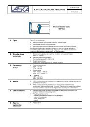
Sintered Hard MetalHIP-DensifiedThe HIP Process (hot isostatic pressing) consists of a special densification treatment.Applied after the sintering stage, this widely used process involves compacting, at very high temperature and pressure, of the carbidestructure. It yields an appreciable reduction in porosity, better strength properties and thus longer die life of press tool members.As can be seen from the diagrams and tables, both compressive and flexural strength are improved.For stamping die tooling, hard metal types of medium tungsten particle size, with a cobalt content of 9 to 12%, have been found succesfulin a wide field of applications.Tensile Strength of Tungsten – 6% Cobalt Carbide in the Sintered-Onlyversus HIP-Densified State, in Dependance of Cristallite Particle SizeTensile Strength of Tungsten – Cobalt Carbide in the Sintered-Only versusHIP-Densified State, in Dependance of total Cobalt Contenta) influence of crystallite size of hard metal phase(left: sintered only – right: sintered and HIP-treated)b) influence of cobalt content(left: sintered only – right: sintered and HIP-treated)Tungstencarbide- HV 30 -Hardness Flexural Strengthparticle Co N/mm 2size % befor after befor afterfinemediumcoarse3 1800 1200 17006 1650 1500 23009 1400 2000 26006 1600 2000 26009 1450 2350 270012 1300 no 2450 290015 1200 changes 2700 28506 1400 1900 22508 1350 2300 260010 1200 2650 2850Flexural Strength and HV30-Hardness of Tungsten-Cobalt Carbideswith/without HIP-Treatment and in Dependance of TungstenCarbideParticle Size and Cobalt Content.2·3102·7·2 °e 24subject to alterations
Carbide Punches – similar to DIN 9844 + DIN 9861270. 272. Cylindrical Head – Straight and Stepped271. 273. Conical Head – Straight and Stepped270. Shape A 271. Shape B272. Shape D 273. Shape CMaterial:Tungsten-Cobalt CarbideOrder No: Shape A = 270.9., Shape B = 271.9.Shape D = 272.9., Shape C = 273.9.Execution:Heads steel, brazed to shanks.Shanks precision ground.Dimensions:See DIN 9844 and DIN 9861 on pages E12, E13, E14, E15 and E 19.Other diameters and lengths on request.2·2371·8·4 °Delivery:270.Shape A from d 1 = 1,0 mm272.Shape D from d 1 = 1,5 mmOrdering Code (example):Carbide Punch = 272.Material: Tungsten-Cobalt Carbide = 272.9.d 1 = 6,0 mm = 272.9.0600.l 1 = 71 mm = 272.9.0600.071Order No = 272.9.0600.071subject to alterations e 25
2· 19131·2004·1 °e 26subject to alterations
Ball-Lock Punches2·17367·2002·1 °subject to alterations E 27
subject to alterations E 28
Ordering exampleBall-Lock PunchesNB:See table for standard dimensionsSpecial dimensions to order2 2 4 2 . 2 F 1 . 0 6 5 0 . 0 4 5 0 BPunch:22 without ejector pin27 with ejector pinPunch cuttinglength: l 1 Order No13 = 119 = 225 = 330 = 4special = XFormat: Slotlength P = 6,5 mmFormat:SlotwidthW = 4,5 mmVersion:Order Noblank = 0round = 1square = 2rectangular = 3slot = 4rectangle with radiused corners = 5pilot pin with tapered tip = 6pilot pin parabolic tip = 7special shapes = 9Type:Order Nolight = 2heavy = 3punch larger,light = 4punch larger,heavy = 5Diameter: d 2 Order No6 (light duty only) = 110 = 213 = 316 = 420 = 525 = 632 = 738 (light duty only) = 840 (heavy duty only) = 9OrderCodeLenght: l character50 = A56 = B63 = C71 = D80 = E90 = F100 = G110 = H125 = J140 = K150 = L175 = M200 = Nspecial = XOrderCodeAngle: character0° = A90° = B180° = C270° = Dspecial = XOrdering Code (Example):2242.2F1.0650.0450BAngle = 90° (B)Format: Slot, width W = 4,5 mm (0450)Format: Slot, length P = 6,5 mm (0650)Punch length: l 1 = 13 mm (1)Length: l = 90 mm (F)Diameter: d 2 = 10 mm (2)Type = light (2)Version: Slot (4)Punch: without ejector pin (22)E 29subject to alterations
Ball-Lock Punches, blank, light duty 2202.Ball-Lock Punches, stepped, light duty 2212.Material:HSShardened:Execution:62 ±2 HRCShaft and punch diameter fine ground.2202. ld 2 d 5 63 71 80 90 100 110 125 140 150 175 2006 6 • • • • •10 8 • • • • • • •13 8 • • • • • • • • • •16 8 • • • • • • • • • •20 8 • • • • • • • • • •25 8 • • • • • • • • • • •32 8 • • • • • • • • • •38 8 • • • • • • • • •2212. ld 2 d 5 P l 1 63 71 80 901006 6 1,6– 5,9 13* • • • • •10 8 1,6– 9,9 13* 19* • • • • •13 8 5,0–12,9 13 19 • • • • •16 8 8,0–15,9 13 19 25 • • • • •20 8 12,0–19,9 13 19 25 • • • • •25 8 16,0–24,9 13 19 25 • • • • •32 8 24,0–31,9 13 19 25 • • • •38 8 30,0–37,9 19 25 30 • • •* I 1 = 10 where P < 2,20Other lengths on request.Ordering example:see fold out page E 29.Other lengths on request.Ordering example:see fold out page E 29.E 30subject to alterations
2222. 2232. Ball-Lock Punches,2242. 2252. stepped, light duty2222. 2232.G = √ P2 +W 2G = √ 2 x P2222. 2232.G = PG = √ (P–1.0)2 +(W–1.0) 2 +1* For other radius options, see standardised special shapes, pages E 82 – E 83.Material:HSShardened:Execution:62 ±2 HRCShaft and punch shape fine ground.6 6 1,6 5,9 13* • • • • •10 8 1,6 9,9 13* 19* • • • • •13 8 4,5 12,9 13 19 • • • • •16 8 6,0 15,9 13 19 25 • • • • •20 8 8,0 19,9 13 19 25 • • • • •25 8 10,0 24,9 13 19 25 • • • • •32 8 12,5 31,9 13 19 25 • • • •38 8 14,0 37,9 19 25 30 • • •* I 1 = 10 where P or W < 2,20Other lengths on request.Ordering example:see fold out page E 29.subject to alterations e 31
Ball-Lock Punches, blank with ejector pin, light duty (replaces 2672.) 2702.Ball-Lock Punches, stepped with ejector pin, light duty(replaces 2682.) 2712.Material:HSShardened:Execution:Shaft fine ground.62 ±2 HRCMaterial:HSShardened:Execution:62 ±2 HRCShaft and punch diameter fine ground.2702.ld 2 d 5 63 71 80 90 1006 6 • • • • •10 8 • • • • •13 8 • • • • •16 8 • • • • •20 8 • • • • •25 8 • • • • •32 8 • • • •38 8 • • •2712. ld 2 d 5 P l 63 71 80 90 1006 6 1,6– 5,9 13* • • • • •10 8 1,6– 9,9 13* 19* • • • • •13 8 5,0–12,9 13 19 • • • • •16 8 8,0–15,9 13 19 25 • • • • •20 8 12,0–19,9 13 19 25 • • • • •25 8 16,0–24,9 13 19 25 • • • • •32 8 24,0–31,9 13 19 25 • • • •38 8 30,0–37,9 19 25 30 • • •* I 1 = 10 where P < 2,20Other lengths on requestOrdering example:see fold out page E 29.e 32Other lengths on request.Ordering example:see fold out page E 29.subject to alterations
2722. 2732.2742. 2752. Ball-Lock Punches,replaces 2682.stepped with ejector pin, light duty2722. 2732.G = √ P2 +W 2G = √ 2 3 P2742. 2752.G = P* For other radius options, see standardised special shapes, pages E 82 – E 83.G = √ (P–1.0)2 +(W–1.0) 2 +1Material:HSShardened:Execution:62 ±2 HRCShaft and punch shape fine ground.d 2 d 5 W min. G max. M l 1 63 71 80 90 1006 6 1,6 5,9 3 13* V V V V V10 8 1,6 9,9 5 13* 19* V V V V V13 8 4,5 12,9 5 13 19 V V V V V16 8 6,0 15,9 6 13 19 25 V V V V V20 8 8,0 19,9 6 13 19 25 V V V V V25 8 10,0 24,9 6 13 19 25 V V V V V32 8 12,5 31,9 8 13 19 25 V V V V38 8 14,0 37,9 8 19 25 30 V V V* I 1 = 10 where P or W < 2,20lOther lengths on request.2·17371·2002·1 °Ordering example:see fold out page E 29.subject to alterations e 33
Ball-Lock Punches, 2204.punch larger than shaft, light duty 2214.2204./2214.Material:HSShardened:62 ±2 HRCExecution:Shaft and punch diameter fine ground.2204. ld 2 d 5 P l 1 80 90 10013 8 32,0 19 30 V V V16 8 38,0 19 30 V V V20 8 40,0 19 30 V V V25 8 44,0 19 30 V V V32 8 50,0 19 30 V V V2214. ld 2 d 5 P l 1 80 90 10013 8 13,1 – 32,0 19 30 V V V16 8 16,1 – 38,0 19 30 V V V20 8 20,1 – 40,0 19 30 V V V25 8 25,1 – 44,0 19 30 V V V32 8 32,1 – 50,0 19 30 V V VOther lengths on request.Other lengths on request.Ordering example:see fold out page E 29.Ordering example:see fold out page E 29.2·17372·2002·1 °e 34subject to alterations
Ball-Lock Punches,2224. 2234. punch larger than shaft,2244. 2254. light duty2224. 2234.G = √ P2 +W 2G = √ 2 3 P2244. 2254.G = √ (P–1.0)2 +(W–1.0) 2 +1G = P* For other radius options, see standardised special shapes, pages E 82 – E 83.Material:HSShardened:Execution:62 ±2 HRCShaft and punch shape fine ground.d 2 d 5 W min. G max. l 1 80 90 10013 8 5,0 32,0 19 30 V V V16 8 6,5 38,0 19 30 V V V20 8 8,0 40,0 19 30 V V V25 8 10,0 44,0 19 30 V V V32 8 11,5 50,0 19 30 V V VlOther lengths on request.2·17373·2002·1 °Ordering example:see fold out page E 29.subject to alterations e 35
Ball-Lock Punches,punch larger than shaft, 2704.light duty with ejector pin 2714.2704./2714.Material:HSShardened:62 ±2 HRCExecution:Shaft and punch diameter fine ground.2704. ld 2 d 5 P l 1 80 90 10013 8 32,0 19 30 V V V16 8 38,0 19 30 V V V20 8 40,0 19 30 V V V25 8 44,0 19 30 V V V32 8 50,0 19 30 V V V2714. ld 2 d 5 P l 1 80 90 10013 8 13,1 – 32,0 19 30 V V V16 8 16,1 – 38,0 19 30 V V V20 8 20,1 – 38,0 19 30 V V V25 8 25,1 – 45,0 19 30 V V V32 8 32,1 – 50,0 19 30 V V VOther lengths on request.Other lengths on request.Ordering example:see fold out page E 29.Ordering example:see fold out page E 29.2·17374·2002·1 °e 36subject to alterations
Ball-Lock Punches,2724. 2734. punch larger than shaft,2744. 2754. light duty with ejector pin2724. 2734.G = √ P2 +W 2G = √ 2 3 PG = √ (P–1.0)2 +(W–1.0) 2 +12744. 2754.G = P* For other radius options, see standardised special shapes, pages E 82 – E 83.Material:HSShardened:Execution:62 ±2 HRCShaft and punch shape fine ground.d 2 d 5 W min. G max. l 1 80 90 10013 8 5,0 32,0 19 30 V V V16 8 6,5 38,0 19 30 V V V20 8 8,0 40,0 19 30 V V V25 8 10,0 44,0 19 30 V V V32 8 11,5 50,0 19 30 V V VlOther lengths on request.2·17375·2002·1 °Ordering example:see fold out page E 29.subject to alterations e 37
Ball-Lock Pilot Pins,with tapered tip, light duty 2262.2262.Material:HSShardened:Execution:62 ±2 HRCShaft and pilot pin fine ground.2262. ld 2 d 5 P l 1 N 71 80 90 100 110 125 140 15010 8 5,9‐– 9,9 19 8 V V V V V13 8 9,9 – 12,9 19 10 V V V V V V V16 8 12,9 – 15,9 25 15 V V V V V V V V20 8 15,9 – 19,9 25 20 V V V V V V V V25 8 19,9 – 24,9 25 25 V V V V V V V V32 8 24,9 – 31,9 25 30 V V V V V V V38 8 31,9 – 37,9 30 35 V V V V V V VOther lengths on request..Ordering example:see fold out page E 29.2·17376·2002·1 °e 38subject to alterations
Ball-Lock Pilot Pins,2272. with parabolic tip, light duty2272.Material:HSShardened:Execution:62 ±2 HRCShaft and pilot pin fine ground.„l“ length of pilot pin is without tipNote: The 2 mm length provides full guidancebefore the blanking punch contacts the sheet metal.PN≤ 10 mm 8 mm10,1 mm – 15 mm 12 mm> 15 mm 15 mm2272. ld 2 d 5 P l 1 50 56 63 71 80 90 1006 6 2,9 – 5,9 13 V V V V V V V10 8 5,9 – 9,9 19 V V V V V V V13 8 9,9 – 12,9 19 V V V V V V V16 8 12,9 – 15,9 25 V V V V V20 8 15,9 – 19,9 25 V V V V V25 8 19,9 – 24,9 25 V V V V V32 8 24,9 – 31,9 25 V V V V38 8 31,9 – 37,9 30 V V VOther lengths on request.2·17377·2002·1 °Ordering example:see fold out page E 29.subject to alterations e 39
Ball-Lock Punches, blank, heavy duty 2203.Ball-Lock Punches, stepped, heavy duty 2213.2203.Material:HSShardened:62 ±2 HRCExecution:Shaft fine ground.2213.Material:HSShardened:62 ±2 HRCExecution:Shaft and punch diameter fine ground.2203. ld 2 d 5 63 71 80 90 100 110 125 140 150 175 20010 10 V V V V V V V13 12 V V V V V V V V V V16 12 V V V V V V V V V V20 12 V V V V V V V V V V25 12 V V V V V V V V V V32 12 V V V V V V V V V V40 12 V V V V V V V V V2213. ld 2 d 5 P l 1 63 71 80 90 100 110 12510 10 1,6– 9,9 13* 19* V V V V V V V13 12 5,0–12,9 13 19 V V V V V V V16 12 8,0–15,9 13 19 25 V V V V V V V20 12 12,0–19,9 13 19 25 V V V V V V V25 12 16,0–24,9 13 19 25 V V V V V V32 12 24,0–31,9 13 19 25 V V V V V V40 12 30,0–39,9 19 25 30 V V V V VOther lengths on request.* l 1 = 10 where P < 2,20Other lengths on request.Ordering example:see fold out page E 29.Ordering example:see fold out page E 29.2·17378·2002·1 °e 40subject to alterations
2223. 2233. Ball-Lock Punches,2243. 2253. stepped, heavy duty2223. 2233.G = √ 2 3 PG = √ P2 +W 22243. 2253.G = PG = √ (P–1.0)2 +(W–1.0) 2 +1* For other radius options, see standardised special shapes, pages E 82 – E 83.Material:HSShardened:Execution:62 ±2 HRCShaft and punch shape fine ground.d 2 d 5 W min. G max. l 1 63 71 80 90 100 110 12510 10 1,6 9,9 13* 19* V V V V V V V13 12 4,5 12,9 13 19 V V V V V V V16 12 6,0 15,9 13 19 25 V V V V V V V20 12 8,0 19,9 13 19 25 V V V V V V V25 12 10,0 24,9 13 19 25 V V V V V V32 12 12,5 31,9 13 19 25 V V V V V V40 12 14,0 39,9 19 25 30 V V V V Vl*l 1 = 10 where P or W < 2,20Other lengths on request.2·17379·2002·1 °Ordering example:see fold out page E 29.subject to alterations e 41
Ball-Lock Punches, blank with ejector pin, heavy duty (replaces 2673.) 2703.Ball-Lock Punches, stepped with ejector pin,heavy duty (replaces 2683.) 2713.2703.Material:HSShardened:62 ±2 HRCExecution:Shaft fine ground.2713.Material:HSShardened:62 ±2 HRCExecution:Shaft and punch diameter fine ground.2703. ld 2 d 5 63 71 80 90 100 110 12510 10 V V V V V13 12 V V V V V V V16 12 V V V V V V V20 12 V V V V V V V25 12 V V V V V V32 12 V V V V V V40 12 V V V V V2713. ld 2 d 5 P l 1 63 71 80 90 100 110 12510 10 1,6– 9,9 13* 19* V V V V V13 12 5,0–12,9 13 19 V V V V V V V16 12 8,0–15,9 13 19 25 V V V V V V V20 12 12,0–19,9 13 19 25 V V V V V V V25 12 16,0–24,9 13 19 25 V V V V V V32 12 24,0–31,9 13 19 25 V V V V V V40 12 30,0–39,9 19 25 30 V V V V VOther lengths on request.* l 1 = 10 mm where < 2,20Other lengths on request.Ordering example:see fold out page E 29.Ordering example:see fold out page E 29.2·17380·2002·1 °e 42subject to alterations
2723. 2733. Ball-Lock Punches,2743. 2753. stepped with ejector pin,replaces 2683.heavy duty2723. 2733.G = √ 2 3 P2743. 2753.G = √ P2 +W 2* For other radius options,see standardisedspecial shapes, pagesE 82 – E 83.G = PG = √ (P–1.0)2 +(W–1.0) 2 +1Material:HSShardened:Execution:62 ±2 HRCShaft and punch shape fine ground.d 2 d 5 W min. G max. l 1 63 71 80 90 100 110 12510 10 1,6 9,9 13* 19* V V V V V13 12 4,5 12,9 13 19 V V V V V V V16 12 6,0 15,9 13 19 25 V V V V V V V20 12 8,0 19,9 13 19 25 V V V V V V V25 12 10,0 24,9 13 19 25 V V V V V V32 12 12,5 31,9 13 19 25 V V V V V V40 12 14,0 39,9 19 25 30 V V V V Vl* l 1 = 10 where P or W < 2,20Other lengths on request.2·17381·2002·1 °Ordering example:see fold out page E 29.subject to alterations e 43
Ball-Lock Punches, 2205.punch larger than shaft, heavy duty 2215.2205./2215.Material:HSShardened:62 ±2 HRCExecution:Shaft and punch diameter fine ground.2205. ld 2 d 5 P l 1 80 90 10013 12 32,0 19 30 V V V16 12 38,0 19 30 V V V20 12 40,0 19 30 V V V25 12 44,0 19 30 V V V32 12 50,0 19 30 V V V40 12 56,0 19 30 V V V2215. ld 2 d 5 P l 1 80 90 10013 12 13,1 – 32,0 19 30 V V V16 12 16,1 – 38,0 19 30 V V V20 12 20,1 – 40,0 19 30 V V V25 12 25,1 – 44,0 19 30 V V V32 12 32,1 – 50,0 19 30 V V V40 12 40,1 – 56,0 19 30 V V VOther lengths on request.Other lengths on request.Ordering example:see fold out page E 29.Ordering example:see fold out page E 29.2·17382·2002·1 °e 44subject to alterations
Ball-Lock Punches,2225. 2235. punch larger than shaft,2245. 2255. heavy duty2225. 2235.G = √ P2 +W 2G = √ 2 3 P2245. 2255.G = √ (P–1.0)2 +(W–1.0) 2 +1G = P* For other radius options, see standardised special shapes, pages E 82 – E 83.Material:HSShardened:Execution:62 ±2 HRCShaft and punch shape fine ground.d 2 d 5 W min. G max. l 1 80 90 10013 12 5,0 32,0 19 30 V V V16 12 6,5 38,0 19 30 V V V20 12 8,0 40,0 19 30 V V V25 12 10,0 44,0 19 30 V V V32 12 11,5 50,0 19 30 V V V40 12 14,0 56,0 19 30 V V VlOther lengths on request.2·17383·2002·1 °Ordering example:see fold out page E 29.subject to alterations e 45
Ball-Lock Punches,punch larger than shaft, 2705.heavy duty with ejector pin 2715.2705./2715.Material:HSShardened:62 ±2 HRCExecution:Shaft and punch diameter fine ground.2705. ld 2 d 5 P l 1 80 90 10013 12 32,0 19 30 V V V16 12 38,0 19 30 V V V20 12 40,0 19 30 V V V25 12 44,0 19 30 V V V32 12 50,0 19 30 V V V40 12 56,0 19 30 V V V2715. ld 2 d 5 P l 1 80 90 10013 12 13,1 – 32,0 19 30 V V V16 12 16,1 – 38,0 19 30 V V V20 12 20,1 – 40,0 19 30 V V V25 12 25,1 – 44,0 19 30 V V V32 12 32,1 – 50,0 19 30 V V V40 12 40,1 – 56,0 19 30 V V VOther lengths on request.Other lengths on request.Ordering example:see fold out page E 29.Ordering example:see fold out page E 29.2·17384·2002·1 °e 46subject to alterations
Ball-Lock Punches,2725. 2735. punch larger than shaft,2745. 2755. heavy duty with ejector pin2725. 2735.G = √ P2 +W 2G = √ 2 3 P2745. 2755.G = √ (P–1.0)2 +(W–1.0) 2 +1G = P* For other radius options, see standardised special shapes, pages E 82 – E 83.Material:HSShardened:Execution:62 ±2 HRCShaft and punch shape fine ground.d 2 d 5 W min. G max. l 1 80 90 10013 12 5,0 32,0 19 30 V V V16 12 6,5 38,0 19 30 V V V20 12 8,0 40,0 19 30 V V V25 12 10,0 44,0 19 30 V V V32 12 11,5 50,0 19 30 V V V40 12 14,0 56,0 19 30 V V VlOther lengths on request.2·17385·2002·1 °Ordering example:see fold out page E 29.subject to alterations e 47
Ball-Lock Pilot Pins,with tapered tip, heavy duty 2263.2263.Material:HSShardened:Execution:62 ±2 HRCShaft and pilot pin fine ground.2263. ld 2 d 5 P min. l 1 N 71 80 90 100 110 125 140 15010 10 5,9‐–‐ 9,9 19 8 V V V V V13 12 9,9 –‐12,9 19 10 V V V V V V V16 12 12,9 –‐15,9 25 15 V V V V V V V V20 12 15,9 –‐19,9 25 20 V V V V V V V V25 12 19,9 – 24,9 25 25 V V V V V V V32 12 24,9 – 31,9 25 30 V V V V V V V40 12 31,9 – 39,9 30 40 V V V V V V VOther lengths on request.Ordering example:see fold out page E 29.2·17386·2002·1 °e 48subject to alterations
Ball-Lock Pilot Pins,2273. with parabolic tip, heavy duty2273.Material:HSShardened:Execution:62 ±2 HRCShaft and pilot pin fine ground.„l“ length of pilot pin is without tipNote: The 2 mm length provides full guidancebefore the blanking punch contacts the sheet metal.PN≤ 10 mm 8 mm10,1 mm – 15 mm 12 mm> 15 mm 15 mm2273. ld 2 d 5 P l 1 63 71 80 90 100 110 12510 10 5,9 – 9,9 19 V V V V V13 12 9,9 – 12,9 19 V V V V V V V16 12 12,9 – 15,9 25 V V V V V V V20 12 15,9 – 19,9 25 V V V V V V V25 12 19,9 – 24,9 25 V V V V V V V32 12 24,9 – 31,9 25 V V V V V V40 12 31,9 – 39,9 30 V V V V VOther lengths on request.2·17387·2002·1 °Ordering example:see fold out page E 29.subject to alterations e 49
e 50subject to alterations
Precision PunchesISO2·17367·2002·1 °subject to alterations E 51
subject to alterations E 52
Ordering examplePrecision Punches ISO 8020NB:See table for standard dimensionsSpecial dimensions to order2241. 2 G 4 . 0 6 5 0 . 0 4 5 0 APunch:22 without ejector pin27 with ejector pinVersion:Order Noblank = 0round = 1square = 2rectangular = 3slot = 4rectangle with radiused corners = 5pilot pin with tapered tip = 6pilot pin parabolic tip = 7special shapes = 9Type:Order NoISO = 1Punch cuttinglength: l 1 Order No8 = 110 = 213 = 319 = 425 = 530 = 6special = xDiameter: d 1 Order No3 = 14 = 25 = 36 = 48 = 510 = 613 = 716 = 820 = 925 = 1032 = 11Format: Slotlength P = 6,5 mmOrder CodecharacterLenght: l50 = A56 = B63 = C71 = D80 = E90 = F100 = G110 = H120 = J125 = K140 = L150 = M200 = Nspecial = XFormat:SlotwidthW = 4,5 mmAngle:0° = A90° = B180° = C270° = Dspecial = XOrder CodecharacterOrdering Code (Example):2241.7G4.0650.0450AAngle = 0° (A)Format: Slot, width W = 4,5 mm (0450)Format: Slot, length P = 6,5 mm (0650)Punch length: l 1 = 13 mm (4)Length: l = 100 mm (G)Diameter: d 1 = 13 mm (7)Type = ISO (1)Version: Slot (4)Punch: without ejector pin (22)E 53subject to alterations
Precision Punches, ISO 8020 2201.Precision Punches, stepped, ISO 8020 2211.Material:HSSHardness: shaft 64±2 HRChead 52±5 HRCASP 23 – ASP 2023Hardness: shaft 64±2 HRChead 52±5 HRCOrdering example: 2201.6D.ASPDiameter d 1 =10Length =71(see fold out pages)Execution:Head hot upset-forged, shank andshoulder fine ground.Material:HSSHardness: shaft 64±2 HRCheadASP 23 – ASP 2023upon requestExecution:52±5 HRCHead hot upset-forged, shank, shoulderand cutting diameter fine ground.2201.ld 1 d 2 r T 71 80 90 100 120 150 2003 5 0,25 3 V V V V V4 6 3 V V V V V5 8 0,3 5 V V V V V6 9 5 V V V V V8 11 5 V V V V V10 13 5 V V V V V V13 16 0,4 5 V V V V V V16 19 5 V V V V V V V20 23 5 V V V V V V V25 28 5 V V V V V V V32 35 5 V V V V V V V2211.ld 1 d 2 P l 1 r T 71 80 90 100 1203 5 0,8– 2,9 8 10 0,25 3 V V V V V4 6 1,0– 3,9 8 13 3 V V V V V5 8 1,5– 4,9 13 19 0,3 5 V V V V V6 9 1,6– 5,9 13 19 5 V V V V V8 11 2,5– 7,9 19 25 5 V V V V V10 13 4,0– 9,9 19 25 5 V V V V V13 16 5,0–12,9 19 25 0,4 5 V V V V V16 19 8,0–15,9 19 25 5 V V V V V20 23 12,0–19,9 19 25 5 V V V V V25 28 16,5–24,9 19 25 5 V V V V V32 35 20,0–31,9 25 30 5 V V V V VOrdering example:see fold out page E 53.Ordering example:see fold out page E 53.E 54subject to alterations
2221. 2231. Precision Punches,2241. 2251. stepped, ISO 80202221. 2231.G = √ P2 +W 2G = √ 2 x P2241. 2251.G = PG = √ (P–1.0)2 +(W-1.0) 2 +1* For other radius options, see standardised special shapes, pages E 82 – E 83.Material:HSSHardness: shaft 64±2 HRChead 52±5 HRCExecution:Punch head, hot swaged, seating, shaftand punch shape fine ground.The anti-rotation surface parallel to P = 0°as standard.ASP 23 – ASP 2023upon requestld 1 d 2 W min. G max. l 1 r T 71 80 90 100 1203 5 0,5– 2,9 8 10 0,25 3 V V V V V4 6 0,8– 3,9 8 13 3 V V V V V5 8 1,0– 4,9 13 19 0,3 5 V V V V V6 9 1,6– 5,9 13 19 5 V V V V V8 11 2,0– 7,9 19 25 5 V V V V V10 13 3,5– 9,9 19 25 5 V V V V V13 16 4,5–12,9 19 25 0,4 5 V V V V V16 19 6,0–15,9 19 25 5 V V V V V20 23 8,0–19,9 19 25 5 V V V V V25 28 10,0–24,9 19 25 5 V V V V V32 35 10,0–31,9 25 30 5 V V V V VOrdering example:see fold out page E 53.subject to alterations e 55
Precision Punches with ejector pin, ISO 8020 (replaces 2671.) 2701.Precision Punches stepped,with ejector pin ISO 8020 (replaces 2681.) 2711.2701.Material:HSSHardness: shaft 64±2 HRChead 52±5 HRCExecution:Head hot upset-forged, shank and shoulderfine ground.2711.Material:HSSHardness: shaft 64±2 HRChead 52±5 HRCExecution:Head hot upset-forged, shank, shoulderand cutting diameter fine ground.2701.ld 1 d 2 r T 71 80 90 100 1205 8 0,3 5 ● ● ● ● ●6 9 5 ● ● ● ● ●8 11 5 ● ● ● ● ●10 13 5 ● ● ● ● ●13 16 0,4 5 ● ● ● ● ●16 19 5 ● ● ● ● ●20 23 5 ● ● ● ● ●25 28 5 ● ● ● ● ●32 35 5 ● ● ● ● ●2711.ld 1 d 2 P l 1 r T 71 80 90 100 1205 8 1,6– 4,9 13 19 0,3 3 V V V V V6 9 2,5– 5,9 13 19 3 V V V V V8 11 2,5– 7,9 19 25 5 V V V V V10 13 4,0– 9,9 19 25 5 V V V V V13 16 5,0–12,9 19 25 0,4 5 V V V V V16 19 8,0–15,9 19 25 5 V V V V V20 23 12,0–19,9 19 25 5 V V V V V25 28 16,5–24,9 19 25 5 V V V V V32 35 20,0–31,9 25 30 5 V V V V VOrdering example:see fold out page E 53.e 56Ordering example:see fold out page E 53.subject to alterations
2721. 2731. Precision Punches, stepped,2741. 2751. with ejector pin ISO 8020replaces 2681.2721. 2731.G = √ P2 +W 2G = √ 2 3 P2741. 2751.G = PG = √ (P–1.0)2 +(W–1.0) 2 +1* For other radius options, see standardised special shapes, pages E 82 – E 83.Material:HSSHardness: shaft 64±2 HRChead 52±5 HRCExecution:Punch head, hot swaged, seating, shaftand punch shape fine ground.The anti-rotation surface parallel to P = 0°as standard.ld 1 d 2 W min G max. l 1 r T 71 80 90 100 1205 8 1,6– 4,9 13 19 0,3 5 ● ● ● ● ●6 9 2,5– 5,9 13 19 5 ● ● ● ● ●8 11 2,5– 7,9 19 25 5 ● ● ● ● ●10 13 4,0– 9,9 19 25 5 ● ● ● ● ●13 16 5,0–12,9 19 25 0,4 5 ● ● ● ● ●16 19 8,0–15,9 19 25 5 ● ● ● ● ●20 23 12,0–19,9 19 25 5 ● ● ● ● ●25 28 16,5–24,9 19 25 5 ● ● ● ● ●32 35 20,0–31,9 25 30 5 ● ● ● ● ●2·17399·2002· 1 °Ordering example:see fold out page E 53.subject to alterations e 57
Pilot Pins with tapered tip,ISO 8020 2261.2261.Material:HSSHardness: shaft 64±2 HRChead 52±5 HRCExecution:Punch head hot swaged, seating, shaft and pilot fine ground.2261.ld 1 d 2 T P l 1 N 63 71 80 90 100 110 125 1405 8 5 1,0– 4,9 13 4 V V6 9 5 1,6– 5,9 13 5 V V V8 11 5 2,5– 7,9 13 6 V V V V10 13 5 4,0– 9,9 13 19 8 V V V V V V13 16 5 5,0–12,9 13 19 10 V V V V V V V16 19 5 8,0–15,9 13 19 25 15 V V V V V V V20 23 5 12,0–19,9 13 19 25 20 V V V V V V V25 28 5 16,5–24,9 13 19 25 25 V V V V V V V32 35 5 20,0–31,9 19 25 30 V V V V V VOrdering example:see fold out page E 53.2·17400·2002·1 °e 58subject to alterations
Pilot Pins with parabolic tip,2271. ISO 80202271.Material:HSSHardness: shaft 64±2 HRChead 52±5 HRCExecution:Punch head hot swaged, seating, shaft and pilot fine ground.„l“ length of pilot pin is without tipNote: The 2 mm length provides full guidancebefore the blanking punch contacts the sheet metal.PN≤ 10 mm 8 mm10,1 mm – 15 mm 12 mm> 15 mm 15 mm2271.ld 1 d 2 T P l 1 50 56 63 71 80 90 1005 8 5 1,0– 4,9 10 13 V V V V6 9 5 1,6– 5,9 10 13 V V V V V8 11 5 2,5– 7,9 10 13 V V V V V10 13 5 4,0– 9,9 10 13 19 V V V V V V V13 16 5 5,0–12,9 10 13 19 V V V V V V V16 19 5 8,0–15,9 13 19 V V V V V V V20 23 5 12,0–19,9 13 19 V V V V V V25 28 5 16,5–24,9 13 19 V V V V V V32 35 5 20,0–31,9 19 V V V V2·17401·2002·1 °Ordering example:see fold out page E 53.subject to alterations e 59
Pilot Unitsto Daimler Standard 2276.2276.Description:The pilot unit provides exact positioning of sheet metal parts.There are 2 sizes.The pilot unit 10 can used for a hole diameter of 5 ~ 10 mm andis available as a finished item, 9.8 mm diameter. Smaller diametershave to be ground by the tool making department.The pilot unit 16 is used for diameter 10 - 16 mm and is available asa blank, 16 mm diameter.Material:The pilot unit consists of:Pilot pin, Casing, Compression spring, Parallel dowel pin.2276.Spring force in daNOrder No d d 1 d 2 d 3 d 4 d 5 h h 1 h 2 l 1 l 2 l preloaded compressed2276.1. 9,8 10 10 18 18 15 28 25 12 47,5 39,3 63,2 4,9 6,22276.2. 16 16 16 24 30 26 28 25 12 54,5 46,3 72,5 4,8 5,6Ordering example: 2 2 7 6 . 1 . A . 0 9 8 0Diameter dLength lA = 63,2 mmB = 72,5 mmDiameter d 11 = 10 mm2 = 16 mmDaimler standardPilot pin2· 17402·2002·1 °e 60subject to alterations
Precision Matrixes2·17367·2002·1 °subject to alterationsE 61
subject to alterations E 62
Ordering examplePrecision MatrixesNB:See table for standard dimensionsSpecial dimensions to order2 6 4 6 . 10 F 6 . 1 3 5 0 . 0 6 5 0 A 2Matrixes:26 matrixesVersion:Order Noblank (pilot hole bore) = 0round = 1square = 2rectangular = 3slot = 4rectangle with radiused corners = 5special shapes = 9Type:Order Noautomotive standard = 5without shoulder ISO 8977 = 6with shoulder ISO 8977 = 7Ordering Code (Example):Shape cuttinglenght: l Order No2 = 13 = 24 = 35 = 46 = 58 = 610 = 712 = 8special = XDiameter: d 2 Order No5 = 16 = 28 = 310 = 413 = 516 = 620 = 722 = 825 = 932 = 1038 = 1140 = 1245 = 1350 = 1456 = 1563 = 1671 = 1776 = 1886 = 1990 = 20100 = 21Format: SlotlenghtP = 13,5 mmOrder CodeLength: l1 character13 = A16 = B20 = C22 = D25 = E28 = F30 = G32 = H35 = J40 = Kspecial = XFormat:Slot widthW = 6,5 mmAngle:0° = A90° = B180° = C270° = Dspecial = XOrder CodecharacterAnti-rotation Orderelement: Nopin Ø 3 = 1pin Ø 4 = 2pin Ø 6 = 3polished surface(continuous) = 4polished surface,top, 14 mm = 5polished surface,bottom, 14 mm = 6special = X2646.10F6.1350.0650A2Anti-rotation element = Pin Ø4 (2)Angle = 0° (A)Format: Slot, width W = 6,5 mm (0650)Format: Slot, length P = 13,5 mm (1350)Shape cutting length: l = 8 mm (6)Lenght: l 1 = 28 mm (F)Diameter: d 2 = 32 mm (10)Type = without shoulder ISO 8977 (6)Version: Slot (4)Matrixes:Matrixes (26)E 63subject to alterations
2· 17412·2002·1 °E 64subject to alterations
2606. Precision Matrixes2616. without shoulder, cylindricalreplaces 2603. ISO 8977Material:HSShardened:Execution:62 ±2 HRCDiameter d 2 , starting lead and face surfacesground.Diameter P is a bored pilot hole for wireEDM.2606.Material:HSShardened:Execution:62 ±2 HRCDiameter d 2 , starting lead and face surfacesground.2616.2606.l 1d 2 d 4 P l 16 20 22 25 28 30 32 35 405 2,8 0,8 2 V V V V V V V V6 3,5 1,0 3 V V V V V V V V8 4,0 1,0 4 V V V V V V V V10 5,8 1,0 4 8 V V V V V V V V13 8,0 1,2 5 8 V V V V V V V16 9,5 1,2 5 8 V V V V V V V20 12,0 1,5 8 12 V V V V V V V22 15,0 1,5 8 12 V V V V V V V25 17,3 1,5 8 12 V V V V V V V32 20,7 1,5 8 12 V V V V V V V40 27,7 1,5 8 12 V V V V V50 37,0 1,5 8 12 V V V V V V2616.d 2 d 4 P l 16 20 22 25 28 30 32 35 405 2,8 1,0– 2,4 2 V V V V V V V V6 3,5 1,6– 3,0 3 V V V V V V V V8 4,0 2,0– 3,5 4 V V V V V V V V10 5,8 2,5– 5,0 4 8 V V V V V V V V13 8,0 4,0– 7,0 5 8 V V V V V V V16 9,5 6,0– 9,0 5 8 V V V V V V V20 12,0 8,0–11,0 8 12 V V V V V V V22 15,0 9,0–14,0 8 12 V V V V V V V25 17,3 10,7–16,0 8 12 V V V V V V V32 20,7 15,0–20,0 8 12 V V V V V V V40 27,7 19,0–27,0 8 12 V V V V V50 37,0 26,0–36,0 8 12 V V V V V Vl 12·17409·2002·1 °Other lengths on requestOrdering example:see fold out page E 63.Ordering example:see fold out page E 63.subject to alterations e 65
Precision Matrixeswithout shoulder, cylindrical 2626. 2636.ISO 8977 2646. 2656.2626. 2636.G = √ P2 +W 2G = √ 2 X P2646. 2656.G = √ (P–1.0)2 +(W–1.0) 2 +1G = P* For other radius options, see standardised special shapes, pages E 82 – E 83.Material:HSShardened:62 ±2 HRCAnti-rotation element,see page E 67Execution:Diameter d 2 , and end faces ground.l 1d 2 d 4 W min. G max. l 16 20 22 25 28 30 32 35 4010 5,8 1,2 5,0 4 8 V V V V V V V V13 8,0 2,0 7,0 5 8 V V V V V V V16 9,5 2,4 9,0 5 8 V V V V V V V20 12,0 3,2 11,0 8 12 V V V V V V V22 15,0 4,0 14,0 8 12 V V V V V V V25 17,3 4,8 16,0 8 12 V V V V V V V32 20,7 5,5 20,0 8 12 V V V V V V V40 27,7 6,4 27,0 8 12 V V V V V50 37,0 9,0 36,0 8 12 V V V V V Vother lengths on requestOrdering example:see fold out page E 63.e 66subject to alterations
Precision Matrixes without shoulder,cylindrical , ISO 8977Anti-rotation elementsanti-rotation element 1 Pin [3 anti-rotation element 2 Pin [4 anti-rotation element 3d 2 Fd 2 F10 510 613 6,513 7,216 816 820 1020 1022 1122 1125 12,525 12,532 1632 1640 2040 2050 2550 25Pin [6d 2 F10 713 8,216 920 1122 1225 13,532 1640 2050 25anti-rotation element 4 anti-rotation element 5 anti-rotation element 6d 2 Fd 2 F10 410 413 5,513 5,516 716 720 8,520 8,522 9,522 9,525 1125 1132 1432 1440 1840 1850 2350 23d 2 F10 413 5,516 720 8,522 9,525 1132 1440 1850 232·17411·2002·1 °Ordering example:see fold out page E 63.subject to alterations e 67
2· 19136·2003·1 °e 68subject to alterations
2607. Precision Matrixes with shoulder,2617. cylindrical ISO 8977replaces 2613.Material:HSShardened:62 ±2 HRC2607.Execution:Diameter d 2 , and end faces ground.Diameter P is a bored pilot hole for wireEDM.Material:HSShardened:62 ±2 HRC2617.Execution:Diameter d 2 , and end faces ground.2607. l 1d 2 d 3 d 4 P l 16 20 22 25 28 30 32 355 8 2,8 0,8 2 V V V V V V V V6 9 3,5 1,0 3 V V V V V V V V8 11 4,0 1,0 4 V V V V V V V V10 13 5,8 1,0 4 8 V V V V V V V V13 16 8,0 1,2 5 8 V V V V V V V16 19 9,5 1,2 5 8 V V V V V V V20 23 12,0 1,5 8 12 V V V V V V V22 25 15,0 1,5 8 12 V V V V V V V25 28 17,3 1,5 8 12 V V V V V V V32 35 20,7 1,5 8 12 V V V V V V V40 43 27,7 1,5 8 12 V V V V V V V50 53 37,0 1,5 8 12 V V V V V V V2617. l 1d 2 d 3 d 4 P l 16 20 22 25 28 30 32 355 8 2,8 1,0– 2,4 2 V V V V V V V V6 9 3,5 1,6– 3,0 3 V V V V V V V V8 11 4,0 2,0– 3,5 4 V V V V V V V V10 13 5,8 2,5– 5,0 4 8 V V V V V V V V13 16 8,0 4,0– 7,0 5 8 V V V V V V V16 19 9,5 6,0– 9,0 5 8 V V V V V V V20 23 12,0 8,0–11,0 8 12 V V V V V V V22 25 15,0 9,0–14,0 8 12 V V V V V V V25 28 17,3 10,7–16,0 8 12 V V V V V V V32 35 20,7 15,0–20,0 8 12 V V V V V V V40 43 27,7 19,0–27,0 8 12 V V V V V V V50 53 37,0 26,0–36,0 8 12 V V V V V V VOther lengths on request.Other lengths on request.2·17413·2002·1 °Ordering example:see fold out page E 63.Ordering example:see fold out page E 63.subject to alterations e 69
Precision Matrixes with shoulder, 2627. 2637.cylindrical ISO 8977 2647. 2657.2627. 2637.G = √ P2 +W 2G = √ 2 3 P2647. 2657.G = √ (P–1.0)2 +(W–1.0) 2 +1G = P* For other radius options, see standardised special shapes, pages E 82 – E 83.Material:HSShardened:Execution:62 ±2 HRCDiameter d 2 , and end faces ground.Anti-rotation element,see page E 71d 2 d 3 d 4 W min. G max. l 16 20 22 25 28 30 32 358 11 4,0 1,2 3,5 4 V V V V V V V V10 13 5,8 1,2 5,0 4 8 V V V V V V V V13 16 8,0 2,0 7,0 5 8 V V V V V V V16 19 9,5 2,4 9,0 5 8 V V V V V V V20 23 12,0 3,2 11,0 8 12 V V V V V V V22 25 15,0 4,0 14,0 8 12 V V V V V V V25 28 17,3 4,8 16,0 8 12 V V V V V V V32 35 20,7 5,5 20,0 8 12 V V V V V V V40 43 27,7 6,4 27,0 8 12 V V V V V V V50 53 37,0 6,4 36,0 8 12 V V V V V V Vl 1Other lengths on request.Ordering example:see fold out page E 63.2·17414·2002·1 °e 70subject to alterations
Precision Matrixes with shoulder,cylindrical, ISO 8977Anti-rotation elementsAnti-rotation element 1 Pin [3 Anti-rotation element 2 Pin [4 Anti-rotation element 3d 2 Fd 2 F8 5,58 610 6,510 713 813 8,516 9,516 1020 11,520 1222 12,522 1325 1425 14,532 17,532 1840 21,540 2250 26,550 27Pin [6d 2 F8 710 813 9,516 1120 1322 1425 15,532 1940 2350 28Anti-rotation element 42·17415·2002·1 °Ordering example:see fold out page E 63.subject to alterations e 71
Matrixes without shoulder, 2605.automotive standard 2615.2605.Material:HSShardened:62±2 HRCExecution:Diameter d 2 , and end faces ground.Diameter P is a bored pilot hole for wireEDM.2615.Material:HSShardened:62±2 HRCExecution:Diameter d 2 , and end faces ground.2605. l 1d 2 P 13 16 20 22 25 28 30 32 35 4010 0,8 V V V V V V V V V13 0,8 V V V V V V V V V16 1,5 V V V V V V V20 2,4 V V V V V V V22 3,0 V V V V V V V25 3,0 V V V V V V V32 3,0 V V V V V V V38 3,0 V V V V V V V V40 3,0 V V V V V V V45 3,0 V V V V V V V50 3,0 V V V V V V V56 3,0 V V V V V V V63 3,0 V V V V V V V71 3,0 V V V V V V V76 3,0 V V V V V V86 3,0 V V V V V V90 3,0 V V V V V V100 3,0 V V V V V VOther lengths on request2615. l 1d 2 P l 13 16 20 22 25 28 30 32 35 4010 1,6 – 6,8 3 4 5 V V V V V V V V V13 3,0 – 8,8 3 5 8 V V V V V V V V V16 7,4 –10,8 3 5 8 V V V V V V V20 9,5 –13,6 3 5 10 V V V V V V V22 10,5 –15,0 3 6 10 V V V V V V V25 12,0 –17,0 3 6 10 V V V V V V V32 16,0 –22,0 3 6 12 V V V V V V V38 18,0 –27,0 3 8 12 V V V V V V V V40 18,0 –27,0 3 8 12 V V V V V V V45 18,0 –35,0 3 8 12 V V V V V V V50 18,0 –40,0 3 8 12 V V V V V V V56 18,0 –45,0 3 8 12 V V V V V V V63 18,0 –50,0 3 8 12 V V V V V V V71 18,0 –56,0 3 8 12 V V V V V V V76 25,0 –60,0 3 8 12 V V V V V V86 25,0 –66,0 3 8 12 V V V V V V90 32,0 –70,0 3 8 12 V V V V V V100 32,0 –78,0 3 8 12 V V V V V VOther lengths on requestOrdering example: see fold out page E 63. Ordering example: see fold out page E 63.2·17416·2002·1 °e 72subject to alterations
2625. 2635. Matrixes without shoulder,2645. 2655. automotive standard2625. 2635.G = √ P2 +W 2G = √ 2 3 P G = P2645. 2655.G = √ (P–1.0)2 +(W–1.0) 2 +1* For other radius options, see standardised special shapes, pages E 82 – E 83.Anti-rotation element 3Pin [6d 2 F10 713 8,216 920 1122 1225 13,532 1638 1940 2045 22,550 2556 2863 31,571 35,576 3885 42,590 45100 50Material:HSShardened:Execution:62±2 HRCDiameter d 2 , and end faces ground.2·17417·2002·1 °d 2 W min. G max. l 13 16 20 22 25 28 30 32 35 4010 1,3 – 6,8 3 4 5 V V V V V V V V V13 1,9 – 8,8 3 5 8 V V V V V V V V V16 1,9 – 10,8 3 5 8 V V V V V V V20 1,9 – 13,6 3 5 10 V V V V V V V22 1,9 – 15,0 3 6 10 V V V V V V V25 1,9 – 17,0 3 6 10 V V V V V V V32 1,9 – 22,0 3 6 12 V V V V V V V38 1,9 – 27,0 3 8 12 V V V V V V V V40 1,9 – 27,0 3 8 12 V V V V V V V45 2,4– 35,0 3 8 12 V V V V V V V50 4,0 – 40,0 3 8 12 V V V V V V V56 4,0 – 45,0 3 8 12 V V V V V V V63 4,0 – 50,0 3 8 12 V V V V V V V71 4,0 – 56,0 3 8 12 V V V V V V V76 5,6 – 60,0 3 8 12 V V V V V V86 5,6 – 66,0 3 8 12 V V V V V V90 5,6 – 70,0 3 8 12 V V V V V V100 5,6 – 78,0 3 8 12 V V V V V VOther lengths on requestOrdering example: see fold out page E 63.l 1subject to alterations e 73
Precision Guide Bushes for PunchesDIN 9845, Shape C 262.ISO 8978 2621.Material:262.Case hardened steelOrder No. 262.1.Hardness 740 ± 40 HV 102621.WS, hardenedOrder No 2621.1.Hardness HRC 60 ± 2Execution:Diameters d 1 , d 2 and starting lead ground.Description of FIBRO materials for die components:pages E 10 – E 11.262. Shape C DIN 98452621. ISO 8978262.Diameterd 1 steps d 2 t l 1 r0,5– 1,0 0,1 5 0,01 9 11,1– 2,0 6 122,1– 3,0 73,1– 4,0 84,1– 5,0 10 165,1– 6,0 12 0,02 1,56,1– 8,0 15 208,1–10,0 18 210,1–12,0 22 2812,1–15,0 2615,1–18,0 0,5 30 362621.Diameterd 1 steps d 2 t l 1 r1,0 – 2,4 0,1 5 8 11,6 – 3,0 6 12,5 12,0 – 3,5 8 12,5 1,53,0 – 5,0 10 16 24,0 – 7,2 13 16 26,0 – 8,8 16 20 27,5 –11,3 20 20 2,511,0 –16,6 25 25 2,515,0 –20,0 0,5 32 25 418,0 –27,0 40 32 426,0 –36,0 50 40 4Other diameters on request.Ordering Code (example):Guide Bush for punches DIN 9845 = 262.Material case hardened steel = 1.d 1 = Ø 2,4 mm = 0240.l 1 = 12 mm = 012Order No = 262.1.0240.012e 74Ordering Code (example):Guide Bush for punches ISO 8978 = 2621.Material WS = 1.d 1 = Ø 2,0 mm = 0200.d 2 = Ø 6 mm = 0600Order No = 2621.1.0200.0600subject to alterations2·2373·7·4 °
Precision Matrixes260. with and without collar DIN 9845261. Shape A, Shape BMaterial:HSSOrder No: Shape A = 260.3.Shape B = 261.3.Hardness: 62 ± 2 HRC260. Shape ADescription of FIBRO materials fordie components: pages E 10 – E 11.Execution:Diameters d 1 and d 2 precision ground;face surface ground.261. Shape B260.Diameter short longd 1 steps d 2 d 4 l 1 l 2 l 1 l 20,5– 1,0 0,1 5 d +0,3 1 20 18 – –1,1– 2,0 6 17 28 252,1– 3,0 7 d +0,5 13,1– 4,0 84,1 –5,0 10 d +0,7 1 16 245,1– 6,0 126,1– 8,0 158,1–10,0 18 d +1 110,1–12,0 22 15 2312,1–15,0 2615,5–18,0 0,5 30 – –261.Diameter short longd 1 steps d 2 d 3 d 4 l 1 l 2 l 3 l 1 l 2 l 30,5– 1,0 0,1 5 7 d +0,3 1 20 18 16 – – –1,1– 2,0 6 8 17 28 25 242,1– 3,0 7 9 d +0,5 13,1– 4,0 8 104,1 –5,0 10 12 d +0,7 1 16 245,1– 6,0 12 146,1– 8,0 15 178,1–10,0 18 20 d +1 110,1–12,0 22 24 15 2312,1–15,0 26 2815,5–18,0 0,5 30 32 – – –2·2374·8·4 °Other diameters on request.Ordering Code (example):Matrix = 261.2.0220.028Material HSS = 261.3.0220.028d 1 = Ø 2,20 mm = 261.3.0220.028l 1 = 28 mm = 261.3.0220.028Order No = 261.3.0220.028subject to alterations e 75
Precision Matrixeswith and without collar 2602.cylindrical 2612.2602.Classified ShapeWith startingholes forwire-EDM asper 2601.page E 77.*d 1 = size over corners2612.Material:HSSOrder No.: 2602. o. 2612.3.Hardness: 64±2 HRCExecution:Diameters d 2 precision ground;face surfaces ground.Key flats parallel with Aunless otherwise specified.*d 1 = size over corners2602.Size over cornersd 1 , d 5 d 2 L F 16 19 22 25 28 321,8 – 3,2 8 3 1,0 ● ● ● ● ● ●2,0 – 5,0 10 ● ● ● ● ● ●3,0 – 7,0 13 1,5 ● ● ● ● ● ●5,0 – 8,0 16 5 ● ● ● ● ● ●7,0 – 11,0 20 ● ● ● ● ● ●11,0 – 16,0 25 2,5 ● ● ● ● ● ●16,0 – 19,0 32 7 ● ● ● ● ● ●19,0 – 28,0 40 ● ● ● ● ● ●L 12612.Size over cornersd 1 , d 5 d 2 d 3 L 16 19 22 25 28 321,8 – 3,2 8 11 3 ● ● ● ● ● ●2,0 – 5,0 10 13 ● ● ● ● ● ●3,0 – 7,0 13 16 ● ● ● ● ● ●5,0 – 8,0 16 19 5 ● ● ● ● ● ●7,0 – 11,0 20 23 ● ● ● ● ● ●11,0 – 16,0 25 28 ● ● ● ● ● ●16,0 – 19,0 32 35 7 ● ● ● ● ● ●19,0 – 28,0 40 43 ● ● ● ● ● ●L 1Ordering code (example):Matrix = 2602.Material HSS = 2602.3.d 2 = 16 mm = 2602.2.016.L 1 = 32 mm = 2602.2.016.032.Shape 2 = 2602.2.016.032.2.a = 3,96 mm = 2602.2.016.032.2.0396.b = 5,16 mm = 2602.2.016.032.2.0396.0516Order No = 2602.3.016.032.2.0396.0516Ordering code (example):Matrix = 2612.Material HSS = 2612.3.d 2 = 16 mm = 2612.2.016.L 1 = 28 mm = 2612.2.016.028.Shape 2 = 2612.2.016.028.2.a = 3,96 mm = 2612.2.016.028.2.0396.b = 5,16 mm = 2612.2.016.028.2.0396.0516Order No = 2612.3.016.028.2.0396.05162·10896·7·4 °e 76subject to alterations
Precision Matrixes2601. with and without collar2611. conicalClassified shapes2601.*d1 = size over corners* Shape 0 = with starting hole for wirecutMaterial:HSOrder No.: 2601. o. 2611.3.Hardness: 64 ± 2 HRC2611.*d 1 = size over cornersExecution:Diameters d 2 precision ground;face surfaces ground.Key flats parallel with Aunless otherwise specified.2601.Size over corners L 1d 1 , d 5 d 2 d 4 F 16 19 22 25 28 321,8– 3,2 8 1,0 1,0 ● ● ● ● ● ●2,0– 5,0 10 ● ● ● ● ● ●3,0– 7,0 13 1,5 1,5 ● ● ● ● ● ●5,0– 8,0 16 ● ● ● ● ● ●7,0–11,0 20 ● ● ● ● ● ●11,0–16,0 25 2,5 2,5 ● ● ● ● ● ●16,0–19,0 32 ● ● ● ● ● ●19,0–28,0 40 ● ● ● ● ● ●2611.Size over corners L 1d 1 , d 5 d 2 d 3 d 4 16 19 22 25 28 321,8– 3,2 8 11 1,0 ● ● ● ● ● ●2,0– 5,0 10 13 ● ● ● ● ● ●3,0– 7,0 13 16 1,5 ● ● ● ● ● ●5,0– 8,0 16 19 ● ● ● ● ● ●7,0–11,0 20 23 ● ● ● ● ● ●11,0–16,0 25 28 2,5 ● ● ● ● ● ●16,0–19,0 32 35 ● ● ● ● ● ●19,0–28,0 40 43 ● ● ● ● ● ●2·10895·7·3 °Ordering Code (example):Matrix = 2601.2.016.032.2.0396.0516.Material HSS = 2601.3.016.032.2.0396.0516.d 2 = 16 mm = 2601.2.016.032.2.0396.0516.L 1 = 32 mm = 2601.2.016.032.2.0396.0516.Shape 2 = 2601.2.016.032.2.0396.0516.a = 3,96 mm = 2601.2.016.032.2.0396.0516.b = 5,16 mm = 2601.2.016.032.2.0396.0516Order No = 2601.3.016.032.2.0396.0516Ordering Code (example):Matrix = 2611.2.016.032.2.0396.0516.Material HSS = 2611.3.016.032.2.0396.0516.d 2 = 16 mm = 2611.2.016.032.2.0396.0516.L 1 = 32 mm = 2611.2.016.032.2.0396.0516.Shape 2 = 2611.2.016.032.2.0396.0516.a = 3,96 mm = 2611.2.016.032.2.0396.0516.b = 5,16 mm = 2611.2.016.032.2.0396.0516Order No = 2611.3.016.032.2.0396.0516subject to alterations e 77
2· 19151·2003·1 °e 78subject to alterations
StandardisedSpecial Shapes2·17367·2002·1 °subject to alterations E 79
subject to alterations E 80
Ordering examplesSpecial shapesPunches/Cutting bushes2 2 9 2 . . F 2 4 . . .NB:All the parametersmust be given forspecial shapes!Punch:22 without ejector pinSpecial shape F 24View PunchSpecial shapeType:Order NoISO 8020 = 1ball-lock, light duty = 2ball-lock, heavy duty = 3ball-lock, larger cuttingedge,light duty = 4ball-lock, larger cuttingedge, heavy duty = 5You will find diametersand lengths on the pagesof punches you haveselected.2 6 9 5 . . F 2 4 . . .NB:All the parametersmust be given forspecial shapes!MatrixesSpecial shape F 24Special shapeType:OrderNoautomotive = 5without shoulder ISO 8977 = 6with shoulder ISO 8977 = 7You will find diametersand lengths on the pagesof cutting bushes you haveselected.View MatrixE 81subject to alterations
Standardised special shapes2· 17795·2002·1 °E 82subject to alterations
Standardised special shapessubject to alterations e 83
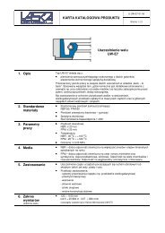
Dynamic Strippers (DAE) 2618.Mounting example:Mounting example:2618.Punchd 1 Matrixd 5 d 6 d 8 l M Gradation = 0,1 d 2 d 37 11 5 19,95 M6 3,0 – 4,0 8 118 12 6 M8 4,1 – 5,0 9 129 13 7 M8 5,1 – 6,0 10 1310 14 8 M10 6,1 – 7,0 11 1411 15 9 M10 7,1 – 8,0 12 15Ordering-code (example):Dynamic Stripping Element (DAE) = 2618.d 5 = [ 7 mm = 2618.07.l = 19,95 mm = 2618.07.020.d 1 = 3,0 mm = 2618.07.020.0300Order no = 2618.07.020.0300Material:Description:Steel, hardenedThe Dynamic Stripper is used in blanking tools for punching operationsusing material up to 2 mm thick. The Stripper is below thedie. It is similar in shape to a segmented chuck. After the punchingoperation the punch enters the Stripper with the punch waste stillattached.The Dynamic Stripper opens up to receive the punch. On thereturn stroke the Dynamic Stripper strips the punch waste fromthe punch.The stripping element diameter is manufactured 0.2 mm smallerthan the diameter d 1 of the punch. To ensure reliable stripping theminimum entry depth into the Dynamic Stripper must be no lessthan 1 mm.The Dynamic Stripper can help to protect both the tool and theproduct from damage and also accelerate the production rate.e 84subject to alterations
Precision RetainersforBall-Lock Punches2·17389·2002·1 °subject to alterations e 85
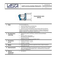
Triangle Retainersfor Ball-Lock Punches, light duty 2664.05.for Ball-Lock Punches, heavy duty 2664.06.2664.05.Execution:Version for metal thicknesses 3 mm.The punch locating hole d 2 is manufacturedto a tolerance of ±0.01 mm relativeto the 6 stud holes G6. This ensures theinterchangeability of the locating platewith other polygon versions.Note:Special punch retainers available to order.2664.05.d 2 10 13 16 20 25 32 38d 4 6 6 6 6 6 6 6M/D 8/9 8/9 8/9 10/11 12/13,5 12/13,5 12/13,5a 43,5 49,5 52,5 59 68,5 68,5 76a 1 19,05 19,05 19,05 19,05 23,82 23,82 27a 2 34 37 38,5 42 46,5 46,5 50a 3 11,12 14,27 15,87 17,47 19,84 19,84 24a 4 10 12 13 14 16 16 18b 41 48,5 51,5 56,5 64,5 64,5 72,5e 1 7,5 6,5 6 5 7 7 10e 2 26,92 29,97 31,75 33,53 40,64 40,64 43,99e 3 9 12 13,5 16,5 22 22 26[K 8 8 8 8 8 8 8t 9 9 9 11 13 13 13R 1 9,5 12,5 14 17 22 22 262664.06.d 2 10 13 16 20 25 32 40d 4 6 6 6 6 6 6 6M/D 8/9 8/9 8/9 10/11 12/13,5 12/13,5 12/13,5a 43,5 49,5 52,5 59 68,5 68,5 76a 1 19,05 19,05 19,05 19,05 23,82 23,82 27a 2 34 37 38,5 42 46,5 46,5 50a 3 11,12 14,27 15,87 17,47 19,84 19,84 24a 4 10 12 13 14 16 16 18b 41 48,5 51,5 56,5 64,5 64,5 72,5e 1 7,5 6,5 6 5 7 7 10e 2 26,92 29,97 31,75 33,53 40,64 40,64 43,99e 3 9 12 13,5 16,5 22 22 26[K 10 12 12 12 12 12 12t 9 9 9 11 13 13 13R 1 9,5 12,5 14 17 22 22 26Ordering example:Triangle retainers = 2664.for ball-lock punches, light duty = 2664.05.d 2 = Ø 13 mm = 2664.05.13Order number = 2664.05.13Ordering example:Triangle retainers = 2664.for ball-lock punches, heavy duty = 2664.06.d 2 = Ø 13 mm = 2664.06.13Order number = 2664.06.132·17390·2002·1 °e 86subject to alterations
Triangle Retainers2664.07. for Ball-Lock Punches, light duty2664.10. for Ball-Lock Punches, heavy dutyExecution:Version for metal thicknesses 3 mm.The punch locating hole d 2 is manufacturedto a tolerance of ±0.01 mm relativeto the 6 stud holes G6. This ensures theinterchangeability of the locating platewith other polygon versions.2664.10.Note:Special punch retainers available to order.2664.07.d 2 6d 4 3M/D 6/6,6a 35a 1 19,05a 2 27a 3 11,12a 4 6b 37,5e 1 9,0e 2 23e 3 8[K 6t 7R 1 82664.10.d 2 10 13 16 20 25 32 40d 4 6 6 6 6 6 6 6M/D 8/9 8/9 8/9 10/11 12/13,5 12/13,5 12/13,5a 43,5 49,5 52,5 59 68,5 68,5 76a 1 19,05 19,05 19,05 19,05 23,82 23,82 27a 2 34 37 38,5 42 46,5 46,5 50a 3 11,12 14,27 15,87 17,47 19,84 19,84 24a 4 10 12 13 14 16 16 18b 41 48,5 51,5 56,5 64,5 64,5 72,5e 1 7,5 6,5 6 5 7 7 10e 2 26,92 29,97 31,75 33,53 40,64 40,64 43,99e 3 9 12 13,5 16,5 22 22 26[K 10 12 12 12 12 12 12t 9 9 9 11 13 13 13R 1 9,5 12,5 14 17 22 22 262·19173·2004·1 °Ordering example:Triangle retainer = 2664.light duty = 2664.07.d 2 = Ø 6 mm = 2664.07.06Order number = 2664.07.06Ordering example:Triangle retainer = 2664.heavy duty = 2664.10.d 2 = Ø 13 mm = 2664.10.13Order number = 2664.10.13subject to alterations e 87
Triangel Retainersfor round Ball-Lock Punches, light duty 2664.08.for round Ball-Lock Punches, heavy duty 2664.09.2664.08.2664.09.2664.08.d 2 10 13 16 20 25 32d 4 6 6 6 6 6 6M/D 8 8 8 10 12 12a 38,5 41,7 43,3 47,5 59,2 59,2a 1 19,05 19,05 19,05 19,05 23,82 23,82a 2 29 29 29 30 37 37a 3 11,12 14,27 15,87 17,47 19,84 19,84b 40,61 47,93 51,59 57,93 70,85 70,85[K 8 8 8 8 8 8t 9 9 9 11 13 13R 1 9,5 12,7 14,3 17,5 22,2 22,2R 2 9,5 9,5 9,5 11 15 152664.09.d 2 10 13 16 20 25 32d 4 6 6 6 6 6 6M/D 8 8 8 10 12 12a 38,5 41,7 43,3 47,5 59,2 59,2a 1 19,05 19,05 19,05 19,05 23,82 23,82a 2 29 29 29 30 37 37a 3 11,12 14,27 15,87 17,47 19,84 19,84b 40,61 47,93 51,59 57,93 70,85 70,85[K 10 12 12 12 12 12t 9 9 9 11 13 13R 1 9,5 12,7 14,3 17,5 22,2 22,2R 2 9,5 9,5 9,5 11 15 15Ordering example:Triangle retainerfor round ball-lock punches = 2664.light duty = 2664.08.d 2 = Ø 20 mm = 2664.08.20Order number = 2664.08.20Ordering example:Triangle retainerfor round ball-lock punches = 2664.heavy duty = 2664.09.d 2 = Ø 20 mm = 2664.09.20Order number = 2664.09.202·17392·2002·1 °e 88subject to alterations
Accessories for Retainers,triangular, for Ball-Lock Punches2·17393·2002·1 °2192.10.Mkll1sd236.1.2666.04.d 22192.72.M42666.06.2666.01.d h62206d 4H72666.03.M8d 2 h62192.72.86Cheese head Pressure diskRetainer [ d2 screw Dowel pin Ball Ball release pin Spring for centring pin Pin screw Stiftschraube2664.05. 10 2192.10.08.035 236.1.0600.020 2666.04.008 2192.72.04.020 2666.06.008 2666.01.10 2666.03.10 2192.72.08.00813 2192.10.08.035 236.1.0600.020 2666.04.008 2192.72.04.020 2666.06.008 2666.01.13 2666.03.13 2192.72.08.00816 2192.10.08.035 236.1.0600.020 2666.04.008 2192.72.04.020 2666.06.008 2666.01.16 2666.03.16 2192.72.08.00820 2192.10.10.035 236.1.0600.020 2666.04.008 2192.72.04.020 2666.06.008 2666.01.20 2666.03.20 2192.72.08.00825 2192.10.12.035 236.1.0600.020 2666.04.008 2192.72.04.020 2666.06.008 2666.01.25 2666.03.25 2192.72.08.00832 2192.10.12.035 236.1.0600.020 2666.04.008 2192.72.04.020 2666.06.008 2666.01.32 2666.03.32 2192.72.08.00838 2192.10.12.035 236.1.0600.020 2666.04.008 2192.72.04.020 2666.06.008 2666.01.38 2666.03.38 2192.72.08.0082664.06./10. 10 2192.10.08.040 236.1.0600.020 2666.04.010 2192.72.04.020 2666.06.010 2666.01.10 2666.03.10 2192.72.08.00813 2192.10.08.040 236.1.0600.020 2666.04.012 2192.72.04.020 2666.06.012 2666.01.13 2666.03.13 2192.72.08.00816 2192.10.08.040 236.1.0600.020 2666.04.012 2192.72.04.020 2666.06.012 2666.01.16 2666.03.16 2192.72.08.00820 2192.10.10.050 236.1.0600.020 2666.04.012 2192.72.04.020 2666.06.012 2666.01.20 2666.03.20 2192.72.08.00825 2192.10.12.050 236.1.0600.020 2666.04.012 2192.72.04.020 2666.06.012 2666.01.25 2666.03.25 2192.72.08.00832 2192.10.12.050 236.1.0600.020 2666.04.012 2192.72.04.020 2666.06.012 2666.01.32 2666.03.32 2192.72.08.00840 2192.10.12.050 236.1.0600.020 2666.04.012 2192.72.04.020 2666.06.012 2666.01.40 2666.03.38 2192.72.08.0082664.07. 6 2192.10.06.035 236.1.0600.020 2666.04.006 2192.72.04.020 2666.06.006 2666.01.06 2666.03.06 2192.72.08.0082664.08. 10 2192.10.08.035 236.1.0600.020 2666.04.008 2192.72.04.020 2666.06.008 2666.01.10 2666.03.10 2192.72.08.00813 2192.10.08.035 236.1.0600.020 2666.04.008 2192.72.04.020 2666.06.008 2666.01.13 2666.03.13 2192.72.08.00816 2192.10.08.035 236.1.0600.020 2666.04.008 2192.72.04.020 2666.06.008 2666.01.16 2666.03.16 2192.72.08.00820 2192.10.10.035 236.1.0600.020 2666.04.008 2192.72.04.020 2666.06.008 2666.01.20 2666.03.20 2192.72.08.00825 2192.10.12.035 236.1.0600.020 2666.04.008 2192.72.04.020 2666.06.008 2666.01.25 2666.03.25 2192.72.08.00832 2192.10.12.035 236.1.0600.020 2666.04.008 2192.72.04.020 2666.06.008 2666.01.32 2666.03.32 2192.72.08.0082664.09. 10 2192.10.08.040 236.1.0600.020 2666.04.010 2192.72.04.020 2666.06.010 2666.01.10 2666.03.10 2192.72.08.00813 2192.10.08.040 236.1.0600.020 2666.04.012 2192.72.04.020 2666.06.012 2666.01.13 2666.03.13 2192.72.08.00816 2192.10.08.040 236.1.0600.020 2666.04.012 2192.72.04.020 2666.06.012 2666.01.16 2666.03.16 2192.72.08.00820 2192.10.10.040 236.1.0600.020 2666.04.012 2192.72.04.020 2666.06.012 2666.01.20 2666.03.20 2192.72.08.00825 2192.10.12.040 236.1.0600.020 2666.04.012 2192.72.04.020 2666.06.012 2666.01.25 2666.03.25 2192.72.08.00832 2192.10.12.040 236.1.0600.020 2666.04.012 2192.72.04.020 2666.06.012 2666.01.32 2666.03.32 2192.72.08.008Ball release tool Hook shape straight straight withthreaded tip2666.05.012666.05.022666.05.03subject to alterations e 89
Square Retainers 2661.07.for Ball-Lock Punches, light duty 2661.08.2661.07.Execution:The centres of the pinholes d 5 are thereference points for the position of thepunch bore.The dimensions e and e1 have a toleranceof ±0,005 mm.The square ball-lock retainers areinterchangeable.The order must specify position 1 or 2 forthe locking ball.Ball channel horizontal = 1Ball channel vertical = 2Note:Supplied with dowel pins and screwsDIN EN ISO 4762.2661.08.Execution:The centres of the pinholes d 5 are thereference points for the position of thepunch bore.The e-dimensions have a tolerance of± 0,005 mm.The square ball-lock retainers areinterchangeable.Note:Supplied with dowel pins and screwsDIN EN ISO 4762.2661.07.d 2 d 5 M/D a a 2 b 2 e e 1 t10 8 8/9 45 11 15 28 1 9131620 10 10/11 56 17 18 32 5 11252661.08.d 2 d 5 M/D a a 1 , e t6 8 8/9 45 13 910131620 10 10/11 56 16 1125 12/13,5 63 20 13Ordering code (example):Square Retainer = 2661.for Ball-Lock Punch = 2661.07.d 2 = Ø 20 mm = 2661.07.20.Vertical ball race = 2661.07.20.2Order No = 2661.07.20.2Ordering code (example):Square Retainer = 2661.for Ball-Lock Punch = 2661.07.d 2 = Ø 20 mm = 2661.07.20.Vertical ball race = 2661.07.20.2Order No = 2661.07.20.22·10396·7·2 °e 90subject to alterations
Rectangular Retainers,2662.05. for Ball-Lock PunchesMaterial:Punch plate case-hardened 740± 40 HV 10Pressure plate hardened 60 +2 HRCExecution:The centres of the pin holes d 5 are thereference points for the position of thepunch bore.The dimensions e, e 1 and e 1 have atolerance of ± 0,005 mm.The rectangular ball-lock retainers areinterchangeable.Note:Supplied with dowel pins and screwsDIN EN ISO 4762.2662.05.2662.05.d 2 d 5 M/D a a 3 a 1 b e e 1 e 2 c t6 8 8/9 75 60 7 32 50 25 9 16 910131620 10 10/11 85 63 9 40 53 28 11 20 11252·10399·7·2 °Ordering code (example):Rectangular Retainer = 2662.for Ball-Lock Punch to VDI 3374 = 2662.05.d 2 = Ø 20 mm = 2662.05.20Order No = 2662.05.20subject to alterations e 91
2· 19141·2003·1 °e 92subject to alterations
Precision RetainersISO2·17403·2002·1 °subject to alterations e 93
Triangle Retainers,for round Punches, ISO 8020 2664.02.for Punches, ISO 8020 2664.04.2664.02.Execution:The centres of the pinholes d 5 are thereference points for the position of thepunch bore.The dimensions e 1 , e 2 and e 3 have atolerance of ± 0.01 mm.The triangle ball-lock retainers areinterchangeable.Note:Pressure plate 2665.01 to be orderedseparately for the receiving punch plate.2664.04.Execution:The centres of the pinholes d 5 are thereference points for the position of thepunch bore.The dimensions e 1, e 2 and e 3 have atolerance of ± 0.01 mm.The triangle ball-lock retainers areinterchangeable.Note:Pressure plate 2665.01 to be orderedseparately for the receiving punch plate.2664.02.d 2 10 13 16 20 25 32d 3 14 17 20 24 29 36M/D 8/9 8/9 8/9 10/11 12/13,5 12/13,5a 43,5 49,5 52,5 59 68,5 68,5a 1 19,05 19,05 19,05 19,05 23,82 23,82a 2 34 37 38,5 42 46,5 46,5a 3 11,12 14,27 15,87 17,47 19,84 19,84a 4 10 12 13 14 16 16b 41,0 48,5 51,5 56,5 64,5 64,5e 1 7,5 6,5 6 5 7 7e 2 26,92 29,97 31,75 33,53 40,64 40,64e 3 9 12 13,5 16,5 22 22t 9 9 9 11 13 13R 1 9,5 12,5 14 17 22 222664.04.d 2 10 13 16 20 25 32M/D 8/9 8/9 8/9 10/11 12/13,5 12/13,5a 43,5 49,5 52,5 59 68,5 68,5a 1 19,05 19,05 19,05 19,05 23,82 23,82a 2 34 37 38,5 42 46,5 46,5a 3 11,12 14,27 15,87 17,47 19,84 19,84a 4 10 12 13 14 16 16b 41,0 48,5 51,5 56,5 64,5 64,5b 3 12 15 18 23 28 35b 4 5 6,5 8 10 12,5 16e 1 7,5 6,5 6 5 7 7e 2 26,92 29,97 31,75 33,53 40,64 40,64e 3 9 12 13,5 16,5 22 22t 9 9 9 11 13 13R 1 9,5 12,5 14 17 22 22Ordering example:Triangle retainers = 2664.for round Punches, ISO 8020 = 2664.02.d 2 = [ 13 mm = 2664.02.13Order number = 2664.02.13Ordering example:Triangle retainers = 2664.for Punches, ISO 8020 = 2664.04.d 2 = [13 mm = 2664.04.13Order number = 2664.04.132·17304·2002·1 °e 94subject to alterations
Accessories for Retainers,triangular, for Ball-Lock Punch, ISO 80202192.10. 236.1.2192.72. 2665.01.Cheese headRetainer Ø d 2 screw Dowel pin Pin screw Pressure disk2664.02./04. 10 2192.10.08.035 236.1.0600.020 2192.72.08.008 2665.01.1013 2192.10.08.035 236.1.0600.020 2192.72.08.008 2665.01.1316 2192.10.08.035 236.1.0600.020 2192.72.08.008 2665.01.1620 2192.10.10.035 236.1.0600.020 2192.72.08.008 2665.01.2025 2192.10.12.035 236.1.0600.020 2192.72.08.008 2665.01.2532 2192.10.12.035 236.1.0600.020 2192.72.08.008 2665.01.322·17406·2002·1 °subject to alterations e 95
Square Retainers 2661.01.for Punches to ISO 8020 2661.02.2661.01. Execution:The centres of the pinholes d 5 are thereference points for the position of thepunch bore.The dimensions e and e 1 have a toleranceof ± 0,005 mm.The square retainers are interchangeable.Note:Supplied with dowel pins and screwsDIN EN ISO 4762.2661.02. Execution:The centres of the pinholes d 5 are thereference points for the position of thepunch bore.The dimensions e and e 1 have a toleranceof ± 0,005 mm.The square retainers are interchangeable.Note:Supplied with dowel pins and screws DINEN ISO 4762.2661.01.d 2 d 3 d 5 M/D a a 1 , e e 1 t6 10 8 8/9 45 13 15,5 98 1210 1413 1716 2020 25 10 10/11 56 16 19 1125 30 12/13,5 63 20 22,5 132661.02.d 2 d 3 d 5 M/D a a 1 , e e 1 b 3 t6 10 8 8/9 45 13 15,5 8 98 12 1010 14 1213 17 1516 20 1820 25 10 10/11 56 16 19 22,5 1125 30 12/13,5 63 20 22,5 27,5 13Ordering code (example):Square Retainer = 2661.for punch to ISO 8020 = 2661.01.d 2 = [ 13 mm = 2661.01.13Order No = 2661.01.13Ordering code (example):Square Retainer = 2661.for punch to ISO 8020 = 2661.02.d 2 = [ 20 mm = 2661.02.20Order No = 2661.02.202·10393·7·2 °e 96subject to alterations
2662.01. Rectangular Retainers2662.02. for Punches to ISO 8020Execution:The centres of the pinholes d 5 are thereference points for the position of thepunch bore.The dimensions b, e 1 and e 2 have atolerance of ± 0,005 mm.The rectangular retainers areinterchangeable.Note:Supplied with dowel pins and screwsDIN EN ISO 4762.2662.01.Execution:The centres of the pinholes d 5 are thereference points for the position of thepunch bore.The dimensions e, e 1 and e 2 have atolerance of ± 0,005 mm.The rectangular retainers areinterchangeable.Note:Supplied with dowel pins and screwsDIN EN ISO 4762.2662.02.2662.01.d 2 d 3 d 5 M/D a a 1 a 3 b e e 1 e 2 c t6 10 8 8/9 60 7 50 32 40 15 9 11 98 1210 1413 17 67 53 43 18 1616 2020 25 10 10/11 80 9 60 40 50 25 11 22 1125 302662.02.d 2 d 3 d 5 M/D a a 1 a 3 b b 3 b 4 e e 1 e 2 c t6 10 8 8/9 60 7 50 32 8 3 40 15 9 11 98 12 10 410 14 12 513 17 67 53 15 6,5 43 18 1616 20 18 820 25 10 10/11 80 9 60 40 22,5 10 50 25 11 22 1125 30 27,5 12,52·10397·7·2 °Ordering code (example):Rectangular Retainer = 2662.for Punch to ISO 8020 = 2662.01.d 2 = [ 13 mm = 2662.01.13Order No = 2662.01.13Ordering code (example):Rectangular Retainer = 2662.for Punch to ISO 8020 = 2662.02.d 2 = [ 20 mm = 2662.02.20Order No = 2662.02.20subject to alterations e 97
2· 19156·2003·1 °e 98subject to alterations
Precision RetainersVDI2· 17418·2002·1 °subject to alterations e 99
Square Retainers 2661.03.for round Punches 2661.04.2661.03.Execution:The centres of the pinholes d 5 are thereference points for the position of thepunch bore.The e-dimensions have a tolerance of± 0,005 mm.The square retainers are interchangeable.Note:Supplied with dowel pins and screwsDIN EN ISO 4762.2661.04.Execution:The centres of the pinholes d 5 are thereference points for the position of thepunch bore.The e-dimensions have a tolerance of± 0,005 mm.The square retainers are interchangeable.Note:Supplied with dowel pins and screwsDIN EN ISO 4762.2661.03.d 2 d 3 d 5 M/D a a 2 b 2 e e 1 t10 14 8 8/9 45 11 15 28 1 913 1716 2020 25 10 10/11 56 17 18 32 5 1125 302661.04.d 2 d 3 d 5 M/D a a 1 , e t10 14 8 8/9 45 13 913 1716 2020 25 10 10/11 56 16 1125 30 12/13,5 63 20 1332 37Ordering code (example):Square retainer = 2661.for punches = 2661.03.d 2 = [ 10 mm = 2661.03.10Order No = 2661.03.10Ordering code (example):Square retainer = 2661.for punches = 2661.04.d 2 = [ 16 mm = 2661.04.16Order No = 2661.04.162·10394·7·2 °e 100subject to alterations
2661.05 Square Retainers2661.06. for Profile PunchesExecution:The centres of the pin holes d 5 are thereference points for the position of thepunch bore.The e-dimensions have a tolerance of± 0,005 mm.The rectangular retainers areinterchangeable.Note:Supplied with dowel pins and screwsDIN EN ISO 4762.2661.05.Execution:The centres of the pin holes d 5 are thereference points for the position of thepunch bore.The e-dimensions have a tolerance of± 0,005 mm.The rectangular retainers areinterchangeable.Note:Supplied with dowel pins and screwsDIN EN ISO 4762.2661.06.2661.05.d 2 d 3 d 5 M/D a a 2 a 1 e e 1 b 4 t10 14 8 8/9 45 11 15 28 1 5 913 17 6,516 20 820 25 10 10/11 56 17 18 32 5 10 1125 30 12,52661.06.d 2 d 3 d 5 M/D a a 1 , e b 3 b 4 t10 14 8 8/9 45 13 12 5 913 17 15 6,516 20 18 820 25 10 10/11 56 16 22,5 10 1125 30 12/13,5 63 20 27,5 12,52·10395·7·2 °Ordering code (example):Square retainer = 2661.for punches = 2662.05.d 2 = [ 13 mm = 2662.05.13Order No = 2662.05.13Ordering code (example):Square retainer = 2661.for punches = 2661.06.d 2 = [ 20 mm = 2661.06.20Order No = 2661.06.20subject to alterations e 101
Rectangular Retainers 2662.03.for Punches to VDI 3374 2662.04.2662.03.Execution:The centres of the pin holes d 5 are thereference points for the position of thepunch bore.The e-dimensions have a tolerance of± 0,005 mm.The rectangular retainers areinterchangeable.Note:Supplied with dowel pins and screwsDIN EN ISO 4762.2662.04.Execution:The centres of the pin holes d 5 are thereference points for the position of thepunch bore.The e-dimensions have a tolerance of± 0,005 mm.The rectangular retainers areinterchangeable.Note:Supplied with dowel pins and screwsDIN EN ISO 4762.2662.03.d 2 d 3 d 5 M/D a a 1 a 3 b e e 1 e 2 c t t 16 10 8 8/9 75 7 60 32 50 25 9 16 9 310 14 413 1716 2020 25 10 10/11 85 9 63 40 53 28 11 20 1125 3032 37 12/13,5 95 13 70 50 15 30 132662.04.d 2 d 3 d 5 M/D a a 1 a 3 b b 3 b 4 e e 1 e 2 c t t 16 10 8 8/9 75 7 60 32 8 3 50 25 9 16 9 310 14 12 5 413 17 15 6,516 20 18 820 25 10 10/11 85 9 63 40 22,5 10 53 28 11 20 1125 30 27,5 12,5Ordering code (example):Rectangular Retainer = 2662.for round punches to VDI 3374 = 2662.03.d 2 = [ 10 mm = 2662.03.10Order No = 2662.03.10Ordering code (example):Rectangular Retainer = 2662.for profile punches to VDI 3374 = 2662.04.d 2 = [ 16 mm = 2662.04.16Order No = 2662.04.162·10398·7·2 °e 102subject to alterations
Accessories2·17427·2002·1 °subject to alterations e 103
Stripping unit 2431.7.2431.7.Material:FIBROFLEX ® 95 Shore AInstallation example:Note:Stripping units can be used for retainers2664.02./.04./.05./.06.Stripping unit lenght ld 2 35 43 53 63 7310 V V V V13 V V V V V16 V V V V V20 V V V V V25 V V V V V32 V V V V V38 V V V V40 V V V VPunch lengths in useBall-lock punch, light duty 63 71 80 090 100Ball-lock punch, heavy duty 71 80 90 100 110Precision punch ISO 8020 – 71 80 090 1002431.7. ld 2 d 1 d 3 d 4 d 5 max. b 35 43 53 63 7310 18 21 3 22 6 V V V V13 23 26 3 26,5 6 V V V V V16 30 33 3 34 6 V V V V V20 33 36 3 38 7 V V V V V25 40 43 3 47,6 7 V V V V V32 50 54 4 57,9 7 V V V V V38 60 64 4 69,6 8 V V V V40 60 64 4 69,6 8 V V V VOrdering example:Stripping unit = 2431.7.d 2 = 10 mm = 2431.7.10.l = 53 mm = 2431.7.10.53Order number = 2431.7.10.53* values for the stripping force are dependent on a number ofparameters (e.g. lubricant, temperature etc.) and may vary fromthose given here.** max spring travel should not exceed 15% of the lengthStripping forces (N)*Spring travel 3mm 6mm 9mm 3mm 6mm 9mm 3mm 6mm 9mm 3mm 6mm 9mm 3mm 6mm 9mmd 2 Length 35 35 35 43 43 43 53 53 53 63 63 63 73 73 7310 1300 ** ** 01000 01700 ** 0900 01400 ** 0700 01200 01600 — — —13 2100 ** ** 01700 02700 ** 1400 02200 ** 1200 01900 02400 1000 1600 0 200016 3000 ** ** 02500 04000 ** 2000 03200 ** 1700 02700 03500 1500 2400 0 300020 3500 ** ** 02900 04700 ** 2400 03800 ** 2000 03200 04100 1700 2700 0 360025 5400 ** ** 04400 07100 ** 3600 05800 ** 3000 04900 06300 2600 4200 0 550032 8400 ** ** 06800 10900 ** 5500 08800 ** 4700 07500 09700 4000 6400 0 840038 — — — — — ** 7000 10400 ** 6100 9200 12300 5000 7600 1010040 — — — 10400 16600 ** 8500 13600 ** 7000 11300 14800 6000 9800 1270002· 17428·2002·1 °e 104subject to alterations
2667. Stripping unit mountings2667.1. 2667.2.Installation example:Note:Thrust plate, maounting plate and screwmust all be ordered individually.Mounting on retainer for ball-lock punch,multi-sidedMounting on precision retainer,multi-sided ISO 80202667.1/2.d 2 d 1 d 3 R 1 a10 18 21 13 2813 23 26 15,5 3116 30 33 18 32,920 33 36 20,5 34,825 40 43 24 39,832 50 54 31 41,338 60 64 36 4440 60 64 36 442· 17429·2002·1 °Ordering example:Stripping unit mountings = 2667.Type = 2667.1.d 2 = 10mm = 2667.1.010Order number = 2667.1.010subject to alterations e 105
Special PunchesCustom madee 106subject to alterations
FIBRO manufactures Special Form Punches and -Matriceson most modern equipment. Projection FormGrinding, Creep Feed Grinding, EDM and Wire-EDM areused acc. to design details. Many years of experienceenable FIBRO to chose best suitable materials andmethods. We manufacture to customer´s drawings -:Piercing Punches ● Draw Punched ● Form Punches ●Pre-Extrusion Punches and Ejectors for Bolt Mnfr. ●Flow-Forming Punches ● Punches with 30° -ConicalHeads, or other head shapesHigh-Precision Special Partsto Customer´s Drawings2·2378·2000·2 °subject to alterations e 107
Precision Punches, Square/Rectangular 230.without/with Hot Upset-Forged Head 231.230. Shape A 231. Shape BMaterial:HSSOrder No: Shape A = 230.3., Shape B = 231.3.Hardness: Shank 64±2 HRCHead 52±3 HRCExecution:Punch shanks precision ground.Heads hot upset forged – ground on special request.Description of FIBRO materials for die components:pages E 10 and E 11.230.a b l 11– 8 12–10 23–12 34–12 45–15 56–20 67–24 78–24 89–28 910–34 1012–34 12stock length of squarepunches: 73,5 mm;other materials anddimensions on request.231.a b h l 11– 8 1 1,22–10 2 1,43–12 3 1,84–12 45–15 56–20 6 2,07–24 7 2,88–24 89–28 910–34 1012–34 12stock length of squarepunches: 71 mmother materials anddimensions on request.Ordering Code (example):Punch = 231.2.1000.0600.071Material HSS = 231.3.1000.0600.071a = 10 mm = 231.2.1000.0600.071b = 6 mm = 231.2.1000.0600.071l 1 = 71 mm = 231.2.1000.0600.071Order No = 231.3.1000.0600.0712·2372·7·2 °e 108subject to alterations
Precision Dowel Pins (Parallel) with Internal Extracting Thread236.1. similar to DIN EN ISO 8735/ISO 8735236.001 Dowel Pin Extractor “FIBROZIPP”236.1.Material: Case-hardening steel – core strength (tensile)800 –1000 N/mm 2 .Order No: 236.1.Hardness: 60±2 HRCNitrided on request.Execution:Case-hardened and ground to finest finish. FIBRO Dowel Pins aremanufactured with the exacting requirements of high class diemakingin mind. Whereas DIN EN ISO 8735 stipulates ISO Class 6 fordowels, we produce our pins to m5.FIBRO Dowels with internal extracting thread deviate from DIN inthat they are case-hardened and that a smaller thread is used.This increases the crossection around the threaded hole and thusprevents breaking.236.001FIBROZIPPExtraction tool for the fast and convenient removal of dowels withinternal extracting thread – also for shafts, plugs and other machinecomponents.The tool comes with interchangeable adaptors and screws, to fitall threads from M3 to M16.Ordering Code (example):Dowel Pin with Extracting Thread = 236.1.d 1 = [ 12 mm = 236.1.1200.l 1 = 100 mm = 236.1.1200.100Order No = 236.1.1200.1002 · 2381 · 2007 · 5 l236.1.d 1 6 8 10 12 14 16 20 25d 2 M 4 M 5 M 6 M 6 M 8 M 8 M 10 M 16t 1 6 8 10 10 12 12 16 24l 2 2,1 2,6 3 3,8 4 4,7 6 6r 6 8 10 12 14 16 20 25l 116 ●18 ●20 ● ●24 ● ● ●28 ● ● ● ●32 ● ● ● ● ● ●36 ● ● ● ● ● ● ●40 ● ● ● ● ● ● ●45 ● ● ● ● ● ● ● ●50 ● ● ● ● ● ● ● ●55 ● ● ● ● ● ● ● ●60 ● ● ● ● ● ● ● ●70 ● ● ● ● ● ● ●80 ● ● ● ● ● ● ●90 ● ● ● ● ● ● ●100 ● ● ● ● ● ● ●120 ● ● ● ● ●subject to alterations e 109
Precision Dowel Pins (Parallel) with Internal Extracting Threadsimilar to DIN EN ISO 8735/ISO 8735 2361.1.Dowel Pin Extractor "FIBROZIPP" 236.0012361.1.236.001 FIBROZIPPExtraction tool for the fast and convenient removal of dowels withinternal extracting thread – also for shafts, plugs and other machinecomponents.The tool comes with interchangeable adaptors and screws, to fitall threads from M3 to M16.Material:WS Tough and hard tool steel, wear resistant –core strength (tensile) 600 N/mm 2 min.Order No: 2361.1.Hardness: 60±2 HRCExecution:Hardened and ground to finest finish. FIBRO Dowel Pins aremanufactured with the exacting requirements of high classdiemaking in mind.Ordering Code (example):Dowel Pin = 2361.1.d 1 = [ 10 mm = 2361.1.1000.l 1 = 45 mm = 2361.1.1000.045Order No = 2361.1.1000.045e 1102361.1.d 1 4 5 6 8 10 12 14 16 20d 2 M 3 M 3 M 4 M 5 M 6 M 6 M 8 M 8 M 10t 1 4,5 6 6 8 10 10 12 12 16l 2 1,3 1,7 2,1 2,6 3 3,8 4 4,7 6r 4 5 6 8 10 12 14 16 20l 108 ●10 ● ●12 ● ● ●14 ● ● ●16 ● ● ● ● ●18 ● ● ● ● ●20 ● ● ● ● ● ●22 ● ●24 ● ● ● ● ● ●26 ● ●28 ● ● ● ● ● ● ●30 ● ● ● ● ● ●32 ● ● ● ● ● ● ● ●36 ● ● ● ● ● ● ● ● ●40 ● ● ● ● ● ● ● ● ●45 ● ● ● ● ● ● ● ●50 ● ● ● ● ● ● ● ● ●55 ● ● ● ● ● ● ● ●60 ● ● ● ● ● ● ● ●70 ● ● ● ● ● ● ●80 ● ● ● ● ● ● ●90 ● ● ● ● ● ●100 ● ● ● ● ● ●120 ● ● ● ● ● ●subject to alterations2 · 2381 · 2007·1 l
265.1. High-Precision Liner Bushes for Dowel Pins, for bonding2650.1. High-Precision Liner Bushes for Dowel Pins, for push fit265.1.for epoxy bonding2650.1.for push fitMaterial:Tool Steel, hardenedHardness 54±2 HRCMaterial:Tool Steel, hardenedHardness 54±2 HRCEpoxy-BondingFIBRO Hardened Dowel Liner Bushes solve the problem of wearon soft parts subjected to frequent dismantling. Held in perfectco-axial alignment by the close-fitting dowel, they are epoxy-bondedinto rough-drilled clearance holes. In hardened parts, Dowel LinerBushes help to overcome the ever-present toolroom problem of heattreatment distortion – insurmountable exeptwhere jig grinding facilities are available and justifiable on costgrounds. Retainer holes for Dowel Liner Bushes should beapproximately 2 mm larger in diameter than the bush O.D. –a coarse finish is desirable. Following exact positioning/aligning,FIBROLIT ® ZWO or FIBROFIX ® SECHS is used for bonding.Push FitThe position of the bush is given by push fit hole tolerance H 6.The adhesive order no. 281.648 provides optimum bush retentionwhilst offering the following advantages:– high accuracy and stiffness– no problems to find position when changing bushings.We do not recommend to press fit bushings.2·2376·2000·4 °Ordering Code (example):One Dowel Liner Bush – only –Dowel Liner Bush = 265. analogous 2650.Material: Tool Steel = 265.1.d 1 = [ 8,0 mm = 265.1.0800.Quantity: one = 265.1.0800.1Order No = 265.1.0800.1Ordering Code (example):One Dowel Liner Bush + Matching DowelDowel Liner Bush = 265. analogous 2650.Material: Tool Steel = 265.1.d 1 = [ 8,0 mm = 265.1.0800.Quantity: one = 265.1.0800.1.Dowel: length= 40 mm = 265.1.0800.1.040Order No = 265.1.0800.1.040Ordering Code (example):Two Dowel Liner Bushes + one DowelDowel Liner Bush = 265. analogous 2650.Material: Tool Steel = 265.1.d 1 = [ 8,0 mm = 265.1.0800.Quantity: two = 265.1.0800.2.Dowel: length= 50 mm = 265.1.0800.2.050Order No = 265.1.0800.2.050265.1.d 1 d D D 1 l 1 l 26 7 10 12 25 128 9 12 14 30 1610 11 16 18 36 202650.1.d 1 d D D H6 1 l 1 l 26 7 10 10 25 128 9 12 12 30 1610 11 16 16 36 20subject to alterations e 111
Precision Dowel Pins (Parallel)similar to DIN EN ISO 8734/ISO 8734 235.1.235.1.Execution:Hardened and ground to finest finish.FIBRO-Dowel Pins are manufactured with the exactingrequirements of high class diemaking in mind. WhereasDIN EN ISO 8734 stipulates ISO Class 6 for dowels, weproduce our pins to m5.Material:WS Tough and hard tool steel, wear resistant.over 6 mm: Case-hardening steel –core strength (tensile) 800 –1000 N/mm 2 .Order No: 235.1.Hardness: 60±2 HRCNitrided on request.Ordering Code (example):Dowel Pin = 235.1.d 1 0= [ 10 mm = 235.1.1000.l 1 0 = 80 mm = 235.1.1000.080Order No = 235.1.1000.080235.1.d 1 1 1,5 2 2,5 3 4 5 6 8 10 12 14 16 20l 2 0,48 0,62 0,78 0,95 1,1 1,4 1,7 2,1 2,6 3 3,8 3,8 4,7 6r 1 1,6 2 2,5 3 4 5 6 8 10 12 16 16 20l 16● ● ● ● ●8 ● ● ● ● ● ● ●10 ● ● ● ● ● ● ● ● ●12 ● ● ● ● ● ● ● ● ●14 ● ● ● ● ● ● ● ●16 ● ● ● ● ● ● ● ● ●18 ● ● ● ● ● ● ● ●20 ● ● ● ● ● ● ● ● ●24 ● ● ● ● ● ● ● ● ●28 ● ● ● ● ● ● ● ● ●32 ● ● ● ● ● ● ● ● ●36 ● ● ● ● ● ● ● ● ● ●40 ● ● ● ● ● ● ● ● ●45 ● ● ● ● ● ● ● ● ●50 ● ● ● ● ● ● ● ●55 ● ● ● ● ● ● ● ● ●60 ● ● ● ● ● ● ● ● ●70 ● ● ● ● ● ● ● ●80 ● ● ● ● ● ● ● ●90 ● ● ● ● ● ● ●100 ● ● ● ● ● ● ●120 ● ● ● ● ● ●130 ●140 ● ●2·2380·8·4 °e 112subject to alterations
Precision Dowel Pins (Parallel)2351.1. similar to DIN EN ISO 8734/ISO 87342351.1.Material:WS Tough and hard tool steel,case-hardening steel – core strength (tensile)600 N/mm 2Order No: 2351.1.Hardness: 60±2 HRCExecution:Hardened and ground to finest finish.FIBRO-Dowel Pins are manufactured with the exactingrequirements of high class diemaking in mind.Ordering Code (example):Dowel Pin = 2351.1.[ d 1 = 10 mm = 2351.1.1000.l 1 = 45 mm = 235.11.1000.045Order No = 2351.1.1000.0452351.1.d 1 1 1,5 2 2,5 3 4 5 6 8 10 12 14 16 20l 2 0,4 0,5 0,6 0,7 0,8 1 1,2 1,5 1,8 2 2,5 2,5 3 4r 1 1,6 2 2,5 3 4 5 6 8 10 12 16 16 20l 14● ● ●5 ● ● ● ● ●6 ● ● ● ● ● ●8 ● ● ● ● ● ● ● ●10 ● ● ● ● ● ● ● ●12 ● ● ● ● ● ● ● ●14 ● ● ● ● ● ● ● ●16 ● ● ● ● ● ● ● ● ●18 ● ● ● ● ● ● ● ●20 ● ● ● ● ● ● ● ● ● ●22 ● ● ● ● ● ● ● ● ●24 ● ● ● ● ● ● ● ● ● ● ● ●26 ● ● ● ● ● ● ● ● ● ●28 ● ● ● ● ● ● ● ● ● ● ●30 ● ● ● ● ● ● ● ● ● ● ●32 ● ● ● ● ● ● ● ● ● ● ●36 ● ● ● ● ● ● ● ● ● ●40 ● ● ● ● ● ● ● ● ● ● ●45 ● ● ● ● ● ● ● ● ● ●50 ● ● ● ● ● ● ● ● ● ●55 ● ● ● ● ● ● ● ●60 ● ● ● ● ● ● ● ● ● ●70 ● ● ● ● ● ● ● ● ●80 ● ● ● ● ● ● ● ● ●90 ● ● ● ● ● ● ●100 ● ● ● ● ● ● ●120 ● ● ● ● ● ●2·2380·8·4 °subject to alterations e 113
2·2356·7·1 °e 114subject to alterations
Precision Drill Bushes Shape A276. DIN 172, with collar277. DIN 179, without collarMaterial:Special Steel, hardenedHardness: 740±40 HV10Execution:Diameters d 1 and d 2 and shoulder precisionground.276. DIN 172Shape AOrdering Code (example):Drill Bush = 276.Material: Special Steel = 276.1.d 1 = 8,0 mm = 276.1.0800.l 1 = 20 mm = 276.1.0800.020Order No = 276.1.0800.020Material:Special Steel, hardenedHardness: 740±40 HV10277. DIN 179Shape AExecution:Diameters d 1 and d 2 precision ground.Ordering code (example):Drill Bush = 277.Material: Special Steel = 277.1.d 1 = 9,1 mm = 277.1.0910.l 1 = 25 mm = 277.1.0910.025Order No = 277.1.0910.0252·2375·8·4 °276. short medium longd 1 * d 2 d 3 l 1 l 2 l 1 l 2 l 1 l 20,4 – 1,0 3 6 6 4 9 7 – –1,1 – 1,8 4 7 6 4 9 7 – –1,9 – 2,6 5 8 6 4 9 7 – –2,7 – 3,3 6 9 8 5,5 12 9,5 16 13,53,4 – 4,0 7 10 8 5,5 12 9,5 16 13,54,1 – 5,0 8 11 8 5,5 12 9,5 16 13,55,1 – 6,0 10 13 10 7 16 13 20 176,1 – 8,0 12 15 10 7 16 13 20 178,1 – 10,0 15 18 12 9 20 17 25 2210,1 – 12,0 18 22 12 8 20 16 25 2112,1 – 15,0 22 26 16 12 28 24 36 3215,1 – 18,0 26 30 16 12 28 24 36 3218,1 – 22,0 30 34 20 15 36 31 45 4022,1 – 26,0 35 39 20 15 36 31 45 4026,1 – 30,0 42 46 25 20 45 40 56 5130,1 – 35,0 48 52 25 20 45 40 56 5135,1 – 42,0 55 59 30 25 56 51 67 6242,1 – 48,0 62 66 30 24 56 50 67 6148,1 – 55,0 70 74 30 24 56 50 67 6155,1 – 63,0 78 82 35 29 67 61 78 72*diameter steps 0,1 mm277. short medium longd 1 * d 2 l 1 l 1 l 10,4 – 1,0 3 6 9 –1,1 – 1,8 4 6 9 –1,9 – 2,6 5 6 9 –2,7 – 3,3 6 8 12 163,4 – 4,0 7 8 12 164,1 – 5,0 8 8 12 165,1 – 6,0 10 10 16 206,1 – 8,0 12 10 16 208,1 – 10,0 15 12 20 2510,1 – 12,0 18 12 20 2512,1 – 15,0 22 16 28 3615,1 – 18,0 26 16 28 3618,1 – 22,0 30 20 36 4522,1 – 26,0 35 20 36 4526,1 – 30,0 42 25 45 5630,1 – 35,0 48 25 45 5635,1 – 42,0 55 30 56 6742,1 – 48,0 62 30 56 6748,1 – 55,0 70 30 56 6755,1 – 63,0 78 35 67 78*diameter steps 0,1 mmsubject to alterations e 115
Hardened Ejector Pins –similar to DIN 1530 Shape A-ISO 6751 237.1.237.1. Material:rd 2 -0,2k -0,05l1 +2WSOrder No 237.1.Hardness: Shank 62±2 HRCHead 45±5 HRCExecution:Similar to DIN 1530 Shape A.Shank hardened and precision ground.Head hot upset-forged.d 1 g6Description of FIBRO materials for tooland die components: pages E 10 –E 11.Ordering Code (example):Ejector Pin = 237.Material WS = 237.1.d 1 = Ø 4,0 mm = 237.1.0400.l 1 = 200 mm = 237.1.0400.200Order No = 237.1.0400.200237.1.l 1d 1 d 2 k r 40 63 80 100 125 160 200 250 315 400 500 630 800 1000 1250 16001 2,5 1,2 0,2 ● ● ● ● ● ● ●1,1 2,5 1,2 ● ● ● ● ● ● ●1,2 2,5 1,2 ● ● ● ● ● ● ●1,3 3 1,5 ● ● ● ● ● ● ●1,4 3 1,5 ● ● ● ● ● ● ●1,5 3 1,5 ● ● ● ● ● ● ●1,6 ● ● ● ● ● ● ●1,7 3 1,5 ● ● ● ● ● ● ●1,8 3 1,5 ● ● ● ● ● ● ●1,9 3 1,5 ● ● ● ● ● ●2 4 2 ● ● ● ● ● ● ● ● ●2,2 ● ● ● ● ● ●2,5 5 0,3 ● ● ● ● ● ● ● ● ●2,7 ● ● ● ● ● ●3 6 3 ● ● ● ● ● ● ● ● ● ● ●3,2 ● ● ● ● ● ● ●3,5 7 ● ● ● ● ● ● ●3,7 ● ● ● ● ● ● ●4 8 ● ● ● ● ● ● ● ● ● ● ●4,2 ● ● ● ● ● ● ●4,5 ● ● ● ● ● ● ●4,7 ● ● ● ● ● ● ●5 10 ● ● ● ● ● ● ● ● ● ● ● ● ●5,2 ● ● ● ● ● ● ● ●5,5 ● ● ● ● ● ● ● ●6 12 5 0,5 ● ● ● ● ● ● ● ● ● ● ● ● ●6,2 ● ● ● ● ● ● ● ● ●6,5 ● ● ● ● ● ● ● ●7 ● ● ● ● ● ● ● ● ●8 14 ● ● ● ● ● ● ● ● ● ● ● ● ● ● V8,2 ● ● ● ● ● ● ● ● ● ●8,5 ● ● ● ● ● ● ● ● ●9 ● ● ● ● ● ● ● ● ●10 16 ● ● ● ● ● ● ● ● ● ● ● ● V ●10,2 ● ● ● ● ● ● ● ● ●10,5 ● ● ● ● ● ● ● ● ●11 ● ● ● ● ● ● ●12 18 7 0,8 ● ● ● ● ● ● ● ● ● ● ● ●12,2 ● ● ● ● ● ● ●12,5 ● ● ● ● ● ● ● ● ●14 22 ● ● ● ● ● ● ● ● ● ● ● ●16 ● ● ● ● ● ● ● ● ● ● ●18 24 ● ● ● ● ● ● ●20 26 8 1,0 ● ● ● ● ● ● ● ● ●2·2382·9·5 °e 116subject to alterations
Hotwork Precision Ejector Pins –237.8. Nitrided ISO 6751Material:NWA Nitrided Hot-Work Tool SteelOrder No: 237.8.Hardness: Shank* ≧950 HV 0,3Head 45±5 HRCTensile Strength (core) >1400 N/mm 2237.8.d 2 -0,2Execution:According to DIN ISO 6751Shank nitrided and precision ground.Head hot upset-forged.* Owing to thinness of nitrided skin,hardness testing on shank restricted toVickers only. Test load = 3 N max.rk -0,05l1 +2Ordering Code (example):Ejector Pin = 237.Material NWA = 237.8.d 1 = Ø 2,50 mm = 237.8.0250.l 1 = 160 mm = 237.8.0250.160Order No = 237.8.0250.160d 1 g6Description of FIBRO materials for tooland die components: pages E 10 –E 11.2·2383·9·5 °237.8.d 1 d 2 k r 100 125 160 200 250 315 400 500 630 800 10001,5 3 1,5 0,2 ● ● ● ●2 4 2 ● ● ● ● ●2,2 ● ● ● ●2,4 5 2 ● ● ● ● ● ●2,5 0,3 ● ● ● ● ● ●2,7 ● ● ● ●2,9 6 3 ● ● ● ● ● ●3 ● ● ● ● ● ● ● ●3,2 ● ● ● ● ● ● ●3,4 ● ● ● ● ● ●3,5 7 ● ● ● ● ● ● ●3,7 ● ● ● ● ● ● ●3,9 ● ● ● ● ● ●4 8 ● ● ● ● ● ● ● ●4,2 ● ● ● ● ● ● ●4,4 ● ● ● ● ● ●4,5 ● ● ● ● ● ● ●4,7 ● ● ● ● ● ●4,9 ● ● ● ● ● ●5 10 ● ● ● ● ● ● ● ● ● ●5,2 ● ● ● ● ● ● ● ●5,4 ● ● ● ● ● ●5,5 ● ● ● ● ● ● ● ●5,7 ● ● ● ● ● ●5,9 ● ● ● ● ● ●6 12 5 0,5 ● ● ● ● ● ● ● ● ● ●6,2 ● ● ● ● ● ● ● ● ●6,5 ● ● ● ● ● ● ● ●6,7 ● ● ● ● ● ●6,9 ● ● ● ● ● ●7 ● ● ● ● ● ● ● ● ●7,2 ● ● ● ● ● ●7,8 ● ● ● ● ● ●8 14 ● ● ● ● ● ● ● ● ● ● ●8,2 ● ● ● ● ● ● ● ● ● ●8,4 ● ● ● ● ● ●8,5 ● ● ● ● ● ● ● ● ●9 ● ● ● ● ● ● ● ● ●9,7 ● ● ● ● ● ●10 16 ● ● ● ● ● ● ● ● ● ● ●10,2 ● ● ● ● ● ● ● ● ● ●10,5 ● ● ● ● ● ● ● ● ●11 ● ● ● ● ● ● ● ● ●12 18 7 0,8 ● ● ● ● ● ● ● ● ● ● ●12,2 ● ● ● ● ● ● ● ● ● ●12,5 ● ● ● ● ● ● ● ● ● ●14 22 ● ● ● ● ● ● ● ● ● ● ●16 ● ● ● ● ● ● ● ● ● ● ●18 24 ● ● ● ● ● ● ● ● ●20 26 8 1,0 ● ● ● ● ● ● ● ● ●25 32 10 ● ● ● ● ● ● ● ●32 40 ● ● ● ● ● ● ● ●subject to alterations e 117l 1
Hardened Ejector Pinssimilar to DIN 1530 Shape C-ISO 8694 238.1.238.1.Execution:Similar to DIN 1530 Shape C.Shank hardened and precision ground.Head hot upset-forged.Material:WSOrder-No: 238.1.Hardness: Shank 62±2 HRCHead 45±5 HRCOrdering Code (example):Ejector Pin = 238.1.0150.125Material WS = 238.1.0150.125d 1 = Ø 1,5 mm = 238.1.0150.125l 1 = 125 mm = 238.1.0150.125Order No = 238.1.0150.125Description of FIBRO materials for tool and die components:pages E 10 –E 11.238.1.l 1 63 80 100 125 160 200d 1 d 2 d 3 k l 2 30 32 50 50 63 800,8 4 2 2 ● ● ● ● ●0,9 ● ● ● ● ●1 ● ● ● ● ● ●1,1 ● ● ● ● ● ●1,2 ● ● ● ● ● ●1,3 ● ● ● ● ● ●1,4 ● ● ● ● ● ●1,5 6 3 3 ● ● ● ● ● ●1,6 ● ● ● ● ●1,7 ● ● ● ● ●1,8 ● ● ● ● ●1,9 ● ● ● ● ●2 ● ● ● ● ●2,1 ● ● ● ●2,2 ● ● ● ● ●2,3 ● ● ● ●2,4 ● ● ● ●2,5 ● ● ● ●2 · 2384 · 2007 · 5 le 118subject to alterations
Hotwork Precision Ejector Pins –238.8. Nitrided DIN 1530 Shape C-ISO 8694238.8.Material:NWAOrder No: 238.8.Hardness: Shank* ^950 HV 0,3Head 45±5 HRCTensile Strength (core) L1400 N/mm 2Execution:According to DIN 1530 Shape C.Shank precision ground, nitrided.Head hot upset-forged.* Owing to thinness of nitrided skin, hardness testing on shankrestricted to Vickers only. Test load = 3 N max.Description of FIBRO materials for tool and die components:pages E 10 –E 11.Ordering Code (example):Ejector Pin = 238.Material NWA = 238.8.d 1 = Ø 1,5 mm = 238.8.0150.l 1 = 125 mm = 238.8.0150.125Order No = 238.8.0150.125238.8. l 1 63 80 100 125 160 200d 1 d 2 d 3 k l 2 30 32 50 50 63 800,8 4 2 2 ● ● ● ● ●0,9 ● ● ● ● ●1 ● ● ● ● ●1,1 ● ● ● ● ●1,2 ● ● ● ● ●1,3 ● ● ● ● ●1,4 ● ● ● ● ●1,5 6 3 3 ● ● ● ● ● ●1,6 ● ● ● ● ●1,7 ● ● ● ● ●1,8 ● ● ● ● ●1,9 ● ● ● ● ●2 ● ● ● ● ●2,2 ● ● ● ● ●2,5 ● ● ● ●2 · 2385 · 2007 · 5 lsubject to alterations e 119
Hardened Ejector Pins – Conical HeadDIN 1530 Shape D 239.1.239.1.Execution:According to DIN 1530 Shape D.Shank hardened, precision ground.Head hot upset-forged.Material:WSOrder No.: 239.1.Hardness: Shank 62±2 HRCHead 45±5 HRCOrdering Code (example):Ejector Pin = 239.1.0150.160Material WS = 238.1.0150.160d 1 = [ 1,5 mm = 238.1.0150.160l 1 = 160 mm = 238.1.0150.160Order No = 239.1.0150.160Description of FIBRO materials for tool and die components:page E 10 –E 11.239.1.239.1.l 1d 1 d 2 k 40 60 71 80 100 125 160 200 2500,8 1,4 0,5 ● ● ● ●0,9 1,6 ● ● ● ●1 1,8 ● ● ● ● ● ● ● ●1,1 ● ● ● ● ●1,2 2 ● ● ● ● ●1, 2 5 ● ● ● ●1, 3 ● ● ● ● ●1,4 2,2 ● ● ● ● ●1, 5 ● ● ● ● ● ● ● ●1,6 2,5 ● ● ● ● ●1,7 ● ● ● ● ●1,75 2,8 ● ● ● ●1, 8 ● ● ● ● ●1,9 ● ● ● ● ●2 3 ● ● ● ● ● ● ● ● ●2,1 3,2 ● ● ● ● ●2,2 ● ● ● ● ● ●2,25 ● ● ● ●2,3 3,5 ● ● ● ● ●2,4 ● ● ● ● ●2,5 ● ● ● ● ● ● ● ● ●2,6 4 ● ● ● ● ●2 ,7 ● ● ● ● ● ●2,75 ● ● ● ● ●2,8 ● ● ● ● ●2,9 ● ● ● ● ●l 1d 1 d 2 k 40 60 71 80 100 125 160 200 250 3153 4,5 0,5 ● ● ● ● ● ● ● ● ● ●3,1 ● ● ● ● ●3,2 ● ● ● ● ●3,25 ● ● ● ● ●3,5 5,0 ● ● ● ● ● ● ● ●3,6 ● ● ● ● ●3,75 ● ● ● ●4 5,5 ● ● ● ● ● ● ● ● ● ●4,1 ● ● ● ● ●4,2 ● ● ● ● ●4,25 ● ● ● ●4,5 6 ● ● ● ● ●4,6 ● ● ● ● ●5 6,5 ● ● ● ● ● ● ● ● ● ●5,1 ● ● ● ● ●5,2 ● ● ● ● ●5,25 ● ● ● ●5,5 7 ● ● ● ● ● ● ● ● ●6 8 ● ● ● ● ● ● ● ● ● ●6,2 8 1 ● ● ● ● ● ● ●6,5 9 1 ● ● ● ● ● ● ● ●7 ● ● ● ● ● ● ● ●7,5 10 ● ● ● ● ● ● ●8 ● ● ● ● ● ● ● ● ●8,2 10 ● ● ● ● ● ●8,5 11 ● ● ● ● ● ● ●9 ● ● ● ● ● ● ●10 12 ● ● ● ● ● ● ● ●12 14 ● ● ● ● ● ● ●14 16 1,5 ● ● ● ● ● ●16 18 ● ● ● ● ● ●2·2386·8·4 °e 120subject to alterations
Hotwork Precision Ejector Pins –Nitrided –239.8. similar to DIN 1530 Shape D239.8.Material:NWAOrder No 239.8.Hardness: Shank* ≧950 HV 0,3Head 45±5 HRCTensile Strength (core) >1400 N/mm 2Execution:Similar to DIN 1530 Shape D.Shank nitrided and precision ground.Head hot upset-forged.* Owing to thinness of nitrided skin, hardness testing on shankrestricted to Vickers only. Test load = 3 N max.Description of FIBRO materials for tool and die components:pages E 10 and E 11.Ordering Code (example):Ejector Pin = 239.Material NWA = 239.8.d 1 = Ø 6,0 mm = 239.8.0600.l 1 = 160 mm = 239.8.0600.160Order No = 239.8.0600.160239.8.l 1d 1 d 2 k 100 125 160 200 250 3153 4,5 0,5 ● ● ● ● ●4 5,5 ● ● ● ● ● ●5 6,5 ● ● ● ● ● ●6 8 ● ● ● ● ● ●8 10 1 ● ● ● ● ● ●10 12 ● ● ● ● ● ●12 14 ● ● ● ● ● ●14 16 1,5 ● ● ● ●16 18 ● ● ● ●2·2387·8·4 °subject to alterations e 121
Blade Precision Ejectors –Hardened 263.1.263.1.d 2 -0,2-1-2l2k -0,05rd 1 -0,1l1 +1l4min.R100a -0,025min.R100b -0,0250a -0,0150b -0,015l3Execution:Blade and Shank precision ground and hardened.Head hot upset-forged.Material:WSOrder No.: 263.1.Hardness: Shank 62±2 HRCHead 45±5 HRCOrdering Code (example):Blade Ejector = 263.Material WS = 263.1.a × b = 1,5 × 5,5 mm = 263.1.15.055.l 1 = 125 mm = 263.1.15.055.125Order No = 263.1.15.055.125Description of FIBRO materials for tool and die components:pages E 10 –E 11.263.1.d 1d 2krabl 1 l 2 l 3 l 463 30 25 1080 40 30 10100 50 40 10125 60 50 15160 80 50 30200 100 60 40250 125 60 65315 160 70 854 4,2 4,2 4,2 5 5 5 6 6 6 6 8 8 8 10 10 12 128 8 8 8 10 10 10 12 12 12 12 14 14 14 16 16 18 183 3 3 3 3 3 3 5 5 5 5 5 5 5 5 5 7 70,3 0,3 0,3 0,3 0,3 0,3 0,3 0,5 0,5 0,5 0,5 0,5 0,5 0,5 0,5 0,5 0,8 0,81 0,8 1 1,2 1 1,2 1,5 1,0 1,2 1,5 2 1,2 1,5 2 1,5 2 2 2,53,5 3,8 3,8 3,8 4,5 4,5 4,5 5,5 5,5 5,5 5,5 7,5 7,5 7,5 9,5 9,5 11,5 11,5● ● ●● ● ● ● ● ● ● ●● ● ● ● ● ● ● ● ● ● ● ●● ● ● ● ● ● ● ● ● ● ● ● ●● ● ● ● ● ● ● ● ● ● ● ● ●● ● ● ● ● ● ● ● ● ● ● ● ● ● ●● ● ● ● ● ●● ● ●Special dimensions a and b available on request.2·2388·9·5 °e 122subject to alterations
Hotwork Blade Precision Ejectors –263.8. Nitrided263.8.d 2 -0,2-1-2l2k -0,05rd 1 -0,1l1 +1l4min.R100a -0,025min.R100b -0,0250a -0,0150b -0,015l3Material:NWANitrided Hot-Work Tool SteelOrder No.: 263.8.Hardness: Shank* ≧950 HV 0,3Head 45±5 HRCTensile Strength (core): >1400 N/mm 2Execution:Blade and Shank precision ground and nitrided.Head hot upset-forged.* Owing to thinness of nitrided skin, hardness testing on shankand blade restricted to Vickers only. Test load = 3 N max.Werkstoff-Beschreibung und andere Werkstoffe,siehe Seite E 10 –E 11.Ordering Code (example):Blade Ejector = 263.Material NWA = 263.8.a × b = 1,0 × 3,5 mm = 263.8.10.035.l 1 = 100 mm = 263.8.10.035.100Order No = 263.8.10.035.100263.8.d 1d 2krabl 1 l 2 l 3 l 463 30 25 1080 40 30 10100 50 40 10125 60 50 15160 80 50 30200 100 60 40250 125 60 65315 160 70 85400 200 95 1054 4,2 4,2 4,2 5 5 5 6 6 6 6 8 8 8 10 10 12 12 16 168 8 8 8 10 10 10 12 12 12 12 14 14 14 16 16 18 18 22 223 3 3 3 3 3 3 5 5 5 5 5 5 5 5 5 7 7 7 70,3 0,3 0,3 0,3 0,3 0,3 0,3 0,5 0,5 0,5 0,5 0,5 0,5 0,5 0,5 0,5 0,8 0,8 0,8 0,81 0,8 1 1,2 1 1,2 1,5 1,0 1,2 1,5 2 1,2 1,5 2 1,5 2 2 2,5 2 2,53,5 3,8 3,8 3,8 4,5 4,5 4,5 5,5 5,5 5,5 5,5 7,5 7,5 7,5 9,5 9,5 11,5 11,5 15,5 15,5● ● ●● ● ● ● ● ● ● ●● ● ● ● ● ● ● ● ● ● ●● ● ● ● ● ● ● ● ● ● ● ●● ● ● ● ● ● ● ● ● ● ● ● ●● ● ● ● ● ● ● ● ● ● ● ●● ● ● ● ● ● ● ●● ● ● ● ● ● ●● ● ● ● ●2·2389·9·5 °Special dimensions a and b available on request.subject to alterations e 123
Precision-Ejector Sleeves –Hardened DIN ISO 8405 264.1.264.1.Material:WSOrder No.: 264.1.Hardness: Shank 62±2 HRCHead 45±5 HRCExecution:Body hardened and precision ground on O. D.Head hot upset-forged.Guide bore precision ground and honed.Description of FIBRO materials for tool and die Components:pages E 10 –E 11.264.1.l 1d 1 d 3 d 4 d 2 k r l 2 70 75 80 90 100 125 150 175 200 225 250 2752,5 1,25 1,6 5 2 0,3 20 ● ● ● ●3 1,5 1,8 6 3 35 ● ● ● ●1,6 1,9 ● ● ● ● ●4 2 2,4 8 ● ● ● ● ● ● ●2,2 ● ● ● ● ● ● ●5 2,5 3 10 ● ● ● ● ● ● ●2,7 45 ● ● ● ● ● ● ●3 3,3 ● ● ● ● ● ● ● ●3,2 3,5 ● ● ● ● ● ● ● ●6 3,5 4 12 5 0,5 ● ● ● ● ● ● ● ●3,7 ● ● ● ● ● ● ● ●4 4,3 ● ● ● ● ● ● ● ● ●8 4,2 5 14 ● ● ● ● ● ● ● ● ●5 5,3 ● ● ● ● ● ● ● ● ●5,2 5,5 ● ● ● ● ● ● ● ● ●10 6 6,3 16 ● ● ● ● ● ● ● ● ●6,2 6,5 ● ● ● ● ● ● ● ● ●12 8 8,3 20 7 0,8 ● ● ● ● ● ● ● ● ●8,2 8,5 ● ● ● ● ● ● ● ● ●14 10 10,3 22 ● ● ● ● ● ● ● ● ●10,5 11 ● ● ● ● ● ● ● ● ●16 12 12,3 ● ● ● ● ● ● ● ● ●12,5 13 ● ● ● ● ● ● ● ● ●Ordering Code (example):Ejector Sleeve = 264.Material WS = 264.1.d 3 = [ 3,2 mm = 264.1.0320.l 1 = 150 mm = 264.1.0320.150Order No = 264.1.0320.1502·2390·9·5 °e 124subject to alterations
Hotwork Precision Ejector Sleeves –264.8. Nitrided DIN ISO 8405264.8.Material:NWA Nitrided Hot-Work Tool SteelOrder No: 264.8.Hardness: Body* andBore ^ 950 HV 0,3Head 45±5 HRCTensile Strength (core) L1400 N/mm 2Execution:Body nitrided and precision ground on O. D.Head hot upset-forged. Guide bore precision ground and honed.* Owing to thinness of nitrided skin, hardeness testing on bodyrestricted to Vickers only. Test load = 3 N max.Description of FIBRO materials for tool and die Components:pages E 10 –E 11.264.8.l 1d 1 d 3 d 4 d 2 k r l 2 75 100 125 150 175 200 225 250 2753 1,5 1,8 6 3 0,3 35 ● ● ● ●1,6 1,9 ● ● ● ●4 2 2,4 8 ● ● ● ●2,2 ● ● ● ●5 2,5 3 10 ● ● ● ●2,7 45 ● ● ● ●3 3,3 ● ● ● ● ●3,2 3,5 ● ● ● ● ●6 3,5 4 12 5 0,5 ● ● ● ● ●3,7 ● ● ● ● ●4 4,3 ● ● ● ● ● ●8 4,2 5 14 ● ● ● ● ● ●5 5,3 ● ● ● ● ● ●5,2 5,5 ● ● ● ● ● ●10 6 6,3 16 ● ● ● ● ● ● ● ●6,2 6,5 ● ● ● ● ● ● ● ●12 8 8,3 20 7 0,8 ● ● ● ● ● ● ● ● ●8,2 8,5 ● ● ● ● ● ● ● ● ●14 10 10,3 22 ● ● ● ● ● ● ● ●10,2 10,5 ● ● ● ● ● ● ● ●16 12 12,3 ● ● ● ● ● ● ● ●2·2391·9·5 °Ordering Code (example):Ejector Sleeve, nitrided = 264.Material NWA = 264.8.d 3 = Ø 3,2 mm = 264.8.0320.l 1 = 150 mm = 264.8.0320.150Order No = 264.8.0320.150subject to alterations e 125
High-Precision Gauge Pins DIN 2269Gauge Pin Holders 240.240.Material:Alloy Tool Steel, hardened and tempered.Age-treated repeatedlyHardness: 60±2HRCExecution:Precision groundClass I – Accuracy: diameter tolerance ±0,001Class II – Accuracy: diameter tolerance ±0,002Order NoSingle Pins: Class I-Accuracy 240.1.Class II-Accuracy 240.2.Small Set: 91 Gauge Pins from ∅ 1-10 mmin steps of 0,1 mm, complete inwooden boxClass I-Accuracy 240.51.Class II-Accuracy 240.52.Large Set: 273 Gauge Pins from ∅ 1-10 mmin steps of 0,1 mm, plus one each.0,01 mm-oversize/undersize pin –complete in wooden boxClass I-Accuracy 240.41.Class II-Accuracy 240.42.Special Sets: supplied to customer’s requirementsin respect of assortment and class ofaccuracyAll Gauge Pins from 3 mm upward are markedwith their actual size.e 126240.d 1 steps l 10,30– 1,00 0,01 501,01– 3,003,01– 6,006,01– 10,00 7010,01– 12,0012,01– 14,0014,01– 16,0016,01– 19,0019,01– 20,00Ordering Code (example):Gauge Pin = 240.Class I-Accuracy = 240.1.d 1 = [ 4,04 mm = 240.1.0404Order No = 240.1.0404subject to alterations2·2392·7·2 °
240. High-Precision Gauge Pins DIN 2269240.45. Gauge Pin Holders240.Gauge Pin Holders(with pins) for diameters Order Nofrom 1– 2 240.45.1from 2– 4 240.45.2from 4– 6 240.45.3from 6– 8 240.45.4from 8– 10 240.45.5Wooden with drilled holes, for the safe Order Noboxes:and orderly storage of gauge(withoutpins – each hole marked withpins)the requisite pin size.Large Set of approx. 270 Pinssize: 390 x 250 x 90 mm 240.91.Small Set of approx. 90 Pinssize: 285 x 155 x 90 240.92.Boxes complete with carrierboard insetClass I-Accuracy 240.92.1Class II-Accuracy 240.92.22·2458·7·2 °Gauge Pin Holders are double-ended, to carry twopins e.g. for go – no go measurements etc.Ordering code (example):Gauge pin box – approx. 270 pins = 240.91.Class I-Accuracy = 240.91.1Order No = 240.91.1subject to alterations e 127
High Precision Gauge Pins with Handle 240.11./22.High Precision Gauge Pins – Boxed Sets 240.31./32.240.11.240.11. High-Precision Gauge Pinswith HandleThe Gauge Pins are firmly fixed to the handle. Each Pin is markedwith its true diameter.Single Gauge Ø 0,3 – 3,0 mm Order NoPins:In dia. steps of 0.01 mmClass II-Accuracy 240.11.Class II-Accuracy 240.22.Assortment:SpecialAssortments:84 Gauge Pins from 0.3 – 3.0 mm,in dia. steps of 0.1 mm plus oneeach pin with undersize 0.01and oversize 0.01 mm. (forexample 0.29 – 0.30 – 0.31 etc.)Class II-Accuracy 240.31.Class II-Accuracy 240.32.to customer’s specificationsin respect of class of accuracyExecution:Wooden boxes for Gauge Pins – with drilled holes in wooden trayinsert. Each hole marked with true size of pin.External dimensions: 155x90x285 mmMaterial:Alloy tool steel, hardened and tempered.Repeatedly age-treated.Hardness 60 ± 2 HRC.fine-groundClass II-Accuracy ±0.001Class II-Accuracy ±0.002to DIN 2269Ordering Code (example):Gauge Pin = 240.Class I-Accuracy, with handle = 240.11.d 1 = 1,5 mm = 240.11.0150Order No = 240.11.01502·8679·7·2 °e 128subject to alterations
Date stamp, complete –(standard version)2280.01. embossed letteringInstallation example: 2280.01.2280.01.d 1 d 2 l m t s a4 2,5 14 2 2 0,2 0,35 3,1 17 3 3 0,2 0,46 3,1 17 3 3 0,2 0,48 4,6 20 4 4 0,35 0,410 4,6 20 5 4 0,35 0,412 6,4 25 6 6 0,5 0,616 8,4 33 8 8 0,6 0,6d 1 d 1.10.1 = sleevewith display: Months (1-12)Ordering Code (example):Date stamp, complete = 2280.Standard version = 2280.01.Sleeve diameter d 1 = 5 = 2280.01.050.Sleeve with display: Months (1-12) = 2280.01.050.10.Sleeve with display: arrow + year(variable) e.g. 2004 = 2280.01.050.10.04Order No = 2280.01.050.10.04Date stamp, sleeve = 2280.Standard version = 2280.01.Sleeve diameter d 1 = 5 = 2280.01.050.Sleeve with display: Months (1-12) = 2280.01.050.10.Sleeve = 2280.01.050.10.1Order No = 2280.01.050.10.1.xx.2 = insertwith display: arrow + year(variable) e.g. for 2004Date stamp, insert = 2280.Standard version = 2280.01.Sleeve diameter d 1 = 5 = 2280.01.050.Sleeve with display: arrow + year(variable) e.g. 2004 = 2280.01.050.04.Insert = 2280.01.050.04.2Order No = 2280.01.050.04.2Description:• sleeve with engraving• adjustable insert with display arrow and year(can be rotated using an ordinary screwdriver)• metric thread for fixing• mirror image engraving.Material:1.2767, hardened HRC 54±2, groundNote:The sleeve and insert can be ordered separately,see ordering-code example.Mounting/dismantling:Fixing:Screw in the insert in a clockwise directionuntil it is flush with the top edge and setto the required position.Setting:Set the insert by turning clockwise or anticlockwise.When correctly set, the insert ofa stamp with d 1 = 6 mm (.060.) is typicallya maximum of 0.1 mm above or below thetop edge of the sleeve.Changing:To change the insert turn it anticlockwiseto remove.2· 19402·2004·1 °subject to alterations e 129
Date stamp, complete-(short version)embossed lettering 2280.02.2280.02.Installation example:2280.02.d 1 d 2 l s a2,6 1,4 4 0,2 0,33 1,5 4 0,2 0,34 2,1 5 0,25 0,35 3,1 8 0,2 0,46 3,1 8 0,2 0,48 4,4 10 0,25 0,410 5,2 12 0,35 0,412 6,2 14 0,35 0,6d 1 d 1.10.1 = sleevewith display: Months (1-12)Ordering examples:Date stamp, complete = 2280.short version = 2280.02.Sleeve diameter d 1 = 5 = 2280.02.050.Sleeve with display: Months (1-12) = 2280.02.050.10.Insert with display:arrow + year(variable) z. B. 2004 = 2280.02.050.10.04Order No = 2280.02.050.10.04Date stamp, sleeve = 2280.short version = 2280.02.Sleeve diameter d 1 = 5 = 2280.02.050.Sleeve with display: Months (1-12) = 2280.02.050.10.Sleeve = 2280.02.050.10.1Order No = 2280.02.050.10.1.xx.2 = insertwith display: arrow + year(variable) e. g. for 2004Date stamp, insert = 2280.short version = 2280.02.Sleeve diameter d 1 = 5 = 2280.02.050.Insert with display: arrow + year(variable) e. g. 2004 = 2280.02.050.04.Insert = 2280.02.050.04.2Order No = 2280.02.050.04.2Description:• sleeve with engraving• adjustable insert with display arrow and year(can be rotated using an ordinary screwdriver)• metric thread for fixing• mirror image engraving.Material:1.2767, hardened HRC 54±2, groundNote:The sleeve and insert can be ordered separately.see ordering-code example.Mounting/dismantling:Fixing:Screw in the insert in a clockwise directionuntil it is flush with the top edge and setto the required position.Setting:Set the insert by turning clockwise or anticlockwise.When correctly set, the insert ofa stamp with d 1 = 6 mm (.060.) is typicallya maximum of 0.1 mm above or below thetop edge of the sleeve.Changing:To change the insert turn it anticlockwiseto remove.2· 19407·2004·1 °e 130subject to alterations
Material:HSSExecution:Punching and Embossing Unitwith Bottom Die for punched holes2282.01. and self tapping screwsThe punching and embossing unit with bottom die consists of:1 x punch die1 x embossing die1 x bottom dieSheet metal thicknessmax. 0,6 mm = 2282.01.035= 2282.01.039max. 0,8 mm = 2282.01.042max. 0,9 mm = 2282.01.048max. 1,0 mm = 2282.01.055= 2282.01.0632282.01.xxx2282.01.xxx.1 Embossing die 2282.01.xxx.2 Punch die 2282.01.xxx.3 Bottom die2282.01.Nominal diameterOrder No = thread sizeH7d 1 d 2 d 3h6 d 4k6 d 5h6H7d 6 d 7 d 8h6 d 9k6 l 1 l 2 l 3 l 4 l 52282.01.035 B 3,5 2,75 3,2 7,5 3,75 2,7 2,7 3,1 7,5 3,75 31,3 28 74,5 71,5 602282.01.039 B 3,9 3,05 3,4 7,5 3,75 3,0 3,0 3,6 7,5 3,752282.01.042 B 4,2 3,15 3,5 8,5 4,25 3,1 3,1 3,7 8,0 4,02282.01.048 B 4,8 3,85 4,2 9,0 4,50 3,8 3,8 4,5 8,0 4,02282.01.055 B 5,5 4,35 4,8 9,0 4,50 4,3 4,3 5,0 8,0 4,02282.01.063 B 6,3 4,85 5,3 10,5 5,25 4,8 4,8 5,5 10,0 5,02· 19412·2004·1 °Ordering Code (Example)Punching and embossing unit with bottom diefor punched holes = 2282.01.Nominal diameter = thread size (self tapping screw) = B = 3.5 mm = 2282.01.035Order No = 2282.01.035subject to alterations e 131
2· 19417·2004·1 °e 132subject to alterations