Zimmer® Periarticular Proximal Tibial Locking Plate
Zimmer® Periarticular Proximal Tibial Locking Plate
Zimmer® Periarticular Proximal Tibial Locking Plate

You also want an ePaper? Increase the reach of your titles
YUMPU automatically turns print PDFs into web optimized ePapers that Google loves.
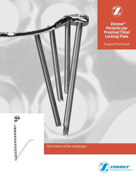
Zimmer ®<strong>Periarticular</strong><strong>Proximal</strong> <strong>Tibial</strong><strong>Locking</strong> <strong>Plate</strong>Surgical TechniqueThe Science of the Landscape
Zimmer <strong>Periarticular</strong> <strong>Proximal</strong> <strong>Tibial</strong> <strong>Locking</strong> <strong>Plate</strong> Surgical Technique1Surgical TechniqueDeveloped in conjunction withStephen K. Benirschke, M.D.Professor, Department ofOrthopaedics and Sports MedicineUniversity of Washington,Harborview Medical CenterSeattle, WashingtonPaul J. Duwelius, M.D.Adjunct Associate ProfessorOrthopaedicsOregon Health Sciences UniversityClinical AttendingSt. Vincent Hospital & Medical CenterPortland, OregonJames A. Goulet, M.D.Professor and DirectorSection of Orthopaedic TraumaDepartment of Orthopaedic SurgeryThe University of Michigan HospitalsAnn Arbor, MichiganDavid A. Templeman, M.D.Associate ProfessorOrthopaedic SurgeryUniversity of MinnesotaStaff, Hennepin County Medical CenterMinneapolis, MinnesotaRobert A. Winquist, M.D.Clinical Professor,Department of OrthopaedicsUniversity of WashingtonOrthopaedic SurgeonSwedish Hospital and Medical CenterSeattle, WashingtonTable of ContentsIntroduction 2<strong>Locking</strong> Screw Technology 2<strong>Locking</strong> <strong>Plate</strong> Technology 2<strong>Plate</strong> Features 3Indications 3Fracture Classification 3Surgical Techniquefor the <strong>Periarticular</strong> 5.5mm <strong>Proximal</strong> <strong>Tibial</strong> <strong>Locking</strong> <strong>Plate</strong> 4Required Instrumentation 4Preoperative Preparation 4Surgical Approach 4Fracture Reduction 6<strong>Plate</strong> Positioning 6Screw Trajectory 9Fracture Fixation 9Wound Closure 16Postoperative Treatment 16Implant Removal 16Instruments and Implants 17Order Information 20Surgical Techniquefor the <strong>Periarticular</strong> 3.5mm <strong>Proximal</strong> <strong>Tibial</strong> <strong>Locking</strong> <strong>Plate</strong> 21Required Instrumentation 21Preoperative Preparation 21Surgical Approach 21Fracture Reduction 22<strong>Plate</strong> Positioning 22Screw Trajectory 24Fracture Fixation 25Wound Closure 30Postoperative Treatment 30Implant Removal 30Instruments and Implants 31Order Information 34
2 Zimmer <strong>Periarticular</strong> <strong>Proximal</strong> <strong>Tibial</strong> <strong>Locking</strong> <strong>Plate</strong> Surgical TechniqueIntroductionThe Zimmer <strong>Periarticular</strong> <strong>Locking</strong><strong>Plate</strong> System combines locking screwtechnology with periarticular platesto create fixed-angle constructs foruse in comminuted fractures or wheredeficient bone stock or poor bonequality is encountered. The fixedangleplate/screw device can be usedin osteopenic bone and other areaswhere traditional screw fixation may becompromised.The <strong>Periarticular</strong> <strong>Locking</strong> <strong>Plate</strong>s willaccommodate standard screws, as wellas locking screws with threaded heads.When necessary, interfragmentarycompression can be achievedusing standard screws in the dualcompression slots.Cannulated screws and instrumentsallow provisional fixation with guidepins in the metaphysis. This helpsensure that the threaded locking screwheads align properly with the threadedplate holes.All plate configurations contain lockingscrew holes in the plate head, andalternating locking and compressionscrew slots in the shaft.<strong>Locking</strong> Screw TechnologyThe heads of the locking screwscontain male threads while the holesin the plates contain female threads.This allows the screw head to bethreaded into the plate hole, lockingthe screw into the plate. This technicalinnovation provides the ability to createa fixed-angle construct while usingfamiliar plating techniques.<strong>Locking</strong> <strong>Plate</strong> TechnologyBy using locking screws in a bone plate,a fixed-angle construct is created. Inosteopenic bone or fractures withmultiple fragments, secure bonepurchase with conventional screws maybe compromised. The locking screwsdo not rely on bone/plate compressionto resist patient load, but functionsimilarly to multiple small angledblade plates. In osteopenic bone orcomminuted fractures, the ability tolock screws into a fixed-angle constructis imperative.By combining locking screw holes withcompression screw slots in the shaft,the plate can be used as both a lockingdevice and a fracture compressiondevice. If compression is desired, itmust be achieved first by inserting thestandard screws in the compressionscrew slots before inserting anylocking screws.The locking plate design does notrequire compression between the plateand bone to accommodate loading.Therefore, purchase of the screws inthe bone can be achieved with a threadprofile that is shallower than that oftraditional screws. The shallow threadprofile, in turn, allows for screws witha large core diameter to accommodateloading with improved bending andshear strength.
Zimmer <strong>Periarticular</strong> <strong>Proximal</strong> <strong>Tibial</strong> <strong>Locking</strong> <strong>Plate</strong> Surgical Technique3<strong>Plate</strong> Features• Anatomically contoured platesare precontoured to createa fit that requires little or noadditional bending and helps withmetaphyseal/diaphyseal reduction• The low profile plate facilitatesfixation without impinging on softtissue• The plate can be used to control amedial fracture fragmentFracture ClassificationThe OTA/AO classification for longbone fractures is divided into threegeneral groups each with threesubgroups. The groups are extraarticular,partial articular, and complexarticular, and the subgroups reflect thedegree of metaphyseal comminution.3.5mm <strong>Proximal</strong> <strong>Tibial</strong> <strong>Locking</strong> <strong>Plate</strong>.Refer to the OTA/AO ComprehensiveClassification of Fractures of LongBones, or the Schatzker classificationbelow for more information.5.5mm <strong>Proximal</strong> <strong>Tibial</strong> <strong>Locking</strong> <strong>Plate</strong>.• 3.5mm <strong>Proximal</strong> Lateral <strong>Tibial</strong><strong>Locking</strong> <strong>Plate</strong>s are available in sixlengths, from 6 hole (104mm ) to 16hole (224mm)• 5.5mm <strong>Proximal</strong> Lateral <strong>Tibial</strong><strong>Locking</strong> <strong>Plate</strong>s are available in sixlengths, from 4 hole (97mm ) to 14hole (250mm)• Dual compression slots willaccommodate periarticular screwsor conventional stainless steelscrews and allow bi-directionalcompressionThe anatomical shapeof the head of the platematches the shape ofthe proximal tibiaMultiple locking holesin the plate head allowplacement of the screwsto capture fragmentsThick-to-thin plateprofiles make the platesautocontourable• The last diaphyseal plate hole isdesigned to accommodate thetension device (00-4817-000-05)IndicationsThe <strong>Periarticular</strong> <strong>Locking</strong> <strong>Plate</strong>System is indicated for temporaryinternal fixation and stabilization ofosteotomies and fractures, including:• Comminuted fractures• Supracondylar fractures• Intra-articular and extra-articularcondylar fracturesThe plate shaft designallows for a minimallyinvasive technique withsubmuscular passage ofthe plateFig. 1. Zimmer <strong>Periarticular</strong> <strong>Proximal</strong> <strong>Tibial</strong> <strong>Locking</strong> <strong>Plate</strong> features.• Fractures in osteopenic bone• Nonunions• Malunions
4 Zimmer <strong>Periarticular</strong> <strong>Proximal</strong> <strong>Tibial</strong> <strong>Locking</strong> <strong>Plate</strong> Surgical TechniqueSurgical Techniquefor the <strong>Periarticular</strong> 5.5mm<strong>Proximal</strong> <strong>Tibial</strong> <strong>Locking</strong> <strong>Plate</strong>Required InstrumentationThe following sets may be required forapplication of the 5.5mm <strong>Periarticular</strong><strong>Locking</strong> <strong>Proximal</strong> Tibia <strong>Plate</strong>s:• Standard Screw Set• Basic Instrument Set• Basic Forcep Set• 5.5mm/4.5mm <strong>Locking</strong> Screw andInstrument Set• 5.5mm <strong>Locking</strong> <strong>Proximal</strong> Tibia <strong>Plate</strong>and Standard Jig Set• Linear Bone ClampsPreoperative PreparationAfter assessing the fractureradiographically and preparing apreoperative plan, place the patient inthe supine position on a radiolucenttable. Be sure that the fluoroscope canbe positioned to visualize the proximaltibia in both the lateral and Anterior/Posterior (A/P) views.Pre-operative planning using A/P andM/L templating will allow assessmentof the ability of the lateral plate tocapture and adequately stabilizeany medial fragments. If adequatereduction or fixation is not feasible, amedial buttress plate should also beconsidered.Surgical ApproachThe patient is positioned supine on aradiolucent operating table.A straight lateral parapatellar incisionis made (Fig. 2). This incision can beextended proximally and/or distallyas more exposure is required. Thedissection should go straight downto the bone by detaching the anteriorcompartment muscle origins andsplitting the fibers of the iliotibial tract.The knee joint is then opened belowthe lateral meniscus in order to get agood view of the articular surface.Do not dissect across the tibialtuberosity – unless absolutelynecessary – the soft tissue coverage onthe medial side is very delicate. Takecare not to place incisions over theproposed sites of implants, or wherethere is risk of devitalizing sensitivestructures.When treating fractures witha bicondylar component, anadditional posteromedial incision isrecommended to ensure anatomicreduction of the medial cortex (Fig. 3).Use of the linear bone clamps greatlyfacilitates reduction of this type offracture (Fig. 4).Fig. 2 Fig. 3
Zimmer <strong>Periarticular</strong> <strong>Proximal</strong> <strong>Tibial</strong> <strong>Locking</strong> <strong>Plate</strong> Surgical Technique5Fig. 4
6 Zimmer <strong>Periarticular</strong> <strong>Proximal</strong> <strong>Tibial</strong> <strong>Locking</strong> <strong>Plate</strong> Surgical TechniqueFracture ReductionIt is imperative that accurate reductionof the fracture be obtained prior to andmaintained during application of theproximal tibial plate.Reduce the intra-articular fragmentsusing linear bone clamps or Kirschnerwires to temporarily hold the reduction.Use lag screws to secure the intraarticularfragments. To help avoidinserting the lag screws where theywill interfere with the plate placement,hold the plate on the bone in itsapproximate position. Then insert thelag screws as needed – the lag screwscan often be placed through the plateusing cannulated conical screws, ormay be inserted in subchondral boneproximal to the plate.Fig. 5Central <strong>Proximal</strong> HoleStrut Screw Hole<strong>Plate</strong> PositioningHold the appropriate (left or right)Metaphyseal Jig (Fig. 5) on the selectedplate and finger tighten the set screw.Insert the 5.5mm Standard Jig Sleeveinto the CENTRAL PROXIMAL hole ofthe jig (Fig. 6) and thread the 3.2mmStandard Cannula into the plate hole(Fig. 7) through the Jig Sleeve.NOTE: The Cannula Inserter may beused to tighten cannulas.Fig. 6Cannula InserterFig. 7
Zimmer <strong>Periarticular</strong> <strong>Proximal</strong> <strong>Tibial</strong> <strong>Locking</strong> <strong>Plate</strong> Surgical Technique7Before placing the plate on the bone,insert additional 5.5mm Standard JigSleeves into each of the most proximalholes in the Metaphyseal Jig, thenthread a 3.2mm Standard Cannulainto the plate (Fig. 8) through each ofthe sleeves. It is easier to thread thecannulas into the plate holes beforethe plate is applied to the bone. Thecannulas can be used as handles toposition the plate.Use this construct to place the initial3.2mm Drill Tip Guide Wire in themetaphysis. Check plate placement –visually and fluoroscopically to ensurethat the plate is positioned correctlyon the metaphysis of the bone. UseA/P and lateral fluoroscopic images toposition the plate. Note: The position ofthe plate on the bone must be verifiedbecause there is a tendency to placethe distal end of the plate too posterioron the tibial shaft. Posterior placementcan cause the locking screws to beplaced at a tangent and can result ininsufficient holding strength. Becausethe tibial shaft may not be alignedwith the proximal fragment, the platehead should be used to determine theappropriate placement of the plate.The plate head should conform to theshape of the intact or reconstructedproximal tibia. This will determine thealignment of the shaft.Fig. 8WARNING: Do not contour or bend theplate at or near a threaded hole, asdoing so may deform the threaded holeand cause incompatibility with thelocking screw.Hold the plate in the desired position(Fig. 9) and insert a 3.2mm Drill TipGuide Wire through the central GuideWire Cannula in the head of the plateuntil the tip engages the oppositecortical wall. Use the fluoroscope toconfirm the position of the wire in boththe A/P and lateral planes. Adjust thewire location if necessary. If preferred,use a linear bone clamp or bonereduction instrument to secure the plate.Fig. 9
8 Zimmer <strong>Periarticular</strong> <strong>Proximal</strong> <strong>Tibial</strong> <strong>Locking</strong> <strong>Plate</strong> Surgical TechniqueWhen the first wire is satisfactory,adjust the plate rotation, if necessary.The next step is to align the plateshaft with the tibial shaft. Insert a3.7mm cannula into the most distalplate shaft hole. Use the 3.7mm drillbit through the cannula. Make certainunder A/P and lateral fluoroscopythat the plate shaft and tibial shaftare aligned properly. Measure for the4.5mm locking screw length using the5.5mm/4.5mm standard locking screwdepth gauge. Insert the 4.5mm lockingscrew. Then insert additional 3.2mmDrill Tip Guide Wires (Fig. 10) throughthe other proximal Guide Wire Cannulasto help prevent rotation of the plate.If desired, after removal of themetaphyseal jig, additional 1.6mmDrill Tip Guide Wires can be insertedthrough the proximal K-wire holes tofurther stabilize the plate (Fig. 11).Use the fluoroscope for both A/P andlateral views to confirm the position ofthe plate head, shaft, and guide wires.The guide wires should be parallel tothe joint line.Fig. 10 Fig. 11
Zimmer <strong>Periarticular</strong> <strong>Proximal</strong> <strong>Tibial</strong> <strong>Locking</strong> <strong>Plate</strong> Surgical Technique9Screw TrajectoryFracture FixationMetaphyseal Screw FixationOnce the plate is properly positioned,slide the 5.5mm Cannulated ScrewDepth Gauge (Fig. 12) over the guidewires to measure for the screw lengths.The tip of the gauge must contactthe end of the guide wire cannula foran accurate measurement. This willposition the tip of the screw at the tipof the guide wire. Read the properscrew length from the guide.Predrilling and tapping are typically notnecessary as the flutes of the screwsare self-drilling and self-tapping. If thebone is dense, the lateral cortex can bepredrilled using the 4.7mm CannulatedDrill and, if necessary, tapped using the5.5mm Cannulated Screw Tap.NOTE: If required, lag screw reductionof a fragment or compression of thearticular surface must be accomplishedbefore inserting any locking screws.The 5.5mm Cannulated Conical Screwscan be used for lag screw fixation.Fig. 12
10 Zimmer <strong>Periarticular</strong> <strong>Proximal</strong> <strong>Tibial</strong> <strong>Locking</strong> <strong>Plate</strong> Surgical TechniqueSlide the Screwdriver Stop Ring ontothe screwdriver shaft and place it atthe level of the black ring etched on thedriver shaft (Fig. 13). Before the BlueStop Ring approaches the top of the JigSleeve, power insertion should stop.Screws must be seated by hand. TheScrewdriver Stop Ring is intended to bea visual cue to stop power insertion ofthe locking screws.Remove the Guide Wire Cannulas anduse the 5.0mm Hex Cannulated Driver(Fig. 14) to insert a 5.5mm CannulatedConical or 5.5mm Cannulated <strong>Locking</strong>Screw over each of the guide wires andinto the three proximal holes. Sleevesand cannulas may be inserted into thetwo additional proximal plate holes iflocked screws are necessary in theseholes. Follow the same procedure foreach proximal screw.Fig. 13NOTE: A screwdriver shaft can beused to loosely insert the screw underpower, but the final seating mustbe accomplished by hand to avoidcross-threading of the screws in theplate holes or breakage of the screw ordriver.NOTE: Screws inserted into the secondrow of metaphyseal holes should beless than 80mm in length to avoidinterference with the other screws.Be sure that all screws are securelytightened.NOTE: If the plate shifts during screwinsertion, all the pins and screws mustbe removed and reinserted for thescrews to lock properly to the plate.NOTE: If a plate screw impinges onone of the intra-articular lag screws,the lag screw must be removed andrepositioned.Fig. 14
Zimmer <strong>Periarticular</strong> <strong>Proximal</strong> <strong>Tibial</strong> <strong>Locking</strong> <strong>Plate</strong> Surgical Technique11Use direct or indirect reductiontechniques to reduce the proximal tibiato the shaft. Confirm that the leg is inproper rotation. Temporarily securethe plate shaft to the bone with plateholding forceps, a nonlocking screw orthe 5.5mm <strong>Plate</strong> Reduction Instrument.If lag screws will be used through someof the holes in the shaft, insert the firstlag screw to reduce the plate to thebone.Shaft FixationIf both locking and nonlockingscrews will be used in the shaft, thenonlocking screws must be insertedfirst. Insert standard cortical screwsthrough the compression slots in theplate as desired.Apply the appropriate drill guide(Fig. 15) (4.5mm/3.2mm Double DrillGuide, 4.5mm Universal Drill Guide,4.5mm Compression Drill Guide or6.5mm/3.2mm Double Drill Guide)to one of the nonlocking slots in theshaft. Use the 3.2mm Standard Drill(Fig. 16) to drill through both cortices.Use the Depth Gauge to measure theFig. 15Fig. 16
12 Zimmer <strong>Periarticular</strong> <strong>Proximal</strong> <strong>Tibial</strong> <strong>Locking</strong> <strong>Plate</strong> Surgical Techniqueappropriate screw length (Fig. 17). Theninsert a self-tapping lag screw (Fig. 18).Check the position of the screw withthe fluoroscope. Repeat this procedurefor each of the standard screws to beinserted.Fig 17Fig 18
Zimmer <strong>Periarticular</strong> <strong>Proximal</strong> <strong>Tibial</strong> <strong>Locking</strong> <strong>Plate</strong> Surgical Technique13To insert locking screws, thread the3.7mm Standard Cannula into the mostproximal shaft locking hole of the plate(Fig. 19). Use the 3.7mm Standard Drillthrough the cannula to drill a pilot hole(Fig. 20). Check the depth and positionof the drill with fluoroscopic images.Fig. 19Fig. 20
14 Zimmer <strong>Periarticular</strong> <strong>Proximal</strong> <strong>Tibial</strong> <strong>Locking</strong> <strong>Plate</strong> Surgical TechniqueRemove the cannula and use theDepth Gauge (Fig. 21) to measure theappropriate screw length. Then insertthe locking screw (Fig. 22).Tapping is typically not necessary asthe flutes of the screws are self-drillingand self-tapping. If the bone is dense,the lateral cortex can be tapped usingthe 4.5mm <strong>Locking</strong> Screw Tap.Insert additional locking screws asdesired.Fig. 21Fig. 22
Zimmer <strong>Periarticular</strong> <strong>Proximal</strong> <strong>Tibial</strong> <strong>Locking</strong> <strong>Plate</strong> Surgical Technique15Strut Screw FixationA locking strut screw can be insertedinto the plate to support a medialfragment. Insert a 5.5mm Jig Sleeveand a 3.2mm Standard Cannula (Fig.23) into the oblique locking hole. Theninsert a 3.2mm Drill Tip Guide Wirethrough the Cannula (Fig. 24) until thetip engages the medial cortical wall.Use the fluoroscope to confirm theposition of the wire in both the A/P andlateral planes.NOTE: To avoid interference with otherscrews, the Strut Screw should be80mm in length or shorter.Fig. 23Fig. 24
16 Zimmer <strong>Periarticular</strong> <strong>Proximal</strong> <strong>Tibial</strong> <strong>Locking</strong> <strong>Plate</strong> Surgical TechniqueRemove the Guide Wire Cannula anduse the 5.0mm Hex Cannulated Driver(Fig. 25) to insert a Cannulated Conicalor <strong>Locking</strong> Screw over the guide wire.Make a final check of the limbalignment and fracture reduction. Thenmake sure that all locking screws in thehead and shaft are securely tightenedbefore closing.Wound ClosureUse the appropriate method forsurgical closure of the incision.Postoperative TreatmentPostoperative treatment withlocking plates does not differ fromconventional open reduction internalfixation (ORIF) procedures. Limitedweight-bearing and early knee motionare recommended.Fig. 25Implant RemovalTo remove locking screws, use the largehexagonal screwdriver, 5.0mm hex tofirst unlock all screws from the plateand then remove screws completely.Do not use the Forward Captive Driversfor screw removal.Please refer to the package insertfor product information, includingcontraindications, warnings, andprecautionary information.
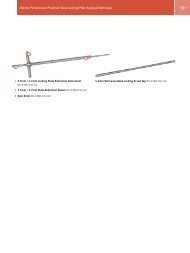
Zimmer <strong>Periarticular</strong> <strong>Proximal</strong> <strong>Tibial</strong> <strong>Locking</strong> <strong>Plate</strong> Surgical Technique17Instrument and Implants5.5mm <strong>Proximal</strong> Lateral <strong>Tibial</strong> <strong>Plate</strong> Jig,Right 00-2360-091-01, Left 00-2360-091-025.5mm/4.5mm Standard Jig Sleeve 00-2360-090-043.2mm Standard Cannula 00-2360-021-32Cannula Inserter 00-2360-088-003.2mm Standard Drill Tip Guide Wire 00-2360-033-32Guide Wire Inserter 00-2360-085-005.5mm Cannulated <strong>Locking</strong> Screw Depth Gauge00-2360-041-554.7mm Std Cannulated Drill 00-2360-071-47
18 Zimmer <strong>Periarticular</strong> <strong>Proximal</strong> <strong>Tibial</strong> <strong>Locking</strong> <strong>Plate</strong> Surgical Technique5.0mm Hex Std Cannulated Screwdriver 00-2360-066-50 Modular Handle 00-2360-086-003.7mm Standard Cannula 00-2360-020-373.7mm Std Drill 00-2360-225-374.5mm <strong>Locking</strong> Screw Standard Depth Gauge00-2360-040-454.5mm <strong>Locking</strong> Screw Tap 00-2360-053-455.0mm Hex Std Screwdriver 00-2360-065-505.0mm Screwdriver Stop Ring 00-2360-065-05