750-634 Manual - MarInfo
750-634 Manual - MarInfo
750-634 Manual - MarInfo

You also want an ePaper? Increase the reach of your titles
YUMPU automatically turns print PDFs into web optimized ePapers that Google loves.
Fieldbus IndependentI/O ModulesIncremental Encoder Interface<strong>750</strong>-<strong>634</strong><strong>Manual</strong>Version 1.0.3
ii • GeneralCopyright © 2006 by WAGO Kontakttechnik GmbH & Co. KGAll rights reserved.WAGO Kontakttechnik GmbH & Co. KGHansastraße 27D-32423 MindenPhone: +49 (0) 571/8 87 – 0Fax: +49 (0) 571/8 87 – 1 69E-Mail: info@wago.comWeb: http://www.wago.comTechnical SupportPhone: +49 (0) 571/8 87 – 5 55Fax: +49 (0) 571/8 87 – 85 55E-Mail: support@wago.comEvery conceivable measure has been taken to ensure the correctness and completenessof this documentation. However, as errors can never be fully excluded,we would appreciate any information or ideas at any time.E-Mail:documentation@wago.comWe wish to point out that the software and hardware terms as well as thetrademarks of companies used and/or mentioned in the present manual aregenerally trademark or patent protected.WAGO-I/O-SYSTEM <strong>750</strong>I/O Modules
Content • iiiCONTENT1 Important Comments .................................................................................41.1 Legal Principles........................................................................................41.1.1 Copyright .............................................................................................41.1.2 Personnel Qualification .......................................................................41.1.3 Intended Use ........................................................................................41.2 Symbols ....................................................................................................51.3 Number Notation......................................................................................51.4 Safety Notes .............................................................................................61.5 Scope ........................................................................................................62 I/O Modules .................................................................................................72.1 Special Modules .......................................................................................72.1.1 <strong>750</strong>-<strong>634</strong> [Incremental Encoder Interface]............................................72.1.1.1 View................................................................................................72.1.1.2 Description......................................................................................72.1.1.3 Display Elements ............................................................................92.1.1.4 Schematic Diagram.........................................................................92.1.1.5 Technical Data ..............................................................................102.1.1.6 Functional Description..................................................................112.1.1.7 Process Image ...............................................................................11WAGO-I/O-SYSTEM <strong>750</strong>I/O Modules
4 • Important CommentsLegal Principles1 Important Comments1.1 Legal Principles1.1.1 CopyrightTo ensure fast installation and start-up of the units described in this manual,we strongly recommend that the following information and explanations arecarefully read and abided by.This manual is copyrighted, together with all figures and illustrationscontained therein. Any use of this manual which infringes the copyrightprovisions stipulated herein, is not permitted. Reproduction, translation andelectronic and photo-technical archiving and amendments require the writtenconsent of WAGO Kontakttechnik GmbH & Co. KG. Non-observance willentail the right of claims for damages.WAGO Kontakttechnik GmbH & Co. KG reserves the right to performmodifications allowed by technical progress. In case of grant of a patent orlegal protection of utility patents all rights are reserved by WAGOKontakttechnik GmbH & Co. KG. Products of other manufacturers are alwaysnamed without referring to patent rights. The existence of such rights cantherefore not be ruled out.1.1.2 Personnel Qualification1.1.3 Intended UseThe use of the product detailed in this manual is exclusively geared tospecialists having qualifications in PLC programming, electrical specialists orpersons instructed by electrical specialists who are also familiar with the validstandards. WAGO Kontakttechnik GmbH & Co. KG declines all liabilityresulting from improper action and damage to WAGO products and third partyproducts due to non-observance of the information contained in this manual.For each individual application, the components supplied are to work with adedicated hardware and software configuration. Modifications are onlypermitted within the framework of the possibilities documented in themanuals. All other changes to the hardware and/or software and the nonconforminguse of the components entail the exclusion of liability on part ofWAGO Kontakttechnik GmbH & Co. KG.Please direct any requirements pertaining to a modified and/or new hardwareor software configuration directly to WAGO Kontakttechnik GmbH & Co.KG.WAGO-I/O-SYSTEM <strong>750</strong>I/O Modules
Important Comments • 5Symbols1.2 SymbolsDangerAlways abide by this information to protect persons from injury.WarningAlways abide by this information to prevent damage to the device.AttentionMarginal conditions must always be observed to ensure smooth operation.ESD (Electrostatic Discharge)Warning of damage to the components by electrostatic discharge. Observethe precautionary measure for handling components at risk.NoteRoutines or advice for efficient use of the device and software optimization.More informationReferences on additional literature, manuals, data sheets and INTERNETpages1.3 Number NotationNumber Code Example NoteDecimal 100 normal notationHexadecimal 0x64 C notationBinary'100''0110.0100'Within ',Nibble separated with dotsWAGO-I/O-SYSTEM <strong>750</strong>I/O Modules
6 • Important CommentsSafety Notes1.4 Safety NotesWarningSwitch off the system prior to working on bus modules!In the event of deformed contacts, the module in question is to be replaced, asits functionality can no longer be ensured on a long-term basis.The components are not resistant against materials having seeping andinsulating properties. Belonging to this group of materials is: e.g. aerosols,silicones, triglycerides (found in some hand creams).If it cannot be ruled out that these materials appear in the componentenvironment, then additional measures are to be taken:- installation of the components into an appropriate enclosure- handling of the components only with clean tools and materials.AttentionCleaning of soiled contacts may only be done with ethyl alcohol and leathercloths. Thereby, the ESD information is to be regarded.Do not use any contact spray. The spray may impair the functioning of thecontact area.The WAGO-I/O-SYSTEM <strong>750</strong> and its components are an open system. Itmust only be assembled in housings, cabinets or in electrical operationrooms. Access must only be given via a key or tool to authorized qualifiedpersonnel.The relevant valid and applicable standards and guidelines concerning theinstallation of switch boxes are to be observed.ESD (Electrostatic Discharge)The modules are equipped with electronic components that may be destroyedby electrostatic discharge. When handling the modules, ensure that theenvironment (persons, workplace and packing) is well grounded. Avoidtouching conductive components, e.g. gold contacts.1.5 ScopeThis manual describes the Module <strong>750</strong>-<strong>634</strong> Incremental Encoder Interface ofthe modular WAGO-I/O-SYSTEM <strong>750</strong>.Handling, assembly and start-up are described in the manual of the FieldbusCoupler. Therefore this documentation is valid only in the connection with theappropriate manual.WAGO-I/O-SYSTEM <strong>750</strong>I/O Modules
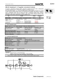
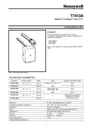
<strong>750</strong>-<strong>634</strong> [Incremental Encoder Interface] • 7View2 I/O Modules2.1 Special Modules2.1.1 <strong>750</strong>-<strong>634</strong> [Incremental Encoder Interface]Incremental Encoder Interface2.1.1.1 ViewAC13 14ABBA+ +B24V0V 0V0VCSCshield (screen)<strong>750</strong>-<strong>634</strong>power jumper contactsFig. 2.1.1-1: Incremental Encoder Interface <strong>750</strong>-<strong>634</strong>g0<strong>634</strong>00e2.1.1.2 DescriptionThe I/O module is an interface for the direct connection of any 24 Vincremental encoders. A 16-bit counter with quadrature decoder and a 16-bitlatch for the zero pulse can be read, set or activated. The counter status istransferred rapidly and is not susceptible to faults to a PC, a PLC or a CNC viathe fieldbus.A period measurement with a resolution of 200 ns is possible.Sensors may be connected using the inputs A, B and C and the supplyconnections 24 V and 0 V and shield (screen).The shield is directly connected to the carrier rail.WAGO-I/O-SYSTEM <strong>750</strong>I/O Modules
8 • <strong>750</strong>-<strong>634</strong> [Incremental Encoder Interface]DescriptionInputFunctionA, B, Quadrature input, DC 24 VIncrement pulse signal channel A or B of the Incremental EncoderCScreen (Shield)Zero reference input, DC 24 VConnection for the encoder line screenThe shield is directly connected to the carrier rail.+24V 24 V supply voltage for the module0VGround for the 24 V supply voltageIndividual green status LEDs indicate the signal status of the A, B and Cinputs.Field and system level are electrically isolated.Any configuration of the specialty modules is possible when designing thefieldbus node. Grouping of module types is not necessary.The field side supply voltage of 24 V and 0 V for the electronic of the sensorsand for the evaluation is derived from adjacent I/O modules or from a supplymodule. The supply voltage for the field side is made automatically throughthe individual I/O modules by means of power jumper contacts.AttentionThis module has no power contacts for ground (earth). For field supply withground (earth) to downstream I/O modules, a supply module will be needed.WarningThe maximum current of the internal power jumper contacts is 10 A. Whenconfiguring the system it is important not to exceed the maximum/sumcurrent. However, if such a case should occur, another supply module mustbe added.The module <strong>750</strong>-<strong>634</strong> can be used with all couplers/controllers of the WAGO-I/O-SYSTEM <strong>750</strong> (except for the economy types <strong>750</strong>-320, -323, -324 and-327).This description is valid for the XXXX2B02..., XXXX2B03..., XXXX2B04...and XXXX2B1A... hardware and software versions, the schematic diagram istested for the version XXXX2B1A.... The version is specified in themanufacturing number, which is part of the lateral marking on the module.WAGO-I/O-SYSTEM <strong>750</strong>I/O Modules
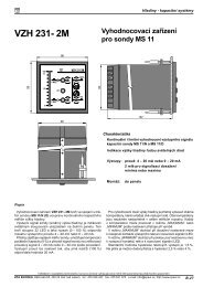
<strong>750</strong>-<strong>634</strong> [Incremental Encoder Interface] • 9Display Elements2.1.1.3 Display ElementsLED Denotation State FunctionABAB13 14CDCAgreenBgreenFig. 2.1.1-2: DisplayElements g0<strong>634</strong>02x CgreenQuadratureInputonoffis equivalent to U > 15 Vis equivalent to U < 5 VQuadrature on is equivalent to U > 15 VInput off is equivalent to U < 5 VZero on is equivalent to U > 15 VreferenceInput off is equivalent to U < 5 V2.1.1.4 Schematic DiagramA24V1256BABC24V270pFA,B,CLogic0V370VC48shield (screen)10nF<strong>750</strong>-<strong>634</strong>Fig. 2.1.1-3:Incremental Encoder Interface <strong>750</strong>-<strong>634</strong>g0<strong>634</strong>01eWAGO-I/O-SYSTEM <strong>750</strong>I/O Modules
10 • <strong>750</strong>-<strong>634</strong> [Incremental Encoder Interface]Technical Data2.1.1.5 Technical DataModule Specific DataSensor connectionSensor operation voltageSignal voltage A, B, CCounterCut off frequencyQuadrature decoderZero impulse latchCommandsA, B, CDC 24 V(1) U > 15 V(0) U < 5V16 Bit binary1 MHz4- fold report16 bitsread, set, enableVoltage supply DC 24 V (- 15 % ... + 20 %)Current consumption max (internal)Current consumption max (field side)IsolationBit width50 mA0 mA (without sensor load)500 V (system/supply)2 x 16 bits data1 x 8 bits Control/Status1 x 8 bits reservedDimensions (mm) W x H x L 12 x 64* x 100*from upper edge of DIN 35 railWeightca. 60 gStandards and Regulations (cf Chapter 2.2 of the Coupler/Controller <strong>Manual</strong>)EMC-Immunity of interference acc. to EN 50082-2 (95)EMV-Emission of interference acc. to EN 50081-2 (94)Approvals (cf Chapter 2.2 of the Coupler/Controller <strong>Manual</strong>)Conformity MarkingMore InformationDetailed references to the approvals are listed in the document "OverviewApprovals WAGO-I/O-SYSTEM <strong>750</strong>", which you can find on the CD ROMELECTRONICC Tools and Docs (Item-No.: 0888-0412)or in the internet under:www.wago.com ! Documentation ! WAGO-I/O-SYSTEM <strong>750</strong> !System DescriptionWAGO-I/O-SYSTEM <strong>750</strong>I/O Modules
<strong>750</strong>-<strong>634</strong> [Incremental Encoder Interface] • 11Functional Description2.1.1.6 Functional Description2.1.1.7 Process ImageTypically, incremental encoders supply two output signals for the encodertrack, both 90° offset. These signals are designated A and B.Usually, incremental encoders have an index track in addition to the two tracksignals. This index track only produces one pulse per one full encoderrevolution. This pulse and the counter reading can be used to determine theabsolute encoder position during rotation. The index pulse has a duration of atrack position pulse. We recommend to always perform the latch process inthe same rotational direction.Using the I/O module <strong>750</strong>-<strong>634</strong>, a 5 byte input and output process image can betransferred to the fieldbus coupler / controller via one logical channel. Thedata sent and received is stored in 2 output bytes (D0, D1) and 5 input bytes(D0, D1, D2, D3, D4). The output bytes D2 ... D4 are reserved and withoutfunction. One control byte (C) and one status byte (S) are used to control thedata flow.AttentionThe representation of the process data of some I/O modules or theirvariations in the process image depends on the fieldbus coupler/-controllerused. Please take this information as well as the particular design of therespective control/status bytes from the section "Fieldbus Specific Design ofthe Process Data" included in the description concerning the process imageof the corresponding coupler/controller.Input DataOutput DataS Status byte C Control byteD0 Counter value byte 0 (LSB) D0 Counter set value byte 0 (LSB)D1 Counter value byte 1 (MSB) D1 Counter set value byte 1(MSB)D2 Signal A, B and C /Cycle duration byte 2 (MSB)D3 Latch value byte 0 (LSB) /Cycle duration byte 0 (LSB)D4 Latch value byte 1 (MSB) /Cycle duration byte 1D2D3D4reservedreservedreservedWAGO-I/O-SYSTEM <strong>750</strong>I/O Modules
12 • <strong>750</strong>-<strong>634</strong> [Incremental Encoder Interface]Process ImageStatus ByteBit 7 Bit 6 Bit 5 Bit 4 Bit 3 Bit 2 Bit 1 Bit 00 0 0 OVER-FLOWUNDER-FLOWCNTSET_ACCRD-PERIOD_QLATC_VALLATC_VAL A zero point (latch) has occurred. The data D3, D4 in the process image match the latched valuein case the cycle duration has not been requested and the bit is set. In order to reactivate the latchinput it is necessary to reset EN_LATC, to wait for the acknowledgement and to reset the bit.RD-The data bytes D2, D3, D4 contain the cycle duration.PERIOD_QCNTSET_ Acknowledge bit for CNT_SETACC Reset if CNT_SET=0UNDER- In the event of an underflow (0 to 65535) of the 16-Bit counter, this bit will be set. A reset willFLOW take place if the counter underruns two third of the measuring range (43690 to 43689) or as soonas an overflow occurs.OVER-FLOW In the event of an overflow (65535 to 0) of the 16-Bit counter, this bit will be set. A reset willtake place if the counter exceeds one third of the measuring range (21845 to 21846) or as soon asan underflow occurs.0 reservedControl ByteBit 7 Bit 6 Bit 5 Bit 4 Bit 3 Bit 2 Bit 1 Bit 00 0 0 0 0 CNT_SETRD-PERIODEN_LATCEN_LATC Zero point (input C) is activated. If the EN_LATC bit is set, the counter value will be stored inthe latch register with the first latch pulse. The following pulses have no effect on the latchregister.RD-PERIOD The cycle duration between positive edges (input A) is measured with a resolution of 200 ns. Ifthe bit is set, the cycle duration will be stored in data bytes D2, D3, D4.CNT_SET With a positive edge, the counter is initialized with the set value.0 reservedSignal A, B and C in Data Byte 2The input signals A, B and C are send in data byte 2 (D2) of the input data, ifbit 1 (RD-PERIOD) in the Control byte is '0'.Signal A, B and C in D2Bit 7 Bit 6 Bit 5 Bit 4 Bit 3 Bit 2 Bit 1 Bit 00 0 Signal A Signal B Signal C 0 0 0WAGO-I/O-SYSTEM <strong>750</strong>I/O Modules
WAGO-I/O-SYSTEM <strong>750</strong>I/O Modules<strong>750</strong>-<strong>634</strong> [Incremental Encoder Interface] • 13Process Image
WAGO Kontakttechnik GmbH & Co. KGPostfach 2880 • D-32385 MindenHansastraße 27 • D-32423 MindenPhone: 05 71/8 87 – 0Fax: 05 71/8 87 – 1 69E-Mail: info@wago.comInternet:http://www.wago.com