S 449 C/2 - Autec-VLT Automotive Equipment
S 449 C/2 - Autec-VLT Automotive Equipment
S 449 C/2 - Autec-VLT Automotive Equipment
- No tags were found...

Create successful ePaper yourself
Turn your PDF publications into a flip-book with our unique Google optimized e-Paper software.
Instructions for useITABLE OF CONTENTSPage1 - GENERAL .....................................................................................................................................................................31.1 - GENERAL SAFETY REGULATIONS ................................................................................................................31.1.1 - STANDARD SAFETY DEVICES ..........................................................................................................31.2 - FIELD OF APPLICATION .................................................................................................................................31.3 - OVERALL DIMENSIONS ..................................................................................................................................31.4 - TECHNICAL DATA .............................................................................................................................................42 - HANDLING AND LIFTING ...........................................................................................................................................43 - STARTUP .....................................................................................................................................................................43.1 - ANCHORING ......................................................................................................................................................43.2 - ELECTRICAL CONNECTION ...........................................................................................................................43.3 - FLANGE MOUNTING .........................................................................................................................................53.4 - WHEEL GUARD ASSEMBLY AND ADJUSTMENT (OPTIONAL) .....................................................................53.5 - WD SPACER .....................................................................................................................................................54 - CONTROLS AND COMPONENTS ..............................................................................................................................54.1 - MANUAL DISTANCE MEASUREMENT GAUGE .............................................................................................54.2 - KEYBOARD AND DISPLAY ...............................................................................................................................64.2.1 FUNCTION MENU MANAGEMENT .................................................................................................................75 - INSTRUCTIONS FOR USE OF THE WHEEL BALANCER ........................................................................................85.1 - SETTING THE WHEEL DIMENSIONS ............................................................................................................85.2 - RECALCULATION OF THE UNBALANCE VALUES ......................................................................................125.3 - MEASUREMENT RESULT .............................................................................................................................125.3.1 - SPLIT FUNCTION (unbalance spread) ...............................................................................................135.3.2 - OUT OF BALANCE OPTIMIZATION ...................................................................................................145.3.3 - AUTOMATIC MINIMISATION OF STATIC UNBALANCE ..................................................................156 - SET-UP ......................................................................................................................................................................166.1 - AUTODIAGNOSTICS .......................................................................................................................................166.2 - AUTOCALIBRATION ........................................................................................................................................177 - ERRORS ....................................................................................................................................................................187.1 - INCONSISTENT UNBALANCE READINGS ..................................................................................................198 - ROUTINE MAINTENANCE ........................................................................................................................................198.1 - REPLACING THE PROTECTION FUSES ......................................................................................................19I 0538 GB - 1
I 0538 GB - 2
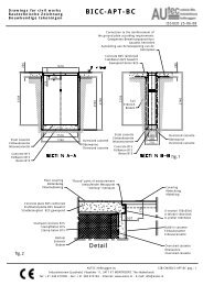
3.3 - Flange mountingThe wheel balancer is supplied complete with cone flangesfor fixing wheels with a central hole. Other optional flangescan be mounted:a) Remove the threaded end-piece A after unscrewing thescrew B.b) Mount the new flange (see attached sheets).Note: CAREFULLY CLEAN THE COUPLINGSURFACES BEFORE PERFORMING ANYOPERATION.33.4 - Wheel guard assembly and adjustment (optional)a) Fasten the components to the base as illustrated in the specific exploded drawing.b) N.b.: The tip of the microswitch must fit into the relative seat when the guard is closed.Note: Do not lean on the guard during the wheel balancing cycle.3.5 - WD SpacerWhen balancing very wide wheels (9”), there is not enough space to turn the distance gauge. To move thewheel away from the machine side, fit the WD spacer on the flange body and secure it with the standard issuenuts. When centring the wheel with cone from the inside, mount the DC spacer to obtain spring thrust.DC WD Cone3aSpring4 - Controls and components4.1 - Manual distance measurement gaugeThis gauge serves to manually measure the distance between the point of application of the counterweight and themachine.I 0538 GB - 5
4.2.1 - Function menu managementMENUENTERSee chapter on unbalance optimisationENTERdiametermm/inchENTERCONFIRMENTERmm/inchwidthENTERCONFIRMENTERstart from guardclosingENTERCONFIRMENTERapprox. -5 g or0.1-0.25 ozENTERCONFIRMENTERENTERSee chapter on AUTODIAGNOSTICSENTERSee chapter on AUTOCALIBRATIONENTERg/oz unit ofmeasureunbalanceENTERCONFIRMSTOPRETURN TO MEASUREMENT FRAMEI 0215 I 0538 0I GB - 7 - 7
EnglishPositioning your projectorChoosing a locationYour room layout or personal preference will dictate which installation location you select. Take intoconsideration the size and position of your screen, the location of a suitable power outlet, as well as the locationand distance between the projector and the rest of your equipment.Your projector is designed to be installed in one of four possible installation locations:1. Front TableSelect this location with the projector placed near thefloor in front of the screen. This is the most commonway to position the projector for quick setup andportability.3. Rear TableSelect this location with the projector placed near thefloor behind the screen.Note that a special rear projection screen is required.*Set Rear Table after you turn the projector on.2. Front CeilingSelect this location with the projector suspendedupside-down from the ceiling in front of the screen.Purchase the BenQ projector ceiling mount kit fromyour dealer to mount your projector on the ceiling.*Set Front Ceiling after you turn the projector on.4. Rear CeilingSelect this location with the projector suspendedupside-down from the ceiling behind the screen.Note that a special rear projection screen and the BenQprojector ceiling mount kit are required for thisinstallation location.*Set Rear Ceiling after you turn the projector on.*To set the projector position:1. Press MENU/EXIT on the projector or remote control and then press /until the SYSTEM SETUP: Basic menu is highlighted.2. Press / to highlight Projector Position and press / until thecorrect position is selected.SYSTEM SETUP: BasicPresentation TimerLanguageProjector PositionAuto Power OffBlank TimerPanel Key LockTimer ControllerSplash ScreenEnglishFront TableDisableDisableOffDisableBenQAnalog RGB MENU Exit12 Positioning your projector
c)Combined balancing: clip-on weight on the inside and hidden adhesiveweight on the outside (Mercedes).The position of the weights can be set.- MEASURING70 gaugeSETTING:a+bd++(Nominal)d+Note: not setting dE as it is automatic, dE = d - 2”.Note: Hold thebutton down for morethan 2 seconds when thevalue of the diameter -dappearson the display.dI 0538 GB - 10
5.2 - Recalculation of the unbalance valuesPress STOP after new setting of the measurement.5.3 - Measurement result9Inside correctionOutside correctionAfter performing a balancing spin, the amounts of unbalance are shown on the digital readouts.The illuminated LEDs 3 and 4 indicate the correct angular position of the wheel to mount the counterweights (12 o’clock).If the unbalance is less than the threshold value selected, is displayed instead of the unbalance value; with FINEthe values below the threshold can be read, selected gram by gram.Note :in the case of wheels with a diameter less than or equal to 13” and at temperature conditions near 0°, the wheelbalancer automatically inserts a special measuring cycle composed of two successive measurements. The accuracy of the unbalance values and the reliability of the wheel balancer remain unchanged. This type of operation isreset each time the wheel balancer is started.I 0538 GB - 12
5.3.1 - SPLIT function (unbalance spread)The SPLIT function is used to position the adhesive weights behind the wheel spokes so that they are not visible. Thisfunction should be used only in the case of static unbalance or where the hidden adhesive weight is to be applied on theoutside. Input the wheel dimensions and do a spin.To start the SPLIT function, input the following data:Display examplebefore the SPLIT functionInput the number of spokes ( 3 ÷ 12 )- Move a spoke at random to the 12 o’clock position1530- Place the first Split unbalance in correction position 11530- Correction position 13015- Set the second split unbalance to correction position 23015- Correction position 2To return to normal unbalance display, press the buttonTo perform a new spin, subsequently press the buttonI 0538 GB - 13
5.3.2 - Out of balance optimization- This function serves to reduce the amount of weight to be added in order to balance the wheel- It is suitable for static unbalance greater than 30 g.- It improves the residual eccentricity of the tyre.ENTER- With a piece of chalk make a reference mark on the flange and the rim- With the aid of a tyre remover, turn the tyre on the rim by 180°- Refit the wheel in such a way that the reference marks on the rim and theflange coincide.- RH display: percentage reduction value- LH display: actual static unbalance value which can be reduced by rotationTYREPOSITIONRIMPOSITION- Mark the two positions of the rim and tyre, and turn the rim on the tyre until thepositions correspond in order to obtain the optimization on the display.ENTERRETURN TO START OF OPTIMISATIONRETURN TO MEASUREMENT FRAMEI 0538 GB - 14
5.3.3 - Automatic minimisation of static unbalanceInitial unbalancePhase shiftPossible approximationsstatic residue static residue static residue static residueWith traditionalwheel balancerChoice with minimumstatic unbalanceThis program is designed to improve the quality of balancing without any mental effort or waste of time by the operator.In fact, using the normal weights available on the market (pitch of 5 in every 5 g) and applying the two counterweightswhich a conventional wheel balancer rounds to the nearest value, a residual static unbalance of up to 4 gmay result. The damage of such approximation is emphasized by the fact that static unbalance is the cause of mostdisturbances on vehicles. This new function automatically indicates the optimum entity of the weights to apply byapproximating them in an “intelligent” way according to their position in order to minimize residual static unbalance.I 0538 GB - 15
6 - Set-up6.1 - AutodiagnosticsDISPLAY TEST- All the LEDs and the displays should light up simultaneously.- On the right-hand display the current position of the wheel is indicatedwith a number from 0 to 127. Turning the wheel in the direction of rotation,the number displayed should increase. Turning the wheel in theopposite direction of rotation the number displayed should decrease.With one full turn of the wheel the number zero should appear only once.- Press:ENTER- Control parameterENTER- Checking parameter for technical serviceENTER- Checking parameter for technical serviceENTEREND OF AUTODIAGNOSTICSSTOPCANCEL AUTODIAGNOSTICS IN ANY PHASE.I 0538 GB - 16
6.2 - AutocalibrationFor autocalibration proceed as follows:- Fit a wheel with steel rim of average dimensions on the shaft. Example 6” x 14” (± 1”)- Set the exact dimensions of the wheel mounted.CAUTION !! Setting incorrect dimensions will result in the machine not being properly calibrated and hence allthe subsequent measurements will be incorrect until a new autocalibration is performed with thecorrect dimensions!!ENTER- Perform a spin under normal conditions.START- Add 100 g. (3.5 oz) on the outside in any angular position.START- Shift the 100 g weight from the outside to the inside keeping the sameangular position.START- Turn the wheel until the 100 g weight is in the 12 o’clock position.ENTEREND OF AUTOCALIBRATIONSTOPCANCEL AUTOCALIBRATION IN ANY PHASE.I 0538 GB - 17
7 - ErrorsDuring machine operation there may be various causes of malfunctioning which, if detected by the microprocessor,are indicated on the display:Black The wheel balancer does not come on. 1. Check proper connection to the mains.2. Check and if necessary replace the fuses on the power board.3. Replace the computer board.Err. 1 No rotation signal. 1. Check belt tautness.2. Check functioning of the phase generator and, in particular, thereset signal.3. Replace the phase generator.4. Replace the computer board.Err. 2Too low speed during measurement.During the unbalance measurementrevolutions, the wheel speed has fallen tobelow 42 rpm.1. Check that a vehicle wheel has been mounted on the wheelbalancer.2. Check belt tautness.3. Check functioning of the phase generator and, in particular, thereset signal.4. Replace the computer board.Err. 3 Too high unbalance. 1. Check the wheel dimension setting.2. Check the sensor connections.3. Run the machine calibration function.4. Mount a wheel with a more or less known unbalance (less than 100grams) and check the machine response.5. Replace the computer board.Err. 4Err. 5Err. 7 /Err. 8 /Err. 9Err. 11Err.14/Err.15/Err.16/Err.17/Err. 18Rotation in opposite direction.After pressing [START], the wheelstarts turning in the opposite direction(anticlockwise).Guard openThe [START] pushbutton was pressedwithout first closing the guard.1. Verify the connection of the UP/DOWN - RESET signals on thephase generator.1. Reset the error.2. Close the guard.3. Verify the function of the protection uSwitch.4. Press the [START] button.NOVRAM parameter read error 1. Repeat machine calibration2. Shut down the machine.3. Wait for at least ~ 1 min.4. Restart the machine and check proper functioning.5. Replace the computer board.Too high speed error.The average spinning speed is greater than240 rpm.1. Check if there is any damage or dirt on the timing disc.2. Check functioning of the phase generator and, in particular, thereset signal.3. Replace the computer board.Unbalance measurement error. 1. Check functioning of the phase generator.2. Check the sensor connections.3. Check the machine earthing connection.4. Mount a wheel with a more or less known unbalance (less than 100grams) and check the machine response.5. Replace the computer board.Err.21 Motor on for more than 15 seconds. 1. Check functioning of the phase generator.2. Check the connections on the power board.3. Replace the computer board.Err.22Err.32/Err.33/Err.34/Err.35/Err.36/Err.37Maximum number of spins possible forthe unbalance measurement has beenexceeded.Errors related to test functions of the wheelbalancer.1. Check that a vehicle wheel has been mounted on the wheelbalancer.2. Check belt tautness.3. Check functioning of the phase generator and, in particular, thereset signal.4. Replace the computer board.1. Cancel the error and continue using the wheel balancer as normal.I 0538 GB - 18
7.1 - Inconsistent unbalance readingsIt may occur that after balancing a wheel, when removing it from the wheel balancer and then remounting it, thewheel is not balanced.This is not the result of an incorrect indication by the machine, but only of incorrect mounting of the wheel on theflange, i.e. in the two mountings the wheel has assumed a different position with respect to shaft axis of the wheelbalancer. If the wheel has been mounted on the flange with screws, it may be that the screws have not been tightenedcorrectly in gradual criss-cross manner one after the other, or (as often occurs) holes have been drilled in thewheel with too wide tolerances.Small errors, up to 10 grams (0.4 oz), are to be considered normal in wheels locked with a cone: the error is normallygreater for wheels locked with screws or studs.If, after balancing, the wheel is still unbalanced when refitted on the vehicle, this could be due to the unbalance ofthe brake drum or very often is due to the screw holes in the rim and the drum drilled with too wide tolerances. In thiscase a readjustment would be advisable using the wheel balancer with the wheel mounted.8 - Routine maintenanceBefore carrying out any operation on the machine, cut the power supply to the machine.8.1 - Replacing the protection fusesA protection fuse is fitted on the power board, accessible by dismantling the weight shelf (see Exploded Drawings). Iffuses require replacement, use ones with an identical current rating.If the fault persists, contact Technical Service.NONE OF THE OTHER MACHINE PARTS REQUIRE MAINTENANCE.I 0538 GB - 19
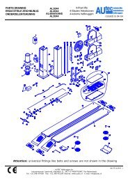
PR 0538 - Recommended spare parts listRSHAFT ASSEMBLYPOWER UNITCODEDESCRIPTION080077004 Rigid belt Poly V181206560 Distance gauge spring511242101 Two pole switch 16A05PR62046Lexan panel86SC61693Computer board67M60192APosition pick-up board with cable86SB72093Cable with microswitch for GP wheel guard86SB72089Cable with microswitch for 34” wheel guard50FG590091-ph Motor 230V/50-60 Hz50FG614561-ph Motor 115V/50-60 Hz020600503 Bearing 6005-2Z181198630 Spring86SZ72076Complete power plate 230V86SZ72078Complete power plate 115V67M70968OPower board 230V67M70968PPower board 115V568001058 Capacitor 10 MF (230V)568003558 Capacitor 35 MF (115V)
Extraordinary maintenanceMTABLE OF CONTENTSPage1 - TO CHANGE SUPPLY VOLTAGE .................................................................................................................................32 - DISTANCE GAUGE CHECK .........................................................................................................................................33 - PIEZO SENSOR ASSEMBLY ........................................................................................................................................44 - TROUBLESHOOTING LOGIC SEQUENCE .................................................................................................................55 - POWER BOARD REPLACEMENT ...............................................................................................................................66 - FUNCTIONING AND ACCURACY TEST .....................................................................................................................77 - WHEEL MEASUREMENT AND SETTING ON THE WHEEL BALANCER .................................................................8M 0538 GB - 1
M 0538 GB - 2
1 - To change supply voltage(See recommended spare lists and power layout diagram)The machine can run on 115 V - 50/60 Hz or 230 V - 50/60Hz.To change the supply voltage, proceed as follows:1) Replace the motor.2)Replace the entire power board or else modify the board as follows:A) Replace the capacitorB) Replace the power board2 - Distance gauge checkCheck that the ruler used for measuring the DISTANCE of the wheels reads 210 mm as measurement of the distancefrom the adapter plane. If the graduated strip is replaced, position it with the line indicating 210 at the fixed index limit(reading point) when the prod coincides with the adapter plane.1Reading point: 210 mm Adapter planeM 0538 GB - 3
3 - Piezo sensor assemblyASSEMBLY INSTRUCTIONSProblems of excessive compensation and out-of-phase sometimes depend on a fault in the piezo measurers.To replace them, proceed as follows:1. Remove the weight shelf.2. Remove nuts 1 and 2 with relative cup springs and washers.3. Back-off screws 3, 4, 6 and 5 then disassemble the various parts.4. Reassemble the various parts without tightening the nuts being careful to follow the correct sequence.N.B.: Mount the piezo units in accordance with the position of the coloured wires shown in the drawing.5. Keeping the spindle perfectly aligned, tighten the nuts 5 and 6 with a spanner, and nuts 3 and 4 by hand (by half aturn with the spanner if necessary).6. Refit the washers, cup springs and nuts 1 and 2. Tighten the nuts fully in order to fully regain the elasticity of thecup springs, then loosen them by half a turn. This will automatically ensure correct preloading on the piezo (a torquewrench can be used set to 400 kg. cm.).7. Cover the piezo units with a generous layer of silicone.(N.B.: For correct operation, insulation of the piezocrystals should be greater than 50 Mohm).8. Reassemble the various parts.9. Again carry out the automatic calibration.232546yellowblueyellowwhite1M 0538 GB - 4
4 - Trouble shooting logic sequenceIs fuse F1 on the power boardin a good state?NOReplace the power boardYESReplace the fuse and power themachineYESDoes F1 work?NODisconnect CN1 on the power board.Replace F1 again and power the machine.Does F1 work?NOYESReplace the computer boardIs the position sensor working?( see AUTODIAGNOSTICS)NOYESReplace the position sensorboardN.B. : Do not remove themounting brackets.Replace the computer boardM 0538 GB - 5
5 - Power board replacement311A22AF1T1CN6WHEELGUARDCN19CN1COMPUTERBOARDCN4MM 0538 GB - 6
6 - Functioning and accuracy testIf not clearly identifiable faults or inaccuracies are encountered, it may be useful to run the functioning and accuracytest.PRELIMINARY CHECKS· Thorough cleaning of the flange and cones· Spring cover sliding· Shaft terminal lockingENCODER TEST (see AUTODIAGNOSTICS)· POS = outside display: 0/127 turning the shaft by handWHEEL BALANCING MACHINE CALIBRATION (see AUTOCALIBRATION)· Use a wheel of average dimensions. Ex.: 6” x 14” (± 1”)· Manually set precise measurements· Perform autocalibrationMACHINE CALIBRATION CHECK1) Mount an average-sized iron wheel (Ex.: 6” x 14” (± 1”) and carefully set the Distance / Diameter / Width.2) Spin 10 consecutive times and measure the repeatability error (normally ± 1 g; acceptable ± 2 g).3) Balance the wheel as well as possible.4) Apply 100 g on the outside; you should have:F.E. = 100 ± 5 F.I. ≤ 5 gr Weight F.E. = vertical down5) Remove the 100 g weight from the outside and apply it to the inside; the following should be true :F.I. = 100 ± 5 F.E. ≤ 5 gr Weight F.I. = vertical down6) If the values are out of tolerance, proceed with autocalibration and repeat points 3), 4), 5).FLANGE CHECKWith the wheel perfectly balanced, tilt 180° and measure the unbalance valuesMAX ERR =Especially for this check, it is advisable to use a sample wheel with known max. unbalance errors caused by centring,which for iron wheels are normally less than 10 g.M 0538 GB - 7
7 - Wheel measurement and setting on the wheel balancerThe need for ever more accurate calibration and the use of the ALU buttonsmakes it important to define how the rimsmust be measured and how the wheel balancer interprets the data set. Hence we indicate how the set dimensionsare automatically changed in order to obtain the distances of the correction planes which are defined as throughplanesfor the centres of gravity of the correction weights. Let us consider a typical rim: The measurement “l” givenas rim width by the manufacturer differs from the distance measured between the correction planes for the rimthickness and the physical dimensions of the counterweight whose centre of gravity is at distance “h” from the restingpoint on the edge of the rim. The wheel balancer automatically corrects the set measurement by adding 2 x h = 6 mmto the measurement. The measurement “b” made with the gauge is normally more accurate even if very similar to themeasurement “l” known by the user. The two measurements differ only by the thickness of the plate, usually about2 mm per side. This minimal difference allows obtaining accurate calibration by indifferently setting the inside width“l” or the outside width “b” of the rim. It is a good rule to add 1/4 inch to the value given by the rim manufacturer. Asregards the ALU functions, the machine performs the following approximations in addition to systematic correction ofthe centre of gravity of the counterweight as seen above.IEa b hNOTE : I = INSIDEE = OUTSIDEIIIEEEa = a preset + ¾”b = b preset - 1 1/2 ”dl = d preset - 1”dE = d preset - 1”a = a presetb = b preset -¾”dl = d presetdE = d preset - 1”a = a preset + ¾”b = b preset -¾”dl = d preset - 1”dE = d preset0 gauge0 CalibroaIdIaEdEa = aI preset - 8 mmb = aE - aIdI = d preset - 1”dE = d preset - 2”0 0gaugeCalibroaIdIaEdEa = aI presetb = aE - aI - 5 mmdI = d presetdE = d preset - 2”0 gaugeaIdaEdEa = aI preset - 8 mmb = aE - aIdI = d presetdE = d preset - 1”M 0538 GB - 8
GIULIANO S.p.A.Via Guerrieri, 6 - 42015 CORREGGIO - ITALYTel. +39. 522. 73.11.11 - Fax. +39. 522. 63.31.09E-mail: giuliano@giuliano.ithttp://www.giuliano.it