APC Smart-UPS X-Series Operation Manual - Edgetch
APC Smart-UPS X-Series Operation Manual - Edgetch
APC Smart-UPS X-Series Operation Manual - Edgetch

You also want an ePaper? Increase the reach of your titles
YUMPU automatically turns print PDFs into web optimized ePapers that Google loves.
<strong>Operation</strong> <strong>Manual</strong><strong>Smart</strong>-<strong>UPS</strong> ® X-<strong>Series</strong><strong>UPS</strong>750 VA1000 VA1500 VA120V230V
SpecificationsOperating ConditionsThis unit is intended for indoor use only. Select a location sturdy enough to support the weight of the unitand External Battery Packs (XLBP).Do not operate the <strong>UPS</strong> where there is excessive dust, or the temperature or humidity are outside thespecified limits.This unit has front and rear air vents. Allow adequate space for proper ventilation.Environmental SpecificationsEnvironmental factors impact battery life. High temperatures, poor utility power, and frequent, shortduration discharges will shorten battery life.For additional specifications, see the <strong>APC</strong> Web site at www.apc.com.TemperatureMaximumElevationHumidityOperating 0° to 40° C (32° to 104° F)StorageOperatingStorage-15° to 45° C (5° to 113° F)charge <strong>UPS</strong> battery every six months3,000 m (10,000 ft)15,000 m (50,000 ft)0% to 95% relative humidity, non-condensingInstallation<strong>UPS</strong>Network Management CardFor <strong>UPS</strong> installation information, see the <strong>Smart</strong>-<strong>UPS</strong> X-<strong>Series</strong> Quick-Start guide that isincluded with the <strong>UPS</strong>. The guide is also available on the enclosed CD and the <strong>APC</strong> Web siteat www.apc.com.For installation information, see the user manual provided with the Network ManagementCard (NMC). The user manual is also available on the <strong>APC</strong> Web site at www.apc.com.External Battery PackFor installation information, see the <strong>Smart</strong>-<strong>UPS</strong> X-<strong>Series</strong> External Battery Pack Installationguide that is included with the external battery pack. The guide is also available on theenclosed CD and the <strong>APC</strong> Web site at www.apc.com.2<strong>Smart</strong>-<strong>UPS</strong> X-<strong>Series</strong> <strong>Operation</strong>
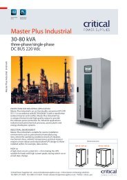
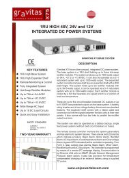
<strong>Operation</strong>Connect Equipment to the <strong>UPS</strong>Note: The <strong>UPS</strong> will charge to 90% capacity in the first three hours of normal operation. Donot expect full battery run capability during this initial charge period.1. Connect equipment to the outlets on the rear panel of the <strong>UPS</strong>. Do not use extension cords, plugequipment directly into the <strong>UPS</strong>.2. Connect the <strong>UPS</strong> to the building utility power. Connect the <strong>UPS</strong> to a two-pole, three-wire,grounded receptacle only.3. Press the ON/OFF button on the front panel of the <strong>UPS</strong> to apply power to the unit and all connectedequipment.4. To use the <strong>UPS</strong> as a master on/off switch, turn on all the equipment that is connected to the <strong>UPS</strong>.See “Controllable Outlet Groups” on page 7 for information on how to use the ControllableOutlet Groups.su0439aBasic ConnectionsSerial port: Connect to a computer to use power management software.USB port: Connect to a computer to use power management software.External Battery Pack connector: Connect external battery packs to provideextended runtime during power outages. The <strong>UPS</strong> can support up to five externalbattery packs.TVSS Ground Screw: The <strong>UPS</strong> features a Transient Voltage Surge-Suppression(TVSS) screw for connecting the ground lead on surge suppression devices such asa telephone and network line protectors. When connecting a grounding cable,disconnect the <strong>UPS</strong> from utility power.<strong>Smart</strong>-<strong>UPS</strong> X-<strong>Series</strong> <strong>Operation</strong>3
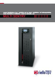
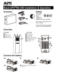
Display InterfaceOverview Online indicator <strong>UPS</strong> Output On/Off button On Battery indicator Fault indicator Replace Battery indicator Display screen UP/DOWN buttons ENTER button ESCAPE button<strong>APC</strong> by SchneiderElectricsu0343aUsing the display interfaceUse UP and DOWN to scroll through the main menu options. Press ENTER to view the sub-menus undereach main menu option. Press ESCAPE to exit a sub-menu and return to a main menu.Standard MenusThe Standard menus are the most commonly used menus for the <strong>UPS</strong>.MenuStatusConfigurationTest & DiagsGeneral FunctionsView basic information about the <strong>UPS</strong>:• Operating mode• Controllable Outlet state, On or Off• Efficiency of the <strong>UPS</strong>• Information about the load• Battery capacity• Estimated runtime• Input and output voltage and frequency• Information about the last transfer to battery power• Self-test resultsConfigure the settings for the <strong>UPS</strong>:• Language• Local power quality: Good, Fair, Poor• Choose Standard or Advanced menus• LCD Display mode, Always On or Power-Saving• Audible alarms• Reset to Factory DefaultsUse the Test & Diags menu to have the <strong>UPS</strong> perform aself-test.4<strong>Smart</strong>-<strong>UPS</strong> X-<strong>Series</strong> <strong>Operation</strong>
MenuAboutGeneral FunctionsDisplay information about this unit:• Unit model number• Serial number• Battery installation date• Suggested battery replacement date• Replacement Battery Cartridge model number• <strong>UPS</strong> firmware versionAdvanced MenusThe Advanced menus provide additional options for the <strong>UPS</strong> and are available only if the displayinterface is configured to use the Advanced Menus.MenuStatusConfigurationControlTest & DiagsLogAboutGeneral FunctionsView detailed information about the <strong>UPS</strong>:•Energy meter• Number of external battery packs connected to the <strong>UPS</strong>• Load current• Status of the Controllable Outlet Groups• Battery voltageConfigure advanced settings for the <strong>UPS</strong>:• <strong>UPS</strong> and Controllable Outlet group delays and settings• High and lower transfer points• Sensitivity settings• Date of last battery replacementControl the <strong>UPS</strong> and Controllable Outlet Groups to turn on,turn off, or rebootPerform a <strong>UPS</strong> alarm test or a runtime calibration testView the event log for information about any changes tothe <strong>UPS</strong> and any faultsView information about the unit:• Hardware version• Software version• NMC information (if applicable)<strong>Smart</strong>-<strong>UPS</strong> X-<strong>Series</strong> <strong>Operation</strong>5
Configuration<strong>UPS</strong> SettingsStart-up SettingsConfigure these settings at initial start-up, using the display interface or <strong>APC</strong> PowerChute ® software.Note: During start-up, use the display interface to configure these settings. If nothing isselected, the until will use the default settings.Function Factory Default Options DescriptionLanguage English • English•French*•German*•Spanish*• Italian*Local powerqualityGeneral SettingsGood• Good•Fair•PoorMenu Type Standard Standard orAdvancedDisplayModeAlways OnAlways On orPower SavingThe language for the display interface.*Language options will vary by model.Select the quality of input utility power.• If Good is selected, the unit will go on batterypower more often to provide the cleanest powersupply to the connected equipment.• If Poor is selected, the <strong>UPS</strong> will tolerate morefluctuations in power and will go on battery powerless often.If unsure of the local power quality, select Good.The advanced menus include all parameters. TheStandard menus display a limited set of menus andoptions.The display may be always on or may be set toautomatically turn on only when using theconfiguration buttons or if an event occurs.Configure these settings at any time, using the display interface or <strong>APC</strong> PowerChute software.Function Factory Default Options DescriptionHigh transferpointLow TransferPoint120 V: 140 VAC 120 V: 140-150 VAC To avoid unnecessary battery usage, set the230 V: 280 VAC 230 V: 280-300 VAC transfer point higher if the utility voltage ischronically high and the connected equipmentis known to work under this condition. Thissetting may also be adjusted using the powerquality setting.120 V: 75 VAC 120 V: 75-85 VAC Set the transfer point lower if the utility230 V: 170 VAC 230 V: 150-170 VAC voltage is chronically low and the connectedequipment can tolerate this condition.Thissetting may also be adjusted using the powerquality setting.6<strong>Smart</strong>-<strong>UPS</strong> X-<strong>Series</strong> <strong>Operation</strong>
Controllable Outlet GroupsOverviewFunction Factory Default Options DescriptionNominal OutputVoltageTransferSensitivityLow BatteryWarningDate of LastBatteryReplacement230 V: 230 VAC 230 V: 220, 230, 240VACThe rear panel of the <strong>UPS</strong> has multiple outlets, some are grouped into Controllable Outlet Groups, allothers are the <strong>UPS</strong> outlets. All of these groups can be configured to turn off, turn on, shut down, andreboot connected equipment, independently of each other.The Controllable Outlet Groups and the <strong>UPS</strong> outlets can be configured to react to power events inspecific ways:• Turn off: Disconnect from power immediately and restart only with a manual command• Turn on: Connect to power immediately• Shutdown: Disconnect power in sequence, and automatically reapply power in sequence whenutility power becomes available• Reboot: Shut down and restartIn addition, the Controllable Outlet Groups and the <strong>UPS</strong> outlets can also:• Turn on or off in a specified sequence• Shut down when various conditions occurSet the nominal output voltage of the <strong>UPS</strong> onbattery. This is available on 230V modelsonly.High High, Low, Medium Specify how sensitive the <strong>UPS</strong> will betowards voltage changes.90 sec 0-300 sec The <strong>UPS</strong> will emit an audible alarm when theremaining runtime has reached this level.Date set at factoryReset this date when the battery module is replaced.Audible Alarm On On/Off The <strong>UPS</strong> will mute all audible alarms if this isset to Off or when the display buttons arepressed.Battery Self-Test IntervalSettingReset to FactoryDefaultOn start-up and • Neverevery 14 days since • Start-up onlythe last test • Frequency of testThe interval at which the <strong>UPS</strong> will execute aself-test.No Yes/No Restore the <strong>UPS</strong> factory default settings.Note: If the Controllable Outlet Groups are not configured, all of the outlets on the unit willstill provide battery back-up power.<strong>Smart</strong>-<strong>UPS</strong> X-<strong>Series</strong> <strong>Operation</strong>7
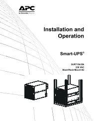
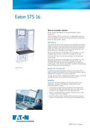
Model-specific Controllable Outlet Groups Controllable Outlet Group(s) <strong>UPS</strong> outlets750VA, 120 V and 230 V.1000 VA, 120 V and 230 V.1500 VA, 120 V and 230 V.su0488asu0487asu0435asu0437asu0436asu0438a8<strong>Smart</strong>-<strong>UPS</strong> X-<strong>Series</strong> <strong>Operation</strong>
Using the Controllable Outlet Groups and <strong>UPS</strong> outletsThe <strong>UPS</strong> outlets function as a master switch. They turn on first when power is applied, shutoff last when there is a power outage and battery run-time has been exhausted.The <strong>UPS</strong> outlets must be turned on for the Controllable Outlet Groups to turn on.1. Connect critical equipment to the <strong>UPS</strong> outlets (except for 1500 VA models; then, connect allcritical equipment to one Controllable Outlet Group.)2. Connect peripheral equipment to the Controllable Outlet Groups.– Nonessential equipment that should shut off quickly in the event of a power outage toconserve battery runtime can be added to a short power-off delay– If equipment has dependent peripherals that must restart or shut down in a specific order, suchas an ethernet switch that must restart before a connected server, connect the devices toseparate groups– Equipment that needs to reboot independently from other equipment should be added to aseparate group3. Use the Configuration menus to configure how the Controllable Outlet Groups will react in theevent of a power outage.Customize the Controllable Outlet Groups and the <strong>UPS</strong> outletsUse the Control menus to change the Controllable Outlet Groups and the <strong>UPS</strong> outlet settings.Function Factory Default Options DescriptionName StringOutlet GroupOutlet Group 1<strong>UPS</strong> Name String <strong>UPS</strong> OutletsEdit these names using an external interface, such as the NetworkManagement Card Web interface.Turn On Delay 0 sec 0-32767 sec The amount of time the <strong>UPS</strong> or ControllableOutlet Group will wait between receiving thecommand to turn on and the actual startup.Turn Off Delay 0 sec 0-32767 sec The amount of time that the <strong>UPS</strong> orControllable Outlet Group will wait betweenreceiving the command to turn off and theactual shut down.Reboot Duration 4 sec 0-32767 sec The amount of time that the <strong>UPS</strong> orControllable Outlet Group must remain offbefore it will restart.Minimum ReturnTimeLoad Shed OnBattery0 sec 0-32767 sec The amount of battery runtime that must beavailable before the <strong>UPS</strong> or ControllableOutlet Group will turn on.Disabled• Shutdown withDelay• Shutdownimmediately• Turn offimmediately• Turn off withdelay• DisabledWhen the unit switches to battery power, the<strong>UPS</strong> can disconnect power to the ControllableOutlet Groups to save runtime.Configure this delay time, use the LOAD SHEDTIME WHEN ON BATTERY setting.<strong>Smart</strong>-<strong>UPS</strong> X-<strong>Series</strong> <strong>Operation</strong>9
Function Factory Default Options DescriptionLoad Shed Timewhen On BatteryLoad Shed OnRuntimeLoad Shed OnRuntimeRemainingLoad Shed onOverloadDisabled 0-32767 sec The amount of time the outlets will function onbattery power before they will turn off.Disabled• Shutdown withdelay• Shutdownimmediately• Turn offimmediately• Turn off withdelay• DisabledWhen the battery runtime falls below thespecified value, the Controllable Outlet Groupwill turn off.Configure this time using the LOAD SHEDRUNTIME REMAINING setting.Disabled 0-32767 sec When the remaining runtime reaches this level,the Controllable Outlet Group will turn off.Disabled• Disabled• Enabled(Applicable only for Controllable OutletGroups, not the <strong>UPS</strong> outlets.) When enabled,the Controllable Outlet Group will turn offimmediately in the event of a power outageand will have to be manually restarted.Network Management Card SettingsThese settings are available only on units that have a Network Management Card (NMC) and are set inthe factory. These settings can only be modified using an external interface, like the NMC web interface.• NMC IP Address Mode• NMC IP Address• NMC Subnet Mask• NMC Default Gateway10<strong>Smart</strong>-<strong>UPS</strong> X-<strong>Series</strong> <strong>Operation</strong>
Emergency Power OffEPO OverviewThe Emergency Power Off (EPO) option is a safety feature that will immediately disconnect allconnected equipment from utility power. The <strong>UPS</strong> will immediately shut down and will not switch tobattery power.The <strong>UPS</strong> must be manually re-started to re-apply power to connected equipment and to the <strong>UPS</strong>. PressON/OFF on the front panel of the unit.Normally open contacts1. If the EPO switch or relay contacts are normally open, insert the wiresfrom the switch or contacts at pins 1 and 2 of the EPO terminal block.Use 16-28 AWG wire.gen0887a2. Secure the wires by tightening the screws.Power will be disconnected to the <strong>UPS</strong> and attached loads if the contacts are closed.Normally closed contacts1. If the EPO switch or relay contacts are normally closed, insert the wiresfrom the switch or contacts at pins 2 and 3 of the EPO terminal block.Use 16-28 AWG wire.2. Insert a wire jumper between pins 1 and 2. Secure the wires bytightening the three screws at position 1, 2, and 3.Power will be disconnected to the <strong>UPS</strong> and attached loads if the contacts are opened.gen0888aNote: The power for operating the EPO circuit is sourced from pin 1. This is an isolated 24 V which cansource only a few milliamps.If the normally closed (NC) EPO configuration is used, the EPO switch or relay should be rated for "dry"circuit applications, the rating should be for low voltage and low current applications. This normallyimplies the contacts are gold-plated.Adhere to all national and local electrical codes when wiring the EPO. Wiring must be performedby a qualified electrician.The EPO interface is a Safety Extra Low Voltage (SELV) circuit. Connect the EPO interface only toother SELV circuits. The EPO interface monitors circuits that have no determined voltage potential.SELV circuits are controlled by a switch or relay properly isolated from utility power. To avoid damageto the <strong>UPS</strong>, do not connect the EPO interface to any circuit other than a SELV circuit.Use one of the following cable types to connect the <strong>UPS</strong> to the EPO switch.• CL2: Class 2 cable for general use.• CL2P: Plenum cable for use in ducts, plenums, and other spaces used for environmental air.• CL2R: Riser cable for use in a vertical run in a floor-to-floor shaft.• CLEX: Limited use cable for use in dwellings and for use in raceways.• Installation in Canada: Use only CSA certified, type ELC, (extra-low voltage control cable).• Installation in countries other than Canada and the USA: Use standard low-voltage cable inaccordance with national and local regulations.<strong>Smart</strong>-<strong>UPS</strong> X-<strong>Series</strong> <strong>Operation</strong>11
TroubleshootingProblem and Possible CauseSolutionThe <strong>UPS</strong> will not turn on or there is no outputThe unit has not been turned on.The <strong>UPS</strong> is not connected to utilitypower.The input circuit breaker has tripped.The unit shows very low or no inpututility voltage.The battery connector plug is not securelyconnected.There is an internal <strong>UPS</strong> fault.Press the ON button once to turn on the <strong>UPS</strong>.Ensure that the power cable is securely connected to the unit and to the utilitypower supply.Reduce the load to the <strong>UPS</strong>, disconnect nonessential equipment and reset thecircuit breaker.Check the AC power supply to the <strong>UPS</strong> by plugging in a table lamp. If thelight is very dim, check the utility voltage.Ensure that all battery connections are secure.Do not attempt to use the <strong>UPS</strong>. Unplug the <strong>UPS</strong> and have it servicedimmediately.The <strong>UPS</strong> is operating on battery, while connected to input utility powerThe input circuit breaker has tripped.Reduce the load to the <strong>UPS</strong>, disconnect nonessential equipment and reset thecircuit breaker.There is very high, very low, or distortedinput line voltage.Move the <strong>UPS</strong> to a different outlet on a different circuit. Test the input voltagewith the utility voltage display. If acceptable to the connected equipment,reduce the <strong>UPS</strong> sensitivity.<strong>UPS</strong> is emitting an audible beeping soundThe <strong>UPS</strong> is in normal operation.None. The <strong>UPS</strong> is protecting the connected equipment.<strong>UPS</strong> does not provide expected backup timeThe <strong>UPS</strong> battery is weak due to a recentoutage or is near the end of its servicelife.The <strong>UPS</strong> is overloaded.Charge the battery. Batteries require recharging after extended outages andwear out faster when put into service often or when operated at elevatedtemperatures. If the battery is near the end of its service life, considerreplacing the battery even if the replace battery LED indicator is not yetilluminated.Check the <strong>UPS</strong> load display. Unplug unnecessary equipment, such as printers.Display interface indicators flash sequentiallyThe <strong>UPS</strong> has been shut down remotelythrough software or an optional accessorycard.None. The <strong>UPS</strong> will restart automatically when utility power returns.All indicators are lit and the <strong>UPS</strong> emits a constant beeping soundInternal <strong>UPS</strong> fault.The fault LED is illuminated and the unit displays a fault message. Do notattempt to use the <strong>UPS</strong>. Turn the <strong>UPS</strong> off and have it serviced immediately.12<strong>Smart</strong>-<strong>UPS</strong> X-<strong>Series</strong> <strong>Operation</strong>
Problem and Possible CauseSolutionAll indicators are illuminated and the <strong>UPS</strong> is plugged into a wall outletThe <strong>UPS</strong> has shut down and the batteryhas discharged from an extended outage.None. The <strong>UPS</strong> will return to normal operation when the power is restoredand the battery has a sufficient charge.The replace battery LED is illuminatedThe battery has a weak charge.The replacement battery is not properlyconnected.Allow the battery to recharge for at least four hours. Then, perform a self-test.If the problem persists after recharging, replace the battery.Ensure that the battery connector is securely connected.The display interface has a Site Wiring Fault messageWiring faults detected include missingground, hot-neutral, polarity reversal,and overloaded neutral circuit.If the <strong>UPS</strong> indicates a site wiring fault, have a qualified electrician inspect thebuilding wiring. (Applicable for 120 V units only.)<strong>Smart</strong>-<strong>UPS</strong> X-<strong>Series</strong> <strong>Operation</strong>13
Service and SupportServiceIf the <strong>UPS</strong> requires service, do not return it to the dealer. Follow these steps:1. Review the problems discussed in Troubleshooting in this manual to eliminate commonproblems.2. If the problem persists, contact <strong>APC</strong> Customer Support through the <strong>APC</strong> Web site,www.apc.com.a. Note the model number of the <strong>UPS</strong>, the serial number located on the rear side of the unit, and the date ofpurchase.b. Call <strong>APC</strong> Customer Support and a technician will attempt to solve the problem over the phone. If this is notpossible, the technician will issue a Returned Material Authorization Number (RMA#).c. If the <strong>UPS</strong> is under warranty, repairs are free.d. Procedures for servicing or returning products may vary internationally. Refer to the <strong>APC</strong> Web site for countryspecific instructions.3. Pack the <strong>UPS</strong> in its original packaging. If this is not available, refer to www.apc.com forinformation about obtaining a new set.a. Pack the <strong>UPS</strong> properly to avoid damage in transit. Never use foam beads for packaging. Damage sustained intransit is not covered under warranty.b. Always DISCONNECT THE BATTERY before shipping in compliance with U.S. Department ofTransportation (DOT) and IATA regulations. The battery may remain in the <strong>UPS</strong>.4. Write the RMA# provided by Customer Support on the outside of the package.5. Return the unit by insured, pre-paid carrier to the address given to you by Customer Support.Transport the <strong>UPS</strong>1. Shut down and disconnect all equipment connected to the <strong>UPS</strong>.2. Shut down and disconnect the <strong>UPS</strong> from utility power.3. Disconnect the <strong>UPS</strong> from all internal and external batteries.4. Follow the shipping instructions outlined in the Service section of this manual.<strong>APC</strong> Worldwide Customer SupportCustomer support for this or any other <strong>APC</strong> product is available at no charge in any of the following ways:• Visit the <strong>APC</strong> Web site to access documents in the <strong>APC</strong> Knowledge Base and to submit customer supportrequests.– www.apc.com (Corporate Headquarters)Connect to localized <strong>APC</strong> Web sites for specific countries, each of which provides customer supportinformation.– www.apc.com/support/Global support searching <strong>APC</strong> Knowledge Base and using e-support.• Contact the <strong>APC</strong> Customer Support Center by telephone or e-mail.– Local, country-specific centers: go to www.apc.com/support/contact for contact information.For information on how to obtain local customer support, contact the <strong>APC</strong> representative or other distributorsfrom whom you purchased your <strong>APC</strong> product.14<strong>Smart</strong>-<strong>UPS</strong> X-<strong>Series</strong> <strong>Operation</strong>
<strong>Smart</strong>-<strong>UPS</strong> Factory WarrantyLIMITED WARRANTYAmerican Power Conversion (<strong>APC</strong>) warrants its <strong>Smart</strong>-<strong>UPS</strong> (Products) to be free from defects in materials and workmanshipfor a period of three (3) years, excluding the batteries, which are warranted for two (2) years from date of purchase. <strong>APC</strong>'sobligation under this warranty is limited to repairing or replacing, at its own sole option, any such defective products. Repair orreplacement of a defective Product or part thereof does not extend the original warranty period.This warranty applies only to the original purchaser who must have properly registered the Product within 10 days of purchase.Products may be registered online at warranty.apc.com.<strong>APC</strong> shall not be liable under this warranty if its testing and examination disclose that the alleged defect in the Product does notexist or that it was caused by end user's or any third person's misuse, negligence, improper installation, testing, operation or useof the Product contrary to <strong>APC</strong>'s recommendations or specifications. Further, <strong>APC</strong> shall not be liable for defects resulting from:1) unauthorized attempts to repair or modify the Product, 2) incorrect or inadequate electrical voltage or connection, 3)inappropriate on-site operation conditions, 4) Acts of God, 5) exposure to the elements, or 6) theft. In no event shall <strong>APC</strong> haveany liability under this warranty for any Product where the serial number has been altered, defaced, or removed.EXCEPT AS SET FORTH ABOVE, THERE ARE NO WARRANTIES, EXPRESS OR IMPLIED, BY OPERATION OF LAWOR OTHERWISE, APPLCIABLE TO PRODUCTS SOLD, SERVICED OR FURNISHED UNDER THIS AGREEMENT ORIN CONNECTION HEREWITH.<strong>APC</strong> DISCLAIMS ALL IMPLIED WARRANTIES OF MERCHANTABILITY, SATISFACTION AND FITNESS FOR APARTICULAR PURPOSE.<strong>APC</strong> EXPRESS WARRANTIES WILL NOT BE ENLARGED, DIMINISHED, OR AFFECTED BY AND NO OBLIGATIONOR LIABILITY WILL ARISE OUT OF, <strong>APC</strong>'s RENDERING OF TECHNICAL OR OTHER ADVICE OR SERVICE INCONNECTION WITH THE PRODUCTS.THE FOREGOING WARRANTIES AND REMEDIES ARE EXCLUSIVE AND IN LIEU OF ALL OTHER WARRANTIESAND REMEDIES. THE WARRANTIES SET FORTH ABOVE CONSTITUTE <strong>APC</strong>'S SOLE LIABILITY ANDPURCHASER'S EXCLUSIVE REMEDY FOR ANY BREACH OF SUCH WARRANTIES. <strong>APC</strong>'S WARRANTIES RUNONLY TO ORIGINAL PURCHASER AND ARE NOT EXTENDED TO ANY THIRD PARTIES.IN NO EVENT SHALL <strong>APC</strong>, ITS OFFICERS, DIRECTORS, AFFILIATES OR EMPLOYEES BE LIABLE FOR ANYFORM OF INDIRECT, SPECIAL, CONSEQUENTIAL OR PUNITIVE DAMAGES, ARISING OUT OF THE USE,SERVICE OR INSTALLATION, OF THE PRODUCTS, WHETHER SUCH DAMAGES ARISE IN CONTRACT OR TORT,IRRESPECTIVE OF FAULT, NEGLIGENCE OR STRICT LIABILITY OR WHETHER <strong>APC</strong> HAS BEEN ADVISED INADVANCE OF THE POSSIBILITY OF SUCH DAMAGES. SPECIFICALLY, <strong>APC</strong> IS NOT LIABLE FOR ANY COSTS,SUCH AS LOST PROFITS OR REVENUE (WHETHER DIRECT OR INDIRECT), LOSS OF EQUIPMENT, LOSS OF USEOF EQUIPMENT, LOSS OF SOFTWARE, LOSS OF DATA, COSTS OF SUBSTITUANTS, CLAIMS BY THIRD PARTIES,OR OTHERWISE.NO SALESMAN, EMPLOYEE OR AGENT OF <strong>APC</strong> IS AUTHORIZED TO ADD TO OR VARY THE TERMS OF THISWARRANTY.NOTHING IN THIS LIMITED WARRANTY SHALL SEEK TO EXCLUDE OR LIMIT <strong>APC</strong>'S LIABILITY FOR DEATHOR PERSONAL INJURY RESULTING FROM ITS NEGLIGENCE OR ITS FRAUDULENT MISREPRESENTATION ORTO THE EXTENT THAT IT CANNOT BE EXCLUDED OR LIMITED BY APPLICABLE LAW.To obtain service under warranty you must obtain a Returned Material Authorization (RMA) number from customer support.Customers with warranty claims issues may access the <strong>APC</strong> worldwide customer support network through the <strong>APC</strong> Web site:support.apc.com. Select your country from the country selection pull-down menu. Open the Support tab at the top of the webpage to obtain contact information for customer support in your region. Products must be returned with transportation chargesprepaid and must be accompanied by a brief description of the problem encountered and proof of date and place of purchase.<strong>Smart</strong>-<strong>UPS</strong> X-<strong>Series</strong> <strong>Operation</strong>15
EC Declaration of Conformity2009Date of product declarationHarmonized StandardsApplicable CouncilDirectivesType of EquipmentModel NumbersEN60950-1; IEC60950-1; EN62040-1-1; EN55022; EN55024;IEC61000-3-2, 3-3, 4-2, 4-3, 4-4, 4-5, 4-6, 4-112006/95/EC; 2004/108/ECUninterruptible Power SupplySMX750I, SMX1000I, SMX1500RMI2U, SMX1500RMI2UNCManufacturersAmerican Power Conversion132 Fairgrounds RdWest Kingston, RI 02892USAAmerican Power ConversionBallybritt Business ParkGalwayIrelandAmerican Power ConversionBreaffy Rd, CastlebarCo MayoIrelandAmerican Power Conversion2nd Street, PEZACavite Economic ZoneRosario, CavitePhilippinesAmerican Power ConversionLot 10, Block 16, Phase 4PEZA, Rosario, CavitePhilippinesAmerican Power ConversionLot 3, Block 14, Phase 3PEZA, Rosario, CavitePhilippines<strong>APC</strong> (Suzhou) <strong>UPS</strong> Co., Ltd339 Suhong Zhong LuSuzhou Industrial ParkSuzhou Jiangsu 215021P.R. China<strong>APC</strong> Power Infrastructure Co., Ltd1678 Ji Xian Road, Tong AnXiamen 361100P.R. China<strong>APC</strong> India Pvt Ltd187/3, Jigani Industrial AreaBangalore, Karnataka 562106India<strong>APC</strong> Brazil LTDAAI. Xingu, 850, BarueriAlphaville/Sao Paulo 06455-030BrazilImporterAmerican Power Conversion (<strong>APC</strong>) Ballybritt Business Park Galway, IrelandPlace Galway, Ireland Gerry Daly, Managing Director, Europe01/February/2009
© 2009 <strong>APC</strong> by Schneider Electric. <strong>APC</strong>, the <strong>APC</strong> logo are owned by Schneider Electric Industries S.A.S.,American Power Conversion Corporation, or their affiliated companies. All other trademarks are property oftheir respective owners.990-3458-00106/2009