RL Series - riello
RL Series - riello
RL Series - riello

Create successful ePaper yourself
Turn your PDF publications into a flip-book with our unique Google optimized e-Paper software.
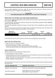
All <strong>RL</strong> series burners are fi tted with a new microprocessor control panel for the supervision during intermittent operation.For helping the commissioning and maintenance work, there are two main elements:The lock-out reset button is the central operatingelement for resetting the burner control and foractivating / deactivating the diagnostic functions.The multi-color LED is the central indication elementfor visual diagnosis and interface diagnosis.Both elements are located under the transparent cover of lockoutreset button, as showed below.There are two diagnostic choices, for indication of operation anddiagnosis of fault cause:VISUAL DIAGNOSISINTERFACE DIAGNOSISBy the interface adapter and a PC with dedicated software or bya predisposed fl ue gas analyzer (see paragraph accessories).INTERFACE ADAPTERCOMPUTERorFLUE GASANALYSERINDICATION OF OPERATIONIn normal operation, the various status are indicated in the form ofcolour codes according to the table below.The interface diagnosis (with adapter) can be activated by pressingthe lock-out button for > 3 seconds.COLOR CODE TABLEOperation statusStand-byPre-purgingIgnition phaseFlame OKPoor flameUndervoltage, built-in fuseFault, alarmExtraneous lightLED offColor code table9