RL Series - riello
RL Series - riello
RL Series - riello

Create successful ePaper yourself
Turn your PDF publications into a flip-book with our unique Google optimized e-Paper software.
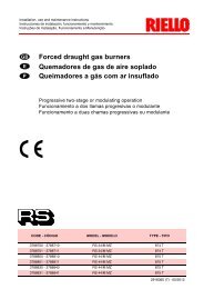
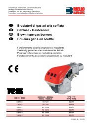
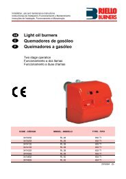
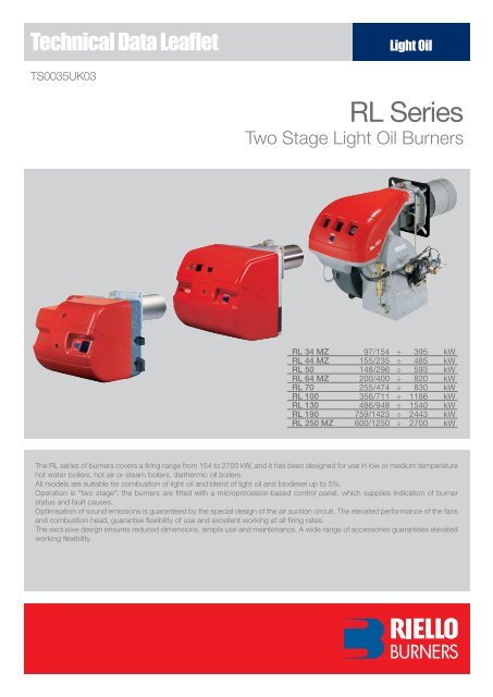
Technical Data LeafletTS0035UK03Light Oil<strong>RL</strong> <strong>Series</strong>Two Stage Light Oil Burners<strong>RL</strong> 34 MZ 97/154 ÷ 395 kW<strong>RL</strong> 44 MZ 155/235 ÷ 485 kW<strong>RL</strong> 50 148/296 ÷ 593 kW<strong>RL</strong> 64 MZ 200/400 ÷ 820 kW<strong>RL</strong> 70 255/474 ÷ 830 kW<strong>RL</strong> 100 356/711 ÷ 1186 kW<strong>RL</strong> 130 486/948 ÷ 1540 kW<strong>RL</strong> 190 759/1423 ÷ 2443 kW<strong>RL</strong> 250 MZ 600/1250 ÷ 2700 kWThe <strong>RL</strong> series of burners covers a fi ring range from 154 to 2700 kW, and it has been designed for use in low or medium temperaturehot water boilers, hot air or steam boilers, diathermic oil boilers.All models are suitable for combustion of light oil and blend of light oil and biodiesel up to 5%.Operation is “two stage”; the burners are fi tted with a microprocessor-based control panel, which supplies indication of burnerstatus and fault causes.Optimisation of sound emissions is guaranteed by the special design of the air suction circuit. The elevated performance of the fansand combustion head, guarantee fl exibility of use and excellent working at all fi ring rates.The exclusive design ensures reduced dimensions, simple use and maintenance. A wide range of accessories guarantees elevatedworking fl exibility.
Technical Data<strong>RL</strong> <strong>Series</strong>MODEL <strong>RL</strong> 34 MZ <strong>RL</strong> 44 MZ <strong>RL</strong> 50 <strong>RL</strong> 64 MZBurner operation modeTwo stageModulation ratio to max. output 2 ÷ 1Servomotortype --run time s --kW 97/154÷395 155/235÷485 148/296÷593 200/400÷820Heat outputMcal/h 83/133÷340 133/204÷418 127/255÷510 172/344÷705Kg/h 8,3/13÷33,6 13/20÷41 12,5/25÷50 17/38÷69Working temperature °C min./max . 0/40FUEL/AIR DATANet calorific valuekWh/kg 11,8Kcal/kg 10200Viscosity at 20°C mm 2 /s (cSt) 4 ÷ 6Pumptype AN 57C AN 67C AL 75C AL 95Coutput kg/h at 12 bar 45 67 88 107Atomised pressure bar 12Oil temperature Max. °C 50Fan type (02) (02) (01) (02)Air temperature Max. °C 60ELECTRICAL DATAElectrical supply Ph/Hz/V (04) (04) (06) (09) (05)Auxiliary electrical supply Ph/Hz/V (04) (04) (03) (03)Control box type RMO 88.53Total electrical power kW 0,6 0,7 0,75 0,75 1,4Auxiliary electrical power kW 0,3 0,28 0,3 0,10 0,3Protection level IP 2XD 2XD 44 44Power electric motor kW 0,3 0,42 0,45 0,65 1,1Rated motor current A 2,4 3 2 - 1.2 3 - 1,7 4.7 - 2.7Motor start current A 9,6 12 9.5 - 5.5 13,8 - 8 24.5 - 14Motor protection level IP 20 44 54 55Ignition transformerV1 - V2 230V - 2x12kV 230V - 2x12kV 230V - 2x5kV 230V - 2x5kVI1 - I2 0,2A - 30mA 0,2A - 30mA 1,9A - 30mA 1,9A - 30mAOperation (11) (11) (10) (11)EMISSIONSSound pressure dBA 70 72 75 76Sound output W --CO emission mg/kWh < 40Grade of smoke indicator N° Bach. < 1CxHy emission mg/kWh
MODEL <strong>RL</strong> 70 <strong>RL</strong> 100 <strong>RL</strong> 130 <strong>RL</strong> 190 <strong>RL</strong> 250 MZBurner operation modeTwo stageModulation ratio to max. output 2 ÷ 1Servomotortype -- LKS 210run time s -- 7kW 255/474÷830 356/711÷1186 486/948÷1540 759/1423÷2443 600/1250÷2700Heat outputMcal/h 219/408÷714 306/612÷1020 418/816÷1325 653/1224÷2100 516/1075÷2322Kg/h 21,5/40÷70 30/60÷100 41/80÷130 64/120÷206 51/106÷228Working temperature °C min./max . 0/40FUEL/AIR DATANet calorific valuekWh/kg 11,8Kcal/kg 10200Viscosity at 20°C mm 2 /s (cSt) 4 ÷ 6Pumptype AL 95C AJ 6CC AJ 6CC J7C J7 4PToutput kg/h at 12 bar 107 164 164 230 230Atomised pressure bar 12Oil temperature Max. °C 50Fan type (01) (01) (01) (02) (02)Air temperature Max. °C 60ELECTRICAL DATAElectrical supply Ph/Hz/V (09) (09) (09) (09) (07)Auxiliary electrical supply Ph/Hz/V (03) (03) (03) (03) (03)Control box type RMO 88.53Total electrical power kW 1,4 1,8 2,6 5,9 7,2Auxiliary electrical power kW 0,3 0,3 0,4 1,4 0,6Protection level IP 44 44 44 44 54Power electric motor kW 1,1 1,5 2,2 4,5 6,6Rated motor current A 4,8 - 2,8 5,9 - 3,4 8,8 - 5,1 15,8 - 9,1 14.8 - 8.5Motor start current A 25 - 14,6 27,7 - 16 57,2 - 33,2 126 - 73 114 - 66Motor protection level IP 54 54 54 54 55Ignition transformerV1 - V2 230V - 2x5kV 230V - 2x5kV 230V - 2x5kV 230V - 2x5kV 230V - 2x5kVI1 - I2 1,9A - 30mA 1,9A - 30mA 1,9A - 30mA 1,9A - 35mA 1,9A - 35mAOperation (10) (10) (10) (10) (11)EMISSIONSSound pressure dBA 75 77 78,5 83,9 83Sound output W --CO emission mg/kWh < 40Grade of smoke indicator N° Bach. < 1CxHy emission mg/kWh
<strong>RL</strong> <strong>Series</strong>FIRING RATESUseful working fieldfor choosing theburner1 st stage operatingrateTest conditionsconforming toEN 267:Temperature: 20°CPressure: 1013,5 mbarAltitude: 0 m a.s.l.4
Fuel SupplyHYDRAULIC CIRCUITSThe burners are fi tted with three valves (a safety valve and two oildelivery valves).A control device, on the basis of required output, regulates oildelivery valves opening, allowing light oil passage trough thevalves and the nozzle.Delivery valves opening supplies the two-stage hydraulic ramwhich regulates air delivery in relation to the fuel burnt.The pumping group is fitted whit a pump, an oil filter and aregulating valve, that adjust atomised pressure.Example of adjustable hydraulic ram of <strong>RL</strong> 34 - 44 MZ burners.<strong>RL</strong> 34 MZ<strong>RL</strong> 44 MZ - 50 - 64 MZVF2VF1U1U2VSVF2VF1U1U2VCVCPPADADMTMT<strong>RL</strong> 70 - 100 - 130<strong>RL</strong> 190VF2VF1VF2VF1VSU1U2VSU1U2VCPPADADMTMT<strong>RL</strong> 250 MZPVSVF1VF2MSMADU2U1PVSVF1VF2VCMTADU1U2Pump with fi lter and pressure regulator on the outputcircuitSafety valve on the output circuit1 st stage valve2 nd stage valve2 nd stage control deviceHydraulic ramAir damper1 st stage nozzle2 nd stage nozzle5
Combustion Head<strong>RL</strong> <strong>Series</strong>Different lengths of the combustion head can be chosen for the<strong>RL</strong> series of burners.The choice depends on the thickness of the front panel and thetype of boiler.Depending on the type of generator, check that the penetration ofthe head into the combustion chamber is correct.The internal position of the combustion head can easily beadjusted to the maximum defi ned output by adjusting a screwfi xed to the fl ange.Example of a <strong>RL</strong> burner combustion head.DIMENSIONS OF THE FLAMEExample:Burner thermal output = 2000 kW;L fl ame (m) = 2,7 m (medium value);D fl ame (m) = 0,8 m (medium value)Lenght of the flame (m)L maxL minD maxD minDiameter of the flame (m)Burner output (MW)OperationBURNER OPERATION MODEWith two stage operation, the <strong>RL</strong> burners can follow thetemperature load requested by the system.A modulation ratio of 2:1 is reached, thanks to the “two nozzles”technique; the air is adapted to the hydraulic ram positions.On “two stage” operation, the burner gradually adjusts output tothe requested level, by varying between the two pre-set levels(see picture A).“TWO STAGE” OPERATIONPicture A8
All <strong>RL</strong> series burners are fi tted with a new microprocessor control panel for the supervision during intermittent operation.For helping the commissioning and maintenance work, there are two main elements:The lock-out reset button is the central operatingelement for resetting the burner control and foractivating / deactivating the diagnostic functions.The multi-color LED is the central indication elementfor visual diagnosis and interface diagnosis.Both elements are located under the transparent cover of lockoutreset button, as showed below.There are two diagnostic choices, for indication of operation anddiagnosis of fault cause:VISUAL DIAGNOSISINTERFACE DIAGNOSISBy the interface adapter and a PC with dedicated software or bya predisposed fl ue gas analyzer (see paragraph accessories).INTERFACE ADAPTERCOMPUTERorFLUE GASANALYSERINDICATION OF OPERATIONIn normal operation, the various status are indicated in the form ofcolour codes according to the table below.The interface diagnosis (with adapter) can be activated by pressingthe lock-out button for > 3 seconds.COLOR CODE TABLEOperation statusStand-byPre-purgingIgnition phaseFlame OKPoor flameUndervoltage, built-in fuseFault, alarmExtraneous lightLED offColor code table9
<strong>RL</strong> <strong>Series</strong>DIAGNOSIS OF FAULT CAUSESAfter lock-out has occurred, the red signal lamp is steady on. In this status, the visual fault diagnosis according to the error code table canbe activated by pressing the lock-out reset button for > 3 seconds.The interface diagnosis (with adapter) can be activated by pressing again the lock-out button for > 3 seconds.The fl ashing of red LED are a signal with this sequence :(e.g. signal with n° 3 fl ashes – faulty air pressure monitor)3s 3s 3s( LED off)ERROR CODE TABLEPOSSIBLE CAUSE OF FAULTNo establishment of flame at the end of safety time:- faulty or soiled fuel valves- faulty or soiled fl ame detector- poor adjustment of burner, no fuel- faulty ignition equipmentFLASH CODE2x fl ashesFaulty air pressure monitor 3x fl ashesExtraneous light or simulation of flame on burner start up 4x fl ashesLoss of flame during operation:- faulty or soiled fuel valves- faulty or soiled fl ame detector- poor adjustment of burner7x fl ashesWiring error or internal fault 10x fl ashesSTART UP CYCLE<strong>RL</strong> 34 MZ - 44 MZ - 50 - 64 MZ - 70 - 100 - 130 - 190 - 250 MZMVF1VF2TLTR32222936A0 s The burner begins the fi ring cycle: the motor andtransformer are supplied; the hydraulic ram opens inthe pre-purge position.22÷29 s Ignition: the VS and VF1 valves are supplied.36 s If the control device TR is closed or has been replacedby a jumper wire, the 2 nd stage valve VF2 opens; thefuel is sprayed out through the 2 nd stage nozzle andthe hydraulic ram opens the air damper in the 2 nd stageposition.2°1°022°1°0ARMOLED0Off Yellow Greentime (s)10
Burner WiringAll models of the <strong>RL</strong> burner series have an easily accessible control panel for the electrical components housing and wiring.In particular the new <strong>RL</strong> 34-44 MZ models, thanks to the new structure concept, have a extremely clean electrical layout to optimise thecommissioning and maintenance speed.On these models the electrical connection are done by a Plug&Socket system, accessible from the external of the cover.The electrical wiring of all <strong>RL</strong> burner models are very easy to do following the wiring diagrams included in the instruction handbook.Electrical connections must be made by qualifi ed and skilled personnel, according to the local norms.Example of electrical components housing and Plug&Socket system for electrical connection of <strong>RL</strong> 34 - 44 MZ.The following table shows the supply lead sections and the type of fuse to be used.MODEL V F (A) L (mm 2 )u <strong>RL</strong> 34 MZ 230 T6 1,5u <strong>RL</strong> 44 MZ 230 T6 1,5u <strong>RL</strong> 44 MZ230 T6 1,5400 T6 1,5u <strong>RL</strong> 50230 T6 1,5400 T6 1,5u <strong>RL</strong> 64 MZ230 T10 1,5400 T6 1,5u <strong>RL</strong> 70230 T10 1,5400 T6 1,5MODEL V F (A) L (mm 2 )u <strong>RL</strong> 100230 T16 1,5400 T10 1,5u <strong>RL</strong> 130230 T16 1,5400 T10 1,5u <strong>RL</strong> 190230 T25 2,5400 T25 2,5u <strong>RL</strong> 250 MZ 400 16A aM - 32A gG 4V = Electrical supply F = Fuse L = Lead section11
Emissions<strong>RL</strong> <strong>Series</strong>The emission data has been measured in the various models at maximum output, according to EN 267 standard.The NOx emissions of <strong>RL</strong> 34-44-64-250 MZ models are conforming to the class 2 of EN 267.mg/kWh250200NO 2Emissions150100500mg/kWh504030CO Emissions20100dB(A)10080Noise Emissions604020012
Overall Dimensions (mm)BURNERS<strong>RL</strong> 34 - 44 MZ <strong>RL</strong> 50MODEL A D E F - F(1) H I L O - O(1)u <strong>RL</strong> 34 MZ 442 422 508 216 - 351 140 305 138 780 - 915u <strong>RL</strong> 44 MZ 442 422 508 216 - 351 152 305 138 780 - 915u <strong>RL</strong> 50 476 474 468 216 - 351 152 352 52 672 - 807(1) dimension with extended head<strong>RL</strong> 64 MZ<strong>RL</strong> 70 - 100 - 130 - 190 - 250 MZ MODEL A B C D E F - F(1) H I L O - O(1)u <strong>RL</strong> 64 MZ 538 300 238 490 477 250 - 385 179 335 60 680 - 545u <strong>RL</strong> 70 580 296 284 555 680 250 - 385 179 430 - 951 - 1086u <strong>RL</strong> 100 599 312 287 555 680 250 - 385 179 430 - 951 - 1086u <strong>RL</strong> 130 625 338 287 555 680 250 - 385 189 430 - 951 - 1086u <strong>RL</strong> 190 756 366 390 555 712 370 - - 222 430 - 1166 - -u <strong>RL</strong> 250 MZ 910 432 478 596 705 378 - - 222 436 - 1163 - -(1) dimension with extended head13
<strong>RL</strong> <strong>Series</strong>BURNER - BOILER MOUNTING FLANGEMODEL D1 D2 Øu <strong>RL</strong> 34 MZ 160 224 M8u <strong>RL</strong> 44 MZ 160 224 M8u <strong>RL</strong> 50 160 224 M8u <strong>RL</strong> 64 MZ 185 275-325 M12u <strong>RL</strong> 70 185 275-325 M12u <strong>RL</strong> 100 185 275-325 M12u <strong>RL</strong> 130 195 275-325 M12u <strong>RL</strong> 190 230 325-368 M16u <strong>RL</strong> 250 MZ 230 325-368 M16PACKAGINGMODEL X (1) Y Z kgZX (1)Yu <strong>RL</strong> 34 MZ 1010 520 510 32u <strong>RL</strong> 44 MZ 1010 520 510 33u <strong>RL</strong> 50 1200 520 502 39u <strong>RL</strong> 64 MZ 1200 560 520 42u <strong>RL</strong> 70 1410 692 655 60u <strong>RL</strong> 100 1410 692 655 63u <strong>RL</strong> 130 1410 692 655 66u <strong>RL</strong> 190 1410 985 655 75u <strong>RL</strong> 250 MZ 1410 1040 655 140(1) Length with short and extended head14
Installation DescriptionInstallation, start up and maintenance must be carried out by qualifi ed and skilled personnel.All operations must be performed in accordance with the technical handbook supplied with the burner.BURNER SETTINGAll the burners have slide bars, for easier installation and maintenance.After drilling the boilerplate, using the supplied gasket as a template, dismantle the blasttube from the burner and fi x it to the boiler.Adjust the combustion head.Refi t the burner casing to the slide bars.Install the nozzle, choosing this on the basis of the maximum boiler output and followingthe diagrams included in the burner instruction handbook.Check the position of the electrodes.Close the burner, sliding it up to the fl ange, keeping it slightly raised to avoid the fl amestability disk rubbing against the blast tube.HYDRAULIC AND ELECTRICAL CONNECTIONS AND START UPThe burners are supplied for connection to two pipes fuel supply system.Connect the ends of the fl exible pipes to the suction and return pipework using thesupplied nipples.Make the electrical connections to the burner following the wiring diagrams included in theinstruction handbook.Prime the pump by turning the motor.On start up, check:- Pressure pump (to max. and min.)- Combustion quality, in terms of unburned substances and excess air.BURNER MAINTENANCEThe maintenance of <strong>RL</strong> burners is very simple thanks to the sliding bars system that allowsan easy access to the internal components.In particular the <strong>RL</strong> 34-44 MZ models have a new sliding bars system to make easier theaccess to the combustion head.The <strong>RL</strong> 190 and <strong>RL</strong> 250 MZ have new reinforced sliding bars that make very strong theburner structure during maintenance.15
<strong>RL</strong> <strong>Series</strong>Burner AccessoriesNozzles type 60° BThe nozzles must be ordered separately. The following table shows the features and codes onthe basis of the maximum required fuel output.BURNER GPH RATED OUTPUT (kg/h)at 10 bar at 12 bar at 14 barNOZZLECODEu <strong>RL</strong> 34 MZ 1,00 4,1 4,5 4,9 3042077u <strong>RL</strong> 34 MZ 1,25 4,7 5,2 5,6 3042096u <strong>RL</strong> 34 - 44 MZ 1,50 5,7 6,3 6,8 3042107u <strong>RL</strong> 34 - 44 MZ 1,75 6,7 7,3 7,9 3042110u <strong>RL</strong> 34 MZ - 44 MZ 2,00 7,7 8,5 9,2 3042126u <strong>RL</strong> 34 MZ - 44 MZ 2,50 9,6 10,6 11,5 3042140u <strong>RL</strong> 34 MZ - 44 MZ - 50 3,00 11,5 12,7 13,8 3042158u <strong>RL</strong> 34 MZ - 44 MZ - 50 3,50 13,5 14,8 16,1 3042162u <strong>RL</strong> 34 MZ - 44 MZ - 50 - 64 MZ 4,00 15,4 17 18,4 3042172u <strong>RL</strong> 34 MZ - 44 MZ - 50 - 64 MZ 4,50 17,3 19,1 20,7 3042182u <strong>RL</strong> 44 MZ - 50 - 64 MZ - 70 5,00 19,2 21,2 23 3042192u <strong>RL</strong> 44 MZ - 50 - 64 MZ - 70 5,50 21,1 23,3 25,3 3042202u <strong>RL</strong> 44 MZ - 50 - 64 MZ - 70 6,00 23,1 25,5 27,7 3042212u <strong>RL</strong> 50 - 64 MZ - 70 6,50 25 27,6 30 3042222u <strong>RL</strong> 64 MZ - 70 - 100 7,00 26,9 29,7 32,3 3042232u <strong>RL</strong> 64 MZ - 70 - 100 7,50 28,8 31,8 34,6 3042242u <strong>RL</strong> 64 MZ - 70 - 100 8,00 30,8 33,9 36,9 3042252u <strong>RL</strong> 64 MZ - 70 - 100 8,50 32,7 36,1 39,2 3042262u <strong>RL</strong> 64 MZ - 70 - 100 - 130 9,50 36,5 40,3 43,8 3042282u <strong>RL</strong> 64 MZ - 70 - 100 - 130 - 190 10,00 38,4 42,4 46,1 3042292u <strong>RL</strong> 64 MZ - 70 - 100 - 130 - 190 11,00 42,3 46,7 50,7 3042312u <strong>RL</strong> 64 MZ - 100 - 130 - 190 - 250 MZ 12,00 46,1 50,9 55,3 3042322u <strong>RL</strong> 64 MZ - 100 - 130 - 190 - 250 MZ 13,00 50 55,1 59,9 3042332u <strong>RL</strong> 64 MZ - 100 - 130 - 190 - 250 MZ 14,00 53,8 59,4 64,5 3042352u <strong>RL</strong> 64 MZ - 100 - 130 - 190 - 250 MZ 15,00 57,7 63,6 69,2 3042362u <strong>RL</strong> 64 MZ - 100 - 130 - 190 - 250 MZ 16,00 61,5 67,9 73,8 3042382u <strong>RL</strong> 64 MZ - 130 - 190 - 250 MZ 17,00 65,4 72,1 78,4 3042392u <strong>RL</strong> 130 - 190 - 250 MZ 18,00 69,2 76,4 83 3042412u <strong>RL</strong> 130 - 190 - 250 MZ 19,00 73 80,6 87,6 3042422u <strong>RL</strong> 130 - 190 - 250 MZ 20,00 76,9 84,8 92,2 3042442u <strong>RL</strong> 190 - 250 MZ 22,00 84,6 93,3 101,4 3042462u <strong>RL</strong> 190 - 250 MZ 24,00 92,2 101,8 110,6 3042472u <strong>RL</strong> 190 - 250 MZ 26,00 99,9 110,3 119,9 3042482u <strong>RL</strong> 190 - 250 MZ 28,00 107,6 118,8 129,1 3042492u <strong>RL</strong> 250 MZ 30,00 110,4 122 132,4 3042502u <strong>RL</strong> 250 MZ 32,00 117,8 130,1 150,1 3042512u <strong>RL</strong> 250 MZ 35,00 128,8 142,1 154,5 304252216
Extended heads“Standard head” burners can be transformed into “extended head” versions, by using the specialkit. The kits available for the various burners, giving the original and the extended lengths, arelisted below.BURNER‘STANDARD’HEAD LENGTH (mm)‘EXTENDED’HEAD LENGTH (mm)KITCODEu <strong>RL</strong> 34 MZ 216 351 3010426u <strong>RL</strong> 44 MZ 216 351 3010425u <strong>RL</strong> 50 216 351 3010075u <strong>RL</strong> 64 MZ 250 385 3010114u <strong>RL</strong> 70 250 385 3010114u <strong>RL</strong> 100 250 385 3010115u <strong>RL</strong> 130 250 385 3010116u <strong>RL</strong> 190 370 530 3010444u <strong>RL</strong> 250 MZ 378 528 3010422Spacer kitIf burner head penetration into the combustion chamber needs reducing, varying thicknessspacers are available, as given in the following table:BURNERSPACER THICKNESS S(mm)KITCODEu <strong>RL</strong> 34 MZ - 44 MZ - 50 90 3010095u <strong>RL</strong> 64 MZ - 70 - 100 - 130 135 3010129u <strong>RL</strong> 190 - 250 MZ 110 3000722Sound proofing boxIf noise emission needs reducing even further, sound-proofi ng boxes are available, as given inthe following table:BURNERBOXTYPEAVERAGE NOISEREDUCTION [dB(A)](*)BOXCODEu <strong>RL</strong> 34 MZ - 44 MZ - 50 - 70 - 100 - 130 C1/3 10 3010403u <strong>RL</strong> 64 MZ - 190 C4/5 10 3010404u <strong>RL</strong> 250 MZ C7 10 3010376(*) according to EN 15036-1 standardConnection flange kitA kit is available for use where the burner opening on the boiler is of excessive diameter.BURNERKIT CODEu <strong>RL</strong> 34 MZ - 44 MZ - 50 301013817
<strong>RL</strong> <strong>Series</strong>Degasing unitWith single pipe systems, you can fi nd air in the oil sucked by the pump that comes from the oilitself due to negative pressure or to a faulty seal.To solve this problem, we recommend fi tting a degasing unit near the burner. Two versions areavailable with or without fi lter:BURNERDEGASING UNITWITH FILTER CODEDEGASING UNITWITHOUT FILTER CODE<strong>RL</strong> 34 MZ - 44 MZ - 50 - 64 MZu<strong>RL</strong> 70 - 100 - 130 - 190 - 250 MZ3010055 3010054Biodiesel kitFor burning Biodiesel fuel, a special kit is available.BURNERKIT CODEStatus Panel kitu <strong>RL</strong> 28 (out of catalogue model) 3010289u <strong>RL</strong> 38 (out of catalogue model) 3010290u <strong>RL</strong> 50 3010291u <strong>RL</strong> 70 3010292u <strong>RL</strong> 100 3010358u <strong>RL</strong> 130 3010358u <strong>RL</strong> 190 -The <strong>RL</strong> burners can be equipped with an exclusive electronic device “Status Panel” whichcontinuously monitors and displays all the burner operational modes and picks up any anomaliesduring the operational cycle.BURNERKIT CODEu <strong>RL</strong> 50 - 64 MZ - 70 - 100 - 130 - 190 - 250 MZ 3010322Volt free contact kitA volt free contact kit is available for installation onto the burner. It can be used for a remoteinterface between burner operating signals.Every burner can be equipped with a single kit to remote the fl ame presence signal or the burnerlockout indication.BURNERKIT CODEu <strong>RL</strong> 34 MZ - 44 MZ - 64 MZ 3010419PC interface kitTo connect the fl ame control panel to a personal computer for the transmission of operation, faultsignals and detailed service information, an interface adapter with PC software are available.BURNERKIT CODEu <strong>RL</strong> 34 MZ - 44 MZ - 50 - 64 MZ - 70 - 100 - 130 - 190 - 250 MZ 300271918
Ground fault interrupter kitA “Ground fault interrupter kit” is available as a safety device for electrical system fault.BURNERKIT CODEu <strong>RL</strong> 34 MZ - 44 MZ 3010448Post-ventilation kitTo have 20 s ventilation after opening of thermostats chain, a special kit is available.BURNERKIT CODEu <strong>RL</strong> 34 MZ - 44 MZ 3010453Hours counter kitTo measure the burner working time a hours counter kit is available.BURNERKIT CODEu <strong>RL</strong> 34 MZ - 44 MZ 301045019
Specification<strong>RL</strong> <strong>Series</strong>DESIGNATION OF SERIESA specifi c index guides your choice of burner from the various models available in the <strong>RL</strong> series.Below is a clear and detailed specifi cation description of the product.<strong>Series</strong>: RFuel: S Natural GasSP LPGL Light oilLS Light oil/MethaneN Heavy oilSizeSetting: /1 Single stage... Two stage/M ModulatingEmission: ... Class 1 EN267 - EN676MZ Class 2 EN267 - EN676BLU Class 3 EN267 - EN676MXClass 1 EN267Class 3 EN676Head length: TC standard headTL extended headFlame control system:FS1 Standard (1 stop every 24 h)FS2 Continuous working (1 stop every 72 h)Electrical supply to the system:1/230/50 1/230V/50Hz1/220-230/50-60 1/220-230V/50-60Hz3/230/50 3/230V/50Hz3/400/50 3N/400V/50Hz3/230-400/50 3/230V/50Hz - 3N/400V/50Hz3/220/60 3/220V/60Hz3/380/60 3N/380V/60Hz3/220-380/60 3/220V/60Hz - 3N/380V/60Hz3/220-400/50-603/220-230V/50-60Hz3/380-400V/50-60HzAuxiliary voltage:230/50-60 230V/50-60Hz220-230/50-60 220-230V/50-60Hz110/50-60 110V/50-60HzID:Differential switchR L 50 TC FS1 3/230-400/50 230/50-60BASIC DESIGNATIONEXTENDED DESIGNATION20
AVAILABLE BURNER MODELS<strong>RL</strong> 34 MZ TC FS1 1/220-230/50/60 220-230/50-60<strong>RL</strong> 34 MZ TL FS1 1/220-230/50/60 220-230/50-60<strong>RL</strong> 44 MZ TC FS1 1/220-230/50/60 220-230/50-60<strong>RL</strong> 44 MZ TL FS1 1/220-230/50/60 220-230/50-60<strong>RL</strong> 44 MZ TC FS1 3/220-400/50/60 220-230/50-60<strong>RL</strong> 44 MZ TL FS1 3/220-400/50/60 220-230/50-60<strong>RL</strong> 50 TC FS1 3/230-400/50 230/50-60<strong>RL</strong> 50 TL FS1 3/230-400/50 230/50-60<strong>RL</strong> 50 TC FS1 3/230-400/50 230/50-60<strong>RL</strong> 50 TL FS1 3/230-400/50 230/50-60<strong>RL</strong> 50 TC FS1 3/220-230/380-400/60 230/50-60<strong>RL</strong> 50 TL FS1 3/220-230/380-400/60 230/50-60<strong>RL</strong> 50 TC FS1 3/254-265/440-460/60 230/50-60<strong>RL</strong> 50 TL FS1 3/254-265/440-460/60 230/50-60<strong>RL</strong> 64 MZ TC FS1 3/230-400/50 230/50-60<strong>RL</strong> 64 MZ TL FS1 3/230-400/50 230/50-60<strong>RL</strong> 70 TC FS1 3/230-400/50 230/50-60<strong>RL</strong> 70 TL FS1 3/230-400/50 230/50-60<strong>RL</strong> 70 TC FS1 3/230-400/50 230/50-60<strong>RL</strong> 70 TL FS1 3/230-400/50 230/50-60<strong>RL</strong> 70 TC FS1 3/220-230/380-400/60 230/50-60<strong>RL</strong> 70 TL FS1 3/220-230/380-400/60 230/50-60<strong>RL</strong> 70 TC FS1 3/254-265/440-460/60 230/50-60<strong>RL</strong> 70 TL FS1 3/254-265/440-460/60 230/50-60<strong>RL</strong> 100 TC FS1 3/230-400/50 230/50-60<strong>RL</strong> 100 TL FS1 3/230-400/50 230/50-60<strong>RL</strong> 100 TC FS1 3/230-400/50 230/50-60<strong>RL</strong> 100 TL FS1 3/230-400/50 230/50-60<strong>RL</strong> 100 TC FS1 3/220-230/380-400/60 230/50-60<strong>RL</strong> 100 TL FS1 3/220-230/380-400/60 230/50-60<strong>RL</strong> 100 TC FS1 3/254-265/440-460/60 230/50-60<strong>RL</strong> 100 TL FS1 3/254-265/440-460/60 230/50-60<strong>RL</strong> 130 TC FS1 3/230-400/50 230/50-60<strong>RL</strong> 130 TL FS1 3/230-400/50 230/50-60<strong>RL</strong> 130 TC FS1 3/230-400/50 230/50-60<strong>RL</strong> 130 TL FS1 3/230-400/50 230/50-60<strong>RL</strong> 130 TC FS1 3/220-230/380-400/60 230/50-60<strong>RL</strong> 130 TL FS1 3/220-230/380-400/60 230/50-60<strong>RL</strong> 130 TC FS1 3/254-265/440-460/60 230/50-60<strong>RL</strong> 130 TL FS1 3/254-265/440-460/60 230/50-60<strong>RL</strong> 190 TC FS1 3/230-400/50 230/50-60<strong>RL</strong> 190 TC FS1 3/220-230/380-400/60 230/50-60<strong>RL</strong> 190 TC FS1 3/254-265/440-460/60 230/50-60<strong>RL</strong> 250 MZ TC FS1 3/400/50 230/50-60Other versions are available on request.21
<strong>RL</strong> <strong>Series</strong>PRODUCT SPECIFICATION<strong>RL</strong> 34 MZ - 44 MZ modelsBurnerMonoblock forced draught oil burner (light oil or blend of light oil and biodiesel up to 5%) with two stage operation, fully automatic, made up of:- Air suction circuit- High performance fan with straight blades- Air damper for air setting controlled by an adjustable hydraulic ram- Starting motor at 2800 rpm, single-phase / 220-230V / 50-60Hz or three-phase 380-400V / 50-60Hz- Combustion head, that can be set on the basis of required output, fi tted with:- stainless steel end cone, resistant to corrosion and high temperatures- ignition electrodes- fl ame stability disk- Exclusive patented HCS (Housing Cooling System) with high thermal insulation and air circulation with continuous air volume refresh for anactive cooling system and avoid heat transfer to the electrical component housing- Gears pump for high pressure fuel supply, fi tted with:- fi lter- pressure regulator- connections for installing a pressure gauge and vacuometer- internal by-pass for single pipe installation- Valve unit with an oil safety valve and two delivery oil valves on the output circuit- Photocell for fl ame detection- Microprocessor-based fl ame control panel, with diagnostic function- Plugs and Sockets for electrical connection, accessible from the external of the cover- Burner on/off switch- Flame inspection window- 1 st - 2 nd stage manual switch- Slide bars for easier installation and maintenance- Protection fi lter against radio interference- IP 44 electric protection level.Conforming to:- 89/336 (2004/108) EC directive (electromagnetic compatibility)- 73/23 (2006/95) EC directive (low voltage)- 92/42/EC directive (performance)- 98/37/EC directive (machinery)- EN 267 (liquid fuel burners).Standard equipment:- 2 fl exible pipes for connection to the oil supply network- 2 gaskets for the fl exible pipes- 2 nipples for connection to the pump- 4 screws for fi xing the burner fl ange to the boiler- 1 thermal screen- 2 Plugs for electrical connection (<strong>RL</strong> 34-44 MZ single-phase)- 3 Plugs for electrical connection (<strong>RL</strong> 44 MZ three-phase)- 2 slide bar extensions (for the extended head models)- Instruction handbook for installation, use and maintenance- Spare parts catalogue.Available accessories to be ordered separately:- Nozzles- Head extension kit- Head length reduction kit- Sound-proofi ng box- Connection fl ange kit- Degasing unit (with or without fi lter)- Biodiesel kit- Status panel kit- Volt free contact kit- PC interface kit- Ground fault interrupter- Post-ventilation kit- Hours counter kit.22
<strong>RL</strong> 50 - 64 MZ - 70 - 100 - 130 - 190 - 250 MZ modelsBurnerMonoblock forced draught oil burner (light oil or blend of light oil and biodiesel up to 5%) with two stage operation, fully automatic, made up of:- Air suction circuit lined with sound-proofi ng material- Fan with reverse curve blades (<strong>RL</strong> 50 - 70 - 100 - 130 models) or straight blades (<strong>RL</strong> 64 MZ - 190 - 250 MZ models)- Air damper for air setting controlled by an adjustable hydraulic ram (or by a servomotor for the <strong>RL</strong> 250 MZ)- Starting motor at 2800 rpm, three-phase 400V with neutral, 50Hz- Combustion head, that can be set on the basis of required output, fi tted with:- stainless steel end cone, resistant to corrosion and high temperatures- ignition electrodes- fl ame stability disk- Gears pump for high pressure fuel supply, fi tted with:- fi lter- pressure regulator- connections for installing a pressure gauge and vacuometer- internal by-pass for single pipe installation- Valve unit with an oil safety valve and two delivery oil valves on the output circuit- Photocell for fl ame detection- Microprocessor-based fl ame control panel, with diagnostic function- Burner on/off switch- Flame inspection window- 1 st - 2 nd stage manual switch- Slide bars for easier installation and maintenance- Protection fi lter against radio interference- IP 44 electric protection level.Conforming to:- 89/336 (2004/108) EC directive (electromagnetic compatibility)- 73/23 (2006/95) EC directive (low voltage)- 92/42/EC directive (performance)- 98/37/EC directive (machinery)- EN 267 (liquid fuel burners).Standard equipment:- 2 fl exible pipes for connection to the oil supply network- 2 gaskets for the fl exible pipes- 2 nipples for connection to the pump- 4 screws for fi xing the burner fl ange to the boiler- 1 thermal screen- Fairleads for electrical connections (<strong>RL</strong> 50 models)- 2 slide bar extensions (for the extended head models and the <strong>RL</strong> 190 - 250 MZ models)- Instruction handbook for installation, use and maintenance- Spare parts catalogue.Available accessories to be ordered separately:- Nozzles- Head extension kit- Head length reduction kit- Sound-proofi ng box- Degasing unit (with or without fi lter)- Biodiesel kit- Connection fl ange kit- Status panel kit- PC interface kit.23
TS0035UK03 - 1/2008RIELLO S.p.A.Via Ing. Pilade Riello, 537045 Legnago (VR) ItalyTel. +39.0442.630111 - Fax +39.0442.21980www.<strong>riello</strong>burners.com - info@<strong>riello</strong>burners.comSince the Company is constantly engaged in the production improvement, the aesthetic and dimensionalfeatures, the technical data, the equipment and the accessories can be changed.This document contains confi dential and proprietary information of RIELLO S.p.A. Unless authorised, thisinformation shall not be divulged, nor duplicated in whole or in part.Riello Burners is a brand of Riello Group.