NEUTRALIZATION PROCESS OF ACID WELLS ... - Orkustofnun
NEUTRALIZATION PROCESS OF ACID WELLS ... - Orkustofnun
NEUTRALIZATION PROCESS OF ACID WELLS ... - Orkustofnun

You also want an ePaper? Increase the reach of your titles
YUMPU automatically turns print PDFs into web optimized ePapers that Google loves.
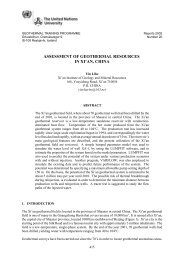
Report 16 373 Nietzen S.sampling and measurements in order to find which one gives the best measurements (is mostrepresentative for the situation in the well). For that aim, it was necessary to:• Analyse some plugs that formed in the capillary tube during sampling;• Analyse and make plots of amorphous silica saturation curves, and estimate the temperature ofsilica scaling with the chemical characteristics of each well with the aid of geochemicalreactions programs;• Do pH measurements on site as well as measure the head pressure from equipment installed inthe wells; discuss possible variations between readings and evaluate the feasibility of locations.The general description of the neutralization process is treated in Section 2 of this work. Section 3covers the design analysis (descriptions, results and discussions) and the conclusions are located inSection 4.2. GENERAL DESCRIPTION <strong>OF</strong> THE <strong>NEUTRALIZATION</strong> <strong>PROCESS</strong>2.1 Geochemical and thermohydraulic characterization of acid wellsThe Miravalles geothermal field has 3 mains aquifers (Rodríguez, 2006). These aquifers are shown inFigure 2 and are described briefly here below:Neutral sodium-chloride aquifer (Na-Cl): Its fluids have a sodium-chloride composition. It is locatedat the northern and central sectors. There is calcium carbonate scaling with chemical treatmentrequired to control it.FIGURE 2: Different zones of the Miravalles geothermal field. There are three mains aquifers:Na-Cl, Na-Cl-HCO 3 and Na-Cl-SO 4 ; the acid wells are locatedin the Na-Cl-SO 4 aquifer, indicated in dark grey / red
Nietzen S. 374 Report 16Neutral sodium-chloride-bicarbonate aquifer (Na-Cl-HCO3): Its fluids have a sodium-chloridebicarbonate composition. It is located in the southeast sector. There is severe calcium carbonatescaling with chemical treatment necessary to avoid it.Acid sodium-chloride-sulphate aquifer (Na-Cl-SO4): Its fluids have a sodium-chloride sulphatecomposition. It is located in the northeast sector. It has a low pH (2.4-3.2). Chemical treatment isnecessary to avoid corrosion in the well casings and surface equipment.Four acid wells with their respective neutralization systems are located in the acid sodium-chloridesulphateaquifer (Na-Cl-SO 4 ). These wells are PGM-02, PGM-06, PGM-07 and PGM-19. All ofthem have a low pH value and some similar characteristics. However, there are other productionzones competing inside each one. Some zones contribute more than others, and this behaviourchanges with time. These effects are responsible for the differences between the wells. Table 2 showsthe chemical compositions of the acid wells (average values). In summary, these four wells arelocated in the same area that gives them the acid characteristics, but each well has its own chemicaland thermohydraulic behaviour.TABLE 2: Chemical compositions of the fluids of the four acid wellsduring pH neutralization (average values)PGM-02(Oct06 to Agu07)PGM-06(2007)PGM-07(Oct06 to Sep07)PGM-19(Nov06 to Agu07)StandardStandardStandardStandardAverage deviation(±)Average deviation(±)Average deviation(±)Average deviation(±)Sep. pressure (bar-a.) 0.94 0.00 11 6 0.94 0.00 0.94 0.00pH* 5 1 5.17 0.74 5.7 0.5 5 1Conductivity (µS/cm) 12494 716 12629 878 13590 185 13303 265Na* (ppm) 2492 87 2417 221 2616 38 2522 69K (ppm) 310 8 312 22 328 11 316 3Ca (ppm) 40 1 34 5 47 3 47 4Mg (ppm) 7.8 0.6 4 2 2.2 0.4 3.9 0.6Fe total. (ppm) 4 6 1 2 1 1 1.5 0.4Cl (ppm) 4008 85 3689 340 4244 67 4140 35SO 4 (ppm) 305 32 536 68 168 23 166 44HCO 3 (ppm) 0.8 0.1 4 4 1.4 0.4 3 3F (ppm) 2.6 0.2 3.5 0.4 2.0 0.2 2.1 0.5B (ppm) 67 2 94 5 71 2 67 2H 2 S (ppm) 2.0 0.5 4 1 2 1 1 0NH 3 (ppm) 15 2 29 7 10 3 14 4As (ppm) 10.3 0.3 10 3 10.5 0.7 10 1SiO 2 total (ppm) 618 20 624 28 674 18 538 34SiO 2 mon.(ppm) 601 13 615 12 651 17 520 22TDS (ppm) 8118 175 8142 593 8282 354 8098 98Ionic balance 0 1 0.1 0.6 0.8 0.8 0.1 0.7CO 2 (mmoles/kg) 243 29 716 130 477 73 141 78H 2 S (mmoles/kg) 3.0 0.5 14 2 7 2 1.4 0.6N 2 (mmoles/kg) 1.4 0.4 2.2 0.5 1.6 0.2 1.1 0.5H 2 (mmoles/kg) 0.21 0.07 0.3 0.3 0.51 0.05 0.11 0.03Total 248 30 733 132 486 75 144 79% of vapour 1.1 0.1 3.2 0.6 2.1 0.3 0.6 0.3T Na/K (°C) 237 2 240 3 237 3 237 2T Na/K/Ca (°C) 242 1 246 1 242 2 240.9 0.7T quartz (°C) 239 2 241 1 245 2 231 5Enthalpy (kJ/kg) 1068 0 1700 0 1434 0 989 0* affected by the neutralization process
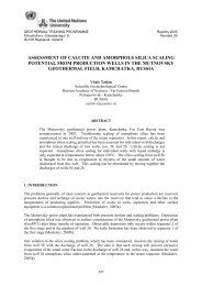
Report 16 375 Nietzen S.2.2 Philosophy of the neutralizationThe four acid wells in Miravalles are all producing energy for the power plants, and are located in thesame zone. The fluids from these wells are highly corrosive unless previously treated. The materialsin contact with the fluids (pipes, casing, capillary tube, separators, others) must be protected. The aimof a neutralization system is to protect all surface equipment from corrosion. A neutralizing fluid (likeNaOH) is injected into the well at ~1000 m depth, close to the main production zone by means of acapillary tube and a pump. Neutralizing liquid is stored in tanks. Figure 3 shows the overall diagramof the neutralization system applied in PGM-19 and in most of the wells. Some elements of thesystem are detailed.FIGURE 3: Fluid neutralization system in well PGM-19. The process begins in the tanks wherethe NaOH is stored (NaOH 1 and NaOH 2 in the diagram). The NaOH is transported through alow-pressure pipe to the pumps (“dosing pump”). Next, the NaOH is injected into a highpressurepipe, which ends at the beginning of the capillary tube (located in the spool). Thecapillary tube transports the NaOH to the well and keeps its position thanks to the injection head.The dotted line represents electric signs (from equipment to the display) and the continuous linerepresents the route of the soda. Each part of the diagram is explained in Section 22.2.1 NeutralizatorThe acid fluid from the wells is neutralized with 40 wt% NaOH solution. This concentration isreduced with water coming from another pump when the NaOH is injected into the well (dilution online). In the beginning, NaOH 50 wt% (industrial grade) was used with dilution on line. However,this concentration was changed in order to reduce the work on the system pump.2.2.2 Neutralizator storage tanksThere are two NaOH storage tanks located in a building close to each well (at a distance of around 35m). Generally, the volume in each is 10 m 3 , however, the PGM-19 well tanks have a different size (25m 3 ) (Figure 4). Storage time (between 15 and 30 days) depends on the NaOH consumption. The tankmaterial can be carbon steel or polyethylene (high density).
Nietzen S. 376 Report 16AB2.2.3 Pumping systemFIGURE 4: Storage tanks for neutralizing agent;a) Metallic tank of 25 m 3 ; b) Polyethylene tank of 10 m 3Suction pipes. The pipes are designed for low pressure flows. They connect the storage tanks with thesystem pumps. Generally the pipes are 50.8 mm (2”) and the material is stainless steel (316). Thereare some valves on line for isolation of the system and for controlling the introduction of water fordilution of the NaOH (see Figure 5).System pumps. Two pumps inject the NaOH into the well; one of them is for backup, although theywork in an alternating way to maintain the internal components in operation. These pumps arespecially designed for chemicals like NaOH and high pressure (more than 100 bar); the flow isbetween 10 and 50 l/h (depending on the well). There is another pump for water, which keeps theconcentration of NaOH at around 30% (m/m), and the temperature of the fluid increases (solutionheat), reducing the viscosity, and thus, helping thepumps to work. All the pumps are positivelydisplaced (diaphragm) (see Figure 5).Discharge pipes. These pipes are designed forhigh pressure, between 12 and 60 bar, accordingto the flow. However, if the pressure gets higherthan 100 bar, the system stops. The pipes aremade of a special stainless steel (alloy 825), witha diameter of about 9.5 mm (3/8 “). There aresome accessories on the pipe, like a damper (forsoftening the wave of the flows), a flowmeter(coriolis technology, which measures the flow ofthe NaOH / water mixture) and valves (forisolating the system) (see Figure 5). This linepipe connects the system pumps with the capillarytube (spool).FIGURE 5: The low-pressure line, systempumps, high-pressure line and othersaccessories of the neutralization system
Report 16 377 Nietzen S.ABFIGURE 6: a) Capillary tube in the spool and the tower; b) Weight bar and neutralization head2.2.4 Capillary tubeThe tube is coiled in a drum (spool) (Figure 6a). During introductory and retirement operations, thespool is put above a truck and the depth (capillary in the well) is controlled. The capillary is made of aspecial stainless steel (alloy 825), with a diameter of about 9.5 mm (3/8 “). Its total length isapproximately 1300 m, but its position in the well depends on the boiling zone and the configurationof the well (if there is a liner, general state of casing, etc.).2.2.5 Stabilization system (neutralization head and weight bar)The capillary tube needs to stay stable in the well. For this reason, the capillary is connected to aneutralization head by means of a subjection system. This head is connected with a weight bar, madeof a special stainless steel tube (alloy 825), with a lead filling (Figure 6b). The diameter isapproximately 50.8 mm (2”), with a weight up to 200 kg.2.2.6 Sampling system (iron and pH)There are two sampling systems: online (with special equipment), and manual (with operators)(Figure 7). The online system is continuous (Figure 7c). It is formed by a long tube from theproduction pipe to the equipment located in the neutralization hut (diameter 9.5 mm). It includes apH-meter (maximum temperature 100°C) and a Fe-meter (maximum temperature 30°C, which hasthough been non-operative). In the middle of the long tube, there is a cooling system which reducesthe temperature to approximately 30°C. The manual system is not continuous (Figures 7 a and b).Hourly, an operator takes a sample from the open channel of the well, waits for cooling and measuresthe pH and the concentration of Fe with tests and a digital pH-meter. The same operator controlsseveral variables of the neutralization system (percent of pumping, flow, pumping pressure, systemenergy, work of the pumps, water supplied, etc.). If the well is out of control (e.g. if pH is too low ortoo high), the operator reacts immediately to avoid corrosion or scaling in the well.
Nietzen S. 378 Report 16A B CFIGURE 7: Sampling systems; a) Manual – digital pH-meter; b) Manual – test for Fe (in ppm);c) Online – pH-meter2.2.7 External systems for keeping the neutralization process workingThe NaOH is bought from a chemical industry in great quantities, the deliveries are, however, notcontinuous. The refilling is shown in Figure 8a. A tank containing 20,000 kg arrives at the well every15 or 30 days, depending on consumption. The safety measures for personnel and environment are theresponsibility of the supplier during transport. At the well, the responsible party is ICE.Figure 8b shows the spool truck, which has the function to lift or introduce the capillary into the well(an essential part of the neutralization system). This is a big truck with a rising hydraulic system. Thesystem which turns the spool is also hydraulic and has a high torque. Care should be taken, when thesystem is ascending, of not applying so big a force as to rupture the point of the capillary. Changingthe torque during operations is recommended.ABFIGURE 8: External systems; a) Recharge of NaOH; b) Spool truck2.3 Optimizations applied in the operative processCapillary (internal scaling – ruptures):Several alloys for the capillary were tested in the acid wells. Some examples are 316L, Sanicro 128,Incoloy 825. One of them led to internal scaling due to dilution of nickel (and others components) inNaOH; the well had to be closed and production was lost for many hours. Sometimes, the capillaryhas broken inside the well due to chemical reasons (acid action or by NaOH). This leads to the closing
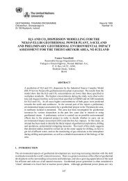
Report 16 379 Nietzen S.of the well while an attempt is made to fish out the neutralization head and weight. If that is notsuccessful, mechanical intervention is inevitable with a high cost in materials and production.One of the better alloys was Incoloy 825. This alloy has resistance to a variety of oxidizing substancessuch as nitric acid, nitrates, and oxidizing salts. The titanium addition serves, with an appropriate heattreatment, to stabilize the alloy against sensitization to intergranular corrosion (Painc Com, 2007).Also, the risk of nickel dilution during the NaOH injection was decreased, by reducing theconcentration of NaOH (from 45 to 30 % m/m). Now there is a policy of capillary change every sixmonths, independently of its state, to avoid ruptures at a later date.Fishing activitiesThe part of the neutralization system which is inside the well is based on a thin capillary tube, with aweight on the end to give it stability. Sometimes, when the system is stopped, the capillary tube maybreak. In such cases, the weight and part of the capillary remain inside the well, preventing itsreplacement with new system for chemical treatment. Hence, it is necessary to begin “fishing”activity to retrieve the broken system. The first step is to “kill” the well with fresh water to a highpressure and close the main valves. A series of tubes (approximately 3 m each) are threaded andincorporated into the well to the location of the obstruction, with a help of a hydraulic crane. Aharpoon is located at the end of the tube series. The harpoon is used to try to catch hold of the brokencapillary by means of a turning motion. When the capillary is hooked, it is taken instantly from thewell, using the crane. If the operation is successful, the well can be restarted; else the operation needsto be repeated.Scaling in casingNew studies have been conducted in order to optimize the pH value to better control corrosion andreduce scale formation. An agreement between NEDO (New Energy Development Organization,Japan) and ICE has allowed studies to be carried out to determine the rate of corrosion and scaleformation, using different values of pH in well PGM-07. Figure 9 shows the various pH values thathave made it possible to operate well PGM-07 without a mechanical cleanout for more than a year.These results are already very positive, because they indicate that the frequency of mechanical wellcleanouts can be reduced in the future, making the operation and maintenance of the acid wells lessexpensive (in the past, around 2 cleanouts per year were required for each well) (Moya et al., 2005).5045SiO 2 Scaling Rate (mg/day/dm 2 x 10 2 )40353025201510500 10 20 30 40 50 60 70Cumulative DayspH 4.5 pH 5 pH 6FIGURE 9: Channel scaling rates at different pH values in PGM-07
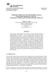
Nietzen S. 380 Report 163. DESIGN ANALYSIS3.1 Amorphous silica in the sampling system (log(Q/K))In the sampling systems, amorphous silica formation is a critical problem. One way to quantify thebeginning of amorphous silica formation at a given temperature is to estimate the saturation index, SI,for the following chemical reaction in equilibrium: The saturation index is: log log where Q= Calculated ion activity product [dimensionless] as in the following: 1 where a i = Activity of species i in solution, where i = SiO 2 (am) or SiO 2 (aq) [dimensionless];[SiO 2 ] = Concentration of silica oxide in an aqueous solution [mol/l];SiO 2 (am) = Solid silica oxide (as amorphous silica);SiO 2 (aq) = Silica oxide in an aqueous solution;K = Equilibrium constant [dimensionless].The SI value for the amorphous silica gives an estimation of the equilibrium state. Values of SI higherthan 0 represent supersaturation (formation of solids), equal to 0 represent equilibrium, and less than 0represent undersaturation (Zheng Xilai, 1993). It is possible to plot a log (Q/K) vs. temperature andto find the point of operation where the amorphous silica begins to form. The WATCH program isused for finding the different operational points of the plot. It is necessary to know the temperaturewhere the amorphous silica begins to form. The online equipment needs a sampling temperature ofabout 100°C (maximum temperature). The sample should cool down (by flashing process or heatexchange). For this reason, silica is formed in the system.Well PGM-02 shows a typical behaviour in a plot showing SI vs. temperature (Figure 10). Fordifferent SiO 2 concentrations in the samples, there are different temperatures of amorphous silicaformation, however, these differences are not very significant. In the same graph it is possible to see apH plot of PGM-02, as well as a pH plot of Well SV-11 in Svartsengi geothermal field, Iceland (bothrefer to the right axis of the graph). The data from SV-11 were taken on June 7 th 2006. The differentpH plots show different temperature dependent behaviours between the wells. These differences aredue to the distinct acids that control the pH in each fluid. For PGM-02, the important acid is H 2 SO 4which is not volatile (acid is not lost on boiling). In SV-11, the acid is H 2 CO 3 (and H 2 S); both are lostupon boiling. The chemistries are different in each case and the pH effects of the fluids are opposite.3.2 Studied scenariosIn general, the engineering design is an interactive process. The design is modified continually until itis complete with an acceptable criterion of quality defined by the factors of security, cost, convenienceand aesthetics. In the case of the sampling system, this process was applied for three differentsystems: two of them installed in well PGM-02: the other was modelled (Figure 11). Each well hasdifferent characteristics (chemical and thermohydraulic). All of Miravalles’ four wells have a low pH
Report 16 381 Nietzen S.Log (Q/K)0.30.20.10‐0.1‐0.2‐0.3‐0.46.56.36.15.95.75.55.35.14.94.7pH‐0.575 95 115 135 155 175 195 215 235 255Temperature (°C)Log(Q/K) (631.5)Log(Q/K) (601.0)Log(Q/K) (658)pH for boiling (from 235 to 165 °C) and cooling process (from 165 to 95 °C). For 631.5, 601.0 and 658.0 ppm of SiO2pH for boiling (from 238 to 165 °C) and cooling process (from 165 to 95 °C) for a normal well in Svartsengi (SV‐11), 07.06.2006FIGURE 10: SI (log(Q/K)) and pH vs. temperature for well PGM-02. For different concentrationsof SiO 2 in solution (631.5, 601.0 and 658.0 ppm in different days), it is possible to see threedifferent plots and three different temperatures where the plot crosses zero and scaling begins (at141, 136 and 145°C, respectively). Also there is a difference in the behaviour of the pH plot fordifferent wells; the acidity of the well in Svartsengi is dominated by volatile acid that is lost duringboiling, while the acidity of the well in Miravalles is dominated by a non-volatile acidthat becomes concentrated during boiling4.5in their fluids as a result of their common acid aquifer. Well PGM-02 was chosen for this study as it isthe most recent of the acid wells (with an active neutralization system) to be put into production andits fluids go to Unit 3 (Miravalles 3, private unit based on a BOT contract).FIGURE 11: Location of equipment for sampling in the well. The continuous line toward thedigital pH meter corresponds to installed equipment (flashing); the discontinuous line is thepossible location of the exchanger (no flashing). Two-phase flow is shown in red, hot water in blueand steam in green. Some pictures of the actual equipment are shown in Figure 12
Nietzen S. 382 Report 16When the neutralization process began, the fluid sample was carried to the neutralization hut through acapillary tube (a distance of 25-30 m). The equipment sensors were in the hut. During this process,several problems were encountered in the capillary tube (obstructions being the most frequent). Thestudied scenarios altered the sampling method. The main change was to conduct the measurement atthe well and to send the signal to the hut, not the fluid. Then the length of the capillary tube wasreduced while sampling (to approximately 2-3 m). With that, the obstruction problems were reducedconsiderably. It was also necessary to change the location of the equipment sensors (from the hut tothe sampling system). The scenarios are detailed in Table 3 and are shown in Figure 12.The first two systems in Table 3 (E1 and E2) use a flashing method in order to reduce the temperature;with the flashing, the sample temperature is reduced to a temperature corresponding to atmosphericpressure (around 0.94 bar, with a temperature of 97.9°C). The second system (E2) is put in the openchannel of the well (the separated water from the two-phase fluid flows through this channel, in asmall separator). The sensor takes pH readings directly from the water; the retention time is minimalin the separator. The third system reduces the sampling temperature with a heat exchange of freshwater (from 165 to 95°C); in this method, flashing is not used. The dimensions of the heat exchangerwere based on the effectiveness and number of transfer units (Perry, 1999). Calculations were carriedout using the EES program (see Appendix I).In August and September, scenarios E1 and E2 were used to collect data. Scenario E3 was designed toavoid flashing during the sampling process; however, it has not been tried to date.ABCFIGURE 12: Studied scenarios; a) E1 – measurement of pH installed near the wellhead onthe production pipe, using flashing; b) E2 – Installation in the open channel of well PGM-02,using flashing; c) E3 – Heat exchanger for reducing the sample temperature from165 to 95°C, no flashing; the connection to the well is the same as that of E1
Report 16 383 Nietzen S.TABLE 3: Equipment used in different scenariosEquipment Variable Symbol Units ValuesOutside diameter tank OD E1 m 0.1683E1 –Wall thickness thEquipment installedE1 m 0.0071Water level LWnear the wellhead (withE1 m 0.07Volume Vflashing)E1 m 3 0.001557Residence time t E1 s 45.5E2 -Equipment installednear the open channel(with flashing)E3 -Heat exchangerproposed to minimizethe flashing effectLength of the sampling tube L E2 m 6Internal tube sampling diameter di E2 m 0.0093Internal tube sampling diameter di E3 m 0.0093Final sampling temperature T ho °C 95Temperature of the cold water T ci °C 15Final cold water temperature T co °C 85Cold water flow F coldwater kg/s 0.05Typical overall heat transfer U W/(m 2·K) 1277.61Heat capacity of sampling Cp sanpling J/(kg·K) 4353Heat capacity of cold water Cp water J/(kg·K) 4184Length of the heat exchanger L E3 m 3.2263.3 ResultsScenarios with a flashing process (E1 and E2)Data from scenarios E1 and E2 (flashing process) are shown in Figures 13 and 14 for the period fromAugust 23 rd to 28 th . It is interesting to see that the pH for E1 is always lower than that of the fluid inE2 (Figure 13); the difference is not due to the calibration of equipment (both were calibrated in thetest with patron solutions of pH 4 and 7, the temperature was also calibrated with gaugedthermometers, its values were corroborated and the equipment worked correctly).The reason for the differences may be due to the chemical composition of the fluid. There are twomain components inthe fluid: non-volatiles72.56and volatiles. The acidcharacteristics of a well5depend on some4chemical compoundsdissolved in each3component; the main2non-volatile issulphuric acid and the121.510.5main volatilecomponent is CO 2 (seeTable 2). The nonvolatilecomponent is00always dissolved in theliquid phase, however,the volatile componentgoes from liquid to aEquipment installed near head well (E1)DateEquipment installed open channel (E2) Differences between equipmentsgas phase according to FIGURE 13: pH data, the data from the open channel are always higherconditions of fluid than those from the samples taken near the head; with only minorpressure. If a variations in the difference (green line), being close to the value 0.70pH22/8/07 00:0023/8/07 00:0024/8/07 00:0025/8/07 00:0026/8/07 00:0027/8/07 00:0028/8/07 00:0029/8/07 00:0030/8/07 00:00Differences in pH between equipments
Nietzen S. 384 Report 16pH5.254.84.64.44.2495 115 135 155 175 195 215 235Temperature, T (°C)Degassing coeficient = 1 Degassing coeficient = 0.01FIGURE 14: pH vs. temperature with a degassing coefficient duringa boiling process (235 to 98°C), in well PGM-02, August 10 th 2007geothermal fluid losesthe volatile part, itsacidity decreases andthe pH increases. Ananalogy can be made towhat happens withlemon juice and coke.If lemon juice is keptin contact with theatmosphere, its aciditydoes not change intime as the lemon has anon-volatile partresponsible for theacidity. However, if acoke is exposed to theatmosphere, thevolatile part (CO 2 )goes to the atmosphere,and the pH of the fluidchanges with time.The plots of Figure 13 show the effect of the non-volatile and volatile components. Scenario E1 is asmall tank with a cover; it is likely that during the flashing process some components stay in liquidphase (not all of the volatile components go to the atmosphere, the recipient is semi-closed and sometransfer phenomena could not have been carried out in a complete way). On the other hand, inscenario E2, there are two flashing processes, one of them to 7 bar-abs (separation of the steam for usein generation), and the other to atmospheric conditions towards the well’s silencer in a completelyopen system; it is guaranteed that most of the volatile component passed to the atmosphere.The data from Figure 14 show the effects of a non-equilibrium process (degassing coefficient = 0.01)in comparison with an equilibrium process (degassing coefficient = 1.0). According to the WATCHprogram, the boiling process with a degassing coefficient of 0.01 results in a lower pH than the boilingprocess with a degassing coefficient of 1. It is possible that scenario E1 does not reach equilibriumdue to its semi-closed state that is evidenced in the pH values. On the other hand, scenario E2 seemedto have complete equilibrium (degassing coefficient = 1.0). In summary, the pH readings are differentfor the two scenarios; the equipment with a complete flashing process (in theory - E2) showed lessacidity (higher pH) due to the loss of the volatile part.The temperatures of the sampling systems are almost the same for both E1 and E2 (Figure 15). Thetrendline near zero corroborates this statement (black line shows the differences between equipment).There are more variations of the tendency in the equipment close to the wellhead (E1); this behaviouris possibly due to a combination of the configuration effects (valves cross, valve production, change offluid direction, etc.), and the high residence time of the equipment (non-continuous). Of note is thatsampling temperature decreased in time for both scenarios; the outdoor temperature (changes underclimatic conditions during the test) affected the values of the sampling temperature.There is a scaling effect in both E1 and E2 with the temperature drop; however, it is not critical due totheir configurations. The solid particles were deposited in the bottom of the tank in scenario E1, andeasy to clean during maintenance; in scenario E2, the scaling process occurred in the separator and inthe open channel.
Nietzen S. 386 Report 16FIGURE 17: Profile of the sampling temperature in the heat exchanger (E3). The silica scalingbegins at 137°C, corresponding to 0.9 m of the exchanger; the vertical line in the profileshows the location in the equipmentsilica, as it is not recommended to use chemicals due to damage risk to the equipment (SverrirThórhallsson, pers. comm.). Maintenance is necessary after the efficiency of the equipment hasdecreased with time (at temperatures higher than 98-99°C). Only experience can define the timeperiod between cleaning operations in each acid well. The use of two exchangers is necessary tomaintain continuous control of the neutralization system, where one should be working while the otheris being cleaned.Acid fluids are formed by a mix of different zones in the well. One of them dominates (the maincomponent is the sulphuric acid which is not volatile). However, some zones could increase theirparticipation at any moment and change some characteristic, such as the head pressure, pH, gasescontent, etc. The effects would be reflected in the sampling system that minimizes loss by flashingnon-volatile components in the heat exchanger.3.4 Comparison of alternatives and selectionThe main features and results of the different scenarios are listed in Table 4, including also somecomparison between them (advantages and disadvantages for each feature in each one).From Table 4, it can be deduced that the heat exchanger (E3) has the highest costs (start-up, operationand maintenance) and needs external fluids (fresh water). The problem of silica scaling is also morecritical in this equipment than in the others. However, when minimizing the loss of the volatilecomponent in the geothermal fluid (that affects the acidity and the pH values), E3 would give readingscloser to the actual acidity in the system pipes.The main focus of the sampling systems is to secure the data readings and control the neutralizationsystems. For this reason, the heat exchanger (E3) should be selected, although it has somedisadvantages. The disadvantages are minimal when compared with possible costs generated in asystem out of control: silica scaling in the casing and pipes due to high pH (loss in production, cost ofmechanical intervention and cost due to the well not being in production) or corrosion in systems incontact with the fluid with low pH (damage in casing, pipes and superficial stations, with associatedcosts, and possible loss of the well).
Report 16 387 Nietzen S.TABLE 4: Main characteristics of the studied scenarios: E1, E2 and E3Priority123456FeatureDependability in thetreatment of thesampleDependence ofclimatic conditionsDependence on theseparation processof the geothermalfluidFlexibility forchanges in the well(e.g. production,chemical changes,thermohydraulic)Problems offormation of silicascaling in theequipmentNecessity of otherfluids (fresh water)E1installed nearthe wellhead(with flashing)Low – flashing system.Most of the volatilephase will be lost fromthe fluid, affecting thepH valuesLow - semi-closedsystemNo - the sampling is onthe production line ofthe two-phase fluidPoor - flashing system.Most of the volatilephase will be lost fromthe fluid, affecting thepH valuesLow - there is silicascaling. However, it iseasy to remove. Thedeposits are formed inthe tanks’s interior part.NoScenariosE2installed nearthe open channel(with flashing)Low - flashing system.Most of the volatile phasewill be lost from the fluid,affecting the pH valuesHigh - open system (silencerand open channel). The pHvalue may be influenced byambient conditions likerains, wind, etc.Yes - the sampling is in theopen channel of the well,where the separated water is.Poor - flashing system.Most of the volatile phasewill be lost from the fluid,affecting the pH valuesLow - there is silica scaling.However, it is formed in theseparator, silencer and openchannel of the well. Theeffect on the sampling tubeis minimal.NoE3heat exchanger,proposed to minimizethe flashing effectHigh - the system is notaffected by flashing.Most of the volatile phasewill stay in the liquidphaseNo - closed systemNo -the sampling wouldbe on the production lineof the two-phase fluidHigh - the system is notaffected by flashing.Most of the volatile phaseis preserved in the liquidphaseHigh - silica scaling islocated in the internalpart of the samplingcapillary tube, reducesthe efficiency with time,and increases themaintenanceAlways - water isindispensable for thecooling system.7 Maintenance costs Low - see the last row. Low - see the last row. High - see the last row.8Period ofmaintenance andfrequency9 Initial costLow - simpleequipment, few parts,scaling is located in theinterior part of the tankand easy to remove.Medium -cost of tanks, tubeconnections, supports,electrical and mech.installations, etc.Low - simple system, whichdoes not have several parts,scaling is located in theseparator, silencer and openchannel of the well.Low –cost of tube connections,supports, electrical andmechanical installations, etc.High - equipment morecomplex, with more parts.Scaling located in theinternal part of thecapillary tube whichhinders its cleaning,increasing maintenancetime and frequency.High –cost of heat exchangers,tube connections,supports, electrical andmech. installations, etcIt may be possible to find some relationships in pH readings between E1 and E3, and use theserelationships to reduce the cost and problems generated in scenario E3; however, it is first necessary toput scenario E3 into practice.
Nietzen S. 388 Report 164. CONCLUSIONSThere are three main aquifers in Miravalles geothermal field, Costa Rica. One of them has acidiccharacteristics, being an acidic sodium-chloride-sulphate aquifer (Na-Cl-SO4). Four acid productionwells are located in the vicinity of this aquifer. Their fluids have low pH and need chemical treatmentfor neutralization. The acidity is due to the presence of two main components in the fluids: nonvolatiles(originating from the sulphate part of the aquifer) and volatiles (due to the CO 2 in solution).For this reason, when the volatile part enters a gaseous phase during the flashing process (to 1 or 7bar-a), the pH of the liquid phase increases slightly.Originally, the neutralization system of the acid wells kept the pH value at around 7. However, at thispH value there were scaling problems in the casing. The production of the wells decreased over timeand mechanical intervention was inevitable (with associated costs of the intervention, the reduction ofproduction and time without production). Hence, it was necessary to change the pH value to minimizesilica scaling. This value is now between 5.5 and 6.0. For values lower than 5.5, corrosion problemswill be significant (damage in casing, pipes and superficial stations, with associated costs, adding apossible loss of the well). In contrast, for values higher than 6.0, the scaling problems will occur (lossin production, cost of mechanical intervention and cost due to the well being out of production).The sampling system is an important factor in controlling the pH value. It is indispensable for gettingreliable readings. Three scenarios were analysed, two of them based on a flashing process, the thirdone based on a cooling process. The cooling process was preferred, mainly due to the fact that itminimizes the loss of volatile components (those influencing the readings of pH) so that the readingswill be closer to the real pH values in the pipe. However, the sampling system presents somedisadvantages, the main one being silica scaling. The scaling starts at around 137°C (for well PGM-02), corresponding to 72% of total length of the equipment (with scaling problems in 2.3 m out of atotal of 3.2 m, according to the equipment temperature profile). Periodic maintenance of thisequipment would be necessary while it is in operation, to clean away scaling from the internal tube.Probably air or water for increasing the pressure would help remove the silica. Use of chemicals is notrecommended due to damage risk to the equipment.In summary, the scenario based on a cooling process (heat exchanger) should be selected to minimizethe loss of the volatile component in the geothermal fluid (which affects the acidity and the pHvalues). The disadvantages of this system are minimal when compared with possible costs generatedin a system out of control.ACKNOWLEDGEMENTSThe author would like to express his gratitude to Dr. Ingvar B. Fridleifsson (director of the UNU-GTP) and also to Mr. Lúdvík S. Georgsson (deputy director of the UNU-GTP) for the opportunity toparticipate in the geothermal training course and for the guidance and assistance extended. Specialthanks to Ms. Thórhildur Ísberg, Ms. Dorthe H. Holm and Ms. Margrét Theodóra Jónsdóttir for theirefficient and invaluable help before and during the training in Iceland. Sincere gratitude to Dr.Thráinn Fridriksson for his excellent guidance, to Dr. Gudrún Saevarsdóttir and also to Dr. MagnúsThór Jónsson for their advice and useful discussions.Gratefulness is extended to Mr. Alfredo Mainieri and Mr. Paul Moya (pioneers in the geothermal fieldfrom Costa Rica) for their confidence and support. Special thanks to Mr. Rodrigo Mora for his helpduring the evaluations. Thanks to Mr. Eddy Sánchez for the data and useful discussion and also toOperación de Campo group (especially to Mr. Eduardo Moncada and Mr. Milton Ledezma) for thesupport and the helpful tests.Finally, thanks to all the UNU Fellows 2007 for their friendship and support.
Report 16 389 Nietzen S.REFERENCESMainieri, A., 2005: Costa Rica country update report. In: Proceedings of the World GeothermalCongress 2005, Antalaya, Turkey, CD, 5 pp.Moya, P., Nietzen, F., and Sánchez, E., 2005: Development of the neutralization system forproduction wells at the Miravalles geothermal field. In: Proceedings of the World GeothermalCongress 2005, Antalaya, Turkey, CD, 5 pp.Painc Com, 2007: Corrosion resistant alloys, Incoloy® alloy 825. Painc Com, web page:http://www.painc.com/incoloy%20825.htm.Perry, R. 1999: Perry’s chemical engineers’ handbook (7th ed.). McGraw-Hill Co. Inc., USA, 2240pp.Rodríguez, A. 2006: Amorphous iron silicate scales in surface pipelines: Characterization andgeochemical constraints on formation conditions in the Miravalles geothermal field, Costa Rica.Report 19 in: Geothermal Training Iceland 2006. UNU-GTP, Iceland, 429-452.Vega Z., E., Chavarria R., L., Barrantes V., M., Molina Z., F., Hakanson, E.C., and Mora P., O.,2005: Geologic model of the Miravalles geothermal field, Costa Rica. Proceedings of the WorldGeothermal Congress 2005, Antalya, Turkey, CD, 5 pp.Zheng Xilai, 1993: Geothermometry and mineral equilibria of thermal waters from the GuanzhongBasin, China. UNU-GTP, Iceland, report 16, 33 pp."Boundary condiitons""for process"F_t=120 [kg/s]X=85 [%]D_ipipe=0.508 [m]d_itube=0.0093 [m]P_flow =700 [kPa]APPENDIX I: The EES program for design of the heat exchanger"For exchanger"T_final=95"[C]"T_coldwater=15"[C]"F_coldwater=0.05 [kg/s]U_overhall=1277.609175 "[W/m^2-K]" "from TABLE 11-3 Typical Overall Heat-TransferCoefficients in Tubular Heat Exchangers, (Perry, 1999)"Suppose"F_sample=F_tube2T_flow=TEMPERATURE(Water,x=0,P=P_flow) "[C]"rho_flow=DENSITY(Water,x=0,P=P_flow) "[kg/m^3]"area_ipipe=(pi*D_ipipe^2)/4[m^2]area_itube= (pi*d_itube^2)/4[m^2]
Nietzen S. 390 Report 16F_water=F_t*X/100 [kg/s]v_flow=F_water/rho_flow/area_ipipe"[m/s]""Flow in the tube"F_tube=v_flow*area_itubeF_tube2=F_tube*rho_flowF_tube3=F_tube*1000*60"[m^3/s]""[kg/s]""[l/min]""Find length of a concentric tube HX.knowns:"T_h_i=T_flow "[C]"T_h_o=T_final "[C]"T_c_i=T_coldwater "[C]"m_dot_h=F_sample "[kg/s]"m_dot_c=F_coldwater "[kg/s]"U=U_overhall "[W/m^2-K]"D=d_itube+0.0002 [m] "[m]"rho_oil=DENSITY(Water,T=T_coldwater,P=101.3)rho_water=rho_flow "[kg/m^3]"C_p_oil=CP(Water,T=T_coldwater,P=101.3)*1000C_p_water=CP(Water,x=0,P=P_flow)*1000"nu_oil=1e-5" "[m^2/s]""[J/kg-K]""[J/kg-K]""[kg/m^3]""nu_water=7e-7" "[m^2/s]""k_oil=0.64 " "[W/m-K]""k_water=0.134" "[W/m-K]""Pr_oil=140Pr_water=4.7""a) What is the heat transfer and the water outlet temperature?"C_h=m_dot_h*c_p_oil "[W/K]"C_c=m_dot_h*c_p_water "[W/K]"q=C_h*(T_h_i-T_h_o) "[W]"q=C_c*(T_c_o-T_c_i) "[W]""b) What is the HX length?"C_min=min(C_h, C_c)TypeHX$='counterflow'q_max=C_min*(T_h_i-T_c_i) "[W]"epsilon=q/q_max"[W/K]"Ntu=HX(TypeHX$, epsilon, C_h, C_C, 'Ntu')Ntu=(U*A)/C_minA=pi*D*L