ESSE Woodfired Cooker - Pivot Stove & Heating
ESSE Woodfired Cooker - Pivot Stove & Heating
ESSE Woodfired Cooker - Pivot Stove & Heating

Create successful ePaper yourself
Turn your PDF publications into a flip-book with our unique Google optimized e-Paper software.
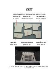
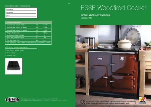
INFORMATION FOR USE WHEN ORDERING SPARES:<strong>Cooker</strong> Model:Serial Number:Colour:08/08<strong>ESSE</strong> <strong>Woodfired</strong> <strong>Cooker</strong>INSTALLATION INSTRUCTIONSMODEL: WDTechnical InformationNominal heat output (total) kW 7.9kWNominal heat output (to water) kW 3.0kWNominal heat output (to space) kW 4.9kWWeight of appliance Kg 370kgMinimum chimney draught Pa 12Mean flue gas temperature °C 164Flue gas mass flow g/s 9,8This appliance is not suitable for installation in a shared flue systemADDITIONAL SERVICEABLE PARTS1. Combuster (shown below)2. Brick Linings3. Baffle & plug<strong>ESSE</strong> Engineering Ltd. Limited, Long Ing, Barnoldswick, Lancashire BB18 6BNTel: 01282 813235 Fax: 01282 816876 Email: enquiries@esse.com Website: http://www.esse.comTHIS APPLIANCE MUST BE COMMISSIONED BY A HETAS REGISTERED ENGINEER OR A COMPETENTPERSON. THE WARRANTY CARD MUST BE RETURNED TO ENSURE GUARANTEE VALIDITYHETAS Approved
GENERAL SAFETY INFORMATIONIn the UK, the installer has a responsibility under the Health and Safety at Work Act 1974 to provide forthe safety of persons carrying out the installation. Attention is drawn to the fact that fire cement iscaustic and hands must be washed thoroughly after use. The appliance is heavy (370Kg) and caremust be taken during handling. Although the appliance does not contain asbestos products, it ispossible that asbestos may be disturbed in existing installations and every precaution must be taken.These instructions give a guide for the installation of the appliance but in no way absolve theinstaller from responsibilities to conform to British Standards, in particular BS8303 and BS6461,relating to the installation of solid fuel appliances. All local regulations including those referring tonational and European standards needs to be complied with when installing this appliance.Outside of the UK, the installer must comply with all local, national & european standards that apply.Any adjacent combustible material should be far enough away from the appliance so as not to rise65°C above the room temperature when the appliance is in operation. If necessary, any adjoiningwalls should be protected from the effects of heat. Clearances from combustible materials are20mm from the sides and 40mm from the rear.It is also recommend that a smoke alarm and appropriate fire safety equipment such as a fireextinguisher and fire blanket are installed in the kitchen as a safety precaution.Note: The illustration below provides essential boiler tapping measurements and will help whenselecting the location of the cooker. When installing a WD with a Plus2 module, pipe work will needchasing into the wall behind the Plus2.An adequate air supply for combustion and ventilation is required. As this cooker does not exceed5.0kW nominal heat output (refer to building regs document J). However, in certain circumstancesa purpose provided air vent may be necessary - for example, small or tightly sealed rooms. Airopenings provided for this purpose must not be restricted.lllllCHIMNEY AND FLUE INFORMATIONThe successful operation of the cooking appliance relies on the adequate performance of the chimneyto which it is connected. The following chimney guidelines must be followed:It should have an internal cross section of noless than 320 cm.sq (200mm dia.) If a fluelineris used, it should be 6” diameter and bemade of suitable material for burning wood).The flue diameter is 6”.Voids in the chimney should be avoided, asthese will prevent a steady flue draught. Theappliance flue pipe should pass beyond thenarrowing of the chimney.Be terminated at least 1m above roof levelso that the chimney does not terminate in apressure zone.If the appliance is installed as a freestandingappliance, it should not support any part of thechimney.Be connected to this one appliance only.lllllllBe free from cracks, severe bends, voidsand obstructions.New chimneys must be in accordance withlocal regulations.The chimney must be capped to preventingress of rain.A flue/chimney access point may also berequired so that the state of the chimney canbe checked and any fallen soot removed.External flues must be insulated to preventheat loss.Do not fit an extractor fan in the same roomas the appliance.Be a minimum 4.6m high from hob chimney levelto pot.416mm(16.5”)80mm(3.1”)7mm7mmNote: The chimney / flue to which this appliance is being connected must be swept and examinedfor soundness prior to installation. Remedial action should be taken if required, seeking expertadvice if necessary. Where the chimney is believed to have served an open fire installation it ispossible that a higher flue gas temperature from a closed appliance may loosen deposits thatwere firmly adhered, with the consequent risk of flue blockage. It is therefore recommended thatthe chimney be swept a second time within a month of regular use after installation.FLUE DRAUGHT990mm(38.9”)185mm(7.1/4”)655mm(25.3/16”)40mm(1.5”)Rp 1 Tapping(WD & W-25 Models only)Non combustible materialNon combustible materialThe chimney can be checked, before the appliance is installed, with a smoke match. If the chimneydoesn’t pull the smoke it may suggest the chimney needs attention.Note: This test is only a guide as an apparently poor flue may improve once the appliance is installed,lit and the flue is warmed. If, once the appliance is installed, there is any doubt that the chimney isproviding an adequate draught, a flue draught reading should be taken.FLUE DRAUGHT READINGTwo flue draught readings should be taken, one with the appliance at minimum firing rate and one atmaximum firing rate. The flue draught test hole must be drilled in the flue pipe as close to theappliance as possible and before any flue draught stabiliser.45mm(6”)Non combustible baseMinimum reading: The appliance should be lit and allowed to warm the flue thoroughly. Close the airslider control the flue box door and ensure firedoor is fully closed. Allow the burning rate to become25mm(1”)600mm(23.5”)905mm(35.5”)23
steady. The flue draught reading should now be taken, the minimum required is 12 pascals (0.05” w.g.).Maximum reading: The air slider control can now be opened to allow the appliance to burn atmaximum rate, and the firedoor open on the first catch. Keep the flue box door closed. Take a fluedraught reading.Ideally, the flue draught readings should range between 12 pascals, 0.12mm (0.05 in wg) and 24pascals, 2.5 mm (0.1 in wg). Any readings significantly outside this range may indicate the need forremedial action. Low flue draught symptoms: difficult to light and smoke coming into the room. Highflue draught and fuel burns away very quickly.FLUE STABILISERA flue stabiliser can be fitted to reduce the draught through the appliance if the flue draught is toohigh. The flue stabiliser should be fitted in the same room as the appliance and be the same size asthe flue pipe.CHIMNEY AND FLUE1) Pressure and suction zones created by wind2) The position of chimney outletsPOSITIONINGThe appliance should be sited on non-combustible material.INSTALLING THE APPLIANCEFLUE CONNECTIONThe flue pipe used to connect the appliance to the chimney is 6” (150mm) in diameter. (A 5”-6” adaptor issupplied to connect to the flue box of the range.The flue connection is on the top of the appliance, in the centre at the back.3) Potential causes of down draughtIMPORTANT INSTALLATION NOTES1. The installation must allow access for adequate chimney sweeping and flue cleaning.2. Avoid using bends greater than 45° to the vertical. All flue pipe sections should be as close to thevertical as possible.3. All joints in the flue system must be effectively sealed.4. All flue sockets must face upwards. On completing the installation of the appliance, the chimney,hearth and walls adjacent to the cooker must conform to local or national regulations currently in force.In the United Kingdom, the appropriate sections of the Building Regulations must be conformed to.5. Air inlet grilles should be positioned so that they are not liable to blockage.6. An air extraction device shall not be used in the same room as the appliance unless adequateadditional ventilation is provided.7. A flue cleaning door should be fitted to provide access for cleaning the flue and chimney.8. Check the appliance for soundness of seals between castings and main components and that allsupplied parts and fittings are correctly fitted.9. Ensure the appliance is left operational, the heating system correctly balanced and hand over theoperating instructions and operating tools supplied.10. Before leaving the installation demonstrate the operation of the appliance to the user. Explain allcontrols and flue way access for cleaning.4Low flue draught symptoms: difficult to light and smoke coming into the room.CauseRemedyCold chimneyLine the chimneyChimney too shortExtend the chimneyDown draughtRelocate/extend chimney terminal. Fit an anti downdraught cowlChimney diameter too largeLine the chimneyChimney obstructionClear/sweep the chimneyRestricted air supplyCheck for competing draughts (other chimneys, extractorhoods/fans). Fit an air vent if the room is sealed.High flue draught symptoms: fire difficult to control, fuel will not last, cooking too hot, appliance damage, chimney fire.CauseRemedyExternal wind conditions combined with chimney terminal Fit stabilizer cowl. Fit flue draught stabilizer.5
HOT WATER SYSTEMSTypical DHW Gravity SystemThe two connections will be supplied by your installer, both 1” BSP Female (Rp1) – on the left hand sidefor hot water. The storage cylinder should be 30-gallon nominal capacity insulated to prevent heat lossand as close to the cooker as possible. Follow general notes below, item (B) (6), (7) & (8).These appliances are not suitable for use with sealed (pressurised) systems.OPEN VENTOPEN VENTGENERAL NOTES ON WATER SYSTEM1) The cooker will produce hot water at different rates depending on how it is operated. <strong>Heating</strong> control ismanual, no thermostat is fitted.2) The system must be designed to cope with loads between the maximum and minimum output. Whenthe central heating is turned off there must be sufficient gravity load to absorb 15,000 Btu/h for periodswhen the oven is being used for cooking, e.g. Domestic hot water plus gravity operated radiator.3) An indirect storage cylinder is essential for domestic hot water supply, irrespective of whether thewater supply is hard or soft. Minimum capacity 30 gallons. Cylinder should be as close to cooker as possible.4) The central heating circuit may be gravity circulation, but a pump system is preferred. To allow heatfrom the boiler to be absorbed should there be a pump stoppage on an accelerated circuit, theprimary domestic supply must be gravity operated.5) Installation as a central heating system alone, i.e. without a domestic supply, is not recommended asthe boiler will produce heat when the cooker is in use, irrespective of central heating demand, andprimary absorption must be provided.6) Whichever system is chosen the layout must follow established heating engineering practice. Toavoid trapping air in the boiler a 1” BSP connection must be used on the flow trapping, and anyreduction in pipe size thereafter being made on a vertical rising pipe. The cooker must be level whenfitted and the flow pipe must rise from the boiler. A drain cock must be fitted on the lowest point ofthe return pipe and a vent to atmosphere at the highest point of each circuit.7) The cylinder and pipe work should be lagged to avoid heat loss.8) The static head must not exceed 60 feet of water.9) The static head must not exceed 2 bar.HEAT OUTPUT TO WATERNominal heat output to water is 3.0 kw (10,000 Btu/l). Installation procedure should follow the above, thecylinder being as near the cooker as it is possible to avoid long pipe runs and subsequent heat loss.FEED & EXPANSIONCISTERNHEATING FLOW4000 BTUGRAVITY RADHEATING RETURNDRAIN COCK AT THELOWEST POINTHOT WATERINJECTOR TEEPIPE STATSCYLINDER 35-40 GAL28MM (1 1 /4”) FLOW& RETURNFLOWRETURNCOLD WATERCISTERNDRAW OFFCOLD FEEDDRAW COCK125 MM (5”) FLUE-INTO150 MM (6”) CHIMNEYNote: A warm boiler return temperatureis essential to avoid tar deposits on theboiler faces. 45°C minimum is required.POWER FLUSH. WATER SYSTEMSIf the appliance is to be fitted onto an existing water system then it must be power flushed prior to thecommissioning of the unit and inhibitor re-added. Failure to carry out this operation will seriously affectboiler performance and negate any warranty claim.HEATINGCOOKER67