Latency for UniPHY IP, External Memory Interface Handbook
Latency for UniPHY IP, External Memory Interface Handbook
Latency for UniPHY IP, External Memory Interface Handbook

Create successful ePaper yourself
Turn your PDF publications into a flip-book with our unique Google optimized e-Paper software.
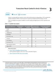
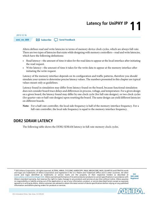
<strong>Latency</strong> <strong>for</strong> <strong>UniPHY</strong> <strong>IP</strong>112013.12.16emi_rm_009 Subscribe Send FeedbackAltera defines read and write latencies in terms of memory device clock cycles, which are always full-rate.There are two types of latencies that exists while designing with memory controllers—read and write latencies,which have the following definitions:• Read latency—the amount of time it takes <strong>for</strong> the read data to appear at the local interface after initiatingthe read request.• Write latency—the amount of time it takes <strong>for</strong> the write data to appear at the memory interface afterinitiating the write request.<strong>Latency</strong> of the memory interface depends on its configuration and traffic patterns, there<strong>for</strong>e you shouldsimulate your system to determine precise latency values. The numbers presented in this chapter are typicalvalues meant only as guidelines.<strong>Latency</strong> found in simulation may differ from latency found on the board, because functional simulationdoes not consider board trace delays and differences in process, voltage, and temperature. For a given designon a given board, the latency found may differ by one clock cycle (<strong>for</strong> full-rate designs), or two clock cycles(<strong>for</strong> quarter-rate or half-rate designs) upon resetting the board. The same design can yield different latencieson different boards.Note:For a half-rate controller, the local side frequency is half of the memory interface frequency. For afull-rate controller, the local side frequency is equal to the memory interface frequency.DDR2 SDRAM LATENCYThe following table shows the DDR2 SDRAM latency in full-rate memory clock cycles.© 2013 Altera Corporation. All rights reserved. ALTERA, ARRIA, CYCLONE, HARDCOPY, MAX, MEGACORE, NIOS, QUARTUS and STRATIX wordsand logos are trademarks of Altera Corporation and registered in the U.S. Patent and Trademark Office and in other countries. All otherwords and logos identified as trademarks or service marks are the property of their respective holders as described atwww.altera.com/common/legal.html. Altera warrants per<strong>for</strong>mance of its semiconductor products to current specifications in accordance withAltera's standard warranty, but reserves the right to make changes to any products and services at any time without notice. Altera assumesno responsibility or liability arising out of the application or use of any in<strong>for</strong>mation, product, or service described herein except as expresslyagreed to in writing by Altera. Altera customers are advised to obtain the latest version of device specifications be<strong>for</strong>e relying on any publishedin<strong>for</strong>mation and be<strong>for</strong>e placing orders <strong>for</strong> products or services.ISO9001:2008Registeredwww.altera.com101 Innovation Drive, San Jose, CA 95134
11-2DDR3 SDRAM LATENCY(1) (2)Table 11-1: DDR2 SDRAM Controller <strong>Latency</strong> (In Full-Rate <strong>Memory</strong> Clock Cycles)emi_rm_0092013.12.16<strong>Latency</strong> in Full-Rate <strong>Memory</strong> Clock CyclesRateControllerAddress &CommandPHYAddress &Command<strong>Memory</strong>MaximumReadPHY ReadReturnControllerReadReturnRound TripRound TripWithout <strong>Memory</strong>Half10EWL: 3OWL: 43–764EWL:26–30OWL:27–31EWL: 23OWL: 24Full503–741022–2619Notes to Table:1. EWL = Even write latency2. OWL = Odd write latencyDDR3 SDRAM LATENCYThe following table shows the DDR3 SDRAM latency in full-rate memory clock cycles.Table 11-2: DDR3 SDRAM Controller <strong>Latency</strong> (In Full-Rate <strong>Memory</strong> Clock Cycles)<strong>Latency</strong> in Full-Rate <strong>Memory</strong> Clock Cycles(1) (2) (3) (4)RateControllerAddress &CommandPHY Address& Command<strong>Memory</strong>MaximumReadPHY ReadReturnControllerRead ReturnRound TripRound Trip Without<strong>Memory</strong>EWER : 8EWER: 16EWER:57–63EWER: 52Quarter20EWOR: 8OWER: 115–11EWOR: 17OWER: 178EWOR:58–64OWER:61–67EWOR: 53OWER: 56OWOR: 11OWOR: 14OWOR:58–64OWOR: 53EWER: 3EWER: 7EWER:29–35EWER: 24Half10EWOR: 3OWER: 45–11EWOR: 6OWER: 64EWOR:28–34OWER:29–35EWOR: 23OWER: 24OWOR: 4OWOR: 7OWOR:30–36OWOR: 25Altera Corporation<strong>Latency</strong> <strong>for</strong> <strong>UniPHY</strong> <strong>IP</strong>Send Feedback
emi_rm_0092013.12.16LPDDR2 SDRAM LATENCY11-3<strong>Latency</strong> in Full-Rate <strong>Memory</strong> Clock CyclesRateControllerAddress &CommandPHY Address& Command<strong>Memory</strong>MaximumReadPHY ReadReturnControllerRead ReturnRound TripRound Trip Without<strong>Memory</strong>Full505–1141024–3019Notes to Table:1. EWER = Even write latency and even read latency2. EWOR = Even write latency and odd read latency3. OWER = Odd write latency and even read latency4. OWOR = Odd write latency and odd read latencyLPDDR2 SDRAM LATENCYThe following table shows the LPDDR2 SDRAM latency in full-rate memory clock cycles.Table 11-3: LPDDR2 SDRAM Controller <strong>Latency</strong> (In Full-Rate <strong>Memory</strong> Clock Cycles)<strong>Latency</strong> in Full-Rate <strong>Memory</strong> Clock Cycles(1) (2) (3) (4)RateControllerAddress &CommandPHYAddress &Command<strong>Memory</strong>MaximumReadPHY ReadReturnControllerReadReturnRound TripRound TripWithout <strong>Memory</strong>EWER: 3EWER: 7EWER:29–35EWER: 24Half10EWOR: 3OWER: 45–11EWOR: 6OWER: 64EWOR:28–34OWER:29–35EWOR: 23OWER: 24OWOR: 4OWOR: 7OWOR:30–36OWOR: 25Full505–1141024–3019Notes to Table:1. EWER = Even write latency and even read latency2. EWOR = Even write latency and odd read latency3. OWER = Odd write latency and even read latency4. OWOR = Odd write latency and odd read latencyQDR II and QDR II+ SRAM <strong>Latency</strong>The following table shows the latency in full-rate memory clock cycles.<strong>Latency</strong> <strong>for</strong> <strong>UniPHY</strong> <strong>IP</strong>Altera CorporationSend Feedback
11-4RLDRAM II <strong>Latency</strong>Table 11-4: QDR II <strong>Latency</strong> (In Full-Rate <strong>Memory</strong> Clock Cycles) (1)emi_rm_0092013.12.16<strong>Latency</strong> in Full-Rate <strong>Memory</strong> Clock CyclesRateControllerAddress &CommandPHYAddress &Command<strong>Memory</strong>MaximumReadPHY ReadReturnControllerReadReturnRound TripRound TripWithout <strong>Memory</strong>Half 1.5 RL25.51.57.001614.5Half 2.0 RL25.52.06.501614.0Half 2.5 RL25.52.56.001613.5Full 1.5 RL21.51.54.01108.5Full 2.0 RL21.52.04.51119.0Full 2.5 RL21.52.54.01118.5Note to Table:1. RL = Read latencyRLDRAM II <strong>Latency</strong>The following table shows the latency in full-rate memory clock cycles.Table 11-5: RLDRAM II <strong>Latency</strong> (In Full-Rate <strong>Memory</strong> Clock Cycles)(1) (2)<strong>Latency</strong> in Full-Rate <strong>Memory</strong> Clock CyclesRateControllerAddress &CommandPHY Address& Command<strong>Memory</strong>MaximumReadPHY ReadReturnControllerRead ReturnRound TripRound Trip Without<strong>Memory</strong>Half4EWL: 1OWL: 23–8EWL: 4OWL: 40EWL: 12–17OWL:13–18EWL: 9OWL: 10Full213–84010–157Notes to Table:1. EWL = Even write latency2. OWL = Odd write latencyRLDRAM 3 <strong>Latency</strong>The following table shows the latency in full-rate memory clock cycles.Altera Corporation<strong>Latency</strong> <strong>for</strong> <strong>UniPHY</strong> <strong>IP</strong>Send Feedback
emi_rm_0092013.12.16Table 11-6: RLDRAM 3 <strong>Latency</strong> (In Full-Rate <strong>Memory</strong> Clock Cycles)<strong>Latency</strong> in Full-Rate <strong>Memory</strong> Clock CyclesVariable Controller <strong>Latency</strong>11-5RatePHY Address &Command<strong>Memory</strong>MaximumReadPHY ReadReturnControllerRead ReturnRound TripRound Trip Without<strong>Memory</strong>Quarter73–1618028–4125Half43–166013–2610Variable Controller <strong>Latency</strong>The variable controller latency feature allows you to take advantage of lower latency <strong>for</strong> variations designedto run at lower frequency. When deciding whether to vary the controller latency from the default value of1, be aware of the following considerations:• Reduced latency can help achieve a reduction in resource usage and clock cycles in the controller, butmight result in lower fMAX.• Increased latency can help acheive greater fMAX, but might consume more clock cycles in the controllerand result in increased resource usage.If you select a latency value that is inappropriate <strong>for</strong> the target frequency, the system displays a warningmessage in the text area at the bottom of the parameter editor.You can change the controller latency by altering the value of the Controller <strong>Latency</strong> setting in the ControllerSettings section of the General Settings tab of the QDR II and QDR II+ SRAM controller with <strong>UniPHY</strong>parameter editor.Document Revision HistoryDateDecember 2013November 2012June 2012November 2011Version2013.12.162.12.01.0Updated latency data <strong>for</strong> QDR II/II+.Changes• Added latency in<strong>for</strong>mation <strong>for</strong> RLDRAM 3.• Changed chapter number from 9 to 11.• Added latency in<strong>for</strong>mation <strong>for</strong> LPDDR2.• Added Feedback icon.• Consolidated latency in<strong>for</strong>mation from 11.0 DDR2 and DDR3 SDRAMController with <strong>UniPHY</strong> User Guide, QDR II and QDR II+ SRAMController with <strong>UniPHY</strong> User Guide, and RLDRAM II Controller with<strong>UniPHY</strong> <strong>IP</strong> User Guide.• Updated data <strong>for</strong> 11.1.<strong>Latency</strong> <strong>for</strong> <strong>UniPHY</strong> <strong>IP</strong>Send FeedbackAltera Corporation