RS485 & Modbus Protocol Guide - Crompton
RS485 & Modbus Protocol Guide - Crompton
RS485 & Modbus Protocol Guide - Crompton
- No tags were found...

You also want an ePaper? Increase the reach of your titles
YUMPU automatically turns print PDFs into web optimized ePapers that Google loves.
Introducing the MODBUS <strong>Protocol</strong>This document is intended to provide an introduction to the MODBUS implementation of Integra and SPRproducts. The document was generated in response to repeated questions from the field. The section atthe end of the document, “When things go wrong”, identifies a number of potential problems some ofwhich have been experienced in the field.The MODBUS protocol “defines a message structure that controllers will recognise and use, regardless ofthe type of networks over which they communicate. It describes the process a controller uses to requestaccess to another device, how it will respond to requests from the other devices, and how errors will bedetected and reported. It establishes a common format for the layout and contents of message fields.” -<strong>Modbus</strong> <strong>Protocol</strong> Reference <strong>Guide</strong>, PI-MBUS-300 Rev. J. This document may be purchased from“Groupe Schneider, Basingstoke, England 44 (0) 1256 843184.There are a number of hardware configurations used for MODBUS networks, this guide will consider onlythe two wire <strong>RS485</strong> network as that is the configuration currently supported by the SPR and Integra familyof products.MODBUS is a trademark of AEG Schneider Automation IncPage 3 of 35 <strong>RS485</strong> <strong>Guide</strong> 07/02 Rev 6
ContentsINTRODUCING THE MODBUS PROTOCOL.................................................................................................................3CONTENTS ....................................................................................................................................................................4WHAT IS <strong>RS485</strong>?...........................................................................................................................................................5WHAT IS HALF DUPLEX?.............................................................................................................................................5CONNECTING THE INSTRUMENTS.............................................................................................................................5WHICH IS A AND WHICH IS B?....................................................................................................................................6MODBUS MESSAGES...................................................................................................................................................7MODBUS MESSAGE FORMAT .....................................................................................................................................7THE SERIAL TRANSMISSION MODES ........................................................................................................................9ASCII MODE .................................................................................................................................................................9RTU MODE .................................................................................................................................................................10MODBUS MESSAGE TIMING (RTU MODE)....................................................................................................................10HOW CHARACTERS ARE TRANSMITTED SERIALLY ............................................................................................................11ERROR CHECKING METHODS ........................................................................................................................................11PARITY CHECKING........................................................................................................................................................12FUNCTION CODES......................................................................................................................................................13PRODUCT SPECIFIC CONSIDERATIONS. ................................................................................................................13MODBUS COMMANDS SUPPORTED ........................................................................................................................15READ INPUT REGISTERS ...............................................................................................................................................15READ HOLDING REGISTERS...........................................................................................................................................16WRITE HOLDING REGISTERS .........................................................................................................................................17DIAGNOSTICS...............................................................................................................................................................18WHEN THINGS GO WRONG.......................................................................................................................................19PRODUCT INFORMATION ..........................................................................................................................................20EXCEPTION CODES.......................................................................................................................................................20START UP CONSIDERATIONS. ........................................................................................................................................20IDENTIFYING IMPORTING, EXPORTING, LEADING AND LAGGING..........................................................................................21LINE TO LINE AND LINE TO NEUTRAL VOLTAGES: .............................................................................................................21INSTRUMENT MODBUS REGISTERS.................................................................................................................................21INPUT REGISTERS ........................................................................................................................................................21HOLDING REGISTERS....................................................................................................................................................22HOLDING REGISTERS SPECIFIC TO THE 1560 /1580........................................................................................................22HOLDING REGISTER SPECIFIC TO THE SPR.....................................................................................................................25APPENDIX A: INSTRUMENT INPUT REGISTERS .....................................................................................................29APPENDIX B: INSTRUMENT HOLDING REGISTERS ...............................................................................................34Page 4 of 35 <strong>RS485</strong> <strong>Guide</strong> 07/02 Rev 6
What is <strong>RS485</strong>?<strong>RS485</strong> or EIA (Electronic Industries Association) <strong>RS485</strong> is a balanced line, half-duplex transmissionsystem allowing transmission distances of up to 1.2 km. The following table summarises the RS-485Standard:PARAMETERMode of OperationNumber of Drivers and ReceiversMaximum cable length (metres) 1200Maximum data rate (baud)Differential32 Drivers,32 Receivers10 MMaximum common mode voltage (Volts) 12 to -7Minimum Driver Output Levels (Loaded) +/- 1.5Minimum Driver Output Levels(Unloaded)Drive Load (Ohms)Driver Output short circuit current Limit(mA)Minimum receiver input Resistance(kohms)Receiver sensitivity+/- 660 (min)150 to Gnd, 250 to -7 or 12 V12+/- 200mvFurther information relating to <strong>RS485</strong> may be obtained from either the EIA or the various <strong>RS485</strong> devicemanufacturers:• Texas Instruments• Maxim SemiconductorsWhat is half duplex?Half duplex is a system in which one or more transmitters (talkers) can communicate with one or morereceivers (listeners) with only one transmitter being active at any one time. For example, a “conversation”is started by asking a question, the person who has asked the question will then listen until he gets ananswer or until he decides that the individual who was asked the question is not going to reply.In a 485 network the “master” will start the “conversation” with a “Query” addressed to a specific “slave”,the “master” will then listen for the “slave’s” response. If the “slave” does not respond within a pre-definedperiod, (set by control software in the “master”), the “master” will abandon the “conversation”.Connecting the InstrumentsScreened twisted pair cable should be used. All “A” connections should be connected together using oneconductor of the twisted pair cable, all “B” connections should be connected together using the otherconductor in the pair. The cable screen should be connected to the “Gnd” terminal.Page 5 of 35 <strong>RS485</strong> <strong>Guide</strong> 07/02 Rev 6
A Belden 9841 (Single pair) or 9842 (Two pair) cable with a characteristic impedance of 120 ohms isrecommended, the cable should be terminated at each end with a 120 ohm, quarter watt (or greater)resistor.There must be no more than two wires connected to each terminal, this ensures that a “Daisy Chain or“straight line” configuration is used. A “Star” or a network with “Stubs (Tees)” is not recommended asreflections within the cable may result in data corruption.Which is A and Which is B?The A and B connections to the SPR and Integra Products can be identified by the signals present onthem whilst there is activity on the <strong>RS485</strong> bus:Page 6 of 35 <strong>RS485</strong> <strong>Guide</strong> 07/02 Rev 6
MODBUS MessagesCommunication on a MODBUS Network is initiated (started) by a “Master” with a “query” to a “Slave”. The“Slave “ which is constantly monitoring the network for “Queries” will recognise only the “Queries”addressed to it and will respond either by performing an action (setting a value for example) or byreturning a “response”. Only the Master can initiate a query.In the MODBUS protocol the master can address individual slaves, or, using a special “Broadcast”address, can initiate a broadcast message to all slaves. The SPR and Integra products do not support thebroadcast address.MODBUS Message FormatThe MODBUS protocol defines the format for the master’s query and the slave’s response.The query contains the device (or broadcast) address, a function code defining the requested action, anydata to be sent, and an error-checking field.The response contains fields confirming the action taken, any data to be returned, and an error-checkingfield. If an error occurred in receipt of the message, or if the slave is unable to perform the requestedaction, the slave will construct an error message and send it as its response.QueryThe example illustrates a request for a single 16-bit <strong>Modbus</strong> Register.SlaveAddressFunctionCodeStartAddress(Hi)StartAddress(Lo)Numberof Points(Hi)Numberof Points(Lo)ErrorCheck(Lo)ErrorCheck(Hi)Slave Address:Function Code:Start Address (Hi):Start Address (Lo):8-bit value representing the slave being addressed (1 to 247), 0 is reserved forthe broadcast address. The SPR and Integra products do not support thebroadcast address.8-bit value telling the addressed slave what action is to be performed. (3, 4, or16 are valid for Integra)The top (most significant) eight bits of a 16-bit number specifying the startaddress of the data being requested.The bottom (least significant) eight bits of a 16-bit number specifying the startaddress of the data being requested.Page 7 of 35 <strong>RS485</strong> <strong>Guide</strong> 07/02 Rev 6
Number of Points (Hi): The top (most significant) eight bits of a 16-bit number specifying the number ofregisters being requested.Number of Points (Lo): The bottom (least significant) eight bits of a 16-bit number specifying the numberof registers being requested.Error Check (Lo):Error Check (Hi):The bottom (least significant) eight bits of a 16-bit number representing the errorcheck value.The top (most significant) eight bits of a 16-bit number representing the errorcheck value.ResponseThe example illustrates the normal response to a request for a single 16-bit Register.SlaveAddressFunctionCodeByteCountData (Hi)Data(Lo)ErrorCheck(Lo)ErrorCheck(Hi)Slave Address:Function Code:Byte Count:Data (Hi):Data (Lo):Error Check (Lo):Error Check (Hi):Exception Response8-bit value representing the address of slave, which has just responded.8-bit value which, when a copy of the function code in the query, indicates thatthe slave recognised the query and has responded. (See also ExceptionResponse).8-bit value indicating the number of data bytes contained within this responseThe top (most significant) eight bits of a 16-bit number representing theregister(s) requested in the query.The bottom (least significant) eight bits of a 16-bit number representing theregister(s) requested in the query.The bottom (least significant) eight bits of a 16-bit number representing the errorcheck value.The top (most significant) eight bits of a 16-bit number representing the errorcheck value.If an error is detected in the content of the query (excluding parity errors and Error Check mismatch), thefunction code will be modified to indicate that the response is an error response (called an exceptionresponse), and the data bytes will contain a code that describes the error. The exception response isidentified by the function code being a copy of the query function code but with the most-significant bit setto logic ‘1’.SlaveAddressFunctionCode’Error CodeErrorCheck (Lo)ErrorCheck (Hi)Slave Address:8-bit value representing the address of slave, which has just responded.Page 8 of 35 <strong>RS485</strong> <strong>Guide</strong> 07/02 Rev 6
Function Code: 8 bit value which is the function code in the query OR'ed with Hex (80),indicating the slave either does not recognise the query or could not carry outthe action requested.Error Code:Error Check (Lo):Error Check (Hi):The Serial Transmission Modes8-bit value indicating the nature of the exception detected. (See “ExceptionCodes“ in the section “Product Information for a list of SPR and Integrasupported codes).The bottom (least significant) eight bits of a 16-bit number representing the errorcheck value.The top (most significant) eight bits of a 16-bit number representing the errorcheck value.There are two MODBUS serial transmission modes, ASCII and RTU.ASCII ModeIn ASCII (American Standard Code for Information Interchange) mode, each 8-bit byte in a message issent as two ASCII characters. The main advantages of this mode are that it allows time intervals of up toone second to occur between characters without causing a timeout error and that messages may bemonitored more easily on a simple ASCII terminal.In ASCII mode messages begin with the ‘:’ character (Hex (3A)) and end with a Carriage Return – LineFeed pair (Hex (0D) and Hex (0A)).The format for each byte in ASCII mode is:Coding System:Bits per Byte:Error Check Field:Hexadecimal, ASCII characters 0-9, A-F Onehexadecimal character contained in each ASCIIcharacter of the message, each 8-bit byte to betransmitted requires two characters.1 start bit7 data bits, least significant bit sent first1 parity bit for even/odd parity; no parity bit for noparity,1 stop bit if parity is used; 2 stop bits if no parityLongitudinal Redundancy Check (LRC)The SPR and Integra products do not support the ASCII mode.Page 9 of 35 <strong>RS485</strong> <strong>Guide</strong> 07/02 Rev 6
RTU ModeIn RTU (Remote Terminal Unit) mode, each 8-bit byte in a message contains two 4-bit hexadecimalcharacters. The main advantage of this mode is that its greater character density allows better datathroughput than ASCII for the same baud rate, however each message must be transmitted in acontinuous stream.The format for each byte in RTU mode is:Coding System:Bits per Byte:Error Check Field:8-bit binary, hexadecimal 0-9, A-F Two hexadecimalcharacters contained in each 8-bit field of themessage1 start bit,8 data bits, least significant bit sent first1 parity bit for even/odd parity; no parity bit for noparity1 stop bit if parity is used; 2 stop bits if no parityCyclical Redundancy Check (CRC)The SPR and Integra products support MODBUS RTU mode. Integra additionally supports a commonalternative format with 1 stop bit and no parity.MODBUS Message Timing (RTU Mode)A MODBUS message has defined beginning and ending points. The receiving devices recognise the startof the message, read the “Slave Address” to determine if they are being addressed and know when themessage is completed so that they can use the Error Check bytes to confirm the integrity of the query.Partial messages can be detected and discarded:In RTU mode, messages start with a silent interval of at least 3.5 character times.The first field then transmitted is the device address.The allowable characters transmitted for all fields are hexadecimal 0-9, A-F. Devices monitor the networkbus continuously, including during the ‘silent’ intervals. When the first field (the address field) is received,each device decodes it to find out if it is the addressed device. If the device determines that it is the onebeing addressed it decodes the whole message and acts accordingly, if it is not being addressed itcontinues monitoring for the next message.Following the last transmitted character, a silent interval of at least 3.5 character times marks the end ofthe message. A new message can begin after this interval.In the Integra 1000 and 2000, a silent interval of 60msec minimum is required in order to guaranteesuccessful reception of the next request.The entire message frame must be transmitted as a continuous stream. If a silent interval of more than 1.5character times occurs before completion of the frame, the receiving device flushes the incompletemessage and assumes that the next byte will be the address field of a new message.Similarly, if a new message begins earlier than 3.5 character times following a previous message, thereceiving device will consider it a continuation of the previous message. This will result in an error, as thevalue in the final CRC field will not be valid for the combined messages.Page 10 of 35 <strong>RS485</strong> <strong>Guide</strong> 07/02 Rev 6
How Characters are Transmitted SeriallyWhen messages are transmitted on standard MODBUS serial networks each character or byte is sent inthis order (left to right):With Parity Checking (11 bit characters):Least Significant Bit (LSB)Most Significant Bit (MSB)Start 1 2 3 4 5 6 7 8 Parity StopWithout Parity Checking, 2 Stop Bits (11 bit characters):Start 1 2 3 4 5 6 7 8 Stop StopThe Integra products additionally support No parity, One stop bit.Without Parity Checking, 1 Stop Bit (10 bit characters):Start 1 2 3 4 5 6 7 8 StopError Checking MethodsStandard MODBUS serial networks use two error checking processes, the error check bytes mentionedabove check message integrity whilst Parity checking (even or odd) can be applied to each character inthe message.The master is configured by the user to wait for a predetermined timeout interval. The master will wait forthis period of time before deciding that the slave is not going to respond and that the transaction should beaborted. Care must be taken when determining the timeout period from both the master and the slaves’specifications. The slave may define the ‘response time’ as being the period from the receipt of the last bitof the query to the transmission of the first bit of the response. The master may define the ‘response time’as period between transmitting the first bit of the query to the receipt of the last bit of the response. It canbe seen that message transmission time, which is a function of the baud rate, must be included in thetimeout calculation.Page 11 of 35 <strong>RS485</strong> <strong>Guide</strong> 07/02 Rev 6
Parity CheckingIf parity checking is enabled - either Even or Odd Parity is specified - the quantity of “1’s” will be counted inthe data portion of each of the eight bits in the character. The parity bit will then be set to a 0 or 1 to resultin an Even or Odd total of “1’s”.Note that parity checking can only detect an error if an odd number of bits are picked up or dropped in acharacter frame during transmission, if for example two 1’s are corrupted to 0’s the parity check will notfind the error.If No Parity checking is specified, no parity bit is transmitted and no parity check can be made. Anadditional stop bit is transmitted to fill out the character frame when 2 stop bits are selected.If No Parity checking is specified and one stop bit is selected the character is effectively shortened by onebit.CRC CheckingThe error check bytes of the MODBUS messages contain a Cyclical Redundancy Check (CRC) value thatis used to check the content of the entire message. The error check bytes must always be present tocomply with the MODBUS protocol; there is no option to disable it.The error check bytes represent a 16-bit binary value, calculated by the transmitting device. The receivingdevice must recalculate the CRC during receipt of the message and compare the calculated value to thevalue received in the error check bytes. If the two values are not equal, the message should bediscarded.The error check calculation is started by first pre-loading a 16-bit register to all 1’s (i.e. Hex (FFFF)) eachsuccessive 8-bit byte of the message is applied to the current contents of the register. Note: only the eightbits of data in each character are used for generating the CRC, start bits, stop bits and the parity bit, if oneis used, are not included in the error check bytes.During generation of the error check bytes, each 8-bit character is exclusive OR'ed with the registercontents. The result is shifted in the direction of the least significant bit (LSB), with a zero filled into themost significant bit (MSB) position. The LSB prior to the shift is extracted and examined. If the LSB was a1, the register is then exclusive OR'ed with a pre-set, fixed value. If the LSB was a 0, no exclusive ORtakes place.This process is repeated until eight shifts have been performed. After the last (eighth) shift, the next 8-bitbyte is exclusive OR'ed with the register’s current value, and the process repeated. The final contents ofthe register, after all the bytes of the message have been applied, is the error check value.In the following pseudo code “ErrorWord” is a 16-bit value representing the error check values.BEGINErrorWord = Hex (FFFF)FOR Each byte in messageErrorWord = ErrorWord XOR byte in messageFOR Each bit in byteLSB = ErrorWord AND Hex (0001)IF LSB = 1 THEN ErrorWord = ErrorWord – 1ErrorWord = ErrorWord / 2IF LSB = 1 THEN ErrorWord = ErrorWord XOR Hex (A001)NEXT bit in byteNEXT Byte in messageENDPage 12 of 35 <strong>RS485</strong> <strong>Guide</strong> 07/02 Rev 6
Function CodesThe function code part of a MODBUS message defines the action to be taken by the slave. The SPR andIntegra products support the following function codes:Code MODBUS name Description03 Read HoldingRegistersRead the contents of read/write location(4X references)04 Read Input Registers Read the contents of read only location(3X references)08 Diagnostics Only sub-function zero is supported. Thisreturns the data element of the queryunchanged.16 Pre-set MultipleRegistersSet the contents of read/write location(4X references)Product Specific Considerations.The MODBUS protocol defines “Registers” for the variables; a register is 16 bits long. As a 16-bit numberwould prove restrictive for the power parameters measured (maximum of 65535) there are a number ofapproaches, which have been adopted to overcome this restriction. The <strong>Crompton</strong> products use twoconsecutive registers to represent a floating-point number, effectively expanding the range to +/- 1x10 37 .The values produced by the <strong>Crompton</strong> products can be used directly without any requirement to “scale”the values, for example, the units for the voltage parameters are volts, the units for the power parametersare watts etc.What is a floating point Number?A floating-point number is a number with two parts, a mantissa and an exponent and is written in the form1.234 x 10 5 . The mantissa (1.234 in this example) must have the decimal point moved to the right with thenumber of places determined by the exponent (5 places in this example) i.e. 1.234x 10 5 = 123400. If theexponent is negative the decimal point is moved to the left.What is an IEEE 754 format floating-point number?An IEEE 754 floating point number is the binary equivalent of the floating-point number shown above. Themajor difference being that the most significant bit of the mantissa is always arranged to be 1 and is thusnot included in the representation of the number. The process by which the most significant bit isarranged to be 1 is called normalisation; the mantissa is thus referred to as a “normal mantissa”. Duringnormalisation the bits in the mantissa are shifted to the left whilst the exponent is decremented until themost significant bit is one. In the special case where the number is zero both mantissa and exponent arezero.Page 13 of 35 <strong>RS485</strong> <strong>Guide</strong> 07/02 Rev 6
The bits in an IEEE 754 format have the following significance:Where:SEMData Hi Word, Hi Data Hi Word, Data Lo Word, Data Lo Word,ByteLo Byte Hi ByteLo ByteSEEE EEEE EMMM MMMM MMMM MMMM MMMM MMMMrepresents the sign bit where 1 is negative and 0 is positiveis the two’s complement exponent with an offset of 127 i.e. an exponent of zero is represented by127, an exponent of 1 by 128 etc.is the 23-bit normal mantissa. The highest bit is always 1 and, therefore, is not stored.Using the above format the floating point number 240.5 is represented as :Data Hi Word, Hi Data Hi Word, Data Lo Word, Data Lo Word,ByteLo Byte Hi ByteLo Byte43 70 80 00The following example demonstrates how to convert floating-point numbers from their hexadecimalstorage equivalents. For this example, we will use the value for 240.5 shown aboveNote that the floating-point storage representation is not an intuitive format. To convert this value to afloating-point number, the bits should be separated as specified in the floating-point number storageformat table shown above. For example:Data Hi Word,Data Hi Word,Data Lo Word,Data Lo Word,Hi ByteLo ByteHi ByteLo Byte0100 0011 0111 0000 1000 0000 0000 0000From this you can determine the following information.• The sign bit is 0, indicating a positive number.• The exponent value is 10000110 binary or 134 decimal. Subtracting 127 from 134 leaves 7, which isthe actual exponent.• The mantissa appears as the binary number 11100001000000000000000There is an implied decimal point at the left of the mantissa that is always preceded by a 1. This digit is notstored in the hexadecimal representation of the floating-point number. Adding 1 and the decimal point tothe beginning of the mantissa gives the following:1.11100001000000000000000Now, we adjust the mantissa for the exponent. A negative exponent moves the decimal point to the left. Apositive exponent moves the decimal point to the right. Because the exponent is 7, the mantissa isadjusted as follows:11110000.1000000000000000Page 14 of 35 <strong>RS485</strong> <strong>Guide</strong> 07/02 Rev 6
Finally, we have a binary floating-point number. Binary digits that are to the left of the decimal pointrepresent the power of two corresponding to their position. For example, 11110000 represents (1 x 27) +(1 x 26) + (1 x 25) + (1 x 24) + (0 x 23)+ (0 x 22) + (0 x 21)+ (0 x 20) = 240.Binary digits that are to the right of the decimal point also represent a power of 2 corresponding to theirposition. As the digits are to the right of the decimal point the powers are negative. For example: 100represents (1 x 2-1) + (0 x 2-2)+ (0 x 2-3) + … which equals 0.5.Adding these two numbers together and making reference to the sign bit produces the number +240.5.For each floating point value requested two MODBUS registers or points (four bytes) must be requested.The received order and significance of these four bytes for the SPR and Integra products 1 is shown below:Data Hi Word,Data Hi Word,Data Lo Word,Data Lo Word,Hi ByteLo ByteHi ByteLo ByteMODBUS Commands supportedAll <strong>Crompton</strong> Integra Instruments support the “Read Input Register” (3X registers), the “Read HoldingRegister” (4X registers) and the “Pre-set Multiple Registers” (write 4X registers) commands of theMODBUS RTU protocol. All values stored and returned are in floating point format to IEEE 754 with themost significant byte first 2 .Read Input RegistersMODBUS code 04 reads the contents of the 3X registers.ExampleThe following query will request ‘Volts 1’ from an instrument with node address 1:Field NameSlave Address 01Function 04Starting Address High 00Starting Address Low 00Number of Points High 00Number of Points Low 02Error Check Low 71Error Check HighExample (Hex)Note: Data must be requested in register pairs i.e. the “Number of Points” must be even to request afloating point variable. If the “Number of points” is odd or the “Starting Address” falls in the middle of afloating point variable the product will return an error message.CB1 The Integra 1500 Series supports the ability to reverse the word order. In reversed mode the words are transmitted and receivedData Lo Word followed by Data Hi Word.2 Except where the instrument is an Integra 1500 Series configured for reversed mode.Page 15 of 35 <strong>RS485</strong> <strong>Guide</strong> 07/02 Rev 6
The following response returns the contents of Volts 1 as 230.2Field NameExample (Hex)Slave Address 01Function 04Byte Count 04Data, High Word, High Byte 43Data, High Word, Low Byte 66Data, Low Word, High Byte 33Data, Low Word, Low Byte 34Error Check Low1BError Check High 38Read Holding RegistersMODBUS code 03 reads the contents of the 4X registers.ExampleThe following query will request the prevailing ‘Demand Time’:Field NameExample (Hex)Slave Address 01Function 03Starting Address High 00Starting Address Low 00Number of Points High 00Number of Points Low 02Error Check LowC4Error Check High0BNote: Data must be requested in register pairs i.e. the “Number of Points” must be even to request afloating point variable. If the “Number of points” is odd or the “Starting Address” falls in the middle of afloating point variable the Integra products will return an error message.The following response returns the contents of Demand Time as 1Field NameExample (Hex)Slave Address 01Function 03Byte Count 04Data, High Word, High Byte 3FData, High Word, Low Byte 80Data, Low Word, High Byte 00Data, Low Word, Low Byte 00Error Check LowF7Error Check HighCFPage 16 of 35 <strong>RS485</strong> <strong>Guide</strong> 07/02 Rev 6
Write Holding RegistersMODBUS code 16 decimal (10 Hex) writes the contents of the 4X registers.ExampleThe following query will set the Demand Time to zero, which effectively resets the Demand Period:Field NameExample (Hex)Slave Address 01Function 10Starting Address High 00Starting Address Low 00Number of Registers High 00Number of Registers Low 02Byte Count 04Data, High Word, High Byte 00Data, High Word, Low Byte 00Data, Low Word, High Byte 00Data, Low Word, Low Byte 00Error Check Low3DError Check High 23Note: Data must be written in register pairs i.e. the “Number of Points” must be even to set a floatingpoint variable. If the “Number of points” is odd or the “Starting Address” falls in the middle of a floatingpoint variable the Integra products will return an error message.The following response indicates that the write has been successful.Field NameExample (Hex)Slave Address 01Function 10Starting Address High 00Starting Address Low 00Number of Registers High 00Number of Registers Low 02Error Check Low 41Error Check HighC8Page 17 of 35 <strong>RS485</strong> <strong>Guide</strong> 07/02 Rev 6
DiagnosticsMODBUS code 08 provides a number of diagnostic sub-functions. Only the “Return Query Data” subfunction(sub-function 0) is supported on the Integra 1540, 1560, 1580.ExampleThe following query will send a diagnostic “return query data” query with the data elements set to Hex(AA)and Hex(55) and will expect these to be returned in the response:Field NameSlave Address 01Function 08Sub-Function High 00Sub-Function Low 00Data Byte 1Example (Hex)AAData Byte 2 55Error Check Low5EError Check High 94Note: Data must be written in register pairs i.e. the “Number of Points” must be even. If the “Number ofpoints” is odd or the “Starting Address” falls in the middle of a floating point variable product will return anerror message.The following response indicates the correct reply to the query.Field NameExample (Hex)Slave Address 01Function 08Sub-Function High 00Sub-Function Low 00Data Byte 1AAData Byte 2 55Error Check Low5EError Check High 94Page 18 of 35 <strong>RS485</strong> <strong>Guide</strong> 07/02 Rev 6
When things go wrong• Start with a simple network, one master and one slave, with SPR and Integra products this is easilyachieved as the network can be left intact whilst individual instruments are disconnected by removingthe <strong>RS485</strong> connector from the rear of the instrument.• Check that all the “A’s” are connected together, check that all the “B’s” are connected together, checkthat all the “Gnd’s” are connected together.• If using SpecView or PCView (PC software) with a RS232 to <strong>RS485</strong> converter confirm that the data“transmitted” onto the <strong>RS485</strong> is not echoed back to the PC on the RS232 lines. (This facility issometimes a link option within the converter). Many PC based packages seem to be “confused” whenthey receive an echo of the message they are transmitting.• Confirm that the Address of the instrument is the same as the “master” is expecting.• If the “network” operates with one instrument but not more than one check that each instrument has aunique address.• Each request for data must be restricted to 20 parameters (40 in the case of the 1500 Series) or less.Violating this requirement will impact the performance of the instrument and may result in a responsetime in excess of the specification.• Check that the MODBUS mode (RTU or ASCII) and serial parameters (baud rate, number of databits, number of stop bits and parity) are the same for all devices on the network.• Check that the “master” is requesting floating-point variables (pairs of registers placed on floatingpoint boundaries) and is not “splitting” floating point variables.• Check that the floating-point byte order expected by the “master” is the same as that used by theSPR and Integra products. (PCView and Citect packages can use a number of formats including thatsupported by SPR and Integra).• If possible obtain a second RS232 to <strong>RS485</strong> converter and connect it between the <strong>RS485</strong> bus and anadditional PC equipped with a software package, which can display the data on the bus. Check forthe existence of valid requests.Page 19 of 35 <strong>RS485</strong> <strong>Guide</strong> 07/02 Rev 6
Product InformationThe following section outline the general information about the use of <strong>Modbus</strong> with the products coveredby this guide. It also outlines the information available over the <strong>Modbus</strong> interface of the products.Appendix A and B, provides a cross-reference as to which features are available over the <strong>Modbus</strong>interface for individual models.On the instrument, each electrical parameter measured or calculated and each configuration parameter isgiven a number that maps onto a <strong>Modbus</strong> address. To convert a <strong>Crompton</strong> Parameter number into a<strong>Modbus</strong> address, subtract one from the parameter number and double it.Exception CodesWhenever an SPR or Integra product receives a MODBUS message with valid parity and error check butwhich contains some other error (e.g. a request to set a register to an illegal value or a request for part ofa floating point variable), an Exception code will be generated. (The message format is shown in themessage Formats section)Exceptions are indicated by a value in the function code field of the response greater than Hex (80),obtained by OR'ing the original function code in the query with Hex (80). For example, if a function code ofHex (84) and exception code 2 were present in an exception response this indicates that a function 4query (Read Holding Registers) has resulted in an illegal data address error.The error codes and the corresponding types of error returned by the models covered in this guide aregiven in the following table:ExceptionCodeMODBUS name Description Reported by01Illegal Function02 Illegal DataAddressThe function code is not supported bythe productAttempt to access an invalid address oran attempt to read or write part of afloating point value03 Illegal Data Value Attempt to set a floating point variable toan invalid value05 Slave DeviceFailureAn error occurred when the instrumentattempted to store an update to it’sconfiguration1000, 2000,1540, 1560,15801000, 2000,1540, 1560,15801000, 2000,1540, 1560,15801540, 1560,1580Start Up Considerations.The products covered by this guide do not require any special start up messages; the “master” simplyrequests the data it requires.On power up the Integra 1560 and 1580 have a Display Auto Detect facility. For about five seconds theinstrument will monitor but not reply to <strong>Modbus</strong> queries. If it detects a <strong>Crompton</strong> display unit is powered upand attached, the communication settings on that port will be fixed to 9600 baud, 1 start, 2 stop and noparity until the instrument is powered down.If the display auto detect period expires without a display unit being detected, the Integra 1560 and 1580will set-up the port(s) to use the communication parameters previously configured by the user.Page 20 of 35 <strong>RS485</strong> <strong>Guide</strong> 07/02 Rev 6
Identifying Importing, Exporting, Leading and Lagging.The products generate signed values for Watts and VAr that may be used to indicate the direction ofpower flow (Import or Export) and whether the load is inductive (current lagging voltage) or capacitive(current leading voltage). The following table provides a key to determining these characteristics used withthe respective Phase Angle and Power Factor displays.Sign of Watts Sign of Vacs Direction ofPower FlowCurrent Lead/Lag+ve +ve Import Lagging+ve -ve Import Leading-ve +ve Export Leading-ve -ve Export LaggingLine to Line and Line to Neutral Voltages:On a 3 phase 4 wire system parameters 1-3 will contain the measured parameters, that is the Line toNeutral voltages, the values of parameters 22, 23, 55-60, 67-70 will also refer to line to neutral values.The values contained in parameters 101-112 will be calculated from the line to neutral voltages andrepresent the line to line values.On a 3 phase 3 wire system parameters 1-3 will contain the measured parameters, that is the Line to Linevoltages, the values of parameters 22, 23, 55-60, 67-70 will also refer to line to line values.Instrument <strong>Modbus</strong> RegistersThe Integra 1000 provides a subset of the Integra 2000 Input Registers, note that the addresses of theparameters for the Integra 1000 have been kept the same as those for the Integra 2000. This will allow anIntegra 2000 to replace an Integra 1000 without the need to change the addressing.The Integra 1540 input and holding registers extend the set of registers used on the Integra 2000. This willallow an Integra 1540 to replace an Integra 1000 or an Integra 2000 without the need to change theaddressing.The Integra 1560/80 input and holding registers extend the set of registers used on the Integra 1540. Thiswill allow an Integra 15460/1580 with a DIS-1540-xxx display unit to replace an Integra 1540, Integra 1000or an Integra 2000 without the need to change the addressing.The SPR input and holding registers are a sub-set of registers used on the Integra family with someadditions to make some of the more specialised features of the SPR available over the <strong>Modbus</strong> interface.Input RegistersInput registers are used to indicate the prevailing values of measured and derived (calculated) electricalquantities and parameters. The table in 'Appendix A' lists the information available via input registers foreach of the instruments covered by this document.All input registers not listed in the table should be considered as reserved for <strong>Crompton</strong> Instruments useand the installation should not rely on any value(s) read from an undocumented register.Page 21 of 35 <strong>RS485</strong> <strong>Guide</strong> 07/02 Rev 6
Holding RegistersHolding registers are generally used to store and display instrument configuration settings. All Holdingregisters not listed in the table in Appendix B should be considered as reserved for <strong>Crompton</strong> Instrumentsuse and no attempt should be made to modify their values.Each of the parameters available via the holding registers are briefly described below:Demand Time (parameter 1) is used to reset the demand period. A value of zero must be written to thisregister to accomplish this. Writing any other value will cause an error to be returned.Demand Period (Parameter 2) is used to view or set the time over which the demand value should becalculated. Valid values are 8, 15, 20 and 30 minutes.Demand Interval (parameter 3) provides frequency at which demand figures are accumulated. This is aread only register and is usually fixed at 1-minute intervals. So for a demand period of 8 minutes forcalculation of the demands will be based on 8 accumulated readings, So for a demand period of 15minutes for calculation of the demands will be based on 15 accumulated readings, etc. An error will occurif an attempt is made to write an unsupported value into this parameter location.System Type (parameter 6) will display 1 for ‘Single phase’, 2 for ‘3 Phase 3 Wire’ or 3 for ‘3 Phase 4Wire’.Reset Energy Variables (parameter 8) is used to clear down the energy readings. A value of zero mustbe written to this register to accomplish this. Writing any other value will cause an error to be returned.System Power (Parameter 19), the maximum system power based on the values of system type, systemvolts and system current.Register Order (Parameter 21), the instrument can receive or send floating-point numbers in normal orreversed register order. In normal mode, the two registers that make up a floating-point number are sendlower register first. In reversed register mode, the two registers that make up a floating-point number aresend higher register first. To set the mode, write the value ‘2141.0’ into this register - the instrument willdetect the order used to send this value and set that order for all <strong>Modbus</strong> transactions involving floatingpoint numbers.Secondary Volts (Parameter 143) indicates the voltage on the VT secondary when the voltage on thePrimary is equal to the value of System Volts (Parameter 4). The value of this register can be set tobetween the minimum and maximum instrument input voltage.Holding Registers Specific to the 1560 /1580Analogue Hardware Maximum (Parameter148), the maximum analogue output level (expressed in mA)supported by the installed analogue output module.Analogue Hardware Minimum (Parameter149) the minimum analogue output level (expressed in mA)supported by the installed analogue output module.Analogue Output 1 Output Parameter (Parameter150), the number of the input parameter that is to beoutput on analogue output 1. A value of zero signifies the analogue output is unused.Analogue Output 1 Parameter Maximum (Parameter151), the maximum value that the selected inputparameter can reach.Analogue Output 1 Parameter Minimum (Parameter152), the minimum value that the selected inputparameter can reach.Analogue Output 1 Reading Top (Parameter153), the upper limit of the parameter value that will beoutput. This value can range between Parameter Minimum and Parameter Maximum.Page 22 of 35 <strong>RS485</strong> <strong>Guide</strong> 07/02 Rev 6
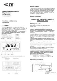
Analogue Output 1 Reading Bottom (Parameter154), the lower limit of the parameter value that will beoutput. This value can range between Parameter Minimum and Parameter Maximum.Analogue Output 1 Output Top (Parameter155), the analogue output level that will be achieved whenthe parameter reading reaches Reading Top. The value of output top will be greater than Output Bottomand Less than or equal to Analogue Hardware Maximum.Analogue Output 1 Output Bottom (Parameter156), the analogue output level that will be achievedwhen the parameter reading reaches Reading Bottom. The value of Output Bottom will be greater than orequal to Analogue Hardware Minimum and Less than Output Top.Analogue Output 2 Output Parameter (Parameter160), the number of the input parameter that is to beoutput on analogue output 2. A value of zero signifies the analogue output is unused.Analogue Output 2 Parameter Maximum (Parameter161), the maximum value that the selected inputparameter can reach.Analogue Output 2 Parameter Minimum (Parameter162), the minimum value that the selected inputparameter can reach.Analogue Output 2 Reading Top (Parameter163), the upper limit of the parameter value that will beoutput. This value can range between Parameter Minimum and Parameter Maximum.Analogue Output 2 Reading Bottom (Parameter164), the lower limit of the parameter value that will beoutput. This value can range between Parameter Minimum and Parameter Maximum.Analogue Output 2 Output Top (Parameter165), the analogue output level that will be achieved whenthe parameter reading reaches Reading Top. The value of output top will be greater than Output Bottomand Less than or equal to Analogue Hardware Maximum.Analogue Output 2 Output Bottom (Parameter166), the analogue output level that will be achievedwhen the parameter reading reaches Reading Bottom. The value of Output Bottom will be greater than orequal to Analogue Hardware Minimum and Less than Output Top.Analogue Output OperationDepending on the settings for output top, output bottom, reading top and reading bottom, the analogueoutput can be configured to operate in a number of modes.Normal Mode – As the reading value increases between the user set values for reading top and readingbottom the output also increases in magnitude between output top and bottom. As the reading valuedecreases between reading top and reading bottom, the output also decreases.OutputValueReading ValuePage 23 of 35 <strong>RS485</strong> <strong>Guide</strong> 07/02 Rev 6
Constant Current Mode - the values for output top and bottom are set to the same magnitude (thedesired output level). The setting of reading top and bottom has no effect.OutputValueReadingValueRegardless of the prevailing reading the analogue output will remain at the same levelSetting the Analogue Operating ModeThe following table illustrates how the various operating modes can be configured by setting therelationship between the values of output top & output bottom and reading top & reading bottom.Output Limits Reading Limits ModeBottom < Top Bottom < Top NormalBottom < Top Top < Bottom ReverseTop < Bottom Bottom < Top ReverseTop < Bottom Top < Bottom NormalBottom < Top Bottom = Top Normal ThresholdTop < Bottom Bottom = Top Reverse ThresholdIn each case, the values of the output limits must be between Output Min. and Output Max. and the valuesof reading limits must be between Reading Min. and Reading Max.Holding Register specific to the SPRRelay Number (Parameter 30) The relay number associated with the relay configuration parameters thatfollow. Writing a relay number in the range 1 to 16 to this register updates the relay configurationparameters to reflect the settings for that relay.Page 25 of 35 <strong>RS485</strong> <strong>Guide</strong> 07/02 Rev 6
Trip Function (Parameter 31) The trip function the relay given by parameter 30 is currently performing.This is an enumerated type that determines the trip function.Number Function0 Undefined1 Over Voltage (ANSI 59)2 Under Voltage (ANSI 27)3 Over Frequency (ANSI 81O)4 Under Frequency (ANSI 81U)5 Reverse Power (ANSI 32R)6 Phase Unbalance Voltage (ANSI 47)7 Time Over current with Voltage Restraint (ANSI 51V)8 Time Over current (ANSI 51)9 Ground Fault (ANSI 51G)10 Synchronising Check (ANSI 25)11 Synch Check with Dead Bus (ANSI 25)12 Phase Sequence (ANSI 47)13 Logical AND14 Logical OR15 Logical NAND16 Logical NOR17 Logical XOR18 Logical Vote19 Logical Disc20 Alarm21 Unacknowledged AlarmTrip Mode (Parameter 32) This is a bit set, returned as a floating-point number it has the following values,which may be added for composites functions. The setting is binary weighted, e.g. A register setting of 3indicates inverted and alarm functions are enabled (1 + 2 = 3).Function ValueInverted 1Alarm 2Latched 4Logged 8Trip Status (Parameter 33) This is a bit set, returned as a floating point number and has the functionsshown below.Name Description Value AccessCurrentState The current state of the trip condition 1 RActive The current state of the latch ( if set ) 2 RAcked Acknowledged alarm 4 R/WInAlarm The trip is in alarm 8 RClearLatch Set to clear the latch 16 WPage 26 of 35 <strong>RS485</strong> <strong>Guide</strong> 07/02 Rev 6
Trip Parameter 1-6 (Parameter 34 to 39) These are the other parameters for the trip. The function ofthese is dependent on the trip type, and relates directly to the menu layout through the front panel.Trip Name P 1 P 2 P 3 P 4 P 5 P 6Over Volts 59 TripPointDifferential TimeDelayUnder Volts 27 TripPointDifferential TimeDelayOver Freq.81OTripPointDifferential TimeDelayUnder Freq.81UTripPointDifferential TimeDelayReverse Pwr32RTripPointDifferential TimeDelayUnBal Volts 47 TripPointDifferential TimeDelayI/T+V.R. 51V Trip Nominal Time Time DialPoint Volts CurveI/T 51 Trip Time Time DialPoint CurveGround Fault Trip Time Dial51GPointSync 25 Phase Voltage Voltage Time Slip Freq.Angle Delta Min. DelaySync+DB 25 Phase Voltage Voltage Deadbus Time Delay Slip Freq.Angle Delta Min.Phase Order47TimeDelayLogical AND Input 1 Input 2 Input 3 Delay On Delay OffLogical OR Input 1 Input 2 Input 3 Delay On Delay OffLogical NAND Input 1 Input 2 Input 3 Delay On Delay OffLogical NOR Input 1 Input 2 Input 3 Delay On Delay OffLogical XOR Input 1 Input 2 Input 3 Delay On Delay OffLogical Vote Input 1 Input 2 Input 3 Delay On Delay OffLogical Disc Input 1 Input 2 Input 3 Delay On Delay OffAlarmTimeDelayUnack Alarm TimeDelayPage 27 of 35 <strong>RS485</strong> <strong>Guide</strong> 07/02 Rev 6
Appendix A: Instrument Input RegistersIn the table the “System Configuration” is defined by the number of wires, 4 represents a 3 phase 4 wire system, 3 represents a 3 phase3 wire system and 2 represents a single phase system. A dot (•) in the system configuration column indicates that the parameter is validfor that wiring system, a dash (-) will return the value zero.ParameterNo<strong>Modbus</strong> StartAddressParameter Integra 2000Configuration (Noof Wires)Integra 1000Configuration (Noof Wires)Integra 1540Configuration (Noof Wires)Integra 1560/80Configuration (No ofWires)1p3w 2wSPR Configuration(No of Wires)HighByteLowByte4 3 2 4 3 2 4 3 2 4 3 1p4 3 21 00 00 Volts 1 • • • • • • • • - • • • • • • -2 00 02 Volts 2 • • - • • - • • - • • • - • • -3 00 04 Volts 3 • • - • • - • • - • • - - • • -4 00 06 Current 1 • • • • • • • • - • • • • • • -5 00 08 Current 2 • • - • • - • • - • • • - • • -6 00 0A Current 3 • • - • • - • • - • • - - • • -7 00 0C Watts 1 • - • - - - • - - • - • • • - -8 00 0E Watts 2 • - - - - - • - - • - • - • - -9 00 10 Watts 3 • - - - - - • - - • - - - • - -10 00 12 VA 1 • - • - - - • - - • - • • • - -11 00 14 VA 2 • - - - - - • - - • - • - • - -12 00 16 VA 3 • - - - - - • - - • - - - • - -13 00 18 VAr 1 • - • - - - • - - • - • • • - -14 00 1A VAr 2 • - - - - - • - - • - • - • - -15 00 1C VAr 3 • - - - - - • - - • - - - • - -16 00 1E Power Factor 1 • - • - - - • - - • - • • • - -17 00 20 Power Factor 2 • - - - - - • - - • - • - • - -18 00 22 Power Factor 3 • - - - - - • - - • - - - • - -19 00 24 Phase Angle 1 • - • - - - • - - • - • • • - -20 00 26 Phase Angle 2 • - - - - - • - - • - • - • - -21 00 28 Phase Angle 3 • - - - - - • - - • - - - • - -Page 29 of 35 <strong>RS485</strong> <strong>Guide</strong> 07/02 Rev 6
ParameterNo<strong>Modbus</strong> StartAddressParameter Integra 2000Configuration (Noof Wires)Integra 1000Configuration (Noof Wires)Integra 1540Configuration (Noof Wires)Integra 1560/80Configuration (No ofWires)1p3w 2wSPR Configuration(No of Wires)HighByteLowByte4 3 2 4 3 2 4 3 2 4 3 1p4 3 222 00 2A Volts Ave • • • • • • • - - • • • • • - -23 00 2C Voltage Sum - - - - - - - - - - - - - - - -24 00 2E Current Ave • • • • • • • - - • • • • • • -25 00 30 Current Sum • • • - - - • - - • • • • • • -26 00 32 Watts Ave - - - - - - - - - - - - - - - -27 00 34 Watts Sum • • • • • • • • - • • • • • • -28 00 36 VA Ave - - - - - - - - - - - - - - - -29 00 38 VA Sum • • • • • • • • - • • • • • • -30 00 3A VAr Ave - - - - - - - - - - - - - - - -31 00 3C VAr Sum • • • • • • • • - • • • • • • -32 00 3E Power Factor Ave • • • • • • • • - • • • • - - -33 00 40 Power Factor Sum - - - - - - - - - - - - - - - -34 00 42 Phase Angle Ave • • • - - - • • - • • • • - - -35 00 44 Phase Angle Sum - - - - - - - - - - - - - - - -36 00 46 Frequency • • • • • • • • - • • • • • • -37 00 48 W.hr Import • • • • • • • • - • • • • - - -38 00 4A W.hr Export • • • - - - - - - - - - - - - -39 00 4C VAr.h Import • • • • • • • • - • • - • - - -40 00 4E VAr.h Export • • • - - - - - - - - - - - - -41 00 50 VA.h • • • - - - - - - - - - - - - -42 00 52 A.h • • • - - - - - - - - - - - - -43 00 54 W Demand Import • • • • • • • • - • • • • - - -44 00 56 W Max. Demand Import • • • • • • • • - • • • • - - -45 00 58 W Demand Export • • • - - - - - - - - - - - - -46 00 5A W Max. Demand Export • • • - - - - - - - - - - - - -47 00 5C VAr Demand Import • • • - - - - - - - - - - - - -48 00 5E VAr Max Demand Import • • • - - - - - - - - - - - - -49 00 60 VAr Demand Export • • • - - - - - - - - - - - - -50 00 62 VAr Max Demand Export • • • - - - - - - - - - - - - -51 00 64 VA Demand • • • - - - - - - - - - - - - -52 00 66 VA Max. Demand • • • - - - - - - - - - - - - -Page 30 of 35 <strong>RS485</strong> <strong>Guide</strong> 07/02 Rev 6
ParameterNo<strong>Modbus</strong> StartAddressParameter Integra 2000Configuration (Noof Wires)Integra 1000Configuration (Noof Wires)Integra 1540Configuration (Noof Wires)Integra 1560/80Configuration (No ofWires)1p3w 2wSPR Configuration(No of Wires)HighByteLowByte4 3 2 4 3 2 4 3 2 4 3 1p4 3 253 00 68 A Demand • • • • • • • • - • • • • - - -54 00 6A A Max. Demand • • • • • • • • - • • • • - - -55 00 6C Volts 1 Max. • • • - - - - - - - - - - - - -56 00 6E Volts 1 Min. • • • - - - - - - - - - - - - -57 00 70 Volts 2 Max. • • - - - - - - - - - - - - - -58 00 72 Volts 2 Min. • • - - - - - - - - - - - - - -59 00 74 Volts 3 Max. • • - - - - - - - - - - - - - -60 00 76 Volts 3 Min. • • - - - - - - - - - - - - - -61 00 78 Current 1 Max. • • • - - - - - - - - - - - - -62 00 7A Current 1 Min. • • • - - - - - - - - - - - - -63 00 7C Current 2 Max. • • - - - - - - - - - - - - - -64 00 7E Current 2 Min. • • - - - - - - - - - - - - - -65 00 80 Current 3 Max. • • - - - - - - - - - - - - - -66 00 82 Current 3 Min. • • - - - - - - - - - - - - - -67 00 84 Volts Average Max. • • • - - - - - - - - - - - - -68 00 86 Volts Average Min. • • • - - - - - - - - - - - - -69 00 88 Volts Sum Max. - - - - - - - - - - - - - - - -70 00 8A Volts Sum Min. - - - - - - - - - - - - - - - -71 00 8C Current Ave Max. - - - - - - - - - - - - - - - -72 00 8E Current Ave Min. - - - - - - - - - - - - - - - -73 00 90 Current Sum Max. • • • - - - - - - - - - - - - -74 00 92 Current Sum Min. • • • - - - - - - - - - - - - -75 00 94 Watt 1 Max. • - • - - - - - - - - - - - - -76 00 96 Watt 1 Min. • - • - - - - - - - - - - - - -77 00 98 Watt 2 Max. • - - - - - - - - - - - - - - -78 00 9A Watt 2 Min. • - - - - - - - - - - - - - - -79 00 9C Watt 3 Max. • - - - - - - - - - - - - - - -80 00 9E Watt 3 Min. • - - - - - - - - - - - - - - -81 00 A0 Watt Sum Max. • • • - - - - - - - - - - - - -82 00 A2 Watt Sum Min. • • • - - - - - - - - - - - - -83 00 A4 VAr 1 Max. • - • - - - - - - - - - - - - -Page 31 of 35 <strong>RS485</strong> <strong>Guide</strong> 07/02 Rev 6
ParameterNo<strong>Modbus</strong> StartAddressParameter Integra 2000Configuration (Noof Wires)Integra 1000Configuration (Noof Wires)Integra 1540Configuration (Noof Wires)Integra 1560/80Configuration (No ofWires)1p3w 2wSPR Configuration(No of Wires)HighByteLowByte4 3 2 4 3 2 4 3 2 4 3 1p4 3 284 00 A6 VAr 1 Min. • - • - - - - - - - - - - - - -85 00 A8 VAr 2 Max. • - - - - - - - - - - - - - - -86 00 AA VAr 2 Min. • - - - - - - - - - - - - - - -87 00 AC VAr 3 Max. • - - - - - - - - - - - - - - -88 00 AE VAr 3 Min. • - - - - - - - - - - - - - - -89 00 B0 VAr Sum Max. • • • - - - - - - - - - - - - -90 00 B2 VAr Sum Min. • • • - - - - - - - - - - - - -91 00 B4 VA1 Max. • - • - - - - - - - - - - - - -92 00 B6 VA 1 Min. • - • - - - - - - - - - - - - -93 00 B8 VA 2 Max. • - - - - - - - - - - - - - - -94 00 BA VA 2 Min. • - - - - - - - - - - - - - - -95 00 BC VA3 Max. • - - - - - - - - - - - - - - -96 00 BE VA3 Min. • - - - - - - - - - - - - - - -97 00 C0 VA Sum Max. • • • - - - - - - - - - - - - -98 00 C2 VA Sum Min. • • • - - - - - - - - - - - - -99 00 C4 Frequency Max. • • • - - - - - - - - - - - - -100 00 C6 Frequency Min. • • • - - - - - - - - - - - - -101 00 C8 V L1-L2 • - - • - - • - - • - • - • - -102 00 CA V L2-L3 • - - • - - • - - • - - - • - -103 00 CC V L3-L1 • - - • - - • - - • - - - • - -104 00 CE V L-L Ave • - - - - - • - - • - • - • - -105 00 D0 V L1-L2 Max • - - - - - - - - - - - - - - -106 00 D2 V L1-L2 Min • - - - - - - - - - - - - - - -107 00 D4 V L2-L3 Max • - - - - - - - - - - - - - - -108 00 D6 V L2-L3 Min • - - - - - - - - - - - - - - -109 00 D8 V L3-L1 Max • - - - - - - - - - - - - - - -110 00 DA V L3-L1Min • - - - - - - - - - - - - - - -111 00 DC V L-L Ave Max • - - - - - - - - - - - - - - -112 00 DE V L-L Ave Min • - - - - - - - - - - - - - - -113 00 E0 I Neutral • - - • - - • - - • - • - • - -114 00 E2 Bus Frequency - - - - - - - - - - - - - • • -Page 32 of 35 <strong>RS485</strong> <strong>Guide</strong> 07/02 Rev 6
ParameterNo<strong>Modbus</strong> StartAddressParameter Integra 2000Configuration (Noof Wires)Integra 1000Configuration (Noof Wires)Integra 1540Configuration (Noof Wires)Integra 1560/80Configuration (No ofWires)1p3w 2wSPR Configuration(No of Wires)HighByteLowByte4 3 2 4 3 2 4 3 2 4 3 1p4 3 2115 00 E4 Bus-Gen Phase Angle - - - - - - - - - - - - - • • -116 00 E6 Bus Volts - - - - - - - - - - - - - • • -117 00 E8 I Ground - - - - - - - - - - - - - • • -118 00 EA THD Volts 1 - - - - - - • • - • • • • - - -119 00 EC THD Volts 2 - - - - - - • • - • • • - - - -120 00 EE THD volts 3 - - - - - - • • - • • - - - - -121 00 F0 THD Current 1 - - - - - - • • - • • • • - - -122 00 F2 THD Current 2 - - - - - - • • - • • • - - - -123 00 F4 THD Current 3 - - - - - - • • - • • - - - - -125 00 F8 THD Voltage Mean - - - - - - • • - • • • • - - -126 00 FA THD Current Mean - - - - - - • • - • • • • - - -128 00 FE Power Factor (+Ind/ - Cap) - - - - - - - - - • • • • - - -400 03 1E Event: Log Number - - - - - - - - - - - - - • • -401 03 20 Event: Relay Number - - - - - - - - - - - - - • • -402 03 22 Event: Year - - - - - - - - - - - - - • • -403 03 24 Event: Month - - - - - - - - - - - - - • • -404 03 26 Event: Day - - - - - - - - - - - - - • • -405 03 28 Event: Hour - - - - - - - - - - - - - • • -406 03 2A Event: Minute - - - - - - - - - - - - - • • -407 03 2C Event: Second - - - - - - - - - - - - - • • -408 03 2E Event Log Increment - - - - - - - - - - - - - • • -Page 33 of 35 <strong>RS485</strong> <strong>Guide</strong> 07/02 Rev 6
Appendix B: Instrument Holding RegistersIn the table the “System Configuration” is defined by the number of wires, 4 represents a 3 phase 4 wire system, 3 represents a 3 phase3 wire system and 2 represents a single phase system. A dot (•) in the system configuration column indicates that the parameter is validfor that wiring system, a dash (-) will return the value zero.Parameter <strong>Modbus</strong> StartIntegra Integra Integra Integra SPRParameterNo Address2000 1000 1540 1560/80HighByteLowByte1 00 00 Demand Time • • • • -2 00 02 Demand Period • • • • -3 00 04 Demand Interval • • • • -4 00 06 System Volts • • • • •5 00 08 System Current • • • • •6 00 0A System Type • • • • •7 00 0C Relay Pulse Width • • • • -8 00 0E Energy Reset • • • • -12 00 16 Pulse Width Divisor • • • • -19 00 18 System Power - - • • -21 00 1A <strong>Modbus</strong> Word Order - - • • -30 00 3A Relay Number - - - - •31 00 3C Trip Function - - - - •32 00 3E Trip Mode - - - - •33 00 40 Trip Status - - - - •34 00 42 Trip 1 st Parameter - - - - •35 00 44 Trip 2 nd Parameter - - - - •36 00 46 Trip 3 rd Parameter - - - - •37 00 48 Trip 4 th Parameter - - - - •38 00 4A Trip 5 th Parameter - - - - •39 00 4C trip 6 th Parameter - - - - •50 00 62 Real-time clock: Year - - - - •51 00 64 Real-time clock: Month - - - - •52 00 66 Real-time clock: Day - - - - •Page 34 of 35 <strong>RS485</strong> <strong>Guide</strong> 07/02 Rev 6
Parameter <strong>Modbus</strong> StartIntegra Integra Integra Integra SPRParameterNo Address2000 1000 1540 1560/80HighByteLowByte53 00 68 Real-time clock: Hour - - - - •54 00 6A Real-time clock: Minute - - - - •55 00 6C Real-time clock: Second - - - - •150 01 2A Secondary Volts - - • • -152 01 2B Nominal Volts - - • • -155 01 34 *Analogue Hardware Max - - - • -156 01 36 *Analogue Hardware Min - - - • -157 01 38 *Analogue Output 1: Output Parameter - - - • -158 01 3A *Analogue Output 1: Parameter Max - - - • -159 01 3C *Analogue Output 1: Parameter Min - - - • -160 01 3E *Analogue Output 1: Reading Top - - - • -161 01 40 *Analogue Output 1: Reading Bottom - - - • -162 01 42 *Analogue Output 1: Output Top - - - • -165 01 48 *Analogue Output 1: Output Bottom - - - • -166 01 4A *Analogue Output 2: Output Parameter - - - • -167 01 4C *Analogue Output 2: Parameter Max - - - • -168 01 4E *Analogue Output 2: Parameter Min - - - • -169 01 50 *Analogue Output 2: Reading Top - - - • -170 01 52 *Analogue Output 2: Reading Bottom - - - • -171 01 54 *Analogue Output 2: Output Top - - - • -172 01 56 *Analogue Output 2: Output Bottom - - - • -* Requires Analogue Output option to be fitted.Page 35 of 35 <strong>RS485</strong> <strong>Guide</strong> 07/02 Rev 6