Cadence OrCAD Signal Explorer Datasheet
Cadence OrCAD Signal Explorer Datasheet
Cadence OrCAD Signal Explorer Datasheet

You also want an ePaper? Increase the reach of your titles
YUMPU automatically turns print PDFs into web optimized ePapers that Google loves.
<strong>Cadence</strong> <strong>OrCAD</strong> <strong>Signal</strong> <strong>Explorer</strong><br />
Pre- and post-route topology exploration and signal integrity analysis<br />
<strong>Cadence</strong> ® <strong>OrCAD</strong> ® <strong>Signal</strong> <strong>Explorer</strong> helps engineers address signal integrity issues throughout the<br />
design process from the conceptual schematic through placement and final routing. It enables<br />
pre- and post-route topology exploration, signal analysis, and validation, allowing designers to<br />
increase circuit reliability and drive known-good interconnect requirements throughout the PCB<br />
design flow.<br />
Increasing design density, complexity,<br />
and faster edge rates create a<br />
multitude of signal integrity issues,<br />
which can lead to time-consuming<br />
and frustrating simulate-fix-simulate<br />
iterations and increased production<br />
costs. <strong>Cadence</strong> <strong>OrCAD</strong> <strong>Signal</strong> <strong>Explorer</strong><br />
helps engineers address these issues<br />
throughout the design process—<br />
from the very beginning of the cycle<br />
through placement and final routing.<br />
The same signal integrity issues<br />
increase the need for an integrated<br />
design flow that enables designers to<br />
easily perform post-layout extraction<br />
and verification of complex PCB interconnect.<br />
An integrated design and<br />
analysis environment eliminates the<br />
need to translate design databases<br />
to run simulations and analysis.<br />
Seamless integration with <strong>Cadence</strong><br />
<strong>OrCAD</strong> PCB Editor eliminates database<br />
conversion and possible translation<br />
issues. Engineers can now perform<br />
signal integrity analysis or topology<br />
exploration at any stage of the design<br />
cycle—when the board is partially or<br />
fully placed, partially or fully routed,<br />
and even when no netlist or PCB<br />
database exists.<br />
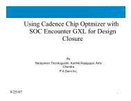
Figure 1: <strong>OrCAD</strong> <strong>Signal</strong> <strong>Explorer</strong> analyzes and validates topologies and interconnect to<br />
help minimize potential SI-related issues for fewer re-spins and shorter lab debug time<br />
<strong>OrCAD</strong> <strong>Signal</strong> <strong>Explorer</strong> consists of the<br />
Tlsim simulation engine, the SigXplorer<br />
topology editor, the SigWave waveform<br />
display, translators from other modeling<br />
formats, and a library model editing/<br />
management subsystem. The IBIS<br />
modeling standard is supported<br />
natively in addition to <strong>Cadence</strong> DML<br />
(device modeling language) support.<br />
A transistor-level model import wizard<br />
prepares models to run with the native<br />
SPICE simulators.
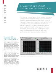
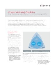
Figure 2: View and analyze simulation results in SigWave<br />
Benefits<br />
• Enables pre- and post-layout signal<br />
integrity analysis at any stage of the design<br />
cycle, ensuring constraint adherence<br />
• Allows exploration, analysis, and design of<br />
interconnect topologies to increase circuit<br />
reliability, improve circuit performance,<br />
and reduce prototype re-spins<br />
• Eliminates the need to translate design<br />
databases to run simulations by<br />
importing extracted topologies directly<br />
from <strong>OrCAD</strong> PCB Editor<br />
• Provides an easy-to-use model editing<br />
environment that creates, manipulates,<br />
and validates a variety of models, quickly<br />
improving model/simulation performance<br />
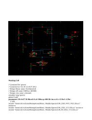
Figure 3: Users can change topologies or stack-up information and perform quick, iterative tradeoffs<br />
Features<br />
Analysis<br />
<strong>Cadence</strong> <strong>OrCAD</strong> <strong>Signal</strong> <strong>Explorer</strong><br />
<strong>OrCAD</strong> <strong>Signal</strong> <strong>Explorer</strong> provides pre- and<br />
post-route topology exploration and transmission<br />
line analysis. It allows conceptual,<br />
pre-design / schematic topology exploration<br />
and simulation as well as routed or<br />
unrouted board topology extraction and<br />
analysis directly from an <strong>OrCAD</strong> PCB Editor<br />
database (.brd).<br />
Pre-layout analysis<br />
Through topology exploration and<br />
simulation, critical nets can be planned<br />
proactively to minimize signal integrity<br />
problems earlier in the design cycle. Using<br />
the SigXplorer canvas, topologies are easily<br />
defined along with board stack-up requirements<br />
and signal termination strategies.<br />
Post-layout analysis<br />
With the ability to extract topologies<br />
directly from the PCB design database,<br />
simulation on critical nets allows detailed<br />
analysis to validate the layout work<br />
matches the pre-route requirements.<br />
<strong>Signal</strong>s are extracted back into the same<br />
canvas that was used to analyze the net,<br />
during pre-route, and the routed signal’s<br />
analysis can be compared to the expected<br />
results. If the results do not match, the<br />
routed board can be modified and the<br />
net re-analyzed.<br />
SigXplorer module<br />
<strong>OrCAD</strong> <strong>Signal</strong> <strong>Explorer</strong> provides an<br />
electrical view of the physical interconnect<br />
and a simulation cockpit for analysis of<br />
critical high-speed signals. Users can<br />
explore a net before schematics are<br />
created by using the SigXplorer module in<br />
a standalone mode. SigXplorer provides<br />
various stripline and microstrip models—<br />
lossy or lossless—to get started with the<br />
exploration. Since <strong>OrCAD</strong> <strong>Signal</strong> <strong>Explorer</strong><br />
integrates seamlessly with <strong>OrCAD</strong> PCB<br />
Editor, users can extract a net in the<br />
pre-route or post-route stage right into<br />
SigXplorer. Users can then quickly analyze<br />
the signal using SPICE-based simulation.<br />
www.cadence.com 2
SigWave<br />
The SigWave waveform display can<br />
present simulation results in multiple<br />
formats. The oscilloscope mode allows the<br />
display of individual waveforms on and<br />
off, and provides markers for on-screen<br />
measurement. The logic analyzer mode<br />
presents waveforms alongside one<br />
another, so logic behavior and bus<br />
transactions are easier to observe. The<br />
spectrum analyzer mode displays signal<br />
behavior in the frequency domain using<br />
one of several FFT techniques. The<br />
eye-diagram mode is useful for viewing<br />
patterns in long simulation sequences.<br />
SigWave also allows import of waveform<br />
data directly from various standard test<br />
equipment formats as well as from the<br />
output formats of popular signal integrity<br />
analysis tools.<br />
Model integrity<br />
The Model Integrity module provides<br />
an editing environment within <strong>OrCAD</strong><br />
<strong>Signal</strong> <strong>Explorer</strong> that allows the creation,<br />
manipulation, and validation of models<br />
quickly and easily. This module includes<br />
a model browser and syntax checker<br />
for models written in IBIS as well as for<br />
advanced models written in DML.<br />
<strong>OrCAD</strong> <strong>Signal</strong> <strong>Explorer</strong> accepts device<br />
models from a variety of digital modeling<br />
formats—including support for the<br />
IBIS modeling standard—which means<br />
models created by most semiconductor<br />
manufacturers can be used. In addition,<br />
<strong>OrCAD</strong> <strong>Signal</strong> <strong>Explorer</strong> provides DML,<br />
a next-generation modeling language<br />
for more complex devices. This flexible<br />
macromodeling extension language<br />
augments IBIS and allows state-of-the-art<br />
I/O functionality to be modeled quickly<br />
and accurately.<br />
Simulation environment<br />
The Tlsim simulation engine combines<br />
the advantages of traditional SPICEbased<br />
structural modeling with the speed<br />
of behavioral analysis. It includes an<br />
IBIS-style behavioral driver element that<br />
models I/O behavior based on the V-I<br />
and V-T data provided by behavioral<br />
modeling techniques.<br />
By combining both structural and<br />
behavioral modeling techniques,<br />
Tlsim enables accurate and efficient<br />
modeling of complex device behavior. It<br />
includes a lossy, frequency-dependent<br />
transmission-line model that accurately<br />
predicts the distributed behavior of<br />
PCB traces up to several gigahertz.<br />
An integrated electrical field solver<br />
determines the electrical characteristics of<br />
routed etch and creates electrical models<br />
of PCB vias.<br />
Future-Proof Scalability<br />
Unlike other signal integrity solutions,<br />
<strong>OrCAD</strong> <strong>Signal</strong> <strong>Explorer</strong> has the ability<br />
to grow with changing exploration and<br />
analysis needs and technology challenges.<br />
Based on Allegro ® SI technology, the<br />
<strong>OrCAD</strong> SI solution provides the security<br />
of scalability to meet future challenges<br />
easily. Features and technologies are<br />
shared across the <strong>OrCAD</strong> and Allegro<br />
product lines. This allows products<br />
to be easily upgraded and expanded<br />
without the need to translate databases<br />
or libraries, learn new applications, or<br />
change use models.<br />
<strong>Cadence</strong> <strong>OrCAD</strong> <strong>Signal</strong> <strong>Explorer</strong><br />
Sales, Technical Support, and<br />
Training<br />
The <strong>OrCAD</strong> product line is owned by<br />
<strong>Cadence</strong> Design Systems, Inc., and<br />
supported by a worldwide network of<br />
<strong>Cadence</strong> Channel Partners (VARs).<br />
For sales, technical support, or training,<br />
contact your local <strong>Cadence</strong> Channel<br />
Partner (VAR). For a complete list of<br />
authorized <strong>Cadence</strong> Channel Partners<br />
(VARs), visit<br />
www.cadence.com/Alliances/<br />
channel_partner<br />
<strong>Cadence</strong> is transforming the global electronics industry through a vision called EDA360.<br />
With an application-driven approach to design, our software, hardware, IP, and services help<br />
customers realize silicon, SoCs, and complete systems efficiently and profitably. www.cadence.com<br />
© 2011 <strong>Cadence</strong> Design Systems, Inc. All rights reserved. <strong>Cadence</strong>, the <strong>Cadence</strong> logo, Allegro, and <strong>OrCAD</strong> are registered trademarks of <strong>Cadence</strong><br />
Design Systems, Inc. All others are properties of their respective holders.<br />
21574 11/11 MK/DM/PDF