Auxiliary M-Contactor Kit for FlexPak Plus and MinPak Plus DC Drives
Auxiliary M-Contactor Kit for FlexPak Plus and MinPak Plus DC Drives
Auxiliary M-Contactor Kit for FlexPak Plus and MinPak Plus DC Drives

You also want an ePaper? Increase the reach of your titles
YUMPU automatically turns print PDFs into web optimized ePapers that Google loves.
<strong>Auxiliary</strong> M-<strong>Contactor</strong> <strong>Kit</strong><strong>for</strong> <strong>FlexPak</strong> <strong>Plus</strong> <strong>and</strong> <strong>MinPak</strong> <strong>Plus</strong> <strong>DC</strong> <strong>Drives</strong>Model Number 14C219Instruction Manual D2-3383!ATTENTION: Only qualified electrical personnel familiar with the construction <strong>and</strong> operation ofthis equipment <strong>and</strong> the hazards involved should install, adjust, operate, <strong>and</strong>/or service thisequipment. Read <strong>and</strong> underst<strong>and</strong> this manual <strong>and</strong> other applicable manuals in their entiretybe<strong>for</strong>e proceeding. Failure to observe this precaution could result in severe bodily injury or lossof life.ATTENTION: The <strong>Auxiliary</strong> M-contactor kit contains static-sensitive components. Do not touchthe components or connectors on the printed circuit board. When not installed, the contents ofthe kit should be stored in an anti-static bag. Failure to observe this precaution could result indamage to, or destruction of, the equipment.Product DescriptionThe <strong>Auxiliary</strong> M-contactor allows you to interlock the on/off status of a single-phase <strong>FlexPak</strong> <strong>Plus</strong> or<strong>MinPak</strong> <strong>Plus</strong> <strong>DC</strong> drive with user-supplied devices. The <strong>Auxiliary</strong> M-contactor provides a single pair of Form Ccontacts, one normally open (NO) <strong>and</strong> one normally closed (NC). Both contacts share a common terminal, asshown in figure 1. The contacts function <strong>for</strong> unidirectional or bi-directional (<strong>for</strong>ward/reverse) drives.Typical applications include pilot <strong>and</strong> indicator lights, alarms, <strong>and</strong> interlocks with other control circuitsdependent on the drive system. The user must provide wiring to external devices. Wire size depends upon theapplication, but should not exceed AWG 14. See the device instruction manuals <strong>for</strong> further in<strong>for</strong>mation.The maximum rating of each contact is 1 A at 30 V<strong>DC</strong> (resistive) or 0.5 A at 120 VAC (resistive). Do not usethese contacts to control brakes or other power loads.The <strong>Auxiliary</strong> M-contactor is a printed circuit board with a contactor, a terminal strip, <strong>and</strong> an attached wireharness. It is designed to be mounted on the drive’s auxiliary mounting bracket. For 1/4 to 1-1/2 HP <strong>MinPak</strong><strong>Plus</strong> drives, the <strong>Auxiliary</strong> Mounting Bracket (M/N 14C209) must be ordered separately. The contents of the<strong>Auxiliary</strong> M-contactor kit are listed in table 1.Table 1 – Contents of the <strong>Auxiliary</strong> M-contactor <strong>Kit</strong>Description Quantity Part Number<strong>Auxiliary</strong> M-contactor 1 0-54379-1BInstruction Manual 1 D2-3383Reliance <strong>and</strong> <strong>MinPak</strong> are trademarks of Rockwell Automation.© 1998 Rockwell International Corporation
Installing the <strong>Auxiliary</strong> M-<strong>Contactor</strong>!ATTENTION: Do not install modification kits with power applied to the drive. Disconnect, lockout, <strong>and</strong> tag all sources of incoming AC power to the drive be<strong>for</strong>e attempting such installation.Verify that no voltage is present at the drive’s AC input terminals, L1 <strong>and</strong> L2. Failure to observethis precaution could result in severe bodily injury or loss of life.ATTENTION: The user is responsible <strong>for</strong> con<strong>for</strong>ming with all applicable local, national, <strong>and</strong>international codes. Failure to observe this precaution could result in damage to, or destructionof, the equipment.ATTENTION: This kit contains ESD (Electrostatic Discharge) sensitive parts <strong>and</strong> assemblies.Static control precautions are required when installing, testing, servicing, or repairing thisassembly. Failure to observe these precautions could result in damage to, or destruction of, theequipment.Refer to figure 1 <strong>and</strong> to your drive instruction manual <strong>for</strong> help locating <strong>and</strong> identifying drive components. Toinstall the <strong>Auxiliary</strong> M-contactor in your <strong>FlexPak</strong> <strong>Plus</strong> or <strong>MinPak</strong> <strong>Plus</strong> <strong>DC</strong> drive:Step 1.Step 2.Step 3.Step 4.Step 5.Step 6.Step 7.Step 8.Step 9.Disconnect, lock out, <strong>and</strong> tag input power to the drive.Remove the drive cover <strong>and</strong> verify that no voltage is present at the drive’s AC input terminals,L1 <strong>and</strong> L2.For 1/4 to 1-1/2 HP <strong>MinPak</strong> <strong>Plus</strong> drives: Install the <strong>Auxiliary</strong> Mounting Bracket, as described ininstruction manual D2-3379.Position the <strong>Auxiliary</strong> M-contactor in the center of the <strong>Auxiliary</strong> Mounting Bracket with the wireharness on the left. When the <strong>Auxiliary</strong> M-contactor is properly positioned, snap it into place in thebracket.Connect the <strong>Auxiliary</strong> M-contactor’s three-wire harness connector to the three bayonet pins labeled“AUX. M.” near the upper left corner of the drive’s Regulator board. The yellow wire (39) is connectedto the pin marked “YEL.”Route the wires from the external devices into the drive chassis <strong>and</strong> connect them to the <strong>Auxiliary</strong>M-contactor’s terminal strip. Refer to figure 1 <strong>for</strong> terminal identification. To prevent shorts at exposedpoints, do not strip more than 6 mm (1/4 inch) of insulation from the wires.Verify the wiring of the <strong>Auxiliary</strong> M-contactor <strong>and</strong> ensure that all connections are securely fastened.Reattach the cover to the drive.Apply power <strong>and</strong> test the operation of the drive.This completes the installation of the <strong>Auxiliary</strong> M-contactor.2 <strong>Auxiliary</strong> M-<strong>Contactor</strong> <strong>Kit</strong> <strong>for</strong> <strong>FlexPak</strong> <strong>Plus</strong> <strong>and</strong> <strong>MinPak</strong> <strong>Plus</strong> <strong>DC</strong> <strong>Drives</strong>
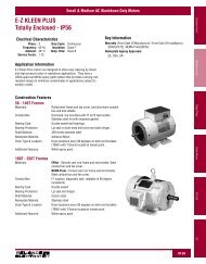
41 COM43 42 41NO NC COMTerminal Strip43 42Figure 1 – <strong>Auxiliary</strong> M-contactor Terminal Connections<strong>Auxiliary</strong> M-<strong>Contactor</strong> <strong>Kit</strong> <strong>for</strong> <strong>FlexPak</strong> <strong>Plus</strong> <strong>and</strong> <strong>MinPak</strong> <strong>Plus</strong> <strong>DC</strong> <strong>Drives</strong> 3
Publication D2-3383 November 1998 © 1998 Rockwell International Corporation. All rights reserved. Printed in USA.