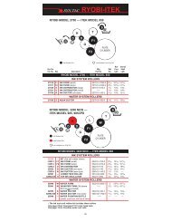
Ryobi 3302 5-roll Altra - ArdensParts.com
Ryobi 3302 5-roll Altra - ArdensParts.com
Ryobi 3302 5-roll Altra - ArdensParts.com

Create successful ePaper yourself
Turn your PDF publications into a flip-book with our unique Google optimized e-Paper software.
GENERAL INFORMATIONBASICCONFIGURATIONOF CRESTLINE ®ALTRA TM SERIESB 5/32" (4mm)A 5/32" (4mm)IMC 3/16" (5mm)POD 5/32" (4mm)FE 5/32" (4mm)AdjustmentsA. Intermediate to OscillatorB. Metering to IntermediateC. Metering to PanD. Oscillator to FormE. Form to PlatePlateCylinderRoller DescriptionP = PanM = MeteringI = IntermediateO = OscillatorF = FormTERMINOLOGYOPS = Operator's SideNOPS = Non Operator's SideTECHNICALASSISTANCEFor technical assistance during the installation, please contact:ACCEL GRAPHIC SYSTEMS11103 Indian TrailDallas, TX 75229PHONE (972) 484-6808FAX (800) 365-6510E-MAIL accel@dallas.netWEB SITE www.accelgraphicsystems.<strong>com</strong>Crestline ® <strong>Altra</strong> TM Series is covered by U.S. Patents Pending3
GENERAL INFORMATIONREQUIRED TOOLS1. Phillips Screwdriver2. Standard Screwdriver3. 1/8" & 3/32" Allen4. 2.5, 3, 4, 5, & 6 mm Allens5. 8, 10, 13, & 17 mm Wrenches6. 7/16" Open End Wrench7. Vise Grips8. 4 mm Punch9. Brass Drift10. 1/8" Punch11. Hammer4
DISASSEMBLY1Disconnect the press from the power supply. Remove inker guardson both printing units. Remove operating handles and upper sidecovers from OPS & NOPS sides of both printing heads. Remove thesmall covers over the water control mechanism OPS & NOPS. Onolder model presses, remove the gray plate that indicates the clicksin ratchet system. Remove the water tray and cloth covered <strong>roll</strong>ersfrom both printing units.2At the OPS, remove "E" clips and washers (subject arrows) fromstud and pull off the assembly held by these parts.3At the OPS, remove the spring behind the arm (large subject arrow,not visible in picture). Remove the "E" clips and washers (subjectarrows) and pull the assembly off.7
DISASSEMBLY4At the OPS, remove the spring (#1), housing with clutch (#2), andinfinite water control (#3, held on by 4 bolts) from the end of thewater fountain <strong>roll</strong>er shaft. (Older models have an arm and ratchetassembly with a gear. Remove these pieces if the press does nothave the infinite water control. The gear has a set screw in it thatneeds to be loosened before you can remove it.)5Drive the pin out of the arm (large subject arrow) and remove it.Remove all the screws indicated by the subject arrows. The arrowson the left indicate the housings for the metal <strong>roll</strong>ers and ductor. Theupper arrow, on the right, is the water pan block. These are at theOPS.6Remove the bolt from the wiper bar (upper subject arrow). Theseare located at the OPS. (On older models, the bolt holding the wiperbar is at the NOPS.) Remove the wiper bar.OPTION: You can remove the small screw and clicker plate from thewater form adjustment screw block (lower subject arrow) andreplace it with the set screws #05-153025 provided by Accel. Thiswill secure the form to plate setting once adjusted.NOTE: This picture has the parts already removed.9
DISASSEMBLY7Unhook the wires from the solenoid at NOPS (subject arrow) andremove the it from the press. 3 screws hold the solenoid. Eachscrew has a washer and a spacer. Be sure these parts do not fallin the press.8At the NOPS, drive the pin out and remove the arm (subject arrowat far right.) Remove the screws near the other subject arrows9Remove the nut and spool from the end of the oscillator (subjectarrow.) The easiest way to do this is:1. Rotate the press, by hand, until the oscillator has moved all theway to the NOPS.2. Remove the nut and lock washer from the end of the oscillator.Save for reinstallation.3. Remove the oscillator bushing at the OPS and slide theoscillator <strong>roll</strong>er by hand to the OPS. The spool will <strong>com</strong>e off.Save all of the parts for reinstallation.11
DISASSEMBLY10Inspect cam follower for wear. If there is a substantial amount ofwear, it should be replaced before installation of new oscillator<strong>roll</strong>er.11Remove the cap screw (subject arrow) holding the two pieces of thewater fountain <strong>roll</strong>er together. Remove the bushings from the sideframe holding the <strong>roll</strong>er, slide the two pieces apart, and remove thepan <strong>roll</strong>er and extension from the press.NOTE: Older models may have a single piece fountain <strong>roll</strong>er.12Remove the 2 screws and bushing (subject arrow) for the oscillatorat the NOPS. Save for reinstallation. Slide the oscillator <strong>roll</strong>er out ofthe press.13
DISASSEMBLY13The water ductor mechanism (subject arrow) has a series of setscrews holding it to the shaft. Loosen all the set screws, includingthe one in the brass collar in the middle. Remove the bushingsholding the shaft in the side frames. Gently tap the shaft towards theOPS until it clears the inside of the press frame. The entireassembly can be removed.14Remove the bolt and spring loaded arm (subject arrow) at OPS &NOPS.15Remove the studs (subject arrow ) from inside the press frame.YOU ARE NOW READY TO INSTALL CRESTLINE ® ALTRA TMSERIES15
INSTALLATION1Install the new form oscillator <strong>roll</strong>er (X07-0431) provided by Accel.The easiest way to ac<strong>com</strong>plish this is by following this order:1. Place the <strong>roll</strong>er in position with the gear on the NOPS.2. Install the NOPS bushing that was previously removed.3. Hold spool in position and slide the shaft all the way through thespool.4. Install the OPS bushing assembly.5. Install the jam nut and lock washer on the NOPS end of theoscillator shaft and fully tighten.2Install the stripe adjustment blocks (X10-36 & X10-35) provided.These have an OPS & NOPS side. When installed, it needs to bepositioned so that the flat surface is facing up and level.3Install OPS & NOPS mounting plate. Use the large spools (X12-28)and cap head bolts & washers (X05-114138 & 05-313328) provided.On OPS, if there is a notched out cavity (large subject arrow)then use the spool (X12-27) with the flat portion facing towards thebottom. After mounting the spool use the second mounting bolt(X05-123113). Only one bolt is used per side.NOTE: Remove the caps from the mounting block after installation.The center adjustment bolt is pre-set at the factory andshould not need to be adjusted.17
INSTALLATION4Temporarily reconnect press to power supply. Make sure any looseparts or tools are clear for operation. Jog press and observe meshbetween the gear on the oscillator <strong>roll</strong>er and the mounting gear onthe NOPS mounting plate. A whining sound generally indicates thatthe gear mesh is too loose. A grinding sound indicates that the gearmesh is too tight. Adjust if necessary by loosening plate mountingbolts, repositioning and then retightening.5Install lift shaft (X15-18) into press with the longest portion thatextends past cams to the NOPS (left hand picture). At OPS &NOPS, install the lift shaft housings (X99-17) with the notchedportion aligned with the mounting hole (right hand picture). Use thecap head bolts (X05-127M12) and washers (X05-313442) providedto secure the housings to the frame.6At OPS & NOPS, slip the thin brass washer (X05-315630) and thenthe set collar (X13-5038) over the end of the lift shaft. Position shaftso that the end if flush with the set collar on OPS. Finger tighten onlyat this time.19
INSTALLATION7Place the dampener in the press as shown. The ball bearings on theend of the pan <strong>roll</strong>er shaft should sit in the notches of the mountingplates. Position the dampener evenly, side to side. Install the capsof the mounting brackets with the cap head bolts provided. Adjustnylon screws (X05-118M25P) on the side of the dampener frameuntil they contact the mounting plate without binding the dampenerand lock into position with the nylon nut (X05-218P).8Observe the position of the cams on the lift shaft. These camsshould line up with the ball bearings on the dampener and not touchthe dampener frames. If the cams are not centered then loosen theset collars and center. Fully tighten the set collars at this time.9Install the extension springs (X09-0102) on the OPS & NOPS. Itconnects on the spring stud on the dampener and the spring studon the stripe adjustment blocks installed in step #2.21
INSTALLATION10Slip the control block (X17-0303) over the end of the lift shaft (lefthand picture) but do not tighten the set screws at this time. With the2 button head screws (X05-134025) (upper subject arrow) justthreaded into the lower clamp block (X17-0108), slip the block overthe activation linkage (lower subject arrow). It is grooved to clampover the link (as shown). Push the lower clamp block down until itstops against the bend in the link and fully tighten the button headscrews.NOTE: Picture is shown with additional parts removed forviewing. It is not necessary to remove these parts in theinstallation.11Install the activation link (X17-0505) (upper subject arrow) providedby Accel. The link is mounted with a cap head bolt (05-173125) on top and bottom. However, the slotted portion (lowersubject arrow) of the link should be in the lower mounting hole.12Temporarily replace the single lever. Run the set screws on top ofthe dampener up until they no longer touch the blocks in the wateron position.23
INSTALLATION13With the single lever in the "WATER ON" position, rotate the lift shaftup until it contacts the lift cams on the dampener. Rotate the controlblock (upper subject arrow) clockwise so that the activation link(lower subject arrow) is topped out in the lower slot. Tighten the setscrews in the control block in this position making sure that it is flushwith the outside edge of the lift shaft.NOTE: When the linkage is set correctly, the dampener'sintermediate and oscillator <strong>roll</strong>ers will separate when thesingle lever is returned to the "OFF" position.14Install the new water form <strong>roll</strong>er (X07-0135) provided by Accel. Usethe original form <strong>roll</strong>er shaft. Check the end play of the <strong>roll</strong>er in thenight latch position and adjust if necessary.15Replace both of the inker guards with the new ones provided byAccel (X18-0132).YOU ARE NOW READY TO MAKE THE FINAL ADJUSTMENTS25
FINAL ADJUSTMENTS1INK UP THE DAMPENERMake sure the dampener is in the "OFF" position. Apply a smallamount of ink on the dampener oscillator <strong>roll</strong>er only. Turn on thepress and run for 30-40 seconds and allow the ink to mill. Only theoscillator and form <strong>roll</strong>er will ink up at this time.IOFMP2(4 mm)5/32"OSCILLATOR TO FORM ROLLER PRESSUREAfter the press sits still for 15-20 seconds, jog the press forwardslightly while looking at the form <strong>roll</strong>er. A stripe or bead line shouldappear on the form <strong>roll</strong>er which was created by the oscillator. Thisstripe should be 5/32" (4mm) wide. To adjust, turn the long slottedscrew (subject arrow) clockwise to increase the stripe at both OPS& NOPS. Refer to the <strong>Ryobi</strong> manual for this adjustment if necessaryas it is the same as the original dampener.PlateCylinderIOMP3FORM ROLLER TO PLATE CYLINDER PRESSUREDrop the dampener form <strong>roll</strong>er down to the plate and back to "OFF"again. This will leave a stripe on the plate which should be 5/32"(4mm). This stripe is adjusted exactly as the original dampener byturning the adjustment knobs. To increase pressure at both OPSand NOPS, turn the adjustment knobs counterclockwise.PlateCylinderF(4 mm)5/32"27
OPlateCylinderIFMP4(4 mm)5/32"FINAL ADJUSTMENTSINTERMEDIATE TO OSCILLATOR ROLLER PRESSURETemporarily remover the dampener metering <strong>roll</strong>er by removing thelower cap head bolts and remove the cap on the metering <strong>roll</strong>erretaining bracket. Drop the dampener down to the plate cylinderand back off. In addition to the form <strong>roll</strong>er contacting the plate, theintermediate <strong>roll</strong>er will drop down and contact the oscillator <strong>roll</strong>er.,Turn the intermediate <strong>roll</strong>er around by hand to reveal the stripewhich should be 5/32" (4mm). This pressure is adjusted by turningthe set screw on the dampener frame. Turning the set screws downwill decrease the stripe and vice versa. Tighten the lock nut after theproper stripe is obtained.OPlateCylinderIF5MP(3.5mm)METERING TO INTERMEDIATE PRESSUREReplace the dampener metering <strong>roll</strong>er and fully tighten the caphead bolt on the retaining bracket. Now you can ink up the entiredampener and run in the ink until it is smooth. The proper pressurebetween these <strong>roll</strong>ers is 3.5 mm. Adjustments are made by looseningthe lock nut on top of the metering <strong>roll</strong>er hanger and turning theset screw clockwise to increase the stripe and vice-versa. Tightenthe lock nut once the proper stripe is obtained.NOTE: In order to observe the stripe, it may be necessary toplace the single lever in the "WATER ON" position and jog thepress in reverse. You will then be able to observe the stripe onthe metering <strong>roll</strong>er.OPlateCylinderIFMP6(4.5 mm)3/16"MAXIMUM METERING TO PAN ROLLER PRESSURETurn the press on and run for 30-40 seconds to mill in the ink. Stopthe press and allow it to sit still for 15-20 seconds. Jog the pressforward and observe the stripe on the pan <strong>roll</strong>er. It should be 3/16"(4.5mm). Turn the knurled metering knobs clockwise to increasethe stripe and vice versa. When the proper stripe has beenobtained, spin the rachet gears down until they bottom out on thestud and secure the rachet gear to the knurled knobs with setscrews.29
FINAL ADJUSTMENTS7WATER LEVEL IN PANInstall the water pan and bottle. Set the water level in the pan byadjusting the bottle bracket. Raising the bracket will raise the panlevel and vice versa. Water should be about half way up the pan.8Reinstall the covers on the press.YOU ARE NOW READY TO PRINT.31
BASIC OPERATIONSTART OF DAYA. Make sure the form and metering <strong>roll</strong>ers are in place.B. Spin knurled knobs until the shoulder on the ratchetstops against the stud bar.C. Mount plate to cylinder. Wipe down all plates beforerunning. Pre-ink the Crestline ® <strong>Altra</strong> TM Series dampenerbefore running the plates with an extremely lightcoverage of ink. Dab the ink on the oscillator only.D. Place water bottle in bracket.NOTE: Accel re<strong>com</strong>mends using the proper fountainsolution for the plate material being run on the press. Agood acid/gum etch should be used with metal plates.RUNNINGDURING THE DAYA. In general, the Crestline ® <strong>Altra</strong> TM Series dampener shouldnot have to be adjusted from job to job. The form <strong>roll</strong>ersetting should never be changed unless it has deviatedfrom thefactory specification of 5/32" to the plate.B. Adjustments to the amount of water fed to the plate aremade by the knurled knobs that apply pressure to themetering <strong>roll</strong>er. The dampener has been set up forminimum water. To increase the water to the plate, turnthe knurled knobs counter clockwise 1 or 2 clicks at atime. This opens the gap between the metering and pan<strong>roll</strong>ers and allows more water to the plate.C. In general, more water will only be required when goingfrom a metal plate to an electrostatic or Silvermaster typeplate.32
CLEANING & MAINTENANCEWASH UPSDURING THE DAY1. Remove bottle and drain the excess water from the pan.2. Mount a metal plate to the press.3. Turn on the press and squirt a small amount of presswash on the ink <strong>roll</strong>ers.4. Drop both the dampener and ink forms to the plate. Ingeneral, the dampener will pick up enough <strong>roll</strong>er wash offthe plate to clean itself. Apply wash directly to the dampeneronly when necessary.5. Use wash up attachment as normal. The plate cylinderis being used as a bridge between the dampener andinker. Solution transfers from the dampener to the plate,plate to inker, and inker to wash up attachment.6. Remove water pan and clean any solution left in it.7. Be sure to wipe excess clean up solution from the endsof the dampener metering and pan <strong>roll</strong>ers.END OF THE DAY1. Wash up dampener. Pay close attention to cleaning theends of the pan and metering <strong>roll</strong>ers that extend past theform <strong>roll</strong>ers.2. Spin the knurled knobs up 2 full turns.33
CLEANING & MAINTENANCEDEGLAZINGTHE DAMPENERPeriodic deglazing of water-soluble contaminants will benecessary with the Crestline ® <strong>Altra</strong> TM Series. Typically, onceevery 2-3 weeks will be sufficient, unless you are runningelectrostatic plates on a daily basis whereas deglazing shouldbe performed weekly. A 50/50 solution of household ammoniaand hot water can be used for deglazing purposes. If you prefera <strong>com</strong>mercially available deglazer, avoid those containingpumice or gritty substances. Always follow deglazing withstraight water and then <strong>roll</strong>er wash. Accel offers a productcalled COMPOUND X that we re<strong>com</strong>mend for deglazing oursystem. Contact your dealer or Accel for more information.OILING ANDGREASING THEDAMPENERPlace a small amount of grease on the gears once amonth.34
CLEANING & MAINTENANCECRESTLINE ® ALTRA TM SERIESCLEANING & MAINTENANCE CHARTDaily Weekly Bi-Weekly MonthlyWash RollersDeglaze RollersMetal Plate UsersSilvermaster Plate UsersElectrostatic Plate UsersGrease GearsInspect Ball BearingsCheck Roller PressuresCheck Roller Surfaces35
Parts Drawings36
11103 Indian Trail, Dallas, TX 75229 Phone 972-484-6808, Fax 800-365-6510E-Mail accel@dallas.net, Web Site www.accelgraphicsystems.<strong>com</strong>