Fire Shutter Installation Instructions - Clopay
Fire Shutter Installation Instructions - Clopay
Fire Shutter Installation Instructions - Clopay

Create successful ePaper yourself
Turn your PDF publications into a flip-book with our unique Google optimized e-Paper software.
INSTALLATION INSTRUCTIONSES 10-337 / 5.6GuidesECO# 0000 REVISION# 0000 BY: TOMB DATE: 04/07/111. Disassemble the inner and outer guide shapes, as well as the wall angle. Doing so will make it easier tomaneuver the guide parts when locating the guide on the jamb.Note: It may not be necessary to disassemble the guides to install them, depending on the size of theunit. However if the guides are not disassembled, the stoppers will have to be removed to allow thecurtain to be installed later on.2. Verify that the opening width matches the job construction drawings by measuring the distance betweenjambs. If this distance is not equal to the job construction drawing dimension, do not proceed!! Be surethe correct unit is being installed. Contact the project manager.3. Use the job construction drawings to locate the guides on the jamb. Be sure to allow room for the fasciamounting channel that is welded to the wall angle. See Figures 5.5-5.8.4. If a header/lintel exists, see the elevation view of the job construction drawings to determine if the door isto be placed against the header. If so, project a plumb line from the header to the floor. Mark the floor atthis location.5. If a header / lintel does not exist, or if the door is not going to be placed against the header / lintel,contact the project manager to determine where the door will be located. Mark the floor at this locationand scribe a plumb line up the jambs.6. Stand each wall angle up to its corresponding jamb. Use the markings made in the previous steps tolocate and plumb the angle. Mark the location of the wall fastener mounting holes.7. Check the job construction drawings for the specified wall fasteners. Drill mounting holes for the wallfasteners and fasten the wall angle with the provided hardware.8. Plumb the wall angle and tighten the fasteners to the recommended installation torque in Table 12.1.9. Attach the inner guide shape to the wall angle with the provided hardware. Preload the assemblyfasteners to the recommended torque in Table 12.1.10. Measure the “Distance Between Guides” dimension and compare it to the dimension specified on the jobconstruction drawings. Refer to Figures 5.5-5.8 for a visual representation of the dimension.If the “Distance Between Guides” dimension does not equal the dimension on the job constructiondrawings, STOP. Check the guide dimensions against those on the job construction drawings to be surethe correct guide is being installed. If so, repeat the previous steps and check the “Distance BetweenGuides” dimension again.11. Do not attach the outer guide shape to the inner guide shape until the curtain is installed. The installationof the curtain will be much easier without the outer guide installed.12. If a brush seal is required, attach it to the inner guide shape.Mixed Guides (One Face of Wall and One Between Jambs):1. Refer to the job construction drawings for specific mounting information.2. Follow the steps in the preceding sections for each of the respective guide configurations.3. Ensure that the guide centers (centerline of the guide openings) are aligned before proceeding.
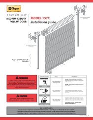
INSTALLATION INSTRUCTIONSES 10-337 / 6.1Barrel and BracketsECO# 0000 REVISION# 0000 BY: TOMB DATE: 04/07/11• Preparation of the Barrel and BracketsNote: Check to see if a hood support will be required. If so, refer to the “Hood Support <strong>Installation</strong>” sectionbefore proceeding to the barrel and brackets.1. Refer to the job construction drawings to determine the “coil side” of the opening, or the side of theopening on which the coil is to be installed. Then determine which jamb wall is your “operator side”, orside on which the operator is to be installed. The following instructions refer to these directional cues.Note: Units without operators (such as push-up units) are still considered to have an “operator” side.The shaft and job drawings will be marked with “operator” side regardless of the operation of the door sothat it can be used as a directional cue.2. Unpack the barrel assembly. Note the markings on the barrel, see Figure 6.1 below.L.H. ADJUST# OF TURNS OPENED / CLOSEDJOB NUMBEROPERATORLIFT POINTFigure 6.1 – Barrel Markings (Left Hand Adjust Shown3. Position the barrel assembly on the coil side of the opening, with the end marked “operator” towards the“operator side” of the opening. In order to alleviate the ring and bracket installation, place the barrelassembly on blocks or spacers such that it is elevated off the ground.Note: Choose sufficiently sized blocks. The barrel assembly should be elevated off the ground enoughthat the brackets can be installed without contacting the floor.4. Check to make sure the required number of turns is noted on the barrel, as shown in Figure 6.1. Consultthe distributor or the manufacturer if you cannot locate this information. Check that these numbers matchthe information provided on the job information. Take note of these numbers, as access to thisinformation may be obstructed once the curtain is installed.5. Typically the adjusting wheel is not shipped attached to the barrel. However, if the adjusting wheel isattached to the barrel, remove by loosening the bolt or set screws that secure the adjusting wheel to thebarrel and sliding the wheel off the inner shaft. See Figure 6.2.Figure 6.2 – Removal of Adjustor From Barrel Assembly6. Refer to the job information provided with the door to determine the correct ring type and quantity.7. Locate the rings in the hardware bag/box provided. Check that you were supplied the correct type andquantity. (Use Figure 6.3 as a visual aid.)
INSTALLATION INSTRUCTIONSES 10-337 / 6.2Barrel and BracketsECO# 0000 REVISION# 0000 BY: TOMB DATE: 04/07/118. Use the information in Figure 6.3 to install the rings.Note: It is critical that the rings are installed correctly in relation to the coiling direction, or the direction ofwrap as the door travels upward. The rings act as graduated spacers, meaning they increase in diametersuch that the curtain wraps in a consistent and smooth manner. Use the arrows on the figures below todetermine the correct orientation of the rings in relation to the coiling direction.SA0114 Extruded Rings:UPWARD WRAPDIRECTIONSA0114 OR SP020810-24 X 5/8 TRUSS HEAD TAPPED INTO5/16 DIAMETER X 7/8" LONG STUD<strong>Installation</strong>: Slide the ring over the barrel, noting direction of wrap, and rotate the ring fits over the 5/16” diameter x 7/8” longstud that is welded to the barrel. At this time there is no additional assembly required until the curtain is to be fastened to the barrel. In whichcase, the fastening section slat is fastened to the barrel using the #10-24 screws provided.SP0251 Cast Rings:UPWARD WRAPDIRECTIONLOCATE THE NUB, ON THEINNER PART OF THE RING, INTHE 7/16" DIAMETER HOLEPROVIDED IN THE BARREL3/8 SQNUTNUB3/8 X 1 1/4HEX HEADSP0251<strong>Installation</strong>: Use a small pry bar or large standard screwdriver to spread the gap in the ring by prying between bolt flangeand the nut cradle of the casting (see above). Slide the ring over the barrel, noting direction of wrap, and rotate the ring so the locating nub in the castingaligns with the locating hole in the barrel. Insert the 3/8 square nut into the nut cradle of the casting and the 3/8” x 1-1/4” hex bolt through the bolt flangein the casting and tighten to minimum 20 ft-lbs of torque. Be sure ring sits straight on barrel.Figure 6.3 – Ring <strong>Installation</strong>9. Locate the brackets. Determine the “operator” and “adjustor” brackets by referring to Figure 6.4. The“operator” bracket may vary significantly based on the operation of the door. The “adjustor” bracket willcontain a label with spring adjustment instructions.10. Remove the adjusting wheel if you haven’t previously done so, and slide the adjustor bracket over theinner shaft of the barrel assembly. The hood clip angles should be facing inwards. Install the adjustingwheel (see Figure 6.2).
INSTALLATION INSTRUCTIONSES 10-337 / 6.3Barrel and BracketsECO# 0000 REVISION# 0000 BY: TOMB DATE: 04/07/1111. If you have a conventional operator (with dropout pawl and fuselink), the operator bracket is shipped witha temporary plug holding the sprocket(s) and spacer washers in place on the bracket. Remove the plugand the bag of hardware attached to it, taking care not to lose the spacer washers positioned between thesprockets. Do not tighten the set screws in the bearing at this point. You may need to adjust the positionwhen attaching to the guides.Note: M100 and Push-up units will not have spacer washers, and will utilize only (1) sprocket on the“operator” bracket.12. Align the bearing, sprocket(s) and spacer washers and slide the assembly over the gear end until theinside face of the bracket is approximately 3 inches from the edge of the outer shaft. It is recommendedthat you install the keys, located in the bag of hardware you removed with the temporary plug, into eachsprocket at this stage. Do not tighten the set screws at this point.Note: Do not install the operator until the barrel and bracket assembly is hoisted into position andsecurely fastened to the guides. Installing the operator prior to this stage will cause the assembly to belopsided and cumbersome, making it difficult and potentially dangerous to hoist into position.COTTER PINADJUSTOR PINADJUSTORBRACKET BEARINGGEAR ENDRINGOPERATOR BRACKETADJUSTOR BRACKETHOOD CLIP ANGLEFigure 6.4– Brackets and Barrel Prior to <strong>Installation</strong> (M100 fire shutter brackets shown)
INSTALLATION INSTRUCTIONSES 10-337 / 6.4Barrel and BracketsECO# 0000 REVISION# 0000 BY: TOMB DATE: 04/07/11• Hoisting and Installing Barrel Assembly1. The following methods can be used for hoisting them into place: Crane Hoisting: Place a sling or lifting agent under the barrel assembly at the “lift point” provided onthe barrel, see Figure 6.1. Forklift Hoisting: Space the forks evenly under the “lift point” provided on the barrel, see Figure 6.1.Ensure that the barrel assembly is positioned close enough to the tips of the forks that the fasteningholes in the bracket can be aligned with those of the guides without the forks contacting the wall.Secure the barrel assembly to avoid the slipping off the tip of the forks.The addition of brackets may offset the balance slightly from when the “lift point” was marked. Check tomake sure the assembly is properly balanced before hoisting.2. Before hoisting, refer to the hardware sheet and ensure that the proper type and quantity of fastenerswere provided for the bracket installation.3. Check the job construction drawing for the type of unit (UL-9 or UL-10).a. If you have a UL-9 unit, measure the distance between the inside of the inner guide shapes.b. If you have a UL-10 unit, measure the distance between the outside of the inner guide shapes.c. Measure the distance between the brackets and compare that to the distance measured to the innerguide shapes. See Figures 6.5 and 6.6 below for bracket locations in relation to the guide shape.4. Center the barrel assembly between the guides, keeping approximately 2 feet of clearance between thebarrel assembly and wall/guides.5. Raise the barrel assembly up to the approximate bracket mounting level. The brackets should be clear ofthe outer and inner guide angles.Note: Position the brackets in the upright position, with the mounting holes facing the wall, before movingthe assembly towards the wall. It may be difficult to rotate the bracket when in close to the wall.6. Slowly maneuver the barrel assembly towards the guide, and align the mounting holes of the bracketswith those of the inner guide shapes.7. Insert the specified bolts and snug tighten, see Figures 6.5 and 6.6.UL-9 FACE OFWALL GUIDE5/16 NUT5/16 WASHERUL-9 BETWEENJAMBS GUIDE5/16 NUT5/16 WASHER5/16 SOCKETHEAD CAPSCREW5/16 SOCKETHEAD CAPSCREWFigure 6.5– UL-9 Bracket Mounting and Hardware
INSTALLATION INSTRUCTIONSES 10-337 / 6.5Barrel and BracketsECO# 0000 REVISION# 0000 BY: TOMB DATE: 04/07/11UL-10 FACEOF WALLGUIDEUL-10BETWEENJAMBS GUIDE1/2" NUT ANDWASHER1/2-13 ROUND HEADSQUARE NECK BOLT1/2" NUT ANDWASHER1/2-13 ROUND HEADSQUARE NECK BOLTFigure 6.6– UL-10 Bracket Mounting and Hardware8. Check to see that the barrel is positioned properly between the brackets. That is, so that the properamount of space is allowed between the barrel and the brackets. Typically the space is equal at both theoperator and adjustor side. Adjust as necessary.9. Place a level in the center of the barrel. If the shaft is not level: Check the dimensions of the brackets from the top of the bracket to the center of the barrel. Verify that the bracket mounting fasteners are the same distance from the top of the bracket.a. If the dimensions are not correct, contact the Service Department.b. If the dimensions are correct, the floor may be out of level, causing the bracket mounting holes inthe guides to be out of alignment.10. Fully tighten mounting bolts to the torque specifications in this manual. See Table 12.1.Proper pretension of the bracket mounting bolts will benefit the life of the bolts and brackets.11. If the adjusting wheel was not previously installed, install it now. Do not install the adjustor pin yet.12. Ensure the sprockets on the operator bracket are aligned as shown in Figure 6.7. Tighten the set screwsin the sprockets and bearing.Note: M100 units do not have brackets with multiple sprockets or gear trains that require alignment.COMBINATIONSPROCKETCOMBINATIONSPROCKETALIGNALIGNSPROCKETSPROCKETALIGNSPROCKETGEAR / SPROCKETASSEMBLYFigure 6.7– Conventional <strong>Fire</strong> <strong>Shutter</strong> Sprocket Alignment for Push-up Units (shown on left) and MotorChain and Crank Units (shown on right)
INSTALLATION INSTRUCTIONSES 10-337 / 7.1Motor Operator <strong>Installation</strong>ECO# 0000 REVISION# 0000 BY: TOMB DATE: 04/07/11• Motor Operator <strong>Installation</strong> (if required):1. Unpack the motor operator from the shipping box and retrieve the Operator Mounting Bracket and boltsprovided in the kit.2. There are a few motor mounting configurations that can be formed with the supplied components. Referto the shop drawings and components supplied with the kit in order to identify the specific style ofmounting ordered for the unit. Some of the types of mounting are: Vertical Bracket Wall Mounting Horizontal Front of Coil3. Mount the operator mounting bracket to the operator using the supplied fasteners.4. Mount the operator-mounting bracket to the operator bracket according to the shop drawings using thesupplied fasteners.5. Install controls and wire the operator. Refer to the wiring diagram provided with the operator for properconnections and voltages. The controls should be installed in an area from which the door/opening isclearly visible. This will allow an individual operating the unit to make a visual inspection of the openingfor any obstacles or other potential hazards before setting the door into motion.Note: Do not attempt to set the upper and lower limits until the curtain is installed.• Attaching Additional Bracing (if required):1. Attach a clip angle to the operator mounting bracket and the bracing angle to the clip angle. Snug allbolts.2. Mount the other supplied clip angle to the bracing angle and swing the bracing angle to the wall orstructural support.3. Align the mounting face of the clip angle with the face of the wall, mark and drill a mounting hole for thesize of the supplied mounting fastener, and secure the clip angle to the wall with the fastener.4. Square the operator-mounting bracket,adjusting the bracing angle as necessary,and fully tighten all the mounting bolts.5. Lift the motor operator into position on themounting bracket and align it with theappropriate hole pattern. See Figure 7.1for operator mounting details.6. Insert the fasteners included in the kitfrom the bracket side first into themounting foot of the operator and tightenthe nuts with lock washers.Note: All mounting bolts are supplied withnuts and lock washers.CLIP ANGLEATTACHMENTTHESE HOLESTO BE USEDTHRU 2 H.P.OPERATORSOPERATOR MOUNTINGBRACKETTHESE HOLES TOBE USED WITH 3H.P. OPERATORSMOUNTING HOLESTO OPERATOR SIDEBRACKET (4)Figure 7.1 - Additional Operator Bracing
INSTALLATION INSTRUCTIONSES 10-337 / 8.1Curtain <strong>Installation</strong>ECO# 0000 REVISION# 0000 BY: TOMB DATE: 04/07/11• Curtain <strong>Installation</strong>1. Remove the stoppers from the guides, or position them so they do not protrude into the opening.2. Open the curtain packaging. Leave the plastic straps that keep the curtain from uncoiling in place. It mayalso be beneficial to leave some of the packaging under the curtain to protect the finish during installation.3. The coil will be provided with the top of the curtain on the outside, thus leaving the fastening sectionsexposed. Position the coil on the floor between the guides so that the open end of the fastening sectionsis facing up and nearer the wall.4. Remove the outer guides.5. Locate the curtain attachment hardware provided with the unit. Refer to the job information to ensure youhave the correct type and quantity.6. Lift the coil until it is just below the shaft. Using appropriately rated ropes or straps, sling the coil from theshaft as shown in Figure 8.3. Remove the plastic strapping securing the coil at this point.7. Uncoil the curtain enough for the fastening sections to reach the attachment points on the shaft. Fastenthem by aligning the fastening section with the hole in the ring or shaft respectively, and fasten using theprovided hardware (see Figures 8.1 and 8.2). If the curtain is too heavy to uncoil by hand, use themethod described in the following step to get the fastening sections in position.APPLY 20 FT-LBS OFTORQUE TO THE 3/8-16HEX HEAD BOLT.APPLY 20 IN-LBS OFTORQUE TO THE #10-24SCREWS, LOCTITE 242THREADLOCKER ISRECOMMENDED.Figure 8.1 - UL-10 Fastening Section AttachmentFigure 8.2 - UL-9 Fastening Section Attachment8. Uncoiling a slung curtain using the operator/adjusting wheel: For units with operators, use the hand chain, crank or override feature of the motor to rotate the shaftin the “open” direction. Be sure not to overrun the limits of the motor. The upper motor limit mayhave to be adjusted to reel the entire curtain onto the shaft. Make sure the adjusting wheel is notpinned in place for this operation. For push-up units, turns can be added to the adjusting wheel in order to assist in rotating the shaft.Keeping count of the turns added to the spring at this stage will save installation time later.9. Continue to rotate the shaft, reeling the curtain out of the sling and onto the shaft until the bottom barreaches the bottom of the bracket.10. Replace the outer guides.11. Feed the bottom bar into the guides and lower the curtain until the bottom bar is below the stopperlocation.12. Since there is no spring tension holding thecurtain open, the curtain may fall if released. Ifthe operator cannot be used to hold the curtainin the open position, place C-clamps or vicegrips on the guides just below the bottom bar -or- rest the bottom bar on the slings used tohang the shaft in the previous steps to hold thedoor open.13. Replace the stoppers.Figure 8.3 - Installing the Curtain
B610PINSTALLATION INSTRUCTIONSES 10-337 / 9.1Spring Release SetupECO# 0000 REVISION# 0000 BY: TOMB DATE: 04/07/11• Applying Spring Turns:1. Refer to the job information or markings on the shaft for the number of spring turns required on the unit.2. To apply spring charge, remove cotter and stop pin from adjusting wheel. Lower the Dropout Pawl forConventional units (non-M100).3. Using two ½” diameter steel rods, approximately 18” long, apply spring torque by inserting both rods intoadjustor wheel one above the other.4. Rotate wheel in a direction of raising the curtain. Maintain applied torque with upper rod, while removing lowerrod. RE-insert this rod above the other and continue applying torque one notch at a time using this hand overhand procedure until the specified number of spring turns has been applied.5. Replace stop pin into adjustor wheel as shown in Figure 9.1 and insert the cotter pin to hold it in place. If you have an M100 unit, move on to step 6. If you have a Conventional unit, raise dropout pawl to engage with stop pin. Temporarily secure dropoutassembly in position with C-clamp or vise grips until the final spring tension adjustment is completed andfusible link chain has been installed.CAUTIONADJUSTING WHEEL IS UNDER SPRING TENSION AT ALL TIMES. TO PREVENT INJURY,ADJUSTMENT OF SPRING TORQUE OR RE-SETTING OF RELEASE MECHANISMS SHOULD ONLY BEPERFORMED BY AN EXPERIENCED DOOR INSTALLER.RESETTING INSTRUCTIONS1. RAISE CURTAIN TO FULL OPEN POSITION AND PLACE A CLAMP IN EACH GUIDE TO HOLDIN PLACE.2. RE-ENGAGE GEARED DROPOUT MECHANISM AT OPPOSITE BRACKET AND SECURE WITH ACLAMP. NOTE PUSH-UP DOORS WILL NOT HAVE DROPOUT MECHANISM AT OPPOSITEBRACKET.3. RE-APPLY SPRING TENSION ON ADJUSTING WHEEL USING TWO 5/8" DIAMETER STEELRODS IN HOLES IN WHEEL. ROTATE WHEEL IN DIRECTION OF RAISING THE CURTAINUNTIL STOP PIN IN WHEEL REACHES THE BOTTOM CENTER POSITION.4. WHILE MAINTAINING TENSION WITH ROD, SWING DROPOUT ARM UP TO ENGAGE STOP PINON ADJUSTING WHEEL. SECURE ARM IN POSITION WITH A CLAMP TO RETAIN SPRINGTENSION.5. RE-CONNECT FUSIBLE LINK CHAIN TO MAINTAIN MECHANISMS IN THE ENGAGEDPOSITION.6. REMOVE CLAMPS FROM BRACKETS AND GUIDES AND TEST OPERATION OF DOOR.COTTER PINSTOP PINDROPOUT PAWLFigure 9.1 - Spring Release Assembly for a Conventional <strong>Fire</strong> <strong>Shutter</strong>6. The spring should now hold the door in the open position. Remove any devices applied to hold the door in theopen position (clamps, slings, etc.)7. Check curtain for ease of operation. If the door operates correctly, skip to the fusible link setup, if not,continue to the next step.8. Final spring tension adjustment, if necessary, should be increased or decreased with the curtain in thefully open position. Insert one [two if necessary] ½” diameter steel rods into adjustor wheel.9. Holding the rod(s) firmly, disconnect the dropout assembly and lower until it clears stop pin on theadjustor wheel.Note: M100 units do not require a dropout assembly.10. Remove cotter pin and stop pin from adjustor wheel and begin to increase or decrease tension. To increase tension, rotate the wheel in the direction of raising the curtain. To decrease tension, carefully rotate the wheel in the direction of lowering the curtain.11. Recheck the balance in 1/8 rotation increments (one notch at a time). Re-insert stop pin, cotter pin andengage dropout assembly into operating position immediately after each turn.Note: If you have difficulty balancing the door, or the number of turns required to balance the door variessignificantly from the quantity provided, contact the Service Department.
81SIDE WALLTO DROPOUTMECHANISM(1) RELEASEDEVICE, SEE NOTE 712" MIN.12" MIN.97FLAME BAFFLEASSEMBLYCOIL SIDE OF OPENING12" MAX.SEENOTE 112" MIN.6 34HOOD10(4) 'S' HOOK5(2) #8 SASH CHAIN(3) FUSIBLE LINK,FM APPROVED(3) FUSIBLE LINK,UL APPROVED(5) SPLIT KEY RINGDROPPED CEILINGSEE NOTE 7.(6) DRAW BAR SPRING12" MIN.2TO DROPOUTMECHANISM4" SEENOTE 1SIDEWALL12" MIN.(8) EYE BOLT(9) LOUVER12"MIN.(7) TURNBUCKLE(10) CONDUIT4"NOTES:CEILINGFASCIA SIDE OF OPENING1. A fusible link or smoke / heat detector cannot be located within 4" x 4" of the corner of the ceilingand side wall. Also, the fusible link or smoke / heat detector cannot be located more than 12" fromthe ceiling, unless the ceiling is dropped, in which case louvers are supplied and the links are placedabove the ceiling.2. All doors must be drop tested twice after installation to ensure proper automatic closing operation.3. The flame baffle assembly is not part of the fusible link arrangement.4. A dropped ceiling with hood concealed is shown as well as the ceiling overhead with hoodexposed. Hardware is shown for both cases, but is not provided for both. If there is a droppedceiling, be sure there is sufficient clearance so that the dropout mechanism(s) can function properly.5. A 12" minimum of chain is required between chain connections / splices and anywhere the chainmust travel through (eye bolt, split key ring, conduit, etc.) in order to allow the dropout mechanism tofunction correctly.6. The detail above is for reference only. Ultimately, the fusible link arrangement must be inaccordance with the local authority having jurisdiction per NFPA 80.7. If there is no release device, the section of sash chain shown to the release device is not needed.If there is no dropped ceiling, this section of sash chain shown above the ceiling is not needed.10HOOD REF.INSTALLATION INSTRUCTIONSES 10-337 / 9.2Spring Release SetupECO# 0000 REVISION# 0000 BY: TOMB DATE: 04/07/11• Installing the Fusible Link Assembly (if required):1. Refer to Figure 9.2 and the job construction drawings for fusible link installation for conventional fire doors.Note: Push-up units only require a fusible link assembly on (1) side.12" MIN.12" MIN.Figure 9.2. Fusible Link <strong>Installation</strong> for Conventional <strong>Fire</strong> Doors
SIDE WALL8FLAME BAFFLEASSEMBLY9(1) #8 SASH CHAIN(2) FUSIBLE LINK,FM APPROVED(2) FUSIBLE LINK,UL APPROVED(3) 'S' HOOK(4) SPLIT KEY RING12" MAX.SEEHOOD105DROPPED CEILINGSEE NOTE 7.TO M100OPERATORRELEASEMECHANISM(5) TURNBUCKLE(6) EYE BOLT(7) LOUVER(8) CONDUITSIDEWALLNOTES:CEILING1. A fusible link or smoke / heat detector cannot be located within 4" x 4" of the corner of the ceilingand side wall. Also, the fusible link or smoke / heat detector cannot be located more than 12" from theceiling, unless the ceiling is dropped, in which case louvers are supplied and the links are placed abovethe ceiling.2. All doors must be drop tested twice after installation to ensure proper automatic closing operation.3. The flame baffle assembly is not part of the fusible link arrangement.4. A dropped ceiling with hood concealed is shown as well as the ceiling overhead with hood exposed.Hardware is shown for both cases, but is not provided for both. If there is a dropped ceiling, be surethere is sufficient clearance so that the dropout mechanism(s) can function properly.5. A 12" minimum of chain is required between chain connections / splices and anywhere the chainmust travel through (eye bolt, split key ring, conduit, etc.) in order to allow the dropout mechanism tofunction correctly.6. The detail above is for reference only. Ultimately, the fusible link arrangement must be inaccordance with the local authority having jurisdiction per NFPA 80.7. If there is no dropped ceiling, the section of sash chain shown above the ceiling is not needed.INSTALLATION INSTRUCTIONSES 10-337 / 9.3Spring Release SetupECO# 0000 REVISION# 0000 BY: TOMB DATE: 04/07/112. Refer to Figure 9.3 and the job construction drawings for fusible link installation for M100 fire doors.3 4NOTE 1 43EYE BOLT ONBRACKET BYOTHERS2COIL SIDE OF OPENING4" SEENOTE 14"FASCIA SIDE OF OPENING12"MIN.10HOOD REF.12" MAX.SEENOTE 1Figure 9.3. Fusible Link <strong>Installation</strong> for M100 <strong>Fire</strong> Doors
INSTALLATION INSTRUCTIONSES 10-337 / 9.4Spring Release SetupECO# 0000 REVISION# 0000 BY: TOMB DATE: 04/07/11• Installing through wall conduit for fusible links:Note: Read these instructions carefully before installing through wall conduit.1. When a through wall fusible link is specified the hardware package will be supplied with a length of 1/2”EMT conduit and two 3/4” diameter set screw collars to secure the sleeve in the wall.2. Determine the location where the conduit is to be installed and mark the wall. For information on locationof conduit and fusible links refer to NFPA 80 Standard for <strong>Fire</strong> Doors and Other Opening Protective’s.3. Drill a 3/4” diameter hole straight through the wall at the location required for the through wall conduitinstallation.4. Install one of the set screw collars on the end of the 1/2” diameter EMT conduit supplied with thehardware so the end of the conduit is back slightly from the face of the collar and tighten set screw.5. Insert the conduit into the hole drilled in the wall and install the other collar on the conduit on the oppositeside of the wall so the collars on both sides are against the face of the wall and hold the conduit securelyin place.6. Mark the conduit at the second collar so it can be cut to the proper length so both ends are back slightlyfrom the faces of the collars.7. Remove the conduit assembly from the hole through the wall and trim off the excess length at the locationmarked.8. With a circular file or de-burring tool clean up both ends of the conduit so there are no sharp edges thatcan obstruct the proper operation of the fusible link setup.9. Reinstall the conduit assembly in the wall as described in steps 4 and 5 and tighten the set screws tosecure the conduit in the wall.10. Install the through wall fusible link setup once the door installation is complete.Once the fusible link setup is installed the conduit must not be plugged with fire-stopping products orother sealants that may obstruct proper operation of the fusible link system.SET SCREWCOLLAR BOTHSIDES OF WALL1/2" EMTCONDUIT
INSTALLATION INSTRUCTIONSES 10-337 / 10.1Hood, Fascia, and CoversECO# 0000 REVISION# 0000 BY: TOMB DATE: 04/07/11• Hood Support <strong>Installation</strong>:1. Determine what type of hood support is required and how many there will be. See below for different types.a. Hood supports will be noted on the elevation view of the job construction drawings.SUPPORTMOUNTINGANGLESQUARE HOODFigure 10.1 - Hood SupportsSQUARE HOODWITH FASCIASQUARE HOOD WITHFASCIA AND LINTELBRUSH MOUNTING2. If a lintel brush is required, installit at this time. Figure 10.2 belowshows a lintel brush mountingwith a hood support with thebrush mounting modification.3. See Figure 11.3 for mounting thelintel brush channel to the guide.HOOD/FASCIASUPPORT WITHBRUSH MOUNTINGSLATNote: Be sure the lintel brush doesnot interfere with the bottom bar.4. Determine where the support(s)will be located between theguides.a. If multiple supports arerequired, see the jobconstruction drawings todetermine the centerline ofeach.b. If a single support isrequired, it will be located atthe center of the unit.5. Mark a line on the lintel or ceiling(for units without a lintel) at thecenterline of each support.6. Check the construction at thesupport locations to be sure it isstrong enough to handle theweight of the hood.Note: If the construction is not strongenough, do not proceed untilrectified.FASCIALINTEL BRUSHASSEMBLYAPPLY SEALINGCOMPOUND HEREFigure 10.2 – Lintel Brush Channel Mounting to Hood SupportLINTEL BRUSHCHANNELFIRE SHUTTERGUIDELINTEL BRUSHMOUNTING HOLEAPPLY SEALINGCOMPOUND BETWEENCHANNEL AND WALLFOR FACE OF WALL UNITSLINTEL BRUSHCHANNELFIRE SHUTTER GUIDEFigure 10.3 – Lintel Brush Channel Mounting to GuideBRACKETLINTEL SEALCHANNEL FASTENER
INSTALLATION INSTRUCTIONSES 10-337 / 10.2Hood, Fascia, and CoversECO# 0000 REVISION# 0000 BY: TOMB DATE: 04/07/117. Determine where the top of the coil will be.a. This is typically at the top of the wall angle or intermediate angle.b. If there is no wall or intermediate angle, see the job construction drawings for the distance from thebottom of the unit to the top of the coil.c. If there is a ceiling at the top of the coil, skip the next step.8. Mark a line at the top of the coil at both guides of the unit. Project the lines together to make a continuous line.This will help locate the top of the hood support which will keep the hood level.9. If there is no lintel/header, the hood support will be located based on the fascia side of the guide.a. If the unit is between jambs with 4 angle guides, a fascia mounting channel is typically provided.b. If the unit is between jambs with 2 angle guides mounted to a tube, a fascia mounting channel is notprovided, and the fascia is mounted to the fascia side of the tube.10. Project a line from the fascia mounting location (fascia mounting channel or fascia side of the tube) from oneguide to the other.11. Mark a line at the support centerline along the fascia line.12. Prepare the location of the attachment point of the support(s) prior to installing the barrel. This will makeinstalling the support much easier when the time comes to attach it to the lintel/header or ceiling.a. Hold the support in place at the determined location and mark the mounting hole locations.b. Drill holes in the construction.13. Attach the hood support to the lintel/header or ceiling to be sure the mounting holes were located properly.14. Remove the hood support and proceed to the “Barrel and Brackets” section.15. Once the barrel, brackets, curtain are installed, and necessary testing was done on the unit, re-install the hoodsupport.• Hood and Fascia <strong>Installation</strong>:1. Check the job construction drawings to see if the hood has multiple parts (such as a two sided hood with afascia, two sided hood without a top piece, three sided hood with a flared top bead, etc). See Figure 10.4 forpossible hood configurations.2. Fasten the hood and fascia accordingly using the fasteners provided. Ensure hoods with multiple sectionsoverlap correctly. Square hoods should end flush with the outer edge of the brackets.3. If there is a hood support provided, the hood sections do not overlap at the hood support. They should buttagainst each other and a hood splice cover is provided to cover the joint.Note: If there is a hood support, pre-drill holes in it to ease hood attachment. A #21 drill size is recommended.3-SIDEDHOOD2-SIDEDHOOD3-SIDEDHOOD WITHFLAREDBEAD2-SIDEDFASCIA1-SIDEDFASCIA1-SIDED FASCIAFOR LINTELBRUSH MOUNTINGFigure 10.4 - Hood Configurations
INSTALLATION INSTRUCTIONSES 10-337 / 10.3Hood, Fascia, and CoversECO# 0000 REVISION# 0000 BY: TOMB DATE: 04/07/11• Cover installation:1. Once the unit is installed and operating correctly, the covers can be installed.2. Hood screws may have to be removed and reinstalled to install covers properly.Note: Mechanism covers are required on all conventional fire doors to prevent dropout mechanisms frombeing obstructed. These covers are optional on M100 fire doors.SLOT FORFUSELINK CHAINSLOT FORFUSELINK CHAINHOODHOODHOODHORIZONTAL FRONTOF COIL MOTORM100 VERTICALBRACKET MOTORVERTICAL BRACKETMOTOR OR CRANKOPERATEDSLOT FORFUSELINK CHAINHOODHOODADJUSTORFigure 10.5 – Mechanism CoversPUSH-UP OPERATEDNote: Mechanism covers differ from operator and adjustor covers in that operator and adjustor covers providea complete enclosure.3. If an operator or adjustor cover is provided, individual installation instructions are provided with each coveralong with the necessary hardware to attach the cover.4. Once the cover is installed, operate the door a few more times to be sure there is no interference between themoving components inside the cover and the cover itself.5. If the door is mounted on the exterior of the building, a bead of silicone sealant should be applied around theentire perimeter of the cover, as it will provide additional protection to the door components.Figure 10.6 – Hood and Cover Screw (#10-16 x 1/2”)
INSTALLATION INSTRUCTIONSES 10-337 / 11.1Drop TestECO# 0000 REVISION# 0000 BY: TOMB DATE: 04/07/11• Drop Testing:Note: Perform door and electrical operator maintenance. It is important to make sure that the dooroperates properly in the normal mode of operation before testing the automatic closing mechanisms.1. Inspect the fusible links and chain arrangements. Links and chain should be clean and unpainted.Links and “S” hooks should be at least 12” away from any eyebolts or thru wall fixtures to insureenough chain travel for mechanisms to drop out. Check for any other points where the chain mayhang up.2. Check release arms on brackets. Make sure that they are NOT tied up in place and that nothing willblock proper drop out of arms.3. The door should be drop tested twice. The first test should ensure the proper operation of the closingmechanism and full closure of the opening. The second test should verify that the automatic-closingdevice has been reset correctly (reference NFPA 80).4. Drop test door to check automatic closing mechanism. Make sure that the door is in full openposition. Initiate automatic closing by separating the chain at the “S” hook. Door closing speed shallnot be less than 6” per second nor more than 2’ per second. The door must close completely with thebottom bar resting on the sill.5. If problems occur during the drop test, consult installation instructions or door manufacturer.6. Reset door mechanisms following manufacturer’s instructions.7. A second drop test should be performed. This one should be witnessed by a representative of theowner.8. Reset door.9. Door releasing devises, smoke detectors and other special control equipment may be tested if ownerrequests. Follow manufacturer’s instructions for testing. If smoke detectors are connected to acentral fire alarm system, they should not be tested.10. When repair parts are required, they must be purchased from the original door manufacturer.The following documents should have been provided with the <strong>Fire</strong> Door: Rolling Steel <strong>Fire</strong> Doors Drop Testing and Annual Follow-Up Owners Guidelines Rolling Steel <strong>Fire</strong> Door Initial & Annual Drop Test FormIf you cannot locate these documents, or need replacements documents, contact the Service Department.
INSTALLATION INSTRUCTIONSES 10-337 / 12.1Torque SpecificationsECO# 0000 REVISION# 0000 BY: TOMB DATE: 04/07/11Table 12.1 – Torque Recommendations for Guide Assembly and Wall FastenersBolt size/typeTorque (ft lbs) a1/4-20 Grade 2 steel bolt 65/16-18 Black Oxide Socket Cap 253/8-16 18-8 stainless steel bolt 203/8-16 Grade 2 steel bolt 203/8-16 Grade 5 steel bolt 311/2-13 Grade 5 steel bolt 751/2-13 Grade 8 steel bolt 1075/8-11 Grade 8 steel bolt 2123/4-10 Grade 8 steel bolt 376a The recommended torque for steel bolts is based on aplated bolt that has not been lubricated.Table 12.2 – Torque Recommendations for Solid Masonry Wall AnchorsManufacturer / Torque (ft lbs) aAnchor Size (nominal) Simpson Wedge-All Hilti-Kwik Bolt 33/8 30 201/2 60 405/8 90 853/4 150 150a Torque values for grout filled block are different, reference bolt manufacturer for these values.
INSTALLATION INSTRUCTIONSES 10-337 / 13.1Maintenance ScheduleECO# 0000 REVISION# 0000 BY: TOMB DATE: 04/07/11• Maintenance Schedule:Note: If any of the following problems exist, do not operate the door until repaired.ComponentWhat to look for and how often thecomponents must be inspected:Are any curtain components damaged (slats,endlocks, etc.)?Is bottom bar damaged?Are bottom bar fasteners in place and properlytightened?Weekly Monthly Quarterly What to do if problem exists:XXXContact Service about replacing damagedparts.Contact Service about replacing damagedparts.Fasteners must be inspected/replaced andproperly tightened.Curtain &Bottom BarBracketsAre fasteners attaching curtain to the barrel inplace and properly tightened?Do you notice any hang-ups, jamming or otherproblems preventing the door from movingsmoothly throughout the opening?Do you notice any odd or excessive noisewhen the door is operated?If there is a bottom seal, is it damaged?If there is locking, does it function properly?Are brackets plumb and perpendicular withwall?Are bracket fasteners in place and properlytightened?Do you notice signs of excessive wear on thebearings (i.e. binding, excessive noise, etc.)?XXXXXXXFasteners must be inspected/replaced andproperly tightened.Check for external issues, if none exist,contact Service.Check for external issues, if none exist,contact Service.Contact Service about replacing damagedparts.Check for external issues, if none exist,contact Service.Contact Service.Is adjusting wheel & pin secure? X Contact Service.XFasteners must be inspected/replaced andproperly tightened.If there is a grease fitting, apply grease, ifnot, contact Service.Is drive chain sufficiently lubricated? X Apply chain lube.Is drive chain in need of tightening?XContact Service for instructions on how totension the chain.Is drive or driven sprocket damaged?Are wall fasteners in place and properlytightened?Are guide assembly fasteners in place andproperly tightened?XXXContact Service about replacing damagedparts.Fasteners must be inspected/replaced andproperly tightened.Fasteners must be inspected/replaced andproperly tightened.GuidesHood andFasciaIs guide gap dimension correct?Are any of the guide parts bent or damaged? X Contact Service.Are stoppers loose, damaged, or missing?Is hood/fascia dented or damaged?Is curtain rubbing against the hood/fascia?Is hood/fascia level?Are guide assembly fasteners in place andproperly tightened?Is hood support level?XXXXXXXCheck job construction drawings and adjustgap as required. If job constructiondrawings are not available, contact Service.Stoppers must be inspected/replaced andproperly tightened.Remove hood/fascia. Repair if possible. Ifnot leave hood/fascia off and contactService.Hood/fascia may have been damaged.Contact Service.Check fasteners, they may be loose ormissing. Replace as soon as possible.Fasteners must be inspected/replaced andproperly tightened.Check fasteners, they may be loose ormissing. Replace as soon as possible.
INSTALLATION INSTRUCTIONSES 10-337 / 13.1Maintenance ScheduleECO# 0000 REVISION# 0000 BY: TOMB DATE: 04/07/11Door operationDoes the door require excessive force toopen?If the door contains locking, does the lockingmechanism function properly and securelyhold the door in the closed position?XXCheck for hang-ups or obstructions.Ensure spring tension is set correctly.Contact Service.Check for damage and other externalissues. Contact Service.If there is a sensing edge, does it functionproperly?XCut power and check for loose wires.Contact Service for further instruction.Are the fasteners attaching the motor-to-themounting bracket, and mounting bracket-tothedoor bracket secure?XFasteners must be inspected/replaced andproperly tightened. Contact Service forreplacement hardware.Are the sprockets properly aligned?XRealign the sprockets as secure using theset screws. Recheck chain tension.Motor OperatorAre the sprocket keys properly aligned withsprockets and securely fastened with the setscrews?XReposition the keys so they fully engagethe keyway in the sprocket. Tighten the setscrews.Is the door stopping correctly at the open(before bottom bar contacts the stoppers) andclosed (as soon as the bottom bar contactsthe floor) positions?XLimits may have to be adjusted in the motoroperator. Refer to the operator owner’smanual or contact Service.Is the operator functioning normally?XRefer to the Operator TroubleshootingTable on the following page to diagnose theproblem.
INSTALLATION INSTRUCTIONSES 10-337 / 13.1Maintenance ScheduleECO# 0000 REVISION# 0000 BY: TOMB DATE: 04/07/11• Operator Troubleshooting:Note: If you suspect you are having an issue with your operator, use the following table to determine the potential causes.If the provided solution does not eliminate the issue, or the table does not address your particular problem, contact theService Department.Component Problem Potential Cause SolutionMotor Operator does not runwhen OPEN or CLOSE buttonis pushedThe circuit breaker may be flipped orfuse blown.The thermal overload may be tripped.Manual interlock switch is open (onunits with emergency operator).External interlock may be opened.Reset breaker or replace fuse. ContactService if replacement fuse is needed.Reset thermal overload.Close manual interlocks.Close external interlock.Motor operator runs but thedoor does not moveSprocket key may be missing or drivechain may be broken.Clutch may be slipping.Door or drive chain may be jamming.Contact Service for repair parts. Installkey or replace chain.Adjust if possible. Contact Serviceotherwise.Check for hang-ups or obstructions. Tryto operate manually. If issue persists,contact Service.Motor OperatorMotor hums but does not runDead phase in 3 phase system.Brake does not release.Check power supply.Check power to brake solenoid.Open motor winding.Check that all connections are secure.Motor operator runs in wrongdirection and limits do notfunction3 phase operator power supply is out ofphase.Interchange any 2 power leads to unit.Door drifts when motor shutsoffBrake may be improperly adjusted orbroken.Check brake components. ContactService for replacement parts or adjustinstructions.Motor operator does not shutoff at full OPEN or at fullCLOSE positionLimits may need adjustment.Sprocket on limit shaft may be slippingor limit drive chain may be broken.Refer to the operator owner’s manual toreadjust limits.Ensure sprocket key is correctlyinstalled and set screws are tightened.Contact Service for replacement chain ifbroken.Limit switch may be defective.Contact Service.Drive chain may be too loose, allowingthe chain to jump sprocket teeth.Adjust chain to proper tension. ContactService for additional information.Limit SwitchesLimit switch does not holdsettingLimit nut retainer not engaging slots inlimit nuts.Be sure retainer is securely engaged inslots of both limit nuts.Limit nuts binding on screw threads,allowing them to jump position onretainer.Lube screw thread. Check that limitnuts turn freely.
INSTALLATION INSTRUCTIONSES 10-337 / 14.1Appendix AECO# 0000 REVISION# 0000 BY: TOMB DATE: 04/07/11• Sealant application for NFPA 105 / UL 1784 compliance:Note: Read this sheet before installing unit.Assembly must be properly sealed with caulking and brush gasketing must be installed for unit tofunction in accordance with the performance criteria of NFPA 105.A multi-purpose sealant such as Dow Corning RTV silicone sealant #732 or equal must be applied toall surfaces of the unit which come into contact with the door opening and to all mating surfaces of thedoor assembly where air leakage is a possibility. This is especially important between the matingpieces of the guide assembly and between the brush seals and the guide.This material must be field applied according to the manufacturer’s recommendations. It is best todrill or machine all parts and pre-fit them prior to applying the sealant material. This process willensure the neatest job possible and help to determine the amount of sealing compound which needsto be applied. Application of only a very small amount of material is required to seal closely matingsurfaces. The use of too much sealant will cause oozing when fasteners are tightened down makingit necessary to clean off excess after material has cured.Refer to the “Guides” and “Hood, Fascia, and Covers – Lintel Brush” sections in this manual forinstructions on installing brushes and applying the silicone sealing compound.