Calibration of a Terrestrial Laser Scanner - Institute of Geodesy and ...
Calibration of a Terrestrial Laser Scanner - Institute of Geodesy and ... Calibration of a Terrestrial Laser Scanner - Institute of Geodesy and ...
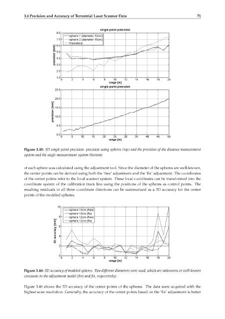
70 3. Calibration of Terrestrial Laser Scanner3.6.1 Single Point PrecisionThe precision of one single point is derived by two methods. The first one is based on the identified preci¬sion for the distance component (ss) and the encoder components for the horizontal direction (shz) and thevertical direction (sv). A theoretical error budget for one single point (sp) can be calculated by:sp = ^jsl+ s2y + s\ (3.15)withsxsyszO •ss= s tan{2> Shz) (3.16)= s tan{2> sv)For the precision of the x-component, the trifold precision,i.e. standard deviation, is used since it refersto 99.9% of measurements. For the y-component and the z-component,the distance s has to be takeninto account as well as the trifold precision of the angle measurement system.The second method usesthe acquired point cloud to derive a single point precision. Spheres were scanned and the center pointswere calculated by applying the adjustment algorithm, cf. Section 3.1.5. The resultingmean error of theunit weight (so) defines the precision of one single coordinate. Thus, the precision of one single pointcontaining three coordinates can be determined by:sp = a/3•s0. (3.17)The spheres were positioned along the calibration track line in varying ranges so that the development ofthe precision of one single point can be derived. Figure 3.45 shows the results obtained by the two differentmethods.Since the second method can only be applied up to ranges of approximately 20 m, the upperfigure is also limited up to this range. Reasons for the limited range are the quality and the quantity of theacquired point cloud decrease rapidly with the range, cf. Section 3.2.2. The precision obtained by the secondmethod is verified using two spheres with different diameters, i.e.12 cm and 15 cm. The values lie about5 mm and fit with each other. In addition, the theoretical precision based on the first method increases withthe range. The lower figure shows the development of the precision. The noise of one single point reachesvalues in the order of some centimeters in ranges of more than 30 m.In summary, it can be concluded that the two methods fit each other and show a precision for one singlepoint of less than 1 cm up to a range of 20 m. The development of the theoretical precision gives an impres¬sion of the resulting precision in ranges of more than 30 m, which increases up to 2 cm. The difference in thetwo methods is that the derived theoretical precision is based on an angle of incidence of 90 °, which meansthe laser beam hits the object normal. A variation of the angle of incidence leads to lower distance precisionand also results in lower single point precision, cf. Section 3.5.2. On the contrary, the method using thespheres takes the varying angle of incidence into account. Furthermore, the investigationcan be continuedfor different reflectivity values. The spheres used are white in colour, approximating a reflectivityAlso, the distance accuracy required for the first method refers to a reflectivityof 90 %.of 90 %.3.6.2 Accuracy of Modeled Objects (Spheres)The accuracy of modeled objects is shown exemplarily by considering the calculated center point of spheres.The spheres with two different diameters, i.e. 12 cm and 15 cm, were positioned along the calibration trackline and were scanned with three different scan resolutions.Based on the acquired data, the center point
.3.6 Precision and Accuracy of Terrestrial Laser Scanner Data 71usingle point precision0sphere 1 (diamete 12cm),E600.
- Page 30 and 31: 20 2. Components of Terrestrial Las
- Page 32 and 33: 22 2. Components of Terrestrial Las
- Page 34 and 35: 24 3. Calibration of Terrestrial La
- Page 36 and 37: 26 3. Calibration of Terrestrial La
- Page 38 and 39: '28 3. Calibration of Terrestrial L
- Page 40 and 41: 30 3. Calibration of Terrestrial La
- Page 42 and 43: 32 3. Calibration of Terrestrial La
- Page 44 and 45: "[m] of system 90%) 3540 distance b
- Page 46 and 47: !36 3. Calibration of Terrestrial L
- Page 48 and 49: 138 3. Calibration of Terrestrial L
- Page 50 and 51: 40 3. Calibration of Terrestrial La
- Page 52 and 53: 42 3. Calibration of Terrestrial La
- Page 54 and 55: 44 3. Calibration of Terrestrial La
- Page 56 and 57: 46 3. Calibration of Terrestrial La
- Page 58 and 59: 48 3. Calibration of Terrestrial La
- Page 60 and 61: 50 3. Calibration of Terrestrial La
- Page 62 and 63: 52 3. Calibration of Terrestrial La
- Page 64 and 65: 54 3. Calibration of Terrestrial La
- Page 66 and 67: 56 3. Calibration of Terrestrial La
- Page 68 and 69: Inormal axis,intersectionpoint axis
- Page 70 and 71: 60 3. Calibration of Terrestrial La
- Page 72 and 73: 62 3. Calibration of Terrestrial La
- Page 74 and 75: 64 3. Calibration of Terrestrial La
- Page 76 and 77: j/-*'.-,•66 3. Calibration of Ter
- Page 78 and 79: 68 3. Calibration of Terrestrial La
- Page 82 and 83: 72 3. Calibration of Terrestrial La
- Page 84 and 85: 74 4. Static Laser Scanning4.1.2 Mi
- Page 86 and 87: 76 4. Static Laser ScanningOptical
- Page 88 and 89: 78 4. Static Laser Scanningmaximum
- Page 90 and 91: 80 4. Static Laser Scanningand gene
- Page 92 and 93: 82 4. Static Laser Scanning• Ther
- Page 94 and 95: 84 4. Static Laser Scanning4.3.3 NU
- Page 96 and 97: 86 4. Static Laser Scanning
- Page 98 and 99: 88 5. Kinematic Laser Scanningmirro
- Page 100 and 101: 90 5. Kinematic Laser ScanningThe a
- Page 102 and 103: 92 5. Kinematic Laser Scanninghas a
- Page 104 and 105: '94 5. Kinematic Laser Scanningbeam
- Page 106 and 107: —96 5. Kinematic Laser ScanningTa
- Page 108 and 109: ''iI98 5. Kinematic Laser ScanningA
- Page 110 and 111: 40323 o.o; 50545 aT [jjs] 1.0().2 S
- Page 112 and 113: 102 5. Kinematic Laser Scanning5.3
- Page 114 and 115: —1.104 5. Kinematic Laser Scannin
- Page 116 and 117: propagationresults series Taylorter
- Page 118 and 119: 108 5. Kinematic Laser Scanningonly
- Page 120 and 121: cf.aroundframe regardingsetupusinga
- Page 122 and 123: 112 6. Applications of Terrestrial
- Page 124 and 125: 114 6. Applications of Terrestrial
- Page 126 and 127: 116 6. Applications of Terrestrial
- Page 128 and 129: 118 6. Applications of Terrestrial
.3.6 Precision <strong>and</strong> Accuracy <strong>of</strong> <strong>Terrestrial</strong> <strong>Laser</strong> <strong>Scanner</strong> Data 71usingle point precision0sphere 1 (diamete 12cm),E600.


