

Calibration of a Terrestrial Laser Scanner - Institute of Geodesy and ...
Calibration of a Terrestrial Laser Scanner - Institute of Geodesy and ...
Calibration of a Terrestrial Laser Scanner - Institute of Geodesy and ...

Create successful ePaper yourself
Turn your PDF publications into a flip-book with our unique Google optimized e-Paper software.
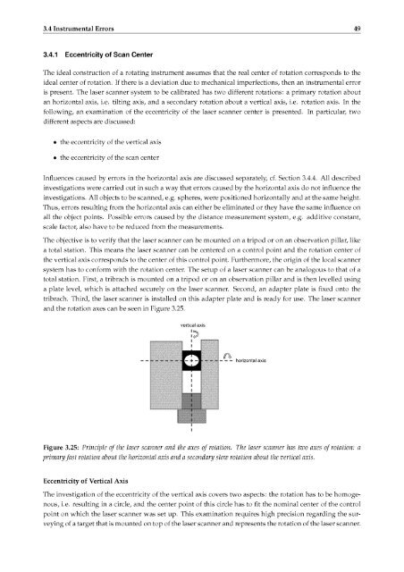
3.4 Instrumental Errors 493.4.1 Eccentricity <strong>of</strong> Scan CenterThe ideal construction <strong>of</strong> a rotating instrument assumes that the real center <strong>of</strong> rotation correspondsideal center <strong>of</strong> rotation. If there is a deviation due to mechanical imperfections,is present. The laser scanner system to be calibrated has two different rotations: a primaryto thethen an instrumental errorrotation aboutan horizontal axis, i.e. tilting axis, <strong>and</strong> a secondary rotation about a vertical axis, i.e. rotation axis. In thefollowing, an examination <strong>of</strong> the eccentricity <strong>of</strong> the laser scanner center is presented. In particular, twodifferent aspectsare discussed:• the eccentricity <strong>of</strong> the vertical axis• the eccentricity <strong>of</strong> the scan centerInfluences caused by errors in the horizontal axis are discussed separately,investigations were carried out in such a way that errors caused bycf. Section 3.4.4.All describedthe horizontal axis do not influence theinvestigations. All objects to be scanned, e.g. spheres, were positioned horizontally <strong>and</strong> at the same height.Thus, errors resulting from the horizontal axis can either be eliminated or they have the same influence onall the object points. Possible errors caused by the distance measurement system, e.g. additive constant,scale factor, also have to be reduced from the measurements.The objective is to verify that the laser scanner can be mounted on a tripod or on an observation pillar, likea total station.This means the laser scanner can be centered on a control point <strong>and</strong> the rotation center <strong>of</strong>the vertical axis corresponds to the center <strong>of</strong> this control point. Furthermore, the origin <strong>of</strong> the local scannersystem has to conform with the rotation center. The setup <strong>of</strong> a laser scanner can be analogous to that <strong>of</strong> atotal station. First, a tribrach is mounted on a tripod or on an observation pillar <strong>and</strong> is then levelled usinga plate level, which is attached securely on the laser scanner. Second, an adapter platetribrach. Third, the laser scanner is installed on this adapter plate <strong>and</strong> is ready<strong>and</strong> the rotation axes can be seen in Figure 3.25.is fixed onto thefor use. The laser scannervertical axis— — —horizontal axisFigure 3.25: Principle <strong>of</strong> the laser scanner <strong>and</strong> the axes <strong>of</strong> rotation. The laser scanner has two axes <strong>of</strong> rotation: aprimary fast rotation about the horizontal axis <strong>and</strong> a secondaryslow rotation about the vertical axis.Eccentricity <strong>of</strong> Vertical AxisThe investigation <strong>of</strong> the eccentricity <strong>of</strong> the vertical axis covers two aspects: the rotation has to be homoge¬nous, i.e.resulting in a circle, <strong>and</strong> the center point<strong>of</strong> this circle has to fit the nominal center <strong>of</strong> the controlpoint on which the laser scanner was set up. This examination requires high precision regardingthe sur¬veying <strong>of</strong> a target that is mounted on top <strong>of</strong> the laser scanner <strong>and</strong> represents the rotation <strong>of</strong> the laser scanner.


