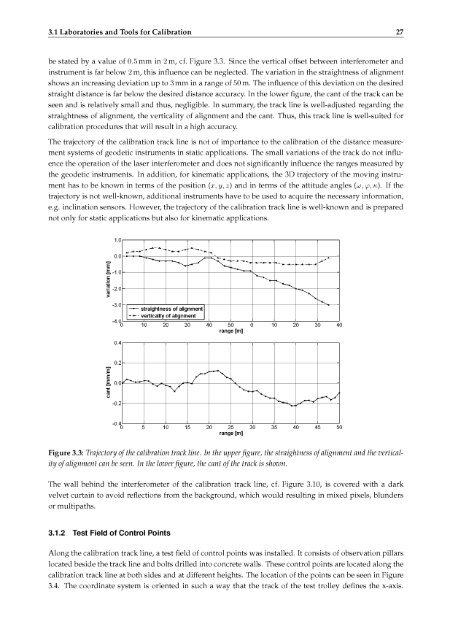
26 3. <strong>Calibration</strong> <strong>of</strong> <strong>Terrestrial</strong> <strong>Laser</strong> <strong>Scanner</strong>3.1 Laboratories <strong>and</strong> Tools for <strong>Calibration</strong>The IGP is equipped with various kinds <strong>of</strong> laboratory facilities, test fields, etc. Thus, geodetic instrumentscan be calibrated regarding different aspects.In the following, some laboratory facilities <strong>and</strong> test fields,which play an important role in the calibration <strong>of</strong> the terrestrial laser scanner, are introduced.3.1.1 <strong>Calibration</strong> Track LineThe calibration track line at the IGP has a length <strong>of</strong> roughly 52 m. A trolley moves on the track line, eitherautomatically or manually, cf. Figure 3.2. This trolley is tracked by a laser metric system (HP 5529A dy¬namic calibrator), which is based on interferometry. Thus, the position <strong>of</strong> the test trolleyon this track linecan be located within a high accuracy <strong>of</strong> less than 0 1 mm1. Atmospheric conditions , i.e. air temperature,air pressure <strong>and</strong> air humidity, are also collected as they are required for atmosphericmeasured by the interferometer to guarantee high accuracy.Therefore, lab conditions aretemperaturestabilizedby air conditioning within a temperature rangecorrection <strong>of</strong> distances<strong>of</strong> 20 °C ± 0 5°C.The distance measurementsystem <strong>of</strong> geodetic instruments can be calibrated by comparing the measured distances acquired by theinstrument to be calibrated with the nominal distances provided bythe interferometer.Therefore, the in¬strument to be calibrated is set up at the beginning <strong>of</strong> the track line in a way that the instrument is alignedin extension with the track line.An observation pillar is installed <strong>and</strong> facilitates the required setup easily.On the test trolley, a target can be mounted to measure the distances between the test trolley<strong>and</strong> the instru¬ment. The additive constant between the mechanical zero point <strong>of</strong> the track line <strong>and</strong> the observation pillaris calibrated <strong>and</strong> well-known. Thus, relative as well as absolute distance measurements can be performed.Figure 3.2: <strong>Calibration</strong> track line with a length <strong>of</strong>52 m including the test trolley movingon the track line.The 3D trajectory <strong>of</strong> the calibration track line is checked periodically. The optimal track can be approx¬imated by a line that should run straight horizontally <strong>and</strong> vertically.Since an optimal straightline canrarely be established, the real run <strong>of</strong> the track line has to be identified. Generally, three different parametersare required: the straightness <strong>of</strong> alignment, the verticality <strong>of</strong> alignment <strong>and</strong> the cant, i.e.ent. The trajectory <strong>of</strong> the calibration track line regarding these parameters are shown in Figureupper figure, the straightness <strong>of</strong> alignment <strong>and</strong> the verticality <strong>of</strong> alignmentcan be seen.transverse gradi¬3.3. In theThe variation inthe vertical direction shows a maximum relative value <strong>of</strong> 1 mm. According to Abbes comparator principle,the laser beam <strong>of</strong> the interferometer <strong>and</strong> the measurement beam <strong>of</strong> the instrument to be checked has tobe in a straight line.Since this constraint can rarely be met with the designthe verticality <strong>of</strong> alignment is <strong>of</strong> great importance. But the maximum change<strong>of</strong> the calibration track linein the vertical direction can1This accuracy represents for the resulting accuracy <strong>of</strong> the mechanical zero point <strong>of</strong> the calibration track line, the orientation <strong>of</strong> thetest trolley <strong>and</strong> the accuracy <strong>of</strong> the laser interferometer The accuracy <strong>of</strong> the HP interferometer is given by 0 2 /im + 05 10 ~6 D,where D is the distance m [m], the resolution is given by 0 1 /im
^-3.1 Laboratories <strong>and</strong> Tools for <strong>Calibration</strong> 27be stated by a value <strong>of</strong> 0.5 mm in 2 m, cf. Figure 3.3.Since the vertical <strong>of</strong>fset between interferometer <strong>and</strong>instrument is far below 2 m, this influence can be neglected. The variation in the straightness <strong>of</strong> alignmentshows an increasing deviation up to 3 mm in arangestraight distance is far below the desired distance accuracy. In the lower figure,<strong>of</strong> 50 m. The influence <strong>of</strong> this deviation on the desiredthe cant <strong>of</strong> the track can beseen <strong>and</strong> is relatively small <strong>and</strong> thus, negligible. In summary, the track line is well-adjusted regarding thestraightness <strong>of</strong> alignment, the verticality <strong>of</strong> alignmentcalibration procedures that will result in a high accuracy.<strong>and</strong> the cant.The trajectory <strong>of</strong> the calibration track line is not <strong>of</strong> importancement systems <strong>of</strong> geodetic instruments in static applications.Thus, this track line is well-suited forto the calibration <strong>of</strong> the distance measure¬The small variations <strong>of</strong> the track do not influ¬ence the operation <strong>of</strong> the laser interferometer <strong>and</strong> does not significantly influence the ranges measured bythe geodetic instruments.In addition, for kinematic applications, the 3D trajectory <strong>of</strong> the moving instru¬ment has to be known in terms <strong>of</strong> the position (x, y, z) <strong>and</strong> in terms <strong>of</strong> the attitude angles {to, -3.0—•—straightness <strong>of</strong> alignment-*verticality <strong>of</strong> alignment~"t 10 20 30 40 50 0 10 20 30 40range [m]0.4E0.2££ o.O'co-0.2"°"40 5 10 15 20 25 30 35 40 45 50range [m]Figure 3.3: Trajectory <strong>of</strong> the calibration track line. In the upperfigure, the straightness <strong>of</strong> alignment <strong>and</strong> the vertical¬ity <strong>of</strong> alignment can be seen. In the lower figure, the cant <strong>of</strong> the track is shown.The wall behind the interferometer <strong>of</strong> the calibration track line, cf. Figure 3.10, is covered with a darkvelvet curtain to avoid reflections from the background, which would resulting in mixed pixels, blundersor multipaths.3.1.2 Test Field <strong>of</strong> Control PointsAlong the calibration track line, a test field <strong>of</strong> control points was installed. It consists <strong>of</strong> observation pillarslocated beside the track line <strong>and</strong> bolts drilled into concrete walls. These control points are located along thecalibration track line at both sides <strong>and</strong> at different heights. The location <strong>of</strong> the points can be seen in Figure3.4. The coordinate system is oriented in such a way that the track <strong>of</strong> the test trolleydefines the x-axis.