132 7. Summaryrange, achievable by the laser scanning data, has established laser scanningsurveying techniques, i.e. tachymetry, GPS, levelling, photogrammetryThe third example involves a kinematic application. Kinematic applications are <strong>of</strong> greatestas an alternative to traditionalinterest in tun¬nel applications, railways <strong>and</strong> roads. The surveying in three dimensions, including intensity information,in a kinematic way significantly increases the performance <strong>of</strong> surveying objects. An example<strong>of</strong> kinematiclaser scanning in a test tunnel showed that laser scanners can provide a sufficient absolute 3D accuracy.Concerning deformation monitoring during <strong>and</strong> after tunnel excavations, laser scanningseems to <strong>of</strong>fer analternative to static convergence measurements. The limiting factor is not the accuracy <strong>of</strong> the laser scanner,but the accuracy <strong>of</strong> the required 3D trajectory acquired by additional sensors for an absolute positioningfixing, e.g. total station, inclinometers, GPS, INS. The calculation <strong>of</strong> the 3D trajectory becomes an impor¬tant aspect. However, laser scanners also <strong>of</strong>fer the possibility <strong>of</strong> capturing the environment quickly <strong>and</strong>precisely in kinematic applications.7.2 Outlook<strong>Terrestrial</strong> laser scanning is a part <strong>of</strong> geodesy <strong>and</strong> <strong>of</strong>fers a high potential for fast, nearlyprecise data capturing.continuous <strong>and</strong>The improvements regarding accuracy, range, sampling interval <strong>and</strong> the imple¬mentations <strong>of</strong> inclinometers, levels <strong>and</strong> digital cameras define a powerful surveying instrument.fusion between GPS <strong>and</strong> total station in recent years have allowed for the developmentSensor<strong>of</strong> an all-in-oneinstrument in the near future that will consist <strong>of</strong> a GPS-based scanning total station, thus combining the ad¬vantages <strong>of</strong> each individual instrument in one. The lack <strong>of</strong> staking out, surveying discrete points <strong>and</strong> othertools have yet to be resolved. Furthermore,the possibility <strong>of</strong> operatinglaser scanners in harsh climaticconditions, e.g. low <strong>and</strong> high temperatures, humidity (rain or snow), <strong>and</strong> the reliability in the operation <strong>of</strong>laser scanners will help to extend the field <strong>of</strong> applications.The first steps for combininga laser scanner with a total station were carried out at ETH Zurich. A laserscanner, LMS200 <strong>of</strong> Sick (Germany), is mounted on a total station to benefit from the advantagesinstruments. Figure 7.1 shows the sensor fusion first published by [Schulz <strong>and</strong> Zogg, 2006].<strong>of</strong> bothFigure7.1: Sensor Fusion: <strong>Laser</strong> scanner mounted on total station.The acceptance is not only dependent on improvementson the side <strong>of</strong> hardware, but also a st<strong>and</strong>ardizationis recommended to assess <strong>and</strong> compare the different types<strong>of</strong> terrestrial laser scanners. An internationalguide including information regarding st<strong>and</strong>ardized parameters for distance accuracy, angle accuracy, 3D
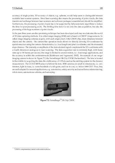
7.2 Outlook 133accuracy <strong>of</strong> single points, 3D accuracy <strong>of</strong> objects, e.g. spheres, would help users to distinguish betweenavailable laser scannersystems. Since laser scanning also means the processing <strong>of</strong> point clouds, the datatransfer <strong>and</strong> exchange between laser scanners <strong>and</strong> s<strong>of</strong>tware packages is essential <strong>and</strong> should be simplified.Furthermore, the processing <strong>of</strong> point clouds has to be supported by fully-automatic algorithmsthe time for post-processing work. The limiting time factor is not only the data acquisition,processing <strong>of</strong> the huge numbers <strong>of</strong> point clouds.In the past three years another promising technique has been developed <strong>and</strong> mayto reducebut also therevolutionise the world<strong>of</strong> 3D data capturing methods. It is called range-imaging (RIM) <strong>and</strong> is based on CMOS1 imagecalled range-imaging cameras acquire, with each single pixel <strong>of</strong> the CMOS chip, slopeobjects<strong>and</strong> the camera. Thesensors. Sodistances betweencamera-like operation mode allows for directly deriving 3D coordinates byspatial resection using the camera characteristics, i.e. focal length <strong>and</strong> pixel coordinates, <strong>and</strong> the measuredslope distance. The intensity or amplitude <strong>of</strong> the demodulated signal complementthe 3D coordinates witha fourth dimension analogous to laser scanning. The data acquisition rate is extremely high,rates up to 50 frames per second, the range is limited to several meters, i.e.with frameclose-range applications, <strong>and</strong>the accuracy is within the centimeter-scale [Kahlmann <strong>and</strong> Ingens<strong>and</strong>, 2005]. An example <strong>of</strong> one rangeimagingcamera is shown in Figure 7.2, the SwissRanger SR-2 by CSEM (Switzerl<strong>and</strong>). The lens is locatedin the middle for acquiring the data, the visible array <strong>of</strong> LEDs is used as the emitting system for the distancemeasurement. The CCD/CMOS sensor is behind the lens. RIM cameras are small in dimensions, i.e. cen¬timeters, light in mass, i.e. some hundreds <strong>of</strong> a kilogram, <strong>and</strong> low in cost, i.e. below 1000 CHE Thus, theyare well-adapted for several applications, e.g. automotive, safety, security <strong>and</strong> surveillance, telemonitoring,robot vision, autonomous vehicles, <strong>and</strong> surveying.Figure 7.2: SwissRangerSR-2 by CSEM.CMOS: complementary metal-oxide-semiconductor