

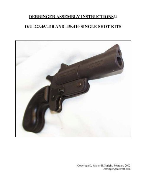
DERRINGER ASSEMBLY INSTRUCTIONSï O/U .22/.45/.410 AND .45/.410 ...
DERRINGER ASSEMBLY INSTRUCTIONSï O/U .22/.45/.410 AND .45/.410 ...
DERRINGER ASSEMBLY INSTRUCTIONSï O/U .22/.45/.410 AND .45/.410 ...
- No tags were found...

You also want an ePaper? Increase the reach of your titles
YUMPU automatically turns print PDFs into web optimized ePapers that Google loves.
azing. The actual brazing procedure is only 10% of the overall process. Be sure to useproper welding safety precautions like having a fire extinguisher and a pail of water andNOTHING flammable nearby. At the very least, wear welding-rated eye protection andwelding gloves (as well as any other welding protection you may have). I found Harris“Stay-Silv®” White Brazing Flux and 3/32 White Flux Coated Low Fuming Bronze rods tobe excellent choices with an Oxy-Acetylene Torch.11. Braze the Breech Face to both sides of the Side Plates. Braze only the back side of theBreech Face where it touches each of the Side Plates (not the lower part where theprotrusion exists or where the Breech Face meets the horizontal section of the Side Plates).Be careful here. The materials will be VERY, VERY hot (literally red hot), during brazingand immediately after. Confirm that the alignment has remained exactly as originallyestablished. Wait until the brazing components have returned to room temperature beforecontinuing with the assembly process since some of the remaining parts can be damaged byexcessive heat.Remove the clamp and ensure that the brazed parts are tight and cannot be separated evenwith considerable hand pressure. Do NOT push with too much pressure inward on the SidePlates or you may inadvertently bend the lower parts and cause misalignment (especiallyafter so much effort getting it right in the first place).If problems exist, you will need to decide whether to re-braze or to purchase or make areplacement Breech Face and Side Plates. Remember, this is a firearm. Poor assembly cancause subsequent assembly problems and can quite possibly be dangerous. If the brazingprocess results in excess material, use a flat file or a rotary tool to remove the excess. Becareful not to remove any of the actual Breech Face or Side Plate. If this process results inbreaking the brazing, then you will need to restart. Don’t be too upset. Since simple filingexerts much less pressure and force than a fired shell, it should NOT break the brazing. It ismuch better to know now rather than when firing the first shot that the brazing was faulty. Ifre-brazing is necessary, be certain to clean the surfaces MORE thoroughly than before,especially since they will now also be crusty, dirty, and covered with burned flux and excessbrazing material.12. If you want to paint the plates, now is a good time as long as the parts have cooled to roomtemperature. Be certain to use paint that can withstand considerable heat (similar to that usedfor an oven or an outdoor grill). I found a pint of black (7778) Rust-Oleum Specialty HighHeat far more than adequate – but that was the smallest quantity available. Use as thin a coatas possible. Do not double-coat the assembly, as one coat should be sufficient and you donot want to change the alignment or cause part movement difficulties with paint buildup. Besure to remove all drips before the paint dries. Finally, allow the paint to dry at least 24hours before continuing the process. The paint may interfere with the motion of othercomponents (e.g., the Barrel Latch Knob, Safety Shield and especially the Safety Pin), so beprepared to sand some away if necessary. You might be required to repaint some minorareas after finalizing the assembly process. In any event, being a firearm, functionalityshould take precedence over beauty.7
13. For me, brazing was the toughest part. The remaining assembly was comparably MUCHeasier. Insert the Spacer (16) between the Side Plates and put the Left and Right Grips (16)on the outside of the Side plates. Do NOT screw the Grip assembly together yet but hold ittightly together.14. Now place the Hammer Plunger (7) into the Hammer Spring (6). Insert it between the SidePlates just in front of the Spacer and under the front of the Side Grips with the HammerPlunger on top. Notice two rectangular holes on the Side Plates. The Hammer Plungershould fit INSIDE and between the tops of these holes. This can be a bit tricky. It is NOTsufficient that the Side Grips only hold it in place – the top edge of the Hammer PlungerMUST be held between the holes in the Side Plates. As you proceed you will need to reducethe hand pressure on the Side Grips enough (but only enough) to allow the top of theHammer Plunger to fit between them.Given the fact that the rectangular holes in the Side Plates are recessed below the tops of theSide Grips, try using a flat-faced punch or something similar to push it down into place. Donot press too hard since the spring eventually rests on the plastic part of the Spacer and itcan be broken. You only need to press it until the top of the Hammer Plunger fits into thetop of the rectangular holes of each of the Side Places. Once it is in place the Side Gripsshould close tightly together. (NOTE: Be careful here, both to avoid breaking the Spacer andfor the following reason. As you push down on the Hammer Plunger, you will becompressing the Hammer Spring. If you lose grip or the punch slides off the HammerPlunger, the Hammer Spring and Hammer Plunger can easily separately launch across theroom and take some time to find. This happened to me twice.)Holding the Side Grips tightly with one hand, screw the assembly together using the GripScrew (15) – but not TOO tightly since The Grips and Spacer are plastic, not steel. The partsshould fit with no spaces between them. If there is a visible gap, then the most likelyproblems are a misalignment in the Breech Face and Side Plates, an improper HammerPlunger and Hammer Spring insertion, or an inadequately tight Grip Screw. First, recheckthe alignment of the Hammer Plunger and Hammer Spring and correct it if necessary. If thisdoes not resolve the gap, then try loosening and then re-tightening the Grip Screw. If theGrip Screw is tight <strong>AND</strong> the Hammer Plunger and Hammer Spring are correctly inserted,then the brazing is misaligned. Go back to step 8 for instructions on how to correct thisproblem (if possible). If there is no gap or an almost invisible gap, then use the flat-facedpunch or something similar to confirm that the Hammer Plunger and Hammer Spring areproperly seated. If not, remove the Grip Screw and restart the procedure in this paragraph. Ifso, confirm that the hole in the Breech Face remains centered between the Side Plates. Ifvalidated, then the first test of a correctly aligned Breech Face and Side Plates has beensuccessful. CONGRATULATIONS! If not, remember that proper preparation is 90% ofsuccessful brazing. Don’t rush through the second brazing in annoyance if the firstattempt(s) did not work. Take a deep breath and wait until you calm down.15. Obtain a paper clip and fold it open to create a thin rod. Hold the Trigger Spring (4) by itslong protruding tips, with the connecting piece to the front and insert it between and near thelower protruding section of the Side Plates. Align both sides of the circular hole in theTrigger Spring with the holes in the Side Plates where the Trigger will go. Now insert theTrigger (1). Hold it by the base with the protruding upper section of the Trigger to the front,between the protruding tips of the Trigger Spring but below and behind the connecting piece8
with the hole in the Trigger aligned with the holes in the Trigger Spring and the Side Plates.This may take some time. Once you can see parts of all three holes (the two in the springand the one in the Trigger) through the holes in the Side Plates, insert the point of theopened paper clip through all of the five holes and run it in a circle to help align them asclosely as possible. Save the paper clip.Insert the thin end of the Trigger Pin (2) through the hole in the left Side Plate and push itthrough until it protrudes through the right Side Plate and the thick end is flat and tightagainst the left Side Plate. It may take a few attempts to get this right. Once this is complete,secure the Trigger Pin in place by attaching the Safety Shield (13) with the indented sectionof the Safety Shield pointing down and to the back and then sliding the indented sectionCOMPLETELY down and through the protruding and recessed notch at the tip of theTrigger Pin. If done correctly, you should be unable to remove the Trigger Pin from the leftside of the assembly but able to swing the Safety Shield counter-clockwise towards the SidePlates where the Barrel will go and align the round hole in the Safety Shield with the ovalBarrel Latch hole in the Side Plate. Furthermore, both of the long protruding tips of theTrigger Spring <strong>AND</strong> the connecting piece of the Trigger Spring should be to the front of theassembly and the Trigger. If the protruding tips of the Trigger Spring are behind the Trigger,then use the paper clip to confirm that they can be easily moved in front of the Trigger. Thisis most easily viewed from beneath. Put the assembly to the side for the moment. If themovement of the Safety Shield is difficult, it may also be due to the paint so sanding awaysome of the paint may satisfactorily improve movement.16. Now you need to attach one of the Barrel Latch Knobs (10) to the Barrel Latch Pin (11).These parts fit VERY tightly and cannot be attached by hand. The flat part of the BarrelLatch Knob should face the Barrel Latch Pin. Hold one tip of the Barrel Latch Pin on a flatmetal base (such as an anvil or the base next to a bench vise) while simultaneously holdingthe Barrel Latch Knob with the flat part down and the hole centered over the Barrel LatchPin. Using a flat-faced hammer (to preserve the flat integrity of the part of the Barrel LatchKnob to be struck), lightly tap the Barrel Latch Knob until it is seated sufficiently on theBarrel Latch Pin to stay without being held. (NOTE: While the intuitive procedure would beto hammer the Barrel Latch Pin into the Barrel Latch Knob, this is not done here to preservethe flat and unblemished integrity of the other tip of the Barrel Latch Pin. The other side ofthe Barrel Latch Pin will need to be in perfect condition when the time comes to attach theother Barrel Latch Knob and this is more likely if it is not subjected to repeated hammerblows.)Adjust the Barrel Latch Knob until it is perpendicular to the Barrel Latch Pin. If the BarrelLatch Knob separates from the Barrel Latch Pin, lightly tap the Barrel Latch Knob backuntil it is secure. If you have trouble with this, try clamping the base of the pin with a pair offorceps. Then hold the forceps down with the edge of the hand that will not be holding thehammer while holding the Barrel Latch Knob steady on the edges with two fingers.When satisfied that the alignment is reasonably good, holding the Barrel Latch Pin uprightand steady, strike the Barrel Latch Knob with a bit more force being certain to keep theBarrel Latch Pin perpendicular to the flat metal base. Check the alignment frequently.Continue until the tip of the Barrel Latch Pin is even with the outside and pyramid-like tip ofthe Barrel Latch Knob. When complete, the flat part of the Barrel Latch Knob should beperpendicular to the Barrel Latch Pin. If you used a clamp or forceps, remove it at this point.9
17. Returning to the main assembly, use the tip of the opened paper clip and insert it into the topof the Side Plates over the oval holes through which the Barrel Latch Pin will be inserted.Using the paper clip tip, find BOTH of the long ends of the Trigger Spring and move themto the upper back of the oval holes in the Side Plates so that there is enough space for theBarrel Latch Pin to fit beneath them. The long ends of the Trigger Spring (4) are eitherhanging beneath the Side Plate and need to be pushed up into the barrel latch hole area, arealready visible in the barrel latch hole, or are, lucky you, already slightly above the barrellatch hole. Holding the Barrel Latch Knob (with the Barrel Latch Pin already attached),insert the Barrel Latch Pin through the left oval hole in the Side Plate and continue until itpasses through the oval hole on the right Side Plate. Once the Barrel Latch Pin has passedthrough both of the Side Plates, hold the attached Barrel Latch Knob (10) tightly against theSide Plate and far enough to the back so that the Trigger Spring (4) cannot slip beneath theBarrel Latch Pin. Confirm that both of the long ends of the Trigger Spring (4) remain aboveand to the back of the Barrel Latch Pin. If this is not true, pull out the Barrel Latch Pin andrestart this step. While maintaining pressure on the attached Barrel Latch Knob, remove thepaper clip.18. Retract the Barrel Latch Knob just enough to allow the Barrel Latch Pin to be only slightlyrecessed but still touching the edge of the right Side Plate. Move the Safety Shield so thatthe round hole is aligned with the Barrel Latch Pin (you may need to move the Barrel LatchKnob and Barrel Latch Pin assembly to accomplish this) and push the Barrel Latch Pinthrough the hole in the Safety Shield. Maintain pressure on the Barrel Latch Knob to ensurethat the Barrel Latch Pin remains visible and does not retract so far through the right SidePlate to cause the Trigger Spring to slip under the Barrel Latch Pin or to allow the SafetyShield to fall. Reconfirm that both of the long ends of the Trigger Spring remain above andto the left of the Barrel Latch Pin. If this is not true, pull out the Barrel Latch Pin and goback to step 17.19. Holding the Barrel Latch Knob already inserted through the barrel latch holes secure againstthe Side Plate, place the tip of that Barrel Latch Knob on a secure metal surface (e.g., ananvil or the device used during the attachment of the first Barrel Latch Knob) and retainpressure to keep it in place. You may need to hold it at an angle or near the edge since theattached Barrel Latch Knob will not remain secure against the surface if the assembly ismerely placed “as is” on it. I found that merely moving the Grips off the flat surface wassufficient. Reconfirm that both of the long ends of the Trigger Spring (4) remain above andto the left of the Barrel Latch Pin and that the Barrel Latch Pin protrudes through the hole inthe Safety Shield. If this is not true, pull out the Barrel Latch Pin and restart step 17.20. (NOTE: Attaching the second Barrel Latch Knob while retaining the ability of theSafety Shield to move freely and easily is the next CRUCIAL part of the assembly. Ifyou tap too hard and secure it too tightly, it will be difficult if not impossible to resolvethe situation without damaging one or both of the Barrel Latch Knobs.) Whilemaintaining downward pressure on the part of the derringer containing the attached BarrelLatch Knob, place the flat part of the remaining Barrel Latch Knob onto the Barrel LatchPin. First, place it on by hand trying to align it as close to perpendicular to the Barrel LatchPin as possible. Using a flat hammer, lightly tap the second Barrel Latch Knob until it ismore secure. Adjust the alignment between each tap until it is secure. Then continue to tap10
ut now both ensure that it remains perpendicular <strong>AND</strong> that the Safety Shield continues tomove freely and easily.Continue tapping until the Barrel Latch Knob is securely attached to the Barrel Latch Pinwhile the Safety Shield continues to move freely and easily. If you apply too much pressure,you will have difficulty moving the Barrel Latch Knobs all the way forward and back. If thisis the case, first try moving them back and forth many times to see if this will solve theproblem. If not, then try sanding away all of the paint on both sides of the Side Plates.Finally, try inserting a micro screwdriver head between the Barrel Latch Knob and the SidePlate on the side opposite the Safety Shield and VERY slightly loosen the connection. If youmust do it more than once, retain alignment by adjusting in the following order: top, bottom,front and back. Recheck the movement between each adjustment, as you do not want toexcessively loosen the connection or accidentally force the Barrel Latch Knob off the BarrelLatch Pin entirely.If the Barrel Latch Knob will not stay in place (because it was forced off the Barrel LatchPin or because the adjustment loosened it too much), try hammering it back in place aspreviously described. If this does not work, you may need to carefully braze the tip of theloose Barrel Latch Knob once it is properly aligned and the movement is correct. This is avery tricky procedure given the extent of the assembly and should be attempted only if youfeel VERY comfortable with brazing. Given my difficulty with the original brazing, I wouldnot attempt this much more complex and detailed brazing. Alternatively, you may need areplacement Barrel Latch Knob that will be difficult to obtain (unless the vendor from whomyou obtained the kit is willing to sell you one), the assistance of a welding expert (who maybe hesitant or unwilling to work on a firearm), or the assistance of a gunsmith (where youmay encounter legal and regulatory complications). To avoid these problems, do it gentlyand correctly the first time! Once done, you should be able to move the Barrel Latch Knobassembly forward and backward in the barrel latch slot. The assembly is now almostcomplete. CONGRATULATIONS!21. Attach the Barrel (8) with the hole at the bottom of the Barrel to the front of the assemblyand aligned with and between the holes in the Side Plates. Insert the thin end of the BarrelPin (9) through the right Side Plate hole and push until it is completely through both SidePlates and the hole in the Barrel. Lower the Barrel onto the Side Plates. The Barrel LatchKnobs should move back as the Barrel contacts the Barrel Latch Pin and locks in place. Ifthis does not occur, then move the Barrel Latch Knobs as far back as possible and repeat theattempt. Once the Barrel contacts the Side Plates, hold the Barrel down and push forward onthe Barrel Latch Knobs. This should lock the Barrel in place.If this doesn’t work after several attempts, and only as a LAST RESORT, you may try usinga rotary tool or round file to shave away some of the metal on the recessed, back part of theBarrel where the Barrel Latch Pin goes. Work slowly and test the alignment frequently toavoid shaving away too much of the Barrel. I needed to do this during one assembly and itsolved the problem most effectively.Once the Barrel is properly aligned and appropriately locks, you may attach the Barrel Pin EClip (12) around the protruding and thin end of the Barrel Pin. Place the open part of theClip against the Barrel Pin and PUSH. This may take some effort and most likely cannot bedone by hand. You may need to use a screwdriver or forceps to force the Barrel Pin E Clip11
onto the Barrel Pin. If you break the pin, a replacement can be obtained at a hardware store(but take the Barrel Pin with you to get the correct size)<strong>.22</strong>. At some point during this step, you’ll probably wish you had three hands! Place the Hammer(5) in front of the Grips and behind the Breech Face. The flat part at the base of the Hammershould rest on top of the Hammer Plunger and the firing pin part of the Hammer should facethe Breech Face. To secure the Hammer, pull and hold the Trigger as far back as it will go(this is a critical step even if it doesn’t seem to make sense unless you try to attach theHammer without doing so) and press down on the Hammer until its hole is aligned with theone remaining hole through which the Safety Pin (3) will be inserted. This may take sometime and effort since it will require some compression of the Hammer Spring. If necessary,move the Barrel Latch Knobs forward to allow the square end of the Safety Pin to fit into thesquare hole on the right Side Plate. Insert the round end of the Safety Pin into the squarehole on the right Side Plate. Continue pushing until the round part of the Safety Pinprotrudes through the left Side Plate and only a small part of the square part remains on theright Side Plate. You may need to move the Hammer back and forth and up and downvigorously to succeed.23. Push in square end of the Safety Pin until the round part protrudes through the left Side Plateand continue pushing the square end of the Safety Pin until it is slightly recessed into theSide Plate. Jiggle the Hammer until this is accomplished. Make sure the Safety Shield canretract over the Safety Pin. This took me quite a few attempts. You may need to repeat theprior step several times since aligning the hidden flat part of the hole in the Barrel with thenow hidden flat part of the Safety Pin can be difficult. Once done, pull back on the BarrelLatch Knobs and close the Barrel. This should lock the Barrel in Place. If not, push forwardon the Barrel Latch Knobs and the Barrel will now lock in position. Holding the Grips, useyour thumb to pull back on the Hammer. It should be locked in place and immobile (i.e.,unable to cock). Test by pulling the Trigger. It should have no effect. The safety is in effectand functional.24. Before proceeding with this step, CONFIRM THAT THE <strong>DERRINGER</strong> ISUNLOADED! (NOTE: No ammunition should be present or loaded into the derringer – Imention it again since this procedure would result in gunfire if it were loaded.) Move theBarrel Latch Knobs forward until the square part of the Safety Pin is free to move throughthe right Side Plate. Push on the round part of the Safety Pin until the Square section of theSafety Pin protrudes through the right Side Plate enough to prevent the Safety Shield frommoving backward and perhaps even a bit more (but not so much that the round part of theSafety Pin retracts into the left Side Plate). You will once again need to jiggle the Hammer.Holding the Grips, use your thumb to pull back on the Hammer. It should retract and lock inthe cocked position. Pull the Trigger. The Hammer will forcefully strike the Breech Face. Ifyou cannot move the Safety Pin by hand with minimal effort, remove the Safety Pin and tryre-filing each of the square holes in the Side Plates. Be sure to maintain a square hole bylightly filing EACH of the 4 sides ONCE and then retry inserting the Safety Pin. Continueuntil the square part of the Safety Pin fits a bit more loosely through the hole. Do NOTexcessively file the hole on the Side Plate – the fit should be snug so each side of the SafetyPin can be pushed back and forth through its appropriate Side Plate with only fingerpressure. Do not push so hard on the round part of the Safety Pin that it recesses into the leftSide Plate since it has not yet been secured. If the Safety Pin recesses so far into the SidePlate that it cannot be pushed back out, return to step 22 to reset the Safety Pin.12
Once you have confirmed that the derringer can be fired and rendered safe (test both severaltimes), attach the Safety E Clip (14). (NOTE: With the O/U Derringer, test this several timeswith the firing pin in both positions as described in the first two sentences of step 25.) Thiswill prevent the round part of the Safety Pin from retracting too far into the Side Plate whilethe Trigger itself prevents the same problem from the other direction. Place the open part ofthe Clip against the grooved notch at the end of the round part of the Safety Pin and PUSH.This may take some effort and most likely cannot be done by hand. You may need to use ascrewdriver or forceps to force the Safety Pin E Clip onto the Safety Pin. If you break thepin, a replacement can be obtained at a hardware store (but take the Safety Pin with you toget the correct size).25. With the O/U Derringer 22/45/410 kit, to fire the <strong>.22</strong> LR round, pull back the Hammer andpush UP the firing pin part on the front part of the Hammer. To fire the <strong>.410</strong> shotgun shell or<strong>.45</strong> Long Colt shell, pull back the Hammer and push DOWN the firing pin part on the frontpart of the Hammer. WITHOUT LOADING THE <strong>DERRINGER</strong>, test fire both upper andlower chambers several times. In both cases, open the Barrel after pulling the trigger andensure that the firing pin part of the Hammer protrudes through the Breech Face atapproximately the point where the selected shell would be located. With the 45/410 kit,there is nothing to adjust on the Hammer; however, you should still test fire it several timesto ensure that the firing pin part of the Hammer protrudes through the Breech Face atapproximately the point where the shell would be located.26. THAT’S IT! You have now successfully built your own fully functional Over/Under22/45/410 Derringer or your 45/410 Derringer!CONGRATULATIONS!13
On the next few pages, I would like to provide you with some cautions and recommendations:a. The safety works differently than on most pistols. Become accustomed to itBEFORE you insert any ammunition into the derringer. In effect, BE CAREFUL!b. If you are seeking a holster for this derringer, try the Derringer Holster by San PedroSaddlery, shown below and usually available for auction at www.gunbroker.com orwww.auctionarms.com.This image was obtained from a listing by MrBisley at www.gunbroker.com.c. Use only <strong>.45</strong> Long Colt (NOT <strong>.45</strong> ACP) or <strong>.410</strong> Shotgun Shells in the lower chamberof an over/under combination or in the single chamber of a <strong>.45</strong>/<strong>.410</strong> Derringer. Donot use any other type of ammunition even if it “appears” to fit since the chamber ofthe barrel is specifically designed for only these two types of ammunition. Any othertype might cause problems due to such complications as differences in ballisticpressures, primer location, the need for a longer and/or rifled barrel, etc. Someproblems may result in a simple hangfire, misfire or render the derringer unable tofire. Other problems may result in serious complications including but not limited toblowing apart or destroying the barrel, breaking the firing pin, fragmenting thebullet, or significantly altering the expected pattern, direction or diameter of the shot.i. If you make your own ammunition, be sure to use the exact ST<strong>AND</strong>ARDspecifications for the above-referenced shells. Do NOT exceed the charge,use different primers, or include exotic shell contents. This derringer is NOTdesigned to accommodate such variances and its response to suchexperimentation cannot be predicted. This is a firearm. BE SAFE <strong>AND</strong>DON’T TAKE CHANCES!ii. Due to the style of the derringer and the slope of the handle, the recoil will bea bit more and somewhat different than you might otherwise expect from anequivalent shell fired with a more conventional pistol or shotgun. A word tothe wise should be sufficient.14
iii. While the <strong>.45</strong>/<strong>.410</strong> chamber can accommodate 3” shells, my personalammunition preferences (all available for reasonable prices fromhttp://www.cheaperthandirt.com) are:(1) Sellier & Bellot <strong>.410</strong>gauge 3shot 000 Buck Shot in a 2.5” shell.(2) Remington <strong>.410</strong> gauge 1/5 oz. Slug in a 2.5” shell.(3) Winchester Super-X Centerfire Pistol/Revolver Cartridges, <strong>.45</strong>Long Colt, 225 Grains, Silvertip Hollow Point.d. Use only <strong>.22</strong> Long Rifle shells in the upper barrel of an over/under combination.(Although a <strong>.22</strong> Short would work, I wouldn’t since better options are available.) Donot use any other types of ammunition for the same reasons noted in c. above.iv. If you make your own ammunition, be sure to use the exact specifications forthe above-referenced shells. Do NOT exceed the charge, use differentprimers, or use exotic shell contents. This derringer is NOT designed toaccommodate such variances and its response to such experimentation cannotbe predicted. This is a firearm. BE SAFE <strong>AND</strong> DON’T TAKE CHANCES!v. Don’t be confused by the size of this bullet or the concept that “it’s only a<strong>.22</strong>.” While it admittedly has limited value for defense, some have a range of1.5 miles!vi. My personal ammunition preferences for this chamber are:(1) CCI/Speer <strong>.22</strong> Long Rifle Hollow Point Mini Mag Ammunition.(2) <strong>.22</strong> Long Rifle Blue Tip Incendiary Ammo (usually available atwww.gunbroker.com). These make a significant impression and canbe great fun but they are admittedly expensive! Still, their uniquenature may also be more effective in ending a tactical situationwithout needing the lower chamber. Nevertheless, remember thatthey are incendiary shells so do not fire them into anythingflammable including dry leaves or wooden targets. As the sayinggoes, only YOU can prevent forest (or house) fires so as always,use good sense. Show respect for and consider the implications ofthe weapon and ammunition you use AT ALL TIMES!e. While you were able to avoid the FFL requirements by obtaining partially completedkits from separate sources, once the derringer is completed everything changes. Oncethis derringer is completed, you CANNOT sell it unless you hold a Federal Class IIFFL and it is legal to do so in your location. Some states have special rules at gunshows. Some states or counties do not permit the sale of this derringer under anycircumstances – even by licensees who can otherwise sell even Class 3 weapons!f. Once the derringer is completed, TREAT IT JUST LIKE ANY OTHER FIREARMYOU OWN! Use a trigger lock. Keep it in a locked safe. Keep it away from children.Do not carry it unless you have a permit to do so. Keep the ammunition dry. If you15
are carrying it loaded, put on the safety and CONFIRM it by gently trying to pullback on the hammer. If the hammer cocks, then hold the hammer tightly, pull theTrigger, and release the Hammer SLOWLY. Proceed once again to set the safety. Ineffect, from a safety and legal perspective, treat it like you would an expensiveautomatic pistol or revolver. The fact that you made it makes no difference ONCE ITIS MADE! Even if you omit certain parts to make it non-functional and can prove itif necessary, it can still be considered a firearm under certain conditions by theauthorities – especially since September 11.g. If you ever have the misfortune to need the Derringer in a tactical situation, youdon’t want it to be the first time you’ve fired it! Go to a firing range and practicewith your new Derringer. I hesitated including this step since at least one practicesession with your new handgun is inevitable given all the work you put into makingit. Still, as you’ve no doubt learned by this point, I have no problem with being toodetailed. ☺ Test both chambers of the O/U model. Use EVERY type of ammunitionthat you intend to fire in the Derringer after obtaining approval from the rangeofficer – especially if you purchased the incendiary <strong>.22</strong> shells. If possible, confirmthat the range will permit firing all of your ammunition before driving there. Mostindoor ranges and some outdoor ranges only allow ammunition purchased at therange, so be sure they have the same ammunition you have purchased in stock beforeyou make the trip. It may even be preferable to try various brands and typesammunition from their stock before making your own personal choices (beingcertain to consider the ammunition limitations of the derringer). Range ammunitionis generally more expensive than similar ammunition obtained from other sources. Ifyou identify a personal preference, write down the specifics and seek the ammunitionfrom a less expensive vendor (e.g., www.cheaperthandirt.com,www.sportsmansguide.com or one of the gun-related auction sites). You may alsowant to join an organization that provides pistol and shotgun ranges. Consider theIzaak Walton League of America. The link to my particular chapter ishttp://www.iwla-rockville.com/.GOOD LUCK <strong>AND</strong> BEST WISHES! If you have any questions not covered in these instructions,please feel free to send me an email at Derringer@farcroft.com. Since these instructions can be usedwith minor modifications to make several different derringers, be sure to include which version wewill be discussing.16
PARTS DIAGRAM(1) Trigger(2) Trigger Pin(3) Safety Pin(4) Trigger Spring(5) Hammer(6) Hammer Spring(7) Hammer Plunger(8) Barrel(9) Barrel Pin(10) Barrel Latch Knob – 2 ea.(11) Barrel Latch Pin(12) Barrel Pin E Clip(13) Safety Shield(14) Safety E Clip(15) Grip Screw(16) Left Grip, Right Grip & Spacer – 1 ea.(17) Breech Face(18) Side Plate – 2 ea.TOOLSBucket of waterFire extinguisherWelding-rated safety gogglesWelding glovesLarge and small flat fileRotary tool (optional but helpful)DegreaserFlat-faced screwdriver Paper clipLarge heat resistant vise gripFlat metal base (anvil bench vise base)ForcepsSandpaperHarris “Stay-Silv®” White Brazing Flux3/32 White Flux Coated Low Fuming BronzerodsOxy-Acetylene TorchFlat-faced hammerFlat-faced punch or something similarBlack (7778) Rust-Oleum Specialty High Heat(optional)Round fileFlat-faced screwdriver17


