Owner's Manual - Emerson Fans
Owner's Manual - Emerson Fans
Owner's Manual - Emerson Fans

You also want an ePaper? Increase the reach of your titles
YUMPU automatically turns print PDFs into web optimized ePapers that Google loves.
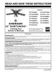
READ AND SAVE THESE INSTRUCTIONSBlades & Downrod Kit Sold SeparatelyTwo Person Installation RequiredNet Weight: 44.8 Lbs.ST CROIX Damp LocationCeiling Fan<strong>Owner's</strong> <strong>Manual</strong>Model NumbersCF3300APCF3300ORHLIMITED WARRANTYWhat The Warranty Covers:This warranty covers the motor and the other components and accessories of your <strong>Emerson</strong> ceiling fan against all defects in workmanship and materials.You must be the original purchaser or user of the product to be covered.What The Period Of Coverage Is:As it applies to the motor, this warranty will last for a lifetime of your ceiling fan. All other components and accessories arecovered by this warranty for one year from the date you purchased your ceiling fan. ANY IMPLIED WARRANTY OF MERCHANTABILITY OR FITNESS FOR APARTICULAR PURPOSE, MADE WITH RESPECT TO COMPONENTS AND ACCESSORIES IS ALSO LIMITED TO ONE YEAR.What Will <strong>Emerson</strong> Electric Co. Do To Correct Problems:<strong>Emerson</strong> Electric Co. will replace a defective <strong>Emerson</strong> Air Comfort Ceiling Fan motor, blade, component or other accessory at no charge to you. If repair ofthe motor or blades is not practical or possible within a reasonable time and no replacement can be provided, <strong>Emerson</strong> will refund the actual purchase priceof your fan. WE WILL SHIP THE REPAIRED PRODUCT OR REPLACEMENT TO YOU AT NO CHARGE, BUT YOU ARE RESPONSIBLE FOR ALL COSTS ORREMOVAL, REINSTALLATION AND SHIPPING OF THE PRODUCT TO EMERSON ELECTRIC CO.How Can You Get Service:YOU MUST HAVE PROOF OF YOUR PURCHASE OF THE CEILING FAN TO OBTAIN LIMITED WARRANTY SERVICE. KEEP YOUR RECEIPT OR OTHER PROOFOF PURCHASE. You can return the product to our factory or to your nearest authorized service center.• To return the product to the factory, obtain a return authorization and service identification tag by writing to Air Comfort Products, Division of <strong>Emerson</strong>Electric Co., 8100 W. Florissant Ave., St. Louis, MO 63136. Include all model numbers shown on the product with your request.• To return the product to an authorized service center, call 1-800-654-3545 for the address of the nearest authorized service center.You will be responsible for all insurance, freight or other transportation charges to our factory or authorized service center. Your <strong>Emerson</strong> Air ComfortCeiling Fan should be properly packed to avoid damage in transit since we will not be responsible for any such damage.What Is Not Covered:The glass globes and light bulbs of your ceiling fan are not covered by this warranty. This warranty also does not cover any defects, malfunctions or failurescaused by:• Repairs by persons not authorized by <strong>Emerson</strong> Electric Co.,• Use of parts or accessories not authorized by <strong>Emerson</strong> Electric Co.,• Mishandling, improper installation, modifications or damage to your ceiling fan while in your possession, or• Unreasonable use, misuse, abuse, including failing to do reasonable and necessary maintenance, and normal wear and tear.Additionally, this warranty and any implied warranty of merchantability or fitness for a particular purpose are voided when:• The original purchaser or user ceases to own the product, or• The fan is moved from its original point of installation.This warranty is only valid within the 50 states of the United States and the District of Columbia. No other written or oral warranties apply, and no employee,agent, dealer or other person is authorized to give any warranties on behalf of <strong>Emerson</strong> Electric Co.REPAIR, REPLACEMENT OR A REFUND ARE THE EXCLUSIVE REMEDIES AVAILABLE UNDER THIS WARRANTY AND EMERSON IS NOT RESPONSIBLEFOR DAMAGES OF ANY KIND, INCLUDING INCIDENTAL AND CONSEQUENTIAL DAMAGES. Incidental damages include but are not limited to such damagesas loss of time and loss of use. Consequential damages include but are not limited to the cost of repairing or replacing other property which was damaged ifthis product does not work properly.How State Law Relates To The Warranty:Some states do not allow the exclusion or limitation of incidental or consequential damages so the above exclusion or limitation may not apply to you.This warranty gives you specific legal rights, and you may also have other rights which vary from state to state.Part No. F40BP73850000Form No. BP7385U.L. Model No.: CF3300
!WARNINGWARNING: To avoid fire, shock, and serious personal injury, follow these instructions.Safety Instructions1. Read your owner’s manual carefully and keep it for future reference.2. Before servicing or cleaning unit, switch power off at service panel and lock service paneldisconnecting means to prevent power from being switched on accidentally. When the servicedisconnecting means cannot be locked, securely fasten a warning device, such as a tag, to theservice panel.3. Be careful of the fan and blades when cleaning, painting, or working near the fan. Always turn offthe power to the ceiling fan before servicing.4. Do not put anything into the fan blades while they are turning.5. Do not operate reversing switch until fan blades have come to a complete stop.Additional Safety Instructions for Installation1. To avoid possible shock, be sure electricity is turned off at the fuse box before wiring, and do notoperate fan without blades.2. All wiring must be in accordance with the National Electrical Codes “ANSI/NFPA 70-1999” andLocal Electrical Codes. Use the National Electrical Code if Local Codes do not exist. The ceilingfan must be grounded as a precaution against possible electrical shock. Electrical installationshould be made or approved by a licensed electrician.3. The fan mounting bracket must be surely mounted and capable of reliably supporting at least 100lbs. Outlet boxes are not acceptable for fan support. See Page 6 of owner’s manual for supportrequirements. Consult a qualified electrician if in doubt.CAUTION: To reduce the risk of personal injury, mount the fan base to a ceiling joist or structuralmember using the hardware provided with your fan.WARNING: Support Directly from Building Structure.4. The fan must be mounted with the fan blades at least 7 feet from the floor to prevent accidentalcontact with the fan blades.5. Follow the recommended instructions for the proper method of wiring your ceiling fan. If you donot know enough about electrical wiring, have your fan installed by a licensed electrician.WARNING: To avoid fire, shock or injury, do not use an <strong>Emerson</strong> or any other brand of control notspecifically approved for this fan.WARNING: This product is designed to use only those parts supplied with this product and/or anyaccessories designated specifically for use with this product by <strong>Emerson</strong> Electric Co. Substitutionof parts or accessories not designated for use with this product by <strong>Emerson</strong> Electric Co. couldresult in personal injury or property damage.WARNING: To reduce the risk of personal injury, do not bend the blade flange when installing theblade flanges, balancing the blades or cleaning the fan. Do not insert foreign objects in betweenrotating fan blades.NOTE: This fan is suitable for use with solid-state speed controls.WARNING: To reduce the risk of fire or electric shock, this fan should only be used with fan speedcontrol SW22, manufactured by Rhine Electric Co., Ltd.WARNING: To reduce the risk of electrical shock, this fan must be installed with an isolatingwall control/switch.WARNING: To reduce the risk of fire, electric shock, and injury to persons, ceiling fan must beinstalled with fan blades and light kits that are marked to indicate the suitability with this model.Other blades and light kits can not be substituted.DATE CODE:The date code of this fan may be found on the box, stamped in ink on a white label.You should record this data above and keep it in a safe place for future use.2U.L. Model No.: CF3300
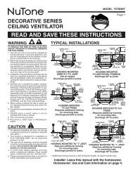
THIS FAN IS SUITABLE FOR DAMP LOCATIONSSUCH AS COVERED PORCHES, COVERED PATIOS, AND COVEREDDECKS...ANYWHERE THERE IS A ROOF OVERHEAD.Tools Needed for AssemblyOne Phillips head screwdriver One stepladderOne 1/4” blade screwdriver One wire stripperOne 5/16” open end wrench or pliers7/16”, 1/2” & 9/16” wrench or socket wrenchOne 1/4” drill bitMATERIALSWiring outlet box and box connectors must be of typerequired by the local code. The minimum wire wouldbe a 3-conductor (2-wire with ground) of followingsize:Installed Wire Length Wire Size A.W.G.Up to 50 ft. 1450-100 ft. 12!WARNINGBefore you assemble your ceiling fan, refer tosection on proper method of wiring your fan(page 8). If you feel you do not have enoughwiring knowledge or experience, have your faninstalled by a licensed electrician.Unpacking InstructionsFor your convenience, check-off boxes are provided next to each step. As each step is completed, place acheck mark in the box. This will insure that all steps have been completed and will be helpful in findingyour place should you be interrupted.!Do not install or use fan if any part is damagedor missing. Call Toll-Free:1-800-654-3545!WARNINGWARNINGThis product is designed to use only thoseparts supplied with this product and/or anyaccessories designated specifically for usewith this product by <strong>Emerson</strong> Electric Co.Substitution of parts or accessories notdesignated for use with this product by<strong>Emerson</strong> could result in personal injury orproperty damage.1. Check to see that you have received the followingparts:NOTE: If you are uncertain of part description,refer to exploded view illustration.NOTE: Blades and downrod kit sold separately.a. Fan assemblyb. Two fan motor coversc. One decorative downrod sleeved. One upper decorative downrod sleeveassemblye. One decorative strap ringf. One ceiling canopyg. Four right hand blade flangesh. Four left hand blade flangesi. One hanger ball/downrod extension assemblyj. One hanger bracket assemblyk. Eight blade medallionsl. One SW22 wall control with almond andwhite knobs3m.Mounting bracket bag, containing:1. One 3/8 x 2” lag bolt2. One 3/8 x 5” lag bolt3. Two 3/8” flat washers4. One brass barrel nut5. One bushing6. One ceiling support cable7. One 5/32 x 10mm phillips screwn. One hardware bag, containing:1. Five wire connectors2. One 1/16” hex wrench3. One clevis pin4. One hair pin clip5. Two threaded studs6. Two lockwashers7. Two knurled knobs8. Two 5/16-18 x 1/4” cup point setscrews9. One 3/16” hex wrencho. One flange assembly bag, containing:1. Seventeen #8-32 x 15mm flat head screwsp. Two blade assembly bags, each containing:1. Twenty-five #10-32 x 18mm oval headscrewsq. One downrod assembly bag, containing:1. Nine 1/4 x 10mm round head screwsNOTE: Keep all bags unopened until time ofassembly. Then place the parts from each looseparts bags in a small container to keep them frombeing lost. If any parts are missing, contact yourlocal retailer or catalog outlet for replacementbefore proceeding.2. Remove the fan assembly from the protectiveplastic bag. Place the fan assembly into the foampad with the downrod coupling facing up.The foam pad serves as a holder for the fan duringthe first stages of assembly.U.L. Model No.: CF3300
OFFF. DECORATIVESTRAP RINGD. UPPERDECORATIVEDOWNROD SLEEVEM. SW22WALLCONTROLA. FANASSEMBLYB. FAN MOTORCOVERS (2)H. RIGHT HANDBLADE FLANGES (4)I.LEFT HAND BLADEFLANGES (4)C. DECORATIVE DOWNRODSLEEVE ASSEMBLYM. MOUNTINGBRACKET BAGN. HARDWAREBAGL. BLADEMEDALLIONS (8)G. CEILINGCANOPYE. DOWNRODEXTENSIONK. HANGER BRACKETASSEMBLYJ. HANGER BALL/DOWNRODEXTENSIONO. FLANGEASSEMBLYBAGP. BLADEASSEMBLYBAGSQ. DOWNRODASSEMBLYBAGHow to Put Your Ceiling Fan Together1. Loosely install both 5/16-18 x 1/4” cup pointsetscrews (supplied) into the downrod coupling.Separate, untwist and unkink the three 80” motorleads and support wire. Route the motor lead wiresand support wire through the downrod extension.Align the clevis pin holes in the downrod extensionwith the holes in the downrod coupling. Install theclevis pin and secure with the hairpin clip(Figure 1). The clevis pin must go through theholes in the downrod coupling and the holes in thedownrod extension. Be sure to push the straight legof the hairpin clip through the hole near the end ofthe clevis pin until the curved portion of the hairpinclip snaps around the clevis pin. The hairpin clipmust be properly installed to prevent the clevis pinfrom working loose. Pull on the downrod extensionto make sure the clevis pin is properly installed.2. While pulling up on the downrod extension,securely tighten the two setscrews in the downrodcoupling using the 3/16” hex wrench (supplied).The setscrews must be tightened into the downrodextension. A loose extension downrod will resultwith fan assembly noise and vibration.! WARNINGIt is critical that the clevis pin in the downrodcoupling is properly installed and thesetscrews securely tightened. Failure to verifythat the pin and setscrews are properlyinstalled (as shown in Figure 1) could result inthe fan falling.4DOWNRODEXTENSIONCLEVIS PINDOWNRODCOUPLINGHAIRPINCLIP5/16-18 x 1/4" CUPPOINT SETSCREW (2)Figure 1NOTE: For ease of installation, loosely tape theends of the motor leads and the support wiretogether to route through downrod during faninstallation.3. Route the motor leads and support wire throughthe downrod (Figure 2).4. Securely attach the downrod to the downrodextension using the four 1/4 x 10mm round headscrews (supplied in the downrod assembly bag).The round head screws must be fully tightened intothe downrod extension. A loose downrod will resultwith fan assembly noise and vibration.U.L. Model No.: CF3300
DOWNRODDOWNRODEXTENSION1/4 x 10mm ROUNDHEAD SCREW (4)7. Route the motor lead wires and support wirethrough the upper decorative downrod sleeve andthe decorative strap ring (Figure 4). Careful not toscratch the downrod with the sleeve and ringduring installation.NOTE: Be careful not to scratch the downrodduring installation.8. Position the upper decorative downrod sleeve andthe decorative strap ring just above the decorativedownrod sleeve assembly during initial installation(Figure 4).DOWNRODFigure 25. Route the motor lead wires and support wirethrough the decorative downrod sleeve assembly.Carefully slide the decorative downrod sleeveassembly over the downrod and set firmly ondownrod coupling (Figure 3).6. Using the hex wrench (supplied), tighten the threesetscrews located at the top of the decorativedownrod sleeve assembly (Figure 3).NOTE: It is important that all setscrews aresecurely tightened and the decorative downrodsleeve assembly is secure. To not overtightensetscrews.DECORATIVESTRAP RINGUPPER DECORATIVEDOWNROD SLEEVEFigure 4DOWNRODSETSCREW (3)DOWNRODSETSCREW (3)NOTE: Apply masking tape to the entire edge ofthe ceiling canopy center hole to preventaccidental scratching of downrod surface(Figure 5).9. Route the motor lead wires and support wirethrough the ceiling canopy (Figure 5). Use extremecaution not to scratch the downrod with the ceilingcanopy during installation.CEILINGCANOPYDOWNRODDECORATIVEDOWNROD SLEEVEASSEMBLYMASKINGTAPEFigure 35Figure 5NOTE: Be careful not to scratch the downrodduring installation.U.L. Model No.: CF3300
10. Route the motor lead wires and support wirethrough the downrod extension and the hangerball (Figure 6).11. Securely attach the downrod to the downrodextension/hanger ball using the four 1/4 x 10mmround head screws (supplied in the downrodassembly bag) (Figure 6). The round head screwsmust be fully tightened into the downrodextension. A loose downrod will result with fanassembly noise and vibration.12. Be sure the hanger ball setscrews are securelytighten at this time.13. The fan comes with blue, black and white leadsthat are 80-inches long. Before installing the fan,measure up approximately 6 to 9-inches abovetop of hangerball/downrod assembly. Cut offexcess leads and strip back insulation 1/2-inchfrom end of leads.CEILINGCANOPYFigure 6HANGER BALLDOWNRODPINDOWNRODEXTENSIONSETSCREW14. Downrod assembly is now complete.1/4 x 10mm ROUNDHEAD SCREW (4)Your new ceiling fan will require a grounded electricalsupply line of 120 volts AC, 60 Hz, 15 amp circuit.!WARNINGTo avoid possible electrical shock, be sureelectricity is turned off at the main fuse boxbefore wiring.NOTE: If you are not sure if the outlet box isgrounded, contact a licensed electrician foradvise, as it must be grounded for safeoperation.Electrical RequirementsThe fan hanger bracket assembly shall be supporteddirectly from the supporting building structure. Anelectrical box is not acceptable for fan support. Thebuilding structure must be capable of supporting aload of at least 100 pounds. Consult a qualifiedprofessional to determine if your installation meets thestructural requirements.! WARNINGTo avoid fire or shock, follow all wiringinstructions carefully.Any electrical work not described in theseinstructions should be done or approved by alicensed electrician.How to Hang Your Ceiling FanIMPORTANTDo not attach fan blades to fan assembly until thefan assembly is securely installed to the ceiling.Hanging the fan with blades attached may resultin damage to the fan blades.CEILING!WARNINGThe fan must be hung with at least 7' ofclearance from floor to blades (Figure 7).ATLEAST7'! WARNINGSupport directly from building structure.Structure must be capable of reliablysupporting 100 pounds.Figure 7FLOOR6U.L. Model No.: CF3300
1. Securely attach the ceiling support wire to theceiling joist or structural member using the 3/8 x 2”hex lag bolt and flat washer. Drill a maximumdiameter 1/4” pilot hole into the supporting memberto prevent splitting or cracking. Install a washeronto the screw and insert the screw through one ofthe loops (Figure 8). Securely tighten the screwinto the structure.IMPORTANTDo not use any lubricant when installing the lagbolts.IMPORTANTThe pilot holes should be drilled no larger thanthe minor diameter of the mounting screwthreads, and at least 1-1/2 inches of the threadedpart of the mounting screw should be inchessecured into a structural wood joist to providesecure mounting.2. Drill a second maximum diameter 1/4” pilot hole upthrough the center of the electrical box (Figure 8).Install the hanger bracket assembly using 3/8 x 5”lag bolt and 3/8” flat washer. Route the electricalsupply wires through the opening provided on thehanger bracket. Do not completely tighten the lagbolt, leave it lose enough such that the hangerbracket assembly can be freely rotated against theelectrical box.3. Temporarily hang the ceiling fan assembly on thehanger bracket, be sure the hanger ball grooveengages the hanger bracket tab. Rotate the fanassembly and hanger bracket to the desiredorientation. Remove the fan assembly from thehanger bracket.4. Completely tighten the center lag bolt while holdingthe hanger bracket in the desired position.WOOD MEMBER(2" x 4" Approx.)CEILING JOIST! WARNINGHanger bracket must seat firmly against outletbox. If the outlet box is recessed, remove wallboard until bracket contacts box. If bracketand/or outlet box are not securely attached, thefan could wobble or fall.! WARNINGFailure to seat tab in groove could causedamage to electrical wires and possible shockor fire hazard.NOTE: If not done so already, carefully removethe masking tape applied to the motor leads andsupport wire to complete wiring.5. Position the motor lead wires and support cable onthe back side of the hanger bracket for finalconnection to the electrical supply wires.6. Carefully lift the fan assembly and seat thehangerball/downrod fan assembly into the hangerbracket. Be sure the groove in the hanger ball linesup with the tab on the hanger bracket(Figure 9).7. Install the end of the fan support cable through thecenter of the small brass bushing (supplied). Donot allow the bushing to slide down the cable andinto the downrod. Now pass the fan support cablethrough the loop provided on the free end of theceiling support cable previously installed into thebuilding structure. Next, pass the fan support cableback through the center of the small brass bushingin the opposite direction as the first pass. Pull asmuch cable as possible through the brass bushing(Figure 9A).SHORT CABLEASSEMBLYATTACHED TOCEILINGSMALL BRASSBARREL BUSHINGCEILINGCEILINGSUPPORT CABLEFigure 8OUTLET BOXHANGERBRACKETIMPORTANTIf you are installing your ceiling fan on a slopedceiling, the hanger bracket must be mounted withthe hanger ball opening facing up-slope.! WARNINGTo avoid possible fire or shock, do not pinchwires between the hanger ball/downrodassembly and hanger bracket.7HANGER BALL TABFigure 9ATTACH SUPPORT WIRETO CEILING SUPPORTWIREHANGER BALL/DOWNRODASSEMBLYU.L. Model No.: CF3300
8. Insert the fan cable through the hole of the largebrass barrel nut (supplied) and push it up the cableto within one inch of the small brass bushing. Passthe free end of the cable back through the largebrass barrel nut in the opposite direction andremove as much slack as possible.PASS THE FAN CABLETHROUGH THE LOOPAND BACK INTO THESMALL BARRELBUSHINGINSTALL LARGEBRASS BARREL NUTONTO THE CABLE9. Full tighten the 5/32 phillips head screw on thebrass barrel nut to secure the fan cable in position.Cut off and discard the excess fan cable protrudingfrom the brass barrel nut (Figure 9B).LOOP THE CABLEBACK INTO THELARGE BARRELNUTFAN CABLEFANCABLEFAN CABLELARGE BRASSBARREL NUTSMALLBARRELBUSHINGLARGE BRASSBARREL NUTFigure 9BFigure 9AHow to Wire Your Ceiling FanIf you feel that you do not have enough electricalwiring knowledge or experience, have your faninstalled by a licensed electrician.! WARNINGTo avoid possible electrical shock, be sureelectricity is turned off at the main fuse boxbefore wiring.NOTE: If you are not sure if the outlet box isgrounded, contact a licensed electrician foradvice, as it must be grounded for safeoperation.1. Connect the green grounding lead from the hangerball and the green grounding lead from the hangerbracket to the grounding conductor of supply (thismay be a bare wire or wire with green coloredinsulation). Securely connect wires with wireconnectors supplied. (Figure 10.)!WARNINGThis product is designed to use only thoseparts supplied with this product and/or anyaccessories designated specifically for usewith this product by <strong>Emerson</strong> Electric Co.Substitution of parts or accessories notdesignated for use with this product by<strong>Emerson</strong> Electric Co. could result in personalinjury or property damage.82. Securely connect the fan motor white wire to thesupply white (neutral) wire using wire connectorsupplied (Figure 10). Securely connect the fanmotor black wire to the supply black (hot) wireusing wire connector supplied (Figure 15). Theblue wire is for optional light kit accessory. Do notconnect the blue wire to the supply black wire. Capthe blue wire with a wire connector supplied. Afterconnections have been made, turn leads upwardand carefully push leads into the outlet box, withthe white and green leads on one side of the outletbox and the black and blue leads on the other sideof the outlet box.SUPPLYGROUNDWIRELISTEDWIRECONNECTOR (3)GREEN WIRE(GROUND) FROMHANGER BRACKETGREEN WIRE(GROUND) FROMHANGER BALLFigure 10BLACKFAN WIRESNOTE: CEILING COVEROMITTED FOR CLARITY.WHITE SUPPLY(NEUTRAL)WHITE FANWIREBLACK SUPPLY (HOT)THREADEDSTUD (2)! WARNINGCheck to see that all connections are tight,including ground, and that no bare wire isvisible at the wire connectors, except for theground wire. Do not operate fan until blades arein place. Noise and fan damage could result.U.L. Model No.: CF3300
NOTE: Carefully remove the masking tape appliedto the center hole of ceiling cover, still takingcaution to not scratch downrod duringinstallation.3. Screw the two threaded studs (supplied) into thetapped holes in the hanger bracket.4. Lift the ceiling canopy up to the threaded studs andturn until studs protrude through the holes in theceiling cover (Figure 11).5. Secure the ceiling canopy in place by slidinglockwashers over the threaded studs and installingthe two knurled knobs (supplied). (Figure 11.)Tighten the knurled knobs securely until the ceilingcanopy fits snugly against the ceiling and the holein the ceiling canopy is clear of the downrod.1-1/4" THREADEDSTUD (2)Figure 11#8 EXTERNAL TOOTHLOCKWASHER (2)!WARNING#8-32 KNURLEDKNOB (2)CEILINGCANOPYTo avoid possible fire or shock, make sure thatthe electrical wires are completely inside theoutlet box and not pinched between the ceilingcanopy and the ceiling.#10-32 X 18mm OVAL HEADSCREWS (3 per flange)MEDALLIONBLADE (soldseparately)FLANGEFigure 122. Assemble remaining seven blades per previousinstructions.NOTE: Take care not to scratch fan blades whileinstalling flanges.Blade Assembly Installation:3. With the fan suspended on the ceiling, install eachblade assembly onto the color coded motor hub bysliding the tip of each blade flange into one of thefour large mounting holes on the exterior of eachmotor hub. The flange tip and mounting hole arekeyed to ensure correct installation, do not forcethe parts together. Secure the blade assembly tothe motor hub using two #8-32 x 15mm flat headscrews provided (Figure 13).NOTE: Be sure to match the blade flange colorcode with the same matching color code on themotor.4. Repeat flange/blade assembly instructions forremaining three blades per each fan motor hubassembly.NOTE: Take care not to scratch fan housing wheninstalling blades.FLANGE/BLADE ASSEMBLY#8-32 x 15mm FLAT HEAD SCREW(2 per flange/blade assembly)Blade InstallationNOTE: The right hand and left hand blade flangesare color coded and to be installed on thematching color coded motor for correct operationof the fan.1. Assemble one flange and one medallion to eachblade (sold separately) as shown (Figure 12) using#10-32 x 18mm oval head screws (provided).NOTE: Be careful not to scratch the blade surfaceduring installation.FAN MOTORASSEMBLYFigure 139U.L. Model No.: CF3300
5. Thread the fan motor cover onto the fan motorassembly threaded nipple and rotate coverclockwise to tighten securely. (Figure 14).6. Repeat fan motor cover instructions for second fanmotor assembly.DECORATIVESTRAP RINGSETSCREW (4)CEILINGCANOPYUPPER DECORATIVEDOWNROD SLEEVEFAN ASSEMBLYSTRAP SLOTDOWNRODFigure 15Figure 14FAN MOTORASSEMBLYTHREADED NIPPLEFAN MOTOR COVER (1 FOREACH FAN MOTOR ASSEMBLY)4. Attach the decorative straps to the upper ring usingthe flat head screw and nut (provided in thedownrod kit), Figure 16.Final InstallationDECORATIVESTRAP RINGFLAT HEADSCREWNUTCEILINGCANOPYNOTE: Be careful not to scratch the downrodwhile moving the sleeve.1. Loose the setscrew on the upper decorativedownrod sleeve and gently slide it up toward theceiling canopy (Figure 15).2. Position the top of the decorative strap ringapproximately 1/4” below the knurled nuts on thecanopy cover. The strap ring must not makecontact with the knurled nuts to allow the fan tofreely pivot on the hanger ball. Align the supportstrap ring so that the slots are in the same positionas the slots of the strap supports on the fanassembly below (Figure 15).3. Tighten the four setscrews in the upper decorativedownrod sleeve to secure the decorative strap ringand upper decorative downrod sleeve to thedownrod (Figure 15).Figure 16DECORATIVESTRAPUPPER DECORATIVEDOWNROD SLEEVEDOWNROD5. Assemble the buckle onto the decorative strap(Figure 17).6. Slide the strap back through the buckle as shownin Figure 17.7. Position the buckle on the strap as desired.NOTE: Do not over tighten the straps, the tensionshould be snug but not over tight.8. Slide the other end of the decorative strap throughthe fan assembly strap slot (Figure 17).9. Assemble the second decorative strap to the otherside of strap support on the fan assembly aspreviously instructed.10U.L. Model No.: CF3300
Control Operation:120 VAC SUPPLY(User Supplied)BUCKLEBLKHOTBLKWHTGRNDECORATIVESTRAPBLKFAN LOADBLUE - Not UsedBLK - TO MOTORWHT - TO MOTORGRN - From BracketFigure 17FAN ASSEMBLYSTRAP SLOT10. This completes the installation of your ceiling fan.How to Wire Your CeilingFan - SW22 Wall ControlFigure 184. Position the faceplate (not provided) onto thespeed control. Using the two 6-32 screws suppliedwith the faceplate, screw the faceplate and speedcontrol to the wall outlet box (Figure 19).5. Press knob onto the shaft and rotate counterclockwiseto the full-OFF position.6. Restore power at the main fuse box or circuitbreaker panel.!WARNINGWALL OUTLETBOXTo avoid possible electrical shock, be sureelectricity is turned off at the main fuse boxbefore wiring.NOTE: If you are not sure if the outlet box isgrounded, contact a licensed electrician foradvice, as it must be grounded for safeoperation.This control is designed to operate two ceilingfans, and not any accessory light kits. The SW22speed control is rated for 3.0 amps at 120 volts.NOTE: Electrical connections should be inaccordance with the National Electrical Codes andall Local Codes. Before starting, disconnectpower to the circuit at the fuse box or circuitbreaker panel.1. Set the SW22 Wall Control in the off position (fullcounter-clockwise), and pull off the knob.2. Connect one BLACK wire from the SW22 WallControl to the supply HOT lead with a wireconnector (provided) (Figure 18).3. Connect the other BLACK wire from the SW22 WallControl to the Black LOAD wire with a wireconnector (provided) (Figure 18) .NOTE: Use wire connectors (supplied) to secureelectrical connections.Figure 19FACEPLATE6-32 SCREWS (2)SW22 WALL CONTROLThe SW22 Wall Control has one high speed and onelow speed setting. From the OFF position, rotate theknob in the clockwise direction to the high position.For low speed, rotate the knob clockwise to the nextposition. Turn the fans off by fully rotating the knobcounter-clockwise to the OFF potion (Figure 20).Figure 2011U.L. Model No.: CF3300
Reversing Air Flow Direction:7 If airflow is desired in the opposite direction, turnthe fans off at wall control and wait for the bladesto stop turning. Then slide the reversing switches,located on both housings, to the opposite position(Figure 21) and turn the fan on again. The bladeswill turn in the opposite direction and reverse theairflow.AIR DIRECTION SWITCH(1 switch located on eachfan housing)Figure 21FAN HOUSINGMaintenanceIMPORTANT CARE INSTRUCTIONSfor your Ceiling FanPeriodic cleaning of your new ceiling fan is the onlymaintenance that is needed.When cleaning, use only a soft brush or lint free clothto avoid scratching the finish.Abrasive cleaning agents are not required and shouldbe avoided to prevent damage to finish.!WARNINGDo not use water when cleaning your ceilingfan. It could damage the motor or the bladesand create the possibility of an electrical shock.Accessories1. Ceiling Fan Light Kits (see store or catalog).2. Ceiling Fan/Light Controls (see store or catalog).3. Downrod Extension Kits (see store or catalog).!The use of any other control not specificallyapproved for this fan could result in fire, shockand personal injury.!WARNINGWARNINGThis product is designed to use only thoseparts supplied with this product and/or anyaccessories designated specifically for usewith this product by <strong>Emerson</strong> Electric Co.Substitution of parts or accessories notdesignated for use with this product by<strong>Emerson</strong> Electric Co. could result in personalinjury or property damage.12 U.L. Model No.: CF3300
!WARNING: FOR YOUR OWN SAFETY TURN OFF POWER AT FUSE BOX OR CIRCUIT BREAKERBEFORE TROUBLE SHOOTING YOUR FAN.Trouble ShootingTROUBLE PROBABLE CAUSE SUGGESTED REMEDY1. Fan will not start. 1. Fuse or circuit breaker blown. 1. Check main and branch circuit fuses or circuit breakers.2. Loose power line connections to the fan, or loose 2. Check line wire connections to fan and switch wireswitch wire connections in the switch housing. connections in the switch housing.!WARNING: Make sure main power is turned off.3. Reversing switch in neutral position. 3. Make sure reversing switch position is all the way to oneside.2. Fan sounds noisy. 1. Blades not attached to fan. 1. Attach blades to fan before operating.2. Screws securing fan blade flanges to motor 2. Check to make sure the screws which attach the fan flangesare loose.to the motor are tight.3. Wire connectors inside switch housing rattling. 3. Check to make sure wire connectors in switch housing arenot rattling against each other or against the interior wallof the switch housing.!WARNING:Make sure main power is turned off.4. Motor noise caused by solid-state variable 4. Some fan motors are sensitive to signals from Solid-Statespeed control.variable speed controls. If Solid-State Control is used andmotor noise results choose an alternative control method.5. Screws holding blades to flanges are loose. 5. Tighten screws securely.3. Fan wobbles 1. Setscrews in motor coupling are not 1. Unscrew screws with hex wrench, raise decorativeexcessively. tightened securely. downrod sleeve and tighten setscrews securely.2. Setscrew in the hanger ball/downrod assembly 2. Tighten the setscrew in the hanger ball/downrod assembly.is loose.3. Screws securing fan blade flanges to motor 3. Check to be sure screws which attach the fan blade flangesare loose.to the motor are tight.4. Fan blade flanges not seated properly. 4. Check to be sure the fan blade flanges seat firmly anduniformly to the surface of the motor. If flanges areseated incorrectly, loosen the flange screws and retightenaccording to the procedure in thesection on "How to Put Your Ceiling Fan Together".5. Hanger bracket and/or ceiling outlet box is not 5. Tighten the hanger bracket screws to the outlet box,and/or secure securely fastened outlet box.6. Fan blades out of balance. 6. Interchanging an adjacent (side-by-side) blade pair canredistribute the weight and result in smoother operation.13 U.L. Model No.: CF3300
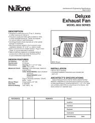
Repair Parts1218193OFF102542830202151213141561617DOWNROD KIT -SOLD SEPARATELY27BLADES - SOLDSEPARATELY7BLADES - SOLDSEPARATELY811262611925325292322313214U.L. Model No.: CF3300
Repair Parts ListingKeyModel NumbersNo. Description CF3300AP00 CF3300ORH001 Hanger Bracket Assembly, 763548 763548Consisting of:* Structural Mounting Plate — —* Hanger Bracket — —2 Hanger Ball Assembly, 763550 763550Consisting of:* Hanger Ball — —3 Downrod Extension (1) 763553 7635534 Ceiling Canopy 763552 763552-15 Upper Trim Ring 763554 763554-16 Upper Decorative Sleeve 763555 763555-17 Decorative Downrod Sleeve Assembly 763563 763563-18 Blade Flange Set Clockwise (4) 763577 763577-19 Blade Flange Set Counter-Clockwise (4) 763579 763579-110 SW22 Wall Control 763859 76385911 Blade Medallion (8) 763575 763575-1* Bag Assembly, Containing: 763587 76358712 3/8 x 2” Lag Bolt (1) — —13 3/8 x 5” Lag Bolt (1) — —14 3/8” Flat washer (2) — —15 Barrel Nut (1) — —16 Bushing (1) — —17 5/32 x 10mm Phillips Screw (1) — —18 Wire Connector (5) — —19 Threaded Stud (2) — —20 Lockwasher (2) — —21 Knurled Knob (2) — —22 Pin, Clevis (1) — —23 Clip, Hairpin (1) — —24 Hex Wrench (1) — —25 Screw, Flat Head, #8-32 x 15mm (17) — —26 Screw, Oval Head, #10-32 x 18mm (25) — —27 Screw, Round Head, 1/4 x 10mm (9) — —28 3/16” Hex Wrench (1) — —29 5/16-18 x 1/4” Cup Point Setscrew (2) — —30 Support Cable Assembly (1) — —31 Motor 763867 76386732 Hub, Rubber 760601 760601— <strong>Owner's</strong> <strong>Manual</strong> BP7385 BP7385Before discarding packaging material, be certain all parts have been removed.HOW TO ORDER REPAIR PARTSWHEN ORDERING REPAIR PARTS, ALWAYS GIVE THE FOLLOWING INFORMATION:• PART NUMBER • NAME OF ITEM• PART DESCRIPTION • MODEL NUMBERThe model number of your Fan will be found on a label attached to the top housing.For repair parts, phone 1-800-654-3545.15U.L. Model No.: CF3300
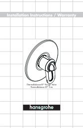
Air Comfort ProductsDIVISION OF EMERSON ELECTRIC CO.8100 W. Florissant • St. Louis, MO 63136Part No. F40BP73850000 Printed in China 02/09 Form No. BP7385U.L. Model No.: CF3300