DEV475 Mastering Object-Oriented Analysis and Design with UML ...
DEV475 Mastering Object-Oriented Analysis and Design with UML ...
DEV475 Mastering Object-Oriented Analysis and Design with UML ...
- No tags were found...

You also want an ePaper? Increase the reach of your titles
YUMPU automatically turns print PDFs into web optimized ePapers that Google loves.
Rational ®Product Training<strong>DEV475</strong> <strong>Mastering</strong><strong>Object</strong>-<strong>Oriented</strong> <strong>Analysis</strong><strong>and</strong> <strong>Design</strong> <strong>with</strong> <strong>UML</strong>Instructor ManualVersion 2003.06.00Volume 1Part# 800-026327-000
Rational University<strong>DEV475</strong> <strong>Mastering</strong> <strong>Object</strong>-<strong>Oriented</strong> <strong>Analysis</strong> <strong>and</strong> <strong>Design</strong> <strong>with</strong> <strong>UML</strong>Instructor ManualVersion 2003.06.00Volume 1February, 2003Copyright © 2002, 2003 Rational Software Corporation. All rights reserved.The contents of this manual <strong>and</strong> the associated software are the property ofRational Software <strong>and</strong>/or its licensors, <strong>and</strong> are protected by United States copyright laws,patent laws, <strong>and</strong> various international treaties. Any reproduction in whole or in partis strictly prohibited. For additional copies of this manual or software, please contactRational Software.Rational, the Rational logo, ClearQuest, ClearCase, Purify, PureCoverage, Rational UnifiedProcess, ClearDDTS, <strong>and</strong> Quantify are trademarks or registered trademarks of RationalSoftware Corporation in the United States <strong>and</strong> in other countries. All names are used foridentification purposes only <strong>and</strong> are trademarks of their respective companies.Microsoft Visual Basic, Windows NT, Windows 2000, <strong>and</strong> Visual SourceSafe are trademarksor registered trademarks of Microsoft Corporation.Java <strong>and</strong> all Java-based marks, among others, are trademarks or registered trademarks of SunMicrosystem’s in the United States <strong>and</strong>/or other countries. All other names are used foridentification purposes only <strong>and</strong> are trademarks of their respective companies.Printed in the United States of America.This manual prepared by:Rational SoftwareRational University18880 Homestead RoadCupertino, CA 95014-0721USATel: 408-863-9900Fax: 408-863-4099Register: 888-RATL-444Web: http://www.rational.com…
ContentsModule 0 About This Course 0-1Course <strong>Object</strong>ives.......................................................................................... 0-3Prerequisites .................................................................................................. 0-6Rational University Curriculum....................................................................... 0-7Module 1 Best Practices of Software Engineering 1-1Practice 1: Develop Iteratively ....................................................................... 1-7Practice 2: Manage Requirements................................................................ 1-11Practice 3: Use Component Architectures .................................................... 1-15Practice 4: Model Visually............................................................................ 1-18Practice 5: Continuously Verify Quality........................................................ 1-22Practice 6: Manage Change ......................................................................... 1-27Module 2 Concepts of <strong>Object</strong> Orientation 2-1What Is <strong>Object</strong> Technology? .......................................................................... 2-4Basic Principles of <strong>Object</strong> Orientation .......................................................... 2-15Representing Classes in the <strong>UML</strong>.................................................................. 2-24Review ........................................................................................................ 2-51Module 3 Requirements Overview 3-1Introduction .................................................................................................. 3-3Key Concepts ................................................................................................ 3-7Use-Case Model .......................................................................................... 3-10Glossary....................................................................................................... 3-19Supplementary Specifications....................................................................... 3-22Review ........................................................................................................ 3-31Module 4 <strong>Analysis</strong> <strong>and</strong> <strong>Design</strong> Overview 4-1Key Concepts ................................................................................................ 4-5<strong>Analysis</strong> <strong>and</strong> <strong>Design</strong> Workflow ..................................................................... 4-11Module 5 Architectural <strong>Analysis</strong> 5-1Architectural <strong>Analysis</strong> Overview ..................................................................... 5-4Key Concepts ................................................................................................ 5-5Define the high-level Organization of Subsystems......................................... 5-10Identify <strong>Analysis</strong> Mechanisms ....................................................................... 5-19Identify Key Abstractions.............................................................................. 5-28Create Use-Case Realizations ....................................................................... 5-32Review ........................................................................................................ 5-38
Module 6 Use-Case <strong>Analysis</strong> 6-1Use-Case <strong>Analysis</strong> Overview .......................................................................... 6-4Supplement The Use-Case Description .......................................................... 6-6Find Classes From Use-Case Behavior ............................................................ 6-8Distribute Use-Case Behavior to Classes ....................................................... 6-26Describe Responsibilities.............................................................................. 6-36Describe Attributes <strong>and</strong> Associations ............................................................ 6-40Use-Case <strong>Analysis</strong> Steps ............................................................................... 6-52Unify <strong>Analysis</strong> Classes .................................................................................. 6-57Review ........................................................................................................ 6-63
AcknowledgmentsThe development of this course was made possible <strong>with</strong> the help of many individuals, but I wouldparticularly like to thank the following for their exceptional participation:Alex Kutsick of Rational University for his course development st<strong>and</strong>ards, instructional designexpertise, attention to detail, <strong>and</strong> correcting my misuse of the English language. Alex ispersonally responsible for ensuring that there is a high-level of consistency throughout thiscourse.Dan Machado of Rational University for his graphics support.Kelli Houston of Rational University for her incredible work on OOADv4.0 <strong>and</strong> OOADv4.2;all I had to do was carry on what she had started.The OOAD Steering Committee: Eric Aker, Sinan Alhir, Alex Barclay, Francesco Bonfiglio,Jerome Desquilbet, Fredrik Ferm, Yves Holvoet, Sean Kelley, Pan Wei Ng, Davyd Norris, JimRuehlin, Jean-Pierre Schoch <strong>and</strong> Mike Tudball.Paul Dreyfus <strong>and</strong> his team of editors for assisting in reviewing the material.Last but certainly not least, DeAnna Roberts of the Rational University production team for herfulfillment <strong>and</strong> logistical support.January, 2003Lee AckermanRational University Sr. Product Manager/ OO Curriculumlackerman@rational.com
Works CitedThe following sources were used to develop this courseware. When quoted directly, we cite the sourceafter the quoted passage. For all other uses, we respectfully acknowledge below the authors’contributions in the development of this courseware.The Deadline: A Novel About Project Management, Tom DeMarco, Dorset House Publishing,1997.Dictionary of <strong>Object</strong> Technology: The Definitive Desk Reference, Donald G. Firesmith <strong>and</strong> EdwardM. Eykholt, Prentice Hall, 1995.Meta Fax, 09/15/97.news@sei, Vol. 1, No. 2.<strong>Object</strong> Technology: A Manager’s Guide, David A. Taylor, Addison-Wesley, 1999.Pattern-<strong>Oriented</strong> Software Architecture: A System of Patterns, Frank Buschman et al., John Wiley &Sons, 1996.The Rational Unified Process, An Introduction, Phillippe Kruchten, Addison-Wesley, 1999.<strong>UML</strong> Distilled, Martin Fowler <strong>and</strong> Kendall Scott, Addison-Wesley, 1997.<strong>UML</strong> Toolkit, Hans-Erik Eriksson <strong>and</strong> Magnus Penker, John Wiley & Sons, 1997.The Unified Modeling Language User Guide, Grady Booch, James Rumbaugh, Ivar Jacobson,Addison-Wesley, 1999.Visual Modeling <strong>with</strong> Rational Rose <strong>and</strong> <strong>UML</strong>, Terry Quatrani, Addison-Wesley, 1998.
<strong>Mastering</strong> OOAD – Instructor NotesInstructor Notes:<strong>Mastering</strong> <strong>Object</strong>-<strong>Oriented</strong> <strong>Analysis</strong><strong>and</strong> <strong>Design</strong> <strong>with</strong> <strong>UML</strong>Module 0: About This CourseModule 0 - About This Course 0 - 1
<strong>Mastering</strong> OOAD – Instructor NotesInstructor Notes:Welcome the students.Encourage feedback <strong>and</strong>questions. The more the studentsget involved, the more successfulthey will be.H<strong>and</strong> out the sign-in sheet <strong>and</strong>registration form.“Before we get started, I wouldlike to discuss the course itself,for a moment, as well as someadministrative details ….”Introductions: instructor <strong>and</strong>students.Get to know everyone. Findout:• Their technicalbackgrounds(for example,software development <strong>and</strong> OOexperience)• What they do in their jobs• What they are expecting fromthe course (for example, whythey are here)• How they plan to use theinformation they receiveOnce you have identified theobjectives, they can be used asguidelines to measure theeffectiveness of the coursethroughout the week. Capturethis on an easel page so you canhang it up <strong>and</strong> keep referencingit.Introduce yourself. H<strong>and</strong> outbusiness cards.Introductions• Your organization• Your role• Your background, experience• <strong>Object</strong> technology experience• Software development experience• Implementation language experience• Your expectations for this course<strong>Mastering</strong> <strong>Object</strong> <strong>Oriented</strong> <strong>Analysis</strong> <strong>and</strong> <strong>Design</strong> <strong>with</strong> <strong>UML</strong>Copyright © 2003 Rational Software, all rights reserved 2Module 0 - About This Course 0 - 2
<strong>Mastering</strong> OOAD – Instructor NotesInstructor Notes:These objectives are asadvertised in the OOAD/<strong>UML</strong>data sheet.Course <strong>Object</strong>ives• Upon completion of the course, participantswill be able to:• Apply an iterative, use case-driven,architecture-centric process to the developmentof a robust design model• Use the Unified Modeling Language (<strong>UML</strong>) torepresent the design model• Apply <strong>Object</strong>-<strong>Oriented</strong> (OO) concepts:abstraction, encapsulation, inheritance,hierarchy, modularity, <strong>and</strong> polymorphism to thedevelopment of a robust design model<strong>Mastering</strong> <strong>Object</strong> <strong>Oriented</strong> <strong>Analysis</strong> <strong>and</strong> <strong>Design</strong> <strong>with</strong> <strong>UML</strong>Copyright © 2003 Rational Software, all rights reserved 3During this course, you will be introduced to the concepts, process, <strong>and</strong>notation for developing a design model. You will be using the RationalUnified Process <strong>Analysis</strong> <strong>and</strong> <strong>Design</strong> workflow as your framework. Theseconcepts can also be applied <strong>with</strong>in any software development process.Module 0 - About This Course 0 - 3
<strong>Mastering</strong> OOAD – Instructor NotesInstructor Notes:Make sure the studentsunderst<strong>and</strong> that this is not anarchitecture course!Course <strong>Object</strong>ives (cont.)• Upon completion of the course, participantswill be able to:• Describe the different views of softwarearchitecture, key mechanisms that are definedin support of that architecture, <strong>and</strong> the effect ofthe architecture on the produced design• Define basic design considerations, includingthe use of patterns<strong>Mastering</strong> <strong>Object</strong> <strong>Oriented</strong> <strong>Analysis</strong> <strong>and</strong> <strong>Design</strong> <strong>with</strong> <strong>UML</strong>Copyright © 2003 Rational Software, all rights reserved 4The concentration will be on those activities that are performed by theobject-oriented designer. Architectural concepts will be introduced <strong>and</strong>discussed, as they drive the design, but this is not an architecture course.Module 0 - About This Course 0 - 4
<strong>Mastering</strong> OOAD – Instructor NotesInstructor Notes:This audience is as advertisedin the OOAD/<strong>UML</strong> data sheet.An ideal student for this courseis an OO programmer wholacks the rigor of applying aformal process.Warn the students that there isa lot of new material, but thatyou will be providing aroadmap. They should stayfocused on the key points <strong>and</strong>not worry about the details.It is imperative that theinstructor review the OOADInstructor Best Practices (IBP)document, since it provides lotsof hints <strong>and</strong> guidelines on whatto emphasize – subjects suchas how to tailor content for anintroductory audience.Intended Audience• Intended Audience• Practitioners who want a basic explanation of<strong>Object</strong>-<strong>Oriented</strong> <strong>Analysis</strong> <strong>and</strong> <strong>Design</strong> (OOAD)concepts, as well as h<strong>and</strong>s-on practicalexperience in applying the techniques• Analysts, designers, software developers<strong>Mastering</strong> <strong>Object</strong> <strong>Oriented</strong> <strong>Analysis</strong> <strong>and</strong> <strong>Design</strong> <strong>with</strong> <strong>UML</strong>Copyright © 2003 Rational Software, all rights reserved 5Module 0 - About This Course 0 - 5
<strong>Mastering</strong> OOAD – Instructor NotesInstructor Notes:Prerequisites• Some experience applying the followingtechniques in a software developmentenvironment• An exposure to object technology including, how to:• Read a use-case model• Add classes, objects, associations <strong>and</strong> how to create simpleinteraction <strong>and</strong> class diagrams• Find classes <strong>and</strong> distribute class behavior• Distinguish between the <strong>UML</strong> <strong>Analysis</strong> class stereotypes:boundary, control, <strong>and</strong> entity• Prerequisites can be achieved through attendance in“Essentials of Visual Modeling <strong>with</strong> <strong>UML</strong>” orequivalent experience<strong>Mastering</strong> <strong>Object</strong> <strong>Oriented</strong> <strong>Analysis</strong> <strong>and</strong> <strong>Design</strong> <strong>with</strong> <strong>UML</strong>Copyright © 2003 Rational Software, all rights reserved 6Module 0 - About This Course 0 - 6
<strong>Mastering</strong> OOAD – Instructor NotesInstructor Notes:This is an information slide. Itgives you the opportunity toadvertise other RU courses.Emphasize the RequirementsManagement <strong>with</strong> Use Cases(RMUC) course, where theylearn about use-cases. Moststudents who are interested inOOAD are also interested inuse cases (in the prior versionof the OOAD course, use caseswere included).Also note that the pathsprovided are alternate pathsthey are not meant to indicateequivalence. The WBT’s areavailable for students that maynot be able to attend ILT’s –but more material is covered inthe ILT’s.Rational University CurriculumCurriculum Flow:<strong>Design</strong>erDEV110Principles ofModeling2 hoursORDEV275Essentialsof VisualModeling<strong>with</strong> <strong>UML</strong>1 dayPath 1DEV111Principles ofUC Modeling<strong>with</strong> <strong>UML</strong>Path 22 hoursDEV112Principles of<strong>Analysis</strong> I2 hours<strong>DEV475</strong><strong>Mastering</strong> <strong>Object</strong><strong>Oriented</strong><strong>Analysis</strong> &<strong>Design</strong> <strong>with</strong> <strong>UML</strong>4 days<strong>Mastering</strong> <strong>Object</strong> <strong>Oriented</strong> <strong>Analysis</strong> <strong>and</strong> <strong>Design</strong> <strong>with</strong> <strong>UML</strong>Copyright © 2003 Rational Software, all rights reserved 7DEV113Principles of<strong>Analysis</strong> II2 hoursInstructor-ledWeb-basedOptionalDEV305Essentials ofRationalRose5 hoursFund. ofRationalRoseThe Rational University curriculum offers the courses shown here <strong>and</strong> onthe next two slides. As you can see, for each major softwaredevelopment team role, Rational University offers a professionaldevelopment course.The Requirements Management <strong>with</strong> Use Cases may be particularlyinteresting to you, as it is where you will learn to develop use cases, theartifacts that drive much of what you do in <strong>Analysis</strong> <strong>and</strong> <strong>Design</strong>.OR1 dayModule 0 - About This Course 0 - 7
<strong>Mastering</strong> OOAD – Instructor NotesInstructor Notes:Rational University CurriculumCurriculum Flow:Enterprise ArchitectPath 1Instructor-ledWeb-basedOptionalPRJ110Principles ofRationalUnifiedProcess3 hoursDEV275Essentialsof VisualModeling<strong>with</strong> <strong>UML</strong>1 dayORDEV111Principles ofUC Modeling<strong>with</strong> <strong>UML</strong>Path 22 hoursDEV112Principles of<strong>Analysis</strong> I2 hoursDEV113Principles of<strong>Analysis</strong> II2 hoursPrinciples ofArchitectingSoftwareSystems3 daysDEV110Principles ofModeling2 hours<strong>DEV475</strong><strong>Mastering</strong> <strong>Object</strong><strong>Oriented</strong><strong>Analysis</strong> &<strong>Design</strong> <strong>with</strong> <strong>UML</strong>4 days<strong>Mastering</strong> <strong>Object</strong> <strong>Oriented</strong> <strong>Analysis</strong> <strong>and</strong> <strong>Design</strong> <strong>with</strong> <strong>UML</strong>Copyright © 2003 Rational Software, all rights reserved 8Module 0 - About This Course 0 - 8
<strong>Mastering</strong> OOAD – Instructor NotesInstructor Notes:Rational University CurriculumCurriculum Flow:AnalystInstructor-ledWeb-basedOptionalREQ310Essentials ofRationalRequisiteProDEV110Principles ofModelingDEV305Essentials ofRationalRose5 hours2 hours2 hoursReq.Management<strong>with</strong> UseCases3 daysORFund. OfRationalRequisiteProORDEV275Essentialsof VisualModeling<strong>with</strong> <strong>UML</strong>ORFund. ofRationalRose1 day1 day1 day<strong>Mastering</strong> <strong>Object</strong> <strong>Oriented</strong> <strong>Analysis</strong> <strong>and</strong> <strong>Design</strong> <strong>with</strong> <strong>UML</strong>Copyright © 2003 Rational Software, all rights reserved 9Module 0 - About This Course 0 - 9
<strong>Mastering</strong> OOAD – Instructor NotesInstructor Notes:This is where you tell thestudents about the materialthey have been provided forthe course. Take the time to letthem find the different books<strong>and</strong> underst<strong>and</strong> what iscontained in them <strong>and</strong> howthey will be used.Describe any additionalmaterials that are not listed onthis slide, but are received inthe Student Packs (smalladditions may have been madeafter this slide was released).Also describe anysupplementary material youmay be providing.Course Materials• Student Manual, Books 1, 2, <strong>and</strong> 3• Additional Information Appendix• Course Registration RequirementsDocument• Payroll Requirements Document• Payroll Architecture H<strong>and</strong>book• Payroll Solution Appendix• Course Registration Models <strong>and</strong> PayrollSolutions Models CD• <strong>UML</strong> User’s Guide by Grady Booch<strong>Mastering</strong> <strong>Object</strong> <strong>Oriented</strong> <strong>Analysis</strong> <strong>and</strong> <strong>Design</strong> <strong>with</strong> <strong>UML</strong>Copyright © 2003 Rational Software, all rights reserved 10The Student Manual contains copies of the slides, as well as detailedStudent Notes. The Student Manual is comprised of two books.The Additional Information Appendix contains a collection ofadditional topics that are not general enough to be included in the basecourse, or may be considered too advanced for the introductoryaudience. These topics may or may not be covered by the instructor.This appendix contains the <strong>UML</strong>-To-Language Maps that show the mapfrom the <strong>UML</strong> to implementation language constructs for the followinglanguages: C++, Java, PowerBuilder, <strong>and</strong> Visual Basic. It also containsinformation on several additional Architectural Mechanisms.The requirements that drive the development of the example <strong>and</strong>exercise design models are documented in the Course RegistrationRequirements Document <strong>and</strong> the Payroll Requirements Document,respectively.The architectural “givens” that guide the students in the development ofthe exercise design model are documented in the Payroll ArchitectureH<strong>and</strong>book.The Payroll Solution Appendix contains the hard-copy of the courseexercise solutions. The Rose models for the course example <strong>and</strong> coursesolutions are provided on the Course Registration Models <strong>and</strong> PayrollSolutions Models CD.Module 0 - About This Course 0 - 10
<strong>Mastering</strong> OOAD – Instructor NotesInstructor Notes:Other Sources of Information• Student Manual• Detailed reference list provided• Rational Unified Process• www.rational.com/products/rup/index.jsp• Rational Web Site• www.rational.com• Rational Developer Network• www.rational.net<strong>Mastering</strong> <strong>Object</strong> <strong>Oriented</strong> <strong>Analysis</strong> <strong>and</strong> <strong>Design</strong> <strong>with</strong> <strong>UML</strong>Copyright © 2003 Rational Software, all rights reserved 11Module 0 - About This Course 0 - 11
<strong>Mastering</strong> OOAD – Instructor NotesInstructor Notes:LogisticsFamiliarize the students <strong>with</strong>the facility, if necessary.• Restrooms•Phones• How people from the outsidecan reach them/leave messages• Where they can connect tothe Internet (where possible)Discuss guidelines such as:what time class starts <strong>and</strong> endseach day; the number ofbreaks; length of breaks; <strong>and</strong>what time to break for lunch.Morning2-Fifteen-minute breaksLunch1 HourAfternoon2-Fifteen-minute breaks<strong>Mastering</strong> <strong>Object</strong> <strong>Oriented</strong> <strong>Analysis</strong> <strong>and</strong> <strong>Design</strong> <strong>with</strong> <strong>UML</strong>Copyright © 2003 Rational Software, all rights reserved 12Module 0 - About This Course 0 - 12
<strong>Mastering</strong> OOAD – Instructor NotesInstructor Notes:<strong>Mastering</strong> <strong>Object</strong>-<strong>Oriented</strong> <strong>Analysis</strong><strong>and</strong> <strong>Design</strong> <strong>with</strong> <strong>UML</strong>Module 1: Best Practices of SoftwareEngineeringModule 1 - Best Practices of Software Engineering 1 - 1
<strong>Mastering</strong> OOAD – Instructor NotesInstructor Notes:The highlighted terms are thekey terms <strong>and</strong> conceptsintroduced in this module.<strong>Object</strong>ives• Identify activities for underst<strong>and</strong>ing <strong>and</strong>solving software engineering problems.• Explain the Six Best Practices.• Present the Rational Unified Process (RUP)<strong>with</strong>in the context of the Six Best Practices.<strong>Mastering</strong> <strong>Object</strong> <strong>Oriented</strong> <strong>Analysis</strong> <strong>and</strong> <strong>Design</strong> <strong>with</strong> <strong>UML</strong>Copyright © 2003 Rational Software, all rights reserved2In this module, you learn about recommended software developmentBest Practices <strong>and</strong> the reasons for these recommendations. Then you seehow the Rational Unified Process (RUP) is designed to help youimplement the Six Best Practices.Module 1 - Best Practices of Software Engineering 1 - 2
<strong>Mastering</strong> OOAD – Instructor NotesInstructor Notes:The highlighted terms are thekey terms <strong>and</strong> conceptsintroduced in this module.Module 1 Content Outline• Software development problems• The Six Best Practices• RUP <strong>with</strong>in the context of the Six BestPractices<strong>Mastering</strong> <strong>Object</strong> <strong>Oriented</strong> <strong>Analysis</strong> <strong>and</strong> <strong>Design</strong> <strong>with</strong> <strong>UML</strong>Copyright © 2003 Rational Software, all rights reserved3Module 1 - Best Practices of Software Engineering 1 - 3
<strong>Mastering</strong> OOAD – Instructor NotesInstructor Notes:Symptoms of Software Development ProblemsUser or business needs not metRequirements not addressedModules not integratingDifficulties <strong>with</strong> maintenanceLate discovery of flawsPoor quality of end-user experiencePoor performance under loadNo coordinated team effortBuild-<strong>and</strong>-release issues<strong>Mastering</strong> <strong>Object</strong> <strong>Oriented</strong> <strong>Analysis</strong> <strong>and</strong> <strong>Design</strong> <strong>with</strong> <strong>UML</strong>Copyright © 2003 Rational Software, all rights reserved4Module 1 - Best Practices of Software Engineering 1 - 4
<strong>Mastering</strong> OOAD – Instructor NotesInstructor Notes:Trace Symptoms to Root CausesAnimation note:The first mouse click highlights:- SymptomThe second mouse clickhighlights:- Root CausesThe third mouse clickhighlights:- Best PracticesSymptoms Root Causes Best PracticesNeeds not metRequirements churnModules don’t not fit fitHard to maintainLate discoveryInsufficient requirementsAmbiguous communicationsBrittle architecturesOverwhelming complexityUndetected inconsistenciesDevelop IterativelyManage RequirementsUse Component ArchitecturesInsufficient automationPoor qualityColliding developersPoor testingWaterfall developmentPoor performanceBuild-<strong>and</strong>-releaseSubjective assessmentUncontrolled changeModel Visually (<strong>UML</strong>)Continuously Verify QualityManage Change<strong>Mastering</strong> <strong>Object</strong> <strong>Oriented</strong> <strong>Analysis</strong> <strong>and</strong> <strong>Design</strong> <strong>with</strong> <strong>UML</strong>Copyright © 2003 Rational Software, all rights reserved5Treat these root causes, <strong>and</strong> you will eliminate the symptoms. Eliminatethe symptoms, <strong>and</strong> you’ll be in a much better position to develop qualitysoftware in a repeatable <strong>and</strong> predictable fashion.Best practices are a set of commercially proven approaches to softwaredevelopment, which, when used in combination, strike at the rootcauses of software development problems. These are called “BestPractices,” not because we can precisely quantify their value, butbecause they are observed to be commonly used in the industry bysuccessful organizations. The Best Practices are harvested from thous<strong>and</strong>sof customers on thous<strong>and</strong>s of projects <strong>and</strong> from industry experts.Module 1 - Best Practices of Software Engineering 1 - 5
<strong>Mastering</strong> OOAD – Instructor NotesInstructor Notes:The highlighted terms are thekey terms <strong>and</strong> conceptsintroduced in this module.Module 1 Content Outline• Software development problems• The Six Best Practices• RUP <strong>with</strong>in the context of the Six BestPractices<strong>Mastering</strong> <strong>Object</strong> <strong>Oriented</strong> <strong>Analysis</strong> <strong>and</strong> <strong>Design</strong> <strong>with</strong> <strong>UML</strong>Copyright © 2003 Rational Software, all rights reserved6Module 1 - Best Practices of Software Engineering 1 - 6
<strong>Mastering</strong> OOAD – Instructor NotesInstructor Notes:You need to keep the concept ofiterative development at a veryhigh level in this module. It iseasy to get bogged down in themany ramifications of iterativedevelopment.Try just to get the conceptacross. The Rational UnifiedProcess Fundamentals coursecovers this in more detail.Practice 1: Develop IterativelyBest PracticesProcess Made PracticalDevelop IterativelyManage RequirementsUse ComponentArchitecturesModel Visually (<strong>UML</strong>)Continuously Verify QualityManage Change<strong>Mastering</strong> <strong>Object</strong> <strong>Oriented</strong> <strong>Analysis</strong> <strong>and</strong> <strong>Design</strong> <strong>with</strong> <strong>UML</strong>Copyright © 2003 Rational Software, all rights reserved7Developing iteratively is a technique that is used to deliver thefunctionality of a system in a successive series of releases of increasingcompleteness. Each release is developed in a specific, fixed time periodcalled an iteration.Each iteration is focused on defining, analyzing, designing, building, <strong>and</strong>testing a set of requirements.Module 1 - Best Practices of Software Engineering 1 - 7
<strong>Mastering</strong> OOAD – Instructor NotesInstructor Notes:Waterfall Development CharacteristicsTo illustrate a problem <strong>with</strong> thewaterfall model: Suppose Iestimate that the project willtake two years, <strong>and</strong> it reallytakes three years. At the end oftwo years, what do I have?Nothing useful works. Nopartial delivery is possible.Diagrams <strong>and</strong> models are great,but they can’t execute.Waterfall ProcessRequirementsanalysis<strong>Design</strong>Code <strong>and</strong> unit testSubsystem integrationSystem test• Delays confirmation ofcritical risk resolution• Measures progress byassessing workproducts that are poorpredictors of time-tocompletion• Delays <strong>and</strong> aggregatesintegration <strong>and</strong> testing• Precludes earlydeployment• Frequently results inmajor unplannediterations<strong>Mastering</strong> <strong>Object</strong> <strong>Oriented</strong> <strong>Analysis</strong> <strong>and</strong> <strong>Design</strong> <strong>with</strong> <strong>UML</strong>Copyright © 2003 Rational Software, all rights reserved8Waterfall development is conceptually straightforward because itproduces a single deliverable. The fundamental problem of thisapproach is that it pushes risk forward in time, when it is costly to undomistakes from earlier phases. An initial design may be flawed <strong>with</strong>respect to its key requirements, <strong>and</strong> late discovery of design defects mayresult in costly overruns <strong>and</strong>/or project cancellation. The waterfallapproach tends to mask the real risks to a project until it is too late to doanything meaningful about them.Module 1 - Best Practices of Software Engineering 1 - 8
<strong>Mastering</strong> OOAD – Instructor NotesInstructor Notes:Iterative Development Produces an ExecutableInitialPlanningPlanningRequirementsManagementEnvironment<strong>Analysis</strong> & <strong>Design</strong>ImplementationTestEvaluationEach iterationresults in anexecutable releaseDeployment<strong>Mastering</strong> <strong>Object</strong> <strong>Oriented</strong> <strong>Analysis</strong> <strong>and</strong> <strong>Design</strong> <strong>with</strong> <strong>UML</strong>Copyright © 2003 Rational Software, all rights reserved9The earliest iterations address the greatest risks. Each iteration includesintegration <strong>and</strong> testing <strong>and</strong> produces an executable release. Iterationshelp:• Resolve major risks before making large investments.• Enable early user feedback.• Make testing <strong>and</strong> integration continuous.• Focus project short-term objective milestones.• Make possible deployment of partial implementations.Iterative processes were developed in response to these waterfallcharacteristics. With an iterative process, the waterfall steps are appliediteratively. Instead of developing the whole system in lock step, anincrement (for example, a subset of system functionality) is selected <strong>and</strong>developed, then another increment, <strong>and</strong> so on. The selection of the firstincrement to be developed is based on risk, <strong>with</strong> the highest priority risksfirst. To address the selected risk(s), choose a subset of use cases.Develop the minimal set of use cases that will allow objectiveverification (that is, through a set of executable tests) of the risks that youhave chosen. Then select the next increment to address the next-highestrisk, <strong>and</strong> so on. Thus you apply the waterfall approach <strong>with</strong>in eachiteration, <strong>and</strong> the system evolves incrementally.Module 1 - Best Practices of Software Engineering 1 - 9
<strong>Mastering</strong> OOAD – Instructor NotesInstructor Notes:Risk ProfilesWaterfall RiskRiskRisk ReductionIterative RiskTime<strong>Mastering</strong> <strong>Object</strong> <strong>Oriented</strong> <strong>Analysis</strong> <strong>and</strong> <strong>Design</strong> <strong>with</strong> <strong>UML</strong>Copyright © 2003 Rational Software, all rights reserved10Iterative development produces the architecture first, allowingintegration to occur as the “verification activity” of the design phase, <strong>and</strong>allowing design flaws to be detected <strong>and</strong> resolved earlier in the lifecycle.Continuous integration throughout the project replaces the “big bang”integration at the end of a project. Iterative development also providesmuch better insight into quality, because system characteristics that arelargely inherent in the architecture (for example, performance, faulttolerance, <strong>and</strong> maintainability) are tangible earlier in the process. Thus,issues are still correctable <strong>with</strong>out jeopardizing target costs <strong>and</strong>schedules.Module 1 - Best Practices of Software Engineering 1 - 10
<strong>Mastering</strong> OOAD – Instructor NotesInstructor Notes:You can generate discussion <strong>with</strong>the students concerning howthey get requirements <strong>and</strong> howthey manage them now.Students who want to know indetail how to managerequirements should take theRequirements Management <strong>with</strong>Use Cases course.Practice 2: Manage RequirementsBest PracticesProcess Made PracticalDevelop IterativelyManage RequirementsUse ComponentArchitecturesModel Visually (<strong>UML</strong>)Continuously Verify QualityManage Change<strong>Mastering</strong> <strong>Object</strong> <strong>Oriented</strong> <strong>Analysis</strong> <strong>and</strong> <strong>Design</strong> <strong>with</strong> <strong>UML</strong>Copyright © 2003 Rational Software, all rights reserved11A report from the St<strong>and</strong>ish Group confirms that a distinct minority ofsoftware development projects is completed on-time <strong>and</strong> on-budget. Intheir report, the success rate was only 16.2%, while challenged projects(operational, but late <strong>and</strong> over-budget) accounted for 52.7%. Impaired(canceled) projects accounted for 31.1%. These failures are attributed toincorrect requirements definition from the start of the project to poorrequirements management throughout the development lifecycle.(Source: Chaos Report, http://www.st<strong>and</strong>ishgroup.com)Module 1 - Best Practices of Software Engineering 1 - 11
<strong>Mastering</strong> OOAD – Instructor NotesInstructor Notes:Requirements ManagementMaking sure you• solve the right problem• build the right systemby taking a systematic approach to• eliciting• organizing• documenting• managingthe changing requirements of asoftware application.<strong>Mastering</strong> <strong>Object</strong> <strong>Oriented</strong> <strong>Analysis</strong> <strong>and</strong> <strong>Design</strong> <strong>with</strong> <strong>UML</strong>Copyright © 2003 Rational Software, all rights reserved12Module 1 - Best Practices of Software Engineering 1 - 12
<strong>Mastering</strong> OOAD – Instructor NotesInstructor Notes:Aspects of Requirements Management• Analyze the Problem• Underst<strong>and</strong> User Needs• Define the System• Manage Scope• Refine the System Definition• Manage Changing Requirements<strong>Mastering</strong> <strong>Object</strong> <strong>Oriented</strong> <strong>Analysis</strong> <strong>and</strong> <strong>Design</strong> <strong>with</strong> <strong>UML</strong>Copyright © 2003 Rational Software, all rights reserved13Module 1 - Best Practices of Software Engineering 1 - 13
<strong>Mastering</strong> OOAD – Instructor NotesInstructor Notes:Map of the TerritoryNeedsProblemProblemSpaceFeaturesSoftwareRequirementsTraceabilitySolutionSpaceTheProductto BeBuiltTest Scripts<strong>Design</strong>UserDocs<strong>Mastering</strong> <strong>Object</strong> <strong>Oriented</strong> <strong>Analysis</strong> <strong>and</strong> <strong>Design</strong> <strong>with</strong> <strong>UML</strong>Copyright © 2003 Rational Software, all rights reserved14Managing requirements involves the translation of stakeholder requestsinto a set of key stakeholder needs <strong>and</strong> system features. These in turn aredetailed into specifications for functional <strong>and</strong> nonfunctionalrequirements. Detailed specifications are translated into test procedures,design, <strong>and</strong> user documentation.Traceability allows us to:• Assess the project impact of a change in a requirement.• Assess the impact of a failure of a test on requirements (that is, if thetest fails, the requirement may not be satisfied).• Manage the scope of the project.• Verify that all requirements of the system are fulfilled by theimplementation.• Verify that the application does only what it is intended to do.• Manage change.Module 1 - Best Practices of Software Engineering 1 - 14
<strong>Mastering</strong> OOAD – Instructor NotesInstructor Notes:Practice 3: Use Component ArchitecturesBest PracticesProcess Made PracticalDevelop IterativelyManage RequirementsUse ComponentArchitecturesModel Visually (<strong>UML</strong>)Continuously Verify QualityManage Change<strong>Mastering</strong> <strong>Object</strong> <strong>Oriented</strong> <strong>Analysis</strong> <strong>and</strong> <strong>Design</strong> <strong>with</strong> <strong>UML</strong>Copyright © 2003 Rational Software, all rights reserved15Software architecture is the development product that gives the highestreturn on investment <strong>with</strong> respect to quality, schedule, <strong>and</strong> cost,according to the authors of Software Architecture in Practice (Len Bass,Paul Clements <strong>and</strong> Rick Kazman [1998] Addison-Wesley). The SoftwareEngineering Institute (SEI) has an effort underway called the ArchitectureTradeoff <strong>Analysis</strong> (ATA) Initiative that focuses on software architecture, adiscipline much misunderstood in the software industry. The SEI hasbeen evaluating software architectures for some time <strong>and</strong> would like tosee architecture evaluation in wider use. As a result of performingarchitecture evaluations, AT&T reported a 10 percent productivityincrease (from news@sei, Vol. 1, No. 2).Module 1 - Best Practices of Software Engineering 1 - 15
<strong>Mastering</strong> OOAD – Instructor NotesInstructor Notes:Resilient Component-Based ArchitecturesYou can encourage discussion atthis point. A single requirement,such as throughput or faulttolerance, affects almost everydesign decision made on asystem. For example, if buildinga transportation system (such asfor trains), it is likely that willhave a “no single point offailure” requirement that mustbe in every developer’s mindevery step of the way. Manyarchitectural mechanisms will bedeveloped to accommodate thatsingle requirement. If you canget some students to describetheir architectural challenges,this point will be moreeffectively driven home.• Resilient• Meets current <strong>and</strong> future requirements• Improves extensibility• Enables reuse• Encapsulates system dependencies• Component-based• Reuse or customize components• Select from commercially available components• Evolve existing software incrementally<strong>Mastering</strong> <strong>Object</strong> <strong>Oriented</strong> <strong>Analysis</strong> <strong>and</strong> <strong>Design</strong> <strong>with</strong> <strong>UML</strong>Copyright © 2003 Rational Software, all rights reserved16Architecture is a part of <strong>Design</strong>. It is about making decisions on how thesystem will be built. But it is not all of the design. It stops at the majorabstractions, or, in other words, the elements that have some pervasive<strong>and</strong> long-lasting effect on system performance <strong>and</strong> ability to evolve.A software system’s architecture is perhaps the most important aspectthat can be used to control the iterative <strong>and</strong> incremental development ofa system throughout its lifecycle.The most important property of an architecture is resilience –flexibility inthe face of change. To achieve it, architects must anticipate evolution inboth the problem domain <strong>and</strong> the implementation technologies toproduce a design that can gracefully accommodate such changes. Keytechniques are abstraction, encapsulation, <strong>and</strong> object-oriented <strong>Analysis</strong><strong>and</strong> <strong>Design</strong>. The result is that applications are fundamentally moremaintainable <strong>and</strong> extensible.Module 1 - Best Practices of Software Engineering 1 - 16
<strong>Mastering</strong> OOAD – Instructor NotesInstructor Notes:Purpose of a Component-Based ArchitectureBecause students vary in theirfamiliarity <strong>with</strong> the concept ofarchitecture applied to software,it is best to get a sense of theirlevel of underst<strong>and</strong>ing beforebeginning this section. If they arefairly unfamiliar, it helps to usethe analogy of buildings or civilengineering. The more complexthe building, the more critical agood architecture is. The longeryou want the building to beuseful, the more effort <strong>and</strong>expense you will put into thearchitecture. And in both ofthese cases, the choice ofarchitect is critical.• Basis for reuse• Component reuse• Architecture reuse• Basis for project management• Planning• Staffing• Delivery• Intellectual control• Manage complexity• Maintain integrity<strong>Mastering</strong> <strong>Object</strong> <strong>Oriented</strong> <strong>Analysis</strong> <strong>and</strong> <strong>Design</strong> <strong>with</strong> <strong>UML</strong>Copyright © 2003 Rational Software, all rights reserved17Component-basedarchitecture <strong>with</strong>layersBusinessspecificApplicationspecificSystemsoftwareMiddlewareDefinition of a (software) component:RUP Definition: A nontrivial, nearly independent, <strong>and</strong> replaceable partof a system that performs a clear function in the context of a welldefinedarchitecture. A component conforms to <strong>and</strong> provides thephysical realization of a set of interfaces.<strong>UML</strong> Definition: A physical, replaceable part of a system that packagesimplementation, <strong>and</strong> that conforms to <strong>and</strong> provides the realization of aset of interfaces. A component represents a physical piece of theimplementation of a system, including software code (source, binary, orexecutable) or equivalents such as scripts or comm<strong>and</strong> files.Module 1 - Best Practices of Software Engineering 1 - 17
<strong>Mastering</strong> OOAD – Instructor NotesInstructor Notes:You may want to lead adiscussion about models <strong>and</strong>why we build them in general.For example, before building abridge, the architect builds amodel <strong>and</strong> has it reviewed.We build models because thething we are studying is socomplex that no one canunderst<strong>and</strong> all of the details. Amodel leaves out the details thatare unimportant. It facilitates ourunderst<strong>and</strong>ing of the largerissues.Practice 4: Model Visually (<strong>UML</strong>)Best PracticesProcess Made PracticalDevelop IterativelyManage RequirementsUse ComponentArchitecturesModel Visually (<strong>UML</strong>)Continuously Verify QualityManage Change<strong>Mastering</strong> <strong>Object</strong> <strong>Oriented</strong> <strong>Analysis</strong> <strong>and</strong> <strong>Design</strong> <strong>with</strong> <strong>UML</strong>Copyright © 2003 Rational Software, all rights reserved18A model is a simplification of reality that provides a complete descriptionof a system from a particular perspective. We build models so that wecan better underst<strong>and</strong> the system we are building. We build models ofcomplex systems because we cannot comprehend any such system in itsentirety.Module 1 - Best Practices of Software Engineering 1 - 18
<strong>Mastering</strong> OOAD – Instructor NotesInstructor Notes:Visual modeling for software isanalogous to blueprints forconstruction.Why Model Visually?• Captures structure <strong>and</strong> behavior• Shows how system elements fit together• Keeps design <strong>and</strong> implementationconsistent• Hides or exposes details as appropriate• Promotes unambiguous communication• The <strong>UML</strong> provides one language for allpractitioners<strong>Mastering</strong> <strong>Object</strong> <strong>Oriented</strong> <strong>Analysis</strong> <strong>and</strong> <strong>Design</strong> <strong>with</strong> <strong>UML</strong>Copyright © 2003 Rational Software, all rights reserved19Modeling is important because it helps the development team visualize,specify, construct, <strong>and</strong> document the structure <strong>and</strong> behavior of systemarchitecture. Using a st<strong>and</strong>ard modeling language such as the <strong>UML</strong> (theUnified Modeling Language), different members of the developmentteam can communicate their decisions unambiguously to one another.Using visual modeling tools facilitates the management of these models,letting you hide or expose details as necessary. Visual modeling alsohelps you maintain consistency among system artifacts - its requirements,designs, <strong>and</strong> implementations. In short, visual modeling helps improve ateam’s ability to manage software complexity.Module 1 - Best Practices of Software Engineering 1 - 19
<strong>Mastering</strong> OOAD – Instructor NotesInstructor Notes:The <strong>UML</strong> provides a graphicallanguage for representingmodels, but provides little or noguidance on when <strong>and</strong> how touse these diagrams. This is anarea in which the RUP helps. Itdescribes the kinds of projectartifacts needed, includingdiagrams, <strong>and</strong> puts them in thecontext of an overall projectplan.Visual Modeling With the Unified Modeling Language• Multiple views• Precise syntax <strong>and</strong>semanticsSequenceDiagramsCollaborationDiagramsUse-CaseDiagramsModelsClassDiagramsStaticDiagrams<strong>Object</strong>DiagramsComponentDiagramsDynamicDiagramsStatechartDiagramsActivityDiagramsDeploymentDiagrams<strong>Mastering</strong> <strong>Object</strong> <strong>Oriented</strong> <strong>Analysis</strong> <strong>and</strong> <strong>Design</strong> <strong>with</strong> <strong>UML</strong>Copyright © 2003 Rational Software, all rights reserved20In building a visual model of a system, many different diagrams areneeded to represent different views of the system. The <strong>UML</strong> provides arich notation for visualizing models. This includes the following keydiagrams:• Use-Case diagrams to illustrate user interactions <strong>with</strong> the system• Class diagrams to illustrate logical structure• <strong>Object</strong> diagrams to illustrate objects <strong>and</strong> links• Component diagrams to illustrate physical structure of the software• Deployment diagrams to show the mapping of software to hardwareconfigurations• Activity diagrams to illustrate flows of events• Statechart diagrams to illustrate behavior• Interaction diagrams (that is, collaboration <strong>and</strong> sequence diagrams)to illustrate behaviorModule 1 - Best Practices of Software Engineering 1 - 20
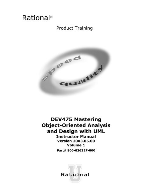
Ư Á¤¹®¼-¿¡ ´ëÇÑ º¸±â¸¦»ç¿ëÀ Ú° ¡ ¿äà »ÇÑ´Ù.È-ÀÏ°ü¸®ÀÚ´Â Àоî¿Â¹®¼-ÀÇ Á¤º¸¸¦ ÇØ´ç ¹®¼-°´Ã¼¿¡ ¼³Á¤À» ¿äûÇÑ´Ù.È-¸é ° ´Ã¼´Â ÀоîµéÀΰ ´Ã¼µé¿¡ ´ëÇØ À̸§º° ·ÎÁ¤·ÄÀ»½ÃÄÑ È-¸é¿¡º¸¿©Á Ø´Ù.1: Doc view re quest ( )user : Clerkuser9: sortByName ( )ma inWnd : Main WndL2: fetchDoc( )4: create ( )8: fillFile ( )fileMgr : FileMgr7: readFile ( )5: readDoc ( )repository : Repository1: Doc view request ( )ma inWnd fileMgr :FileMgr9: sortByName ( )2: fetchDoc( )3: create ( )6: fillDocument( )document :Document4: create ( )8: fillFile ( )3: create ( )6: fillDocument ( )5: readDoc ( )7: readFile ( )gFile : GrpFiledocument : DocumentgFilerepositoryrepRepositoryname : char * = 0readDoc( )readFile( )FileMgrfetchDoc( )sortByName( )(from Persistence)FileListadd( )delete( )read( )FileDocumentListadd( )delete( )fList1Grp Fileread( )open( )create( )fillFile( )Documentname : intdocid : intnumField : intget( )open( )close( )read( )sortFileList( )create( )fillDocument( )read() fill thecode..OpenningReadingadd file [ numberOffile==MAX ] /flag OFFclose fileClosingclose fileadd fileWritingWindow95¹®¼-° ü¸®Å¬óÀ̾ðÆ®.EXEWindowsNTWindowsNT¹®¼-° ü¸® ¿£Áø.EXEWindows95IBMMainframeµ¥ÀÌŸº£À̽º¼-¹öSolarisÀÀ¿ë¼-¹ö.EXEWindows95¹®¼-° ü¸® ¾ÖÇø´AlphaUNIX<strong>Mastering</strong> OOAD – Instructor NotesInstructor Notes:Visual Modeling Using <strong>UML</strong> DiagramsThe point to be made is that the<strong>UML</strong> is the language we use tovisually model. Since it is awidely adopted st<strong>and</strong>ard, itfacilitates the underst<strong>and</strong>ing <strong>and</strong>communication of the visualmodels we create.Activity <strong>and</strong> object diagrams arenot shown on this slide. Thesediagrams can be used to modelworkflows in business processengineering.Actor AUse-CaseDiagramUse Case 1Use Case 2Use Case 3CollaborationDiagramActor BSequenceDiagramClass DiagramGraphicFileStatechartDiagramFileManagerFileRepositoryDocumentDocumentListFileListComponentDiagramDeploymentDiagramForward <strong>and</strong>ReverseEngineeringTargetSystem<strong>Mastering</strong> <strong>Object</strong> <strong>Oriented</strong> <strong>Analysis</strong> <strong>and</strong> <strong>Design</strong> <strong>with</strong> <strong>UML</strong>Copyright © 2003 Rational Software, all rights reserved21Visual modeling <strong>with</strong> the <strong>UML</strong> makes application architecture tangible,permitting us to assess it in multiple dimensions. How portable is it? Canit exploit expected advances in parallel processing? How can you modifyit to support a family of applications?We have discussed the importance of architectural resilience <strong>and</strong> quality.The <strong>UML</strong> enables us to evaluate these key characteristics during earlyiterations — at a point when design defects can be corrected beforethreatening project success.Advances in forward <strong>and</strong> reverse engineering techniques permit changesto an application’s model to be reflected automatically in its sourcecode, <strong>and</strong> changes to its source code to be automatically reflected in itsmodel. This is critical when using an iterative process, in which weexpect such changes <strong>with</strong> each iteration.Module 1 - Best Practices of Software Engineering 1 - 21
<strong>Mastering</strong> OOAD – Instructor NotesInstructor Notes:Do not assume that verifyingquality <strong>and</strong> testing aresynonymous. While testing isused to do the bulk of qualityverification, there are othertechniques that we will mention.Practice 5: Continuously Verify QualityBest PracticesProcess Made PracticalDevelop IterativelyManage RequirementsUse ComponentArchitecturesModel Visually (<strong>UML</strong>)ContinuouslyVerify QualityManage Change<strong>Mastering</strong> <strong>Object</strong> <strong>Oriented</strong> <strong>Analysis</strong> <strong>and</strong> <strong>Design</strong> <strong>with</strong> <strong>UML</strong>Copyright © 2003 Rational Software, all rights reserved22Quality, as used <strong>with</strong>in RUP, is defined as "The characteristic of havingdemonstrated the achievement of producing a product which meets orexceeds agreed-upon requirements, as measured by agreed-uponmeasures <strong>and</strong> criteria, <strong>and</strong> is produced by an agreed-upon process."Given this definition, achieving quality is not simply "meetingrequirements" or producing a product that meets user needs <strong>and</strong>expectations. Quality also includes identifying the measures <strong>and</strong> criteria(to demonstrate the achievement of quality), <strong>and</strong> the implementation ofa process to ensure that the resulting product has achieved the desireddegree of quality (<strong>and</strong> can be repeated <strong>and</strong> managed).In many organizations, software testing accounts for 30% to 50% ofsoftware development costs. Yet most people believe that software is notwell-tested before it is delivered. This contradiction is rooted in two clearfacts. First, testing software is enormously difficult. The different ways aparticular program can behave are almost infinite. Second, testing istypically done <strong>with</strong>out a clear methodology <strong>and</strong> <strong>with</strong>out the requiredautomation or tool support. While the complexity of software makescomplete testing an impossible goal, a well-conceived methodology <strong>and</strong>use of state-of-the-art tools can greatly improve the productivity <strong>and</strong>effectiveness of the software testing.Module 1 - Best Practices of Software Engineering 1 - 22
<strong>Mastering</strong> OOAD – Instructor NotesInstructor Notes:Continuously Verify Your Software’s QualityMany people remember BarryBoehm’s groundbreaking workin Software Economics, where hequantified the relative expenseto fix a bug at different times inthe development lifecycle. Becautious, however, since hiswork was based on the waterfallmodel, not an iterativedevelopment model.The iterative modelfundamentally changes how <strong>and</strong>when we test.CostSoftware problems are100 to 1000 times more costlyto find <strong>and</strong> repair after deployment• Cost to Repair Software• Cost of Lost Opportunities• Cost of Lost CustomersInceptionElaborationConstructionTransition<strong>Mastering</strong> <strong>Object</strong> <strong>Oriented</strong> <strong>Analysis</strong> <strong>and</strong> <strong>Design</strong> <strong>with</strong> <strong>UML</strong>Copyright © 2003 Rational Software, all rights reserved23This principle is driven by a fundamental <strong>and</strong> well-known property ofsoftware development: It is a lot less expensive to correct defects duringdevelopment than to correct them after deployment.• Tests for key scenarios ensure that all requirements are properlyimplemented.• Poor application performance hurts as much as poor reliability.• Verify software reliability — memory leaks, bottlenecks.• Test every iteration — automate test.Module 1 - Best Practices of Software Engineering 1 - 23
<strong>Mastering</strong> OOAD – Instructor NotesInstructor Notes:This is the FURPS model ofdimensions of quality presentedin the RUP. See the RUP fordetails about all these types oftests. Be prepared to define <strong>and</strong>discuss all of them.Testing Dimensions of QualityFunctionality• Test the accurateworkings of eachusage scenario.Usability• Test applicationfrom the perspectiveof convenience toend user.Reliability• Test that the applicationbehaves consistently<strong>and</strong> predictably.Supportability• Test the ability tomaintain <strong>and</strong> supportapplication underproduction use.Performance• Test the online responseunder average <strong>and</strong>peak loading.<strong>Mastering</strong> <strong>Object</strong> <strong>Oriented</strong> <strong>Analysis</strong> <strong>and</strong> <strong>Design</strong> <strong>with</strong> <strong>UML</strong>Copyright © 2003 Rational Software, all rights reserved24Functional testing verifies that a system executes the required use-casescenarios as intended. Functional tests may include the testing offeatures, usage scenarios, <strong>and</strong> security.Usability testing evaluates the application from the user’s perspective.Usability tests focus on human factors, aesthetics, consistency in the userinterface, online <strong>and</strong> context-sensitive Help, wizards <strong>and</strong> agents, userdocumentation, <strong>and</strong> training materials.Reliability testing verifies that the application performs reliably <strong>and</strong> isnot prone to failures during execution (crashes, hangs, <strong>and</strong> memoryleaks). Effective reliability testing requires specialized tools. Reliabilitytests include tests of integrity, structure, stress, contention, <strong>and</strong> volume.Performance testing checks that the target system works functionally<strong>and</strong> reliably under production load. Performance tests includebenchmark tests, load tests, <strong>and</strong> performance profile tests.Supportability testing verifies that the application can be deployed asintended. Supportability tests include installation <strong>and</strong> configuration tests.Module 1 - Best Practices of Software Engineering 1 - 24
<strong>Mastering</strong> OOAD – Instructor NotesInstructor Notes:Test Each IterationThe point to be made on thisslide is that it is important to startautomating tests in the earliestiterations. Some people thinkthat you do not need toautomate testing until the lateriterations, when requirementsare pretty stable. Even if youexpect that the requirements,<strong>and</strong> hence the tests, are stillunstable, it is still more efficientto automate.<strong>UML</strong> Model<strong>and</strong>ImplementationTestsIteration 1Test Suite 1Iteration 2Test Suite 2Iteration 3Test Suite 3Iteration 4Test Suite 4The icons in the test suites aretest icons from the RUP.<strong>Mastering</strong> <strong>Object</strong> <strong>Oriented</strong> <strong>Analysis</strong> <strong>and</strong> <strong>Design</strong> <strong>with</strong> <strong>UML</strong>Copyright © 2003 Rational Software, all rights reserved25In each iteration, automated tests are created that test the requirementsaddressed in that iteration. As new requirements are added insubsequent iterations, new tests are generated <strong>and</strong> run. At times, arequirement may be changed in a later iteration. In that case, the testsassociated <strong>with</strong> the changed requirement may be modified or simplyregenerated by an automated tool.Module 1 - Best Practices of Software Engineering 1 - 25
<strong>Mastering</strong> OOAD – Instructor NotesInstructor Notes:Test Within the Product Development LifecycleKey Points:• Point out where testing fits inthe product developmentlifecycle.IterationXRequirements CaptureIterationX + 1<strong>Analysis</strong> <strong>and</strong> <strong>Design</strong>IterationX + 2• Stress the advantages ofstarting to test early in thedevelopment lifecycle.ProjectPlanningDefineMissionBuildValidateBuildImplementationTest <strong>and</strong>EvaluateAchieveMissionImproveAssetsVerify ApproachTime<strong>Mastering</strong> <strong>Object</strong> <strong>Oriented</strong> <strong>Analysis</strong> <strong>and</strong> <strong>Design</strong> <strong>with</strong> <strong>UML</strong>Copyright © 2003 Rational Software, all rights reserved26The testing lifecycle is a part of the software lifecycle; both should start inan equivalent time frame. The design <strong>and</strong> development process for testscan be as complex <strong>and</strong> arduous as the process for developing thesoftware product itself. If tests do not start in line <strong>with</strong> the first executablesoftware releases, the test effort will back load the discovery ofpotentially important problems until late in the development cycle.Module 1 - Best Practices of Software Engineering 1 - 26
<strong>Mastering</strong> OOAD – Instructor NotesInstructor Notes:Practice 6: Manage ChangeControl of change is especiallyimportant in an iterative project.Artifacts are generally producedincrementally. At the end ofeach iteration, anotherincrement is put underconfiguration control.Otherwise, no progress will bemade, <strong>and</strong> iterations will notconverge toward creating acomplete <strong>and</strong> consistent system.We are not just talking aboutchanges to source code, but alsochanges to requirements,models, documents, plans, <strong>and</strong>all development artifacts.<strong>Mastering</strong> <strong>Object</strong> <strong>Oriented</strong> <strong>Analysis</strong> <strong>and</strong> <strong>Design</strong> <strong>with</strong> <strong>UML</strong>Copyright © 2003 Rational Software, all rights reservedBest PracticesProcess Made PracticalDevelop IterativelyManage RequirementsUse ComponentArchitecturesModel Visually (<strong>UML</strong>)Continuously Verify QualityManage Change27You cannot stop change from being introduced into a project. However,you must control how <strong>and</strong> when changes are introduced into projectartifacts, <strong>and</strong> who introduces those changes.You must also synchronize changes across development teams <strong>and</strong>locations.Unified Change Management (UCM) is the Rational Software approachto managing change in software system development, from requirementsto release.Module 1 - Best Practices of Software Engineering 1 - 27
<strong>Mastering</strong> OOAD – Instructor NotesInstructor Notes:If possible, use examples fromyour experience to illustratewhat can go wrong when doingparallel development <strong>with</strong>outadequate controls — forexample, describe twoprogrammers makingsimultaneous updates to thesame component, or a veryimportant test failing in front of acustomer because the wrongversion of the test case was run.What Do You Want to Control?• Secure workspaces for each developer• Automated integration/build management• Parallel developmentConfigurationManagement ismore than justcheck-in <strong>and</strong>check-outWorkspaceManagementProcessIntegrationREPORTALERTParallelDevelopmentBuildManagement<strong>Mastering</strong> <strong>Object</strong> <strong>Oriented</strong> <strong>Analysis</strong> <strong>and</strong> <strong>Design</strong> <strong>with</strong> <strong>UML</strong>Copyright © 2003 Rational Software, all rights reserved28Establishing a secure workspace for each developer provides isolationfrom changes made in other workspaces <strong>and</strong> control of all softwareartifacts — models, code, documents <strong>and</strong> so forth.A key challenge to developing software-intensive systems is the need tocope <strong>with</strong> multiple developers, organized into different teams, possiblyat different sites, all working together on multiple iterations, releases,products, <strong>and</strong> platforms. In the absence of disciplined control, thedevelopment process rapidly degrades into chaos. Progress can come toa stop.Three common problems that result are:• Simultaneous update: When two or more roles separately modifythe same artifact, the last one to make changes destroys the work ofthe former.• Limited notification: When a problem is fixed in shared artifacts,some of the users are not notified of the change.• Multiple versions: With iterative development, it would not beunusual to have multiple versions of an artifact in different stages ofdevelopment at the same time. For example, one release is incustomer use, one is in test, <strong>and</strong> one is still in development. If aproblem is identified in any one of the versions, the fix must bepropagated among all of them.Module 1 - Best Practices of Software Engineering 1 - 28
<strong>Mastering</strong> OOAD – Instructor NotesInstructor Notes:Aspects of a CM System• Change Request Management (CRM)• Configuration Status Reporting• Configuration Management (CM)• Change Tracking• Version Selection• Software Manufacture<strong>Mastering</strong> <strong>Object</strong> <strong>Oriented</strong> <strong>Analysis</strong> <strong>and</strong> <strong>Design</strong> <strong>with</strong> <strong>UML</strong>Copyright © 2003 Rational Software, all rights reserved29Change Request Management (CRM) addresses the organizationalinfrastructure required to assess the cost <strong>and</strong> schedule impacts of arequested change to the existing product. CRM addresses the workingsof a Change Review Team or Change Control Board.Configuration Status Reporting (Measurement) is used to describe the“state” of the product based on the type, number, rate <strong>and</strong> severity ofdefects found <strong>and</strong> fixed during the course of product development.Metrics derived under this aspect, through either audits or raw data, areuseful in determining the overall completeness of the project.Configuration Management (CM) describes the product structure <strong>and</strong>identifies its constituent configuration items, which are treated as singleversionable entities in the configuration management process. CM deals<strong>with</strong> defining configurations, building <strong>and</strong> labeling, <strong>and</strong> collectingversioned artifacts into constituent sets, as well as <strong>with</strong> maintainingtraceability among these versions.Change Tracking describes what is done to components for what reason<strong>and</strong> at what time. It serves as the history of <strong>and</strong> rationale for changes. It isquite separate from assessing the impact of proposed changes asdescribed under Change Request Management.Version Selection ensures that the right versions of configuration itemsare selected for change or implementation. Version selection relies on asolid foundation of “configuration identification.”Software Manufacture covers the need to automate the steps tocompile, test, <strong>and</strong> package software for distribution.Module 1 - Best Practices of Software Engineering 1 - 29
<strong>Mastering</strong> OOAD – Instructor NotesInstructor Notes:On support for UCM in theRUP:The CM concepts described inUCM are covered in the RUP bythe following workflow details:• Create Project CMEnvironments•Change <strong>and</strong> DeliverConfiguration Items• Manage Baselines <strong>and</strong>ReleasesUCM does not cover the RUPactivities described in theworkflows:• Monitor <strong>and</strong> ReportConfiguration Status• Manage Change Requests.The activities described in theRUP workflow detail —Plan Project Configuration <strong>and</strong>Change Control — are at ahigher level of abstraction thanthe notion of a project describedin UCM. However, UCM doescover the fact that policies needto be set, <strong>and</strong> that there is a CMprocess to be followed to ensurethat all project artifacts aremaintained under configurationcontrol.Unified Change Management (UCM)UCM involves:• Management across the lifecycle• System• Project Management• Activity-Based Management• Tasks• Defects• Enhancements• Progress Tracking• Charts• Reports<strong>Mastering</strong> <strong>Object</strong> <strong>Oriented</strong> <strong>Analysis</strong> <strong>and</strong> <strong>Design</strong> <strong>with</strong> <strong>UML</strong>Copyright © 2003 Rational Software, all rights reserved30Unified Change Management (UCM) is Rational Software's approach tomanaging change in software system development, from requirements torelease. UCM spans the development lifecycle, defining how to managechange to requirements, design models, documentation, components,test cases, <strong>and</strong> source code.One of the key aspects of the UCM model is that it unifies the activitiesused to plan <strong>and</strong> track project progress <strong>and</strong> the artifacts undergoingchange.Module 1 - Best Practices of Software Engineering 1 - 30
<strong>Mastering</strong> OOAD – Instructor NotesInstructor Notes:Best Practices Reinforce Each OtherThis slide may be confusingunless it is explained properly.You have already discussed eachBest Practice individually in thismodule. This slide is intended toillustrate how the Best Practicesused together provide muchmore benefit than eachindividually. The slide onlyillustrates how one of the BestPractices (Develop Iteratively)supports the others. How othersinteract might make a gooddiscussion point for the students.For example, how do ManageChange <strong>and</strong> Continuously VerifyQuality relate? The answer isthat there is no point in runninga test against an unknownconfiguration <strong>and</strong> no point inwriting a defect against anunknown baseline. Similarly,there is no point in controllingchanges until you have reacheda stable level of quality in aproduct.Best PracticesDevelop IterativelyManage RequirementsUse Component ArchitecturesModel Visually (<strong>UML</strong>)Continuously Verify QualityManage Change<strong>Mastering</strong> <strong>Object</strong> <strong>Oriented</strong> <strong>Analysis</strong> <strong>and</strong> <strong>Design</strong> <strong>with</strong> <strong>UML</strong>Copyright © 2003 Rational Software, all rights reserved31Ensures users are involvedas requirements evolveValidates architecturaldecisions early onAddresses complexity ofdesign/implementation incrementallyMeasures quality early <strong>and</strong> oftenEvolves baselines incrementallyIn the case of our Six Best Practices, the whole is much greater than thesum of the parts. Each of the Best Practices reinforces <strong>and</strong>, in somecases, enables the others. This slide shows just one example: howiterative development leverages the other five Best Practices. However,each of the other five practices also enhances iterative development. Forexample, iterative development done <strong>with</strong>out adequate requirementsmanagement can easily fail to converge on a solution. Requirements canchange at will, users cannot agree, <strong>and</strong> the iterations go on forever.When requirements are managed, this is less likely to happen. Changesto requirements are visible, <strong>and</strong> the impact on the development processis assessed before the changes are accepted. Convergence on a stable setof requirements is ensured. Similarly, each pair of Best Practices providesmutual support. Hence, although it is possible to use one Best Practice<strong>with</strong>out the others, it is not recommended, since the resulting benefitswill be significantly decreased.Module 1 - Best Practices of Software Engineering 1 - 31
<strong>Mastering</strong> OOAD – Instructor NotesInstructor Notes:The highlighted terms are thekey terms <strong>and</strong> conceptsintroduced in this module.Module 1 Content Outline• Software development problems• The Six Best Practices• RUP <strong>with</strong>in the context of the Six BestPractices<strong>Mastering</strong> <strong>Object</strong> <strong>Oriented</strong> <strong>Analysis</strong> <strong>and</strong> <strong>Design</strong> <strong>with</strong> <strong>UML</strong>Copyright © 2003 Rational Software, all rights reserved32Module 1 - Best Practices of Software Engineering 1 - 32
<strong>Mastering</strong> OOAD – Instructor NotesInstructor Notes:Rational Unified Process Implements Best PracticesBest PracticesProcess Made PracticalDevelop IterativelyManage RequirementsUse Component ArchitecturesModel Visually (<strong>UML</strong>)Continuously Verify QualityManage Change<strong>Mastering</strong> <strong>Object</strong> <strong>Oriented</strong> <strong>Analysis</strong> <strong>and</strong> <strong>Design</strong> <strong>with</strong> <strong>UML</strong>Copyright © 2003 Rational Software, all rights reserved33Why have a process?• Provides guidelines for efficient development of quality software• Reduces risk <strong>and</strong> increases predictability• Promotes a common vision <strong>and</strong> culture• Captures <strong>and</strong> institutionalizes Best PracticesThe Rational Unified Process (RUP) is a generic business process forobject-oriented software engineering. It describes a family of relatedsoftware-engineering processes sharing a common structure <strong>and</strong> acommon process architecture. It provides a disciplined approach toassigning tasks <strong>and</strong> responsibilities <strong>with</strong>in a development organization. Itsgoal is to ensure the production of high-quality software that meets theneeds of its end users <strong>with</strong>in a predictable schedule <strong>and</strong> budget. TheRUP captures the Best Practices in modern software development in aform that can be adapted for a wide range of projects <strong>and</strong> organizations.The <strong>UML</strong> provides a st<strong>and</strong>ard for the artifacts of development (semanticmodels, syntactic notation, <strong>and</strong> diagrams): the things that must becontrolled <strong>and</strong> exchanged. But the <strong>UML</strong> is not a st<strong>and</strong>ard for thedevelopment process. Despite all of the value that a common modelinglanguage brings, you cannot achieve successful development of today’scomplex systems solely by the use of the <strong>UML</strong>. Successful developmentalso requires employing an equally robust development process, which iswhere the RUP comes in.Module 1 - Best Practices of Software Engineering 1 - 33
<strong>Mastering</strong> OOAD – Instructor NotesInstructor Notes:Achieving Best Practices• Iterative approach• Guidance for activities<strong>and</strong> artifacts• Process focus onarchitecture• Use cases that drivedesign <strong>and</strong>implementation• Models that abstractthe system<strong>Mastering</strong> <strong>Object</strong> <strong>Oriented</strong> <strong>Analysis</strong> <strong>and</strong> <strong>Design</strong> <strong>with</strong> <strong>UML</strong>Copyright © 2003 Rational Software, all rights reserved34Examples:• The dynamic structure (phases <strong>and</strong> iterations) of the Rational UnifiedProcess creates the basis of iterative development.• The Project Management discipline describes how to set up <strong>and</strong>execute a project using phases <strong>and</strong> iterations.• The Use-Case Model of the Requirements discipline <strong>and</strong> the risk listdetermine what functionality you implement in an iteration.• The Workflow Details of the Requirements discipline show theactivities <strong>and</strong> artifacts that make requirements management possible.• The iterative approach allows you to progressively identifycomponents, <strong>and</strong> to decide which one to develop, which one toreuse, <strong>and</strong> which one to buy.• The Unified Modeling Language (<strong>UML</strong>) used in the process representsthe basis of visual modeling <strong>and</strong> has become the de facto modelinglanguage st<strong>and</strong>ard.• The focus on software architecture allows you to articulate thestructure: the components, the ways in which they integrate, <strong>and</strong> thefundamental mechanisms <strong>and</strong> patterns by which they interact.Module 1 - Best Practices of Software Engineering 1 - 34
<strong>Mastering</strong> OOAD – Instructor NotesInstructor Notes:A Team-Based Definition of ProcessIt can be very difficult to explainwhat a process is, if the studentsare not already familiar <strong>with</strong> it.An informal example mostpeople can relate to is theprocess of balancing acheckbook at the end of themonth. Most of us havedeveloped a process we use thatincludes the same steps everymonth. It shortens the timerequired to accomplish the task<strong>and</strong> ensures that we do notforget any steps. The sameapplies to a software-engineeringprocess. We want it to berepeatable <strong>and</strong> to ensure that allrequired tasks are accomplishedwhen required. Of course, asoftware-engineering process ismuch more complex thanbalancing a checkbook, <strong>and</strong>there is a tremendous amount ofinformation contained in theRUP.A process defines Who is doing What,When, <strong>and</strong> How, in order to reach a certaingoal.New or changedrequirements<strong>Mastering</strong> <strong>Object</strong> <strong>Oriented</strong> <strong>Analysis</strong> <strong>and</strong> <strong>Design</strong> <strong>with</strong> <strong>UML</strong>Copyright © 2003 Rational Software, all rights reservedSoftware EngineeringProcess35New or changedsystemModule 1 - Best Practices of Software Engineering 1 - 35
<strong>Mastering</strong> OOAD – Instructor NotesInstructor Notes:Process Structure - Lifecycle PhasesThe Student Notes are quiteextensive. There is no need to gointo that much detail in class.The important thing is tounderst<strong>and</strong> how the RUP usesphases to organize the lifecycle.You can also mention that wedeliberately chose names that donot match the waterfall names(analysis, design,implementation, <strong>and</strong> test) toemphasize that they are not thesame as the waterfall phases.Some ways of describing thephases in common terminology:Inception — Bid <strong>and</strong> proposalElaboration — BuildingblueprintsConstruction — I think I’mdone.Transition — How do usersreact?timeInception Elaboration Construction TransitionRational Unified Process has four phases:• Inception - Define the scope of project• Elaboration - Plan project, specify features <strong>and</strong>baseline architecture• Construction - Build the product• Transition - Transition the product into end-usercommunity<strong>Mastering</strong> <strong>Object</strong> <strong>Oriented</strong> <strong>Analysis</strong> <strong>and</strong> <strong>Design</strong> <strong>with</strong> <strong>UML</strong>Copyright © 2003 Rational Software, all rights reservedDuring Inception, we define the scope of the project: what is included<strong>and</strong> what is not. We do this by identifying all the actors <strong>and</strong> use cases,<strong>and</strong> by drafting the most essential use cases (typically 20% of thecomplete model). A business plan is developed to determine whetherresources should be committed to the project.During Elaboration, we focus on two things: getting a good grasp of therequirements (80% complete) <strong>and</strong> establishing an architectural baseline.If we have a good grasp of the requirements <strong>and</strong> the architecture, wecan eliminate a lot of the risks, <strong>and</strong> we will have a good idea of howmuch work remains to be done. We can make detailed cost/resourceestimations at the end of Elaboration.During Construction, we build the product in several iterations up to abeta release.During Transition, we move the product to the end user <strong>and</strong> focus onend-user training, installation, <strong>and</strong> support.The amount of time spent in each phase varies. For a complex project<strong>with</strong> many technical unknowns <strong>and</strong> unclear requirements, Elaborationmay include three-to-five iterations. For a simple project, whererequirements are known <strong>and</strong> the architecture is simple, Elaboration mayinclude only a single iteration.36Module 1 - Best Practices of Software Engineering 1 - 36
<strong>Mastering</strong> OOAD – Instructor NotesInstructor Notes:Phase Boundaries Mark Major MilestonesThe Student Notes are extensive,<strong>and</strong> there is no need to go intodetail regarding each milestone.The most important point to getacross is that there are formalmilestones marking majordecision points <strong>with</strong> the RUPlifecycle, just as there are in thewaterfall approach.The criteria listed in the StudentNotes are extensive because theyare thorough. However, onlyone or two of the criteria at eachpoint are really important.timeInception Elaboration Construction TransitionLifecycle<strong>Object</strong>iveMilestone(LCO)LifecycleArchitectureMilestone(LCA)Initial OperationalCapabilityMilestone(IOC)ProductRelease<strong>Mastering</strong> <strong>Object</strong> <strong>Oriented</strong> <strong>Analysis</strong> <strong>and</strong> <strong>Design</strong> <strong>with</strong> <strong>UML</strong>Copyright © 2003 Rational Software, all rights reserved37At each of the major milestones, we review the project <strong>and</strong> decidewhether to proceed <strong>with</strong> it as planned, to cancel the it, or to revise it.The criteria used to make these decisions vary by phase.LCO: scope is agreed upon <strong>and</strong> risks are understood <strong>and</strong> reasonableLCA: high risks are addressed <strong>and</strong> architecture is stableIOC: product is complete <strong>and</strong> quality is acceptableThe evaluation criteria for the Inception phase (LCO) include:stakeholder concurrence on scope definition <strong>and</strong> cost/scheduleestimates; requirements underst<strong>and</strong>ing as evidenced by the fidelity ofthe primary use cases; credibility of cost/schedule estimates, priorities,risks, <strong>and</strong> development process; depth <strong>and</strong> breadth of any architecturalprototype; actual expenditures versus planned expenditures.The evaluation criteria for the Elaboration phase (LCA) include: stabilityof the product vision <strong>and</strong> architecture; resolution of major risk elements;adequate planning <strong>and</strong> reasonable estimates for project completion;stakeholder acceptance of the product vision <strong>and</strong> project plan; <strong>and</strong>acceptable expenditure level.The evaluation criteria for the Construction phase (IOC) include:stability <strong>and</strong> maturity of the product release (that is, is it ready to bedeployed?); readiness of the stakeholders for the transition; <strong>and</strong>acceptable expenditure level.At the end of the Transition phase, we decide whether to release theproduct. We base this primarily on the level of user satisfaction achievedduring the Transition phase. Often this milestone coincides <strong>with</strong> theinitiation of another development cycle to improve or enhance theproduct. In many cases, this new development cycle may already beunderway.Module 1 - Best Practices of Software Engineering 1 - 37
<strong>Mastering</strong> OOAD – Instructor NotesInstructor Notes:Iterations <strong>and</strong> PhasesInception Elaboration Construction TransitionPreliminaryIterationArchitect.IterationArchitect.IterationDevel.IterationDevel.IterationDevel.IterationTransition TransitionIteration IterationMinor Milestones: ReleasesAn iteration is a distinct sequence of activities based onan established plan <strong>and</strong> evaluation criteria, resulting in anexecutable release (internal or external).<strong>Mastering</strong> <strong>Object</strong> <strong>Oriented</strong> <strong>Analysis</strong> <strong>and</strong> <strong>Design</strong> <strong>with</strong> <strong>UML</strong>Copyright © 2003 Rational Software, all rights reserved38Within each phase, there is a series of iterations. The number ofiterations per phase will vary. Each iteration results in an executablerelease encompassing larger <strong>and</strong> larger subsets of the final application.An internal release is kept <strong>with</strong>in the development environment <strong>and</strong>(optionally) demonstrated to the stakeholder community. We providestakeholders (usually users) <strong>with</strong> an external release for installation intheir environment. External releases are much more expensive becausethey require user documentation <strong>and</strong> technical support — because ofthis, they normally occur only during the Transition phase.The end of an iteration marks a minor milestone. At this point, we assesstechnical results <strong>and</strong> revise future plans as necessary.Module 1 - Best Practices of Software Engineering 1 - 38
<strong>Mastering</strong> OOAD – Instructor NotesInstructor Notes:Bringing It All Together: The Iterative ApproachCan iterations overlap?No. Our model is to show nooverlap among iterations. In alarge project, several teams maywork in parallel on their portionsof the iteration, but we do notconsider these to be separateiterations.How many iterations should youhave?It depends on many factors. Erron the side of too manyiterations.Animation note: The callouts<strong>and</strong> black rectangle appear twoseconds after the slide.Disciplinesgroupactivitieslogically.<strong>Mastering</strong> <strong>Object</strong> <strong>Oriented</strong> <strong>Analysis</strong> <strong>and</strong> <strong>Design</strong> <strong>with</strong> <strong>UML</strong>Copyright © 2003 Rational Software, all rights reserved39In aniteration,you walkthrough alldisciplines.This slide illustrates how phases <strong>and</strong> iterations (the time dimension)relate to the development activities (the discipline dimension). Therelative size of each color area in the graph indicates how much of theactivity is performed in each phase or iteratino.Each iteration involves activities from all disciplines. The relative amountof work related to the disciplines changes between iterations. Forinstance, during late Construction, the main work is related toImplementation <strong>and</strong> Test <strong>and</strong> very little work on Requirements is done.Note that requirements are not necessarily complete by the end ofElaboration. It is acceptable to delay the analysis <strong>and</strong> design of wellunderstoodportions of the system until Construction because they arelow in risk.Module 1 - Best Practices of Software Engineering 1 - 39
<strong>Mastering</strong> OOAD – Instructor NotesInstructor Notes:Disciplines Produce ModelsYou can relate this back toprevious slides that describe thesystem model <strong>and</strong> the manydiagrams needed to fullycommunicate its content. Onecan consider all of the modelslisted here, taken together, to be“the system model.”The only model that is a littledifferent is the Business Model. Itdescribes the business at large,not just the automated part. Theother models describe theinformation system that supportsthe Business Model.It is a good idea to point out thateach of these models isincrementally developed acrossmany iterations.DisciplinesModelsRealizedBy<strong>Mastering</strong> <strong>Object</strong> <strong>Oriented</strong> <strong>Analysis</strong> <strong>and</strong> <strong>Design</strong> <strong>with</strong> <strong>UML</strong>Copyright © 2003 Rational Software, all rights reservedBusinessModelingBusiness Use-Case ModelBB B BBusiness<strong>Object</strong> ModelImplementationRequirementsUse-CaseModelAutomatedBy40<strong>Analysis</strong> &<strong>Design</strong>Realized By<strong>Design</strong> ModelImplementedByImplementationModelThe RUP takes a model-driven approach. Several models are needed tofully describe the evolving system. Each major discipline produces one ofthose models. The models are developed incrementally across iterations.•The Business Model is a model of what the business processes are<strong>and</strong> of the business environment. It can be used to generaterequirements of supporting information systems.•The Use-Case Model is a model of what the system is supposed todo <strong>and</strong> of the system environment.•The <strong>Design</strong> Model is an object model describing the realization ofuse cases. It serves as an abstraction of the implementation model<strong>and</strong> its source code.•The Implementation Model is a collection of components <strong>and</strong> theimplementation subsystems that contain them.Test Suites are derived from many of these models.Module 1 - Best Practices of Software Engineering 1 - 40
<strong>Mastering</strong> OOAD – Instructor NotesInstructor Notes:An activity diagram showsmultiple possible sequences ofworkflow details. Generally aworkflow detail is the lowestlevel represented when a plan iscreated.Make clear that the workflowwill vary, depending on thephase, iteration location <strong>with</strong>in aphase, <strong>and</strong> the technology beingused. The Project Management<strong>and</strong> <strong>Analysis</strong> <strong>and</strong> <strong>Design</strong>disciplines are good examples ofthis.Disciplines Guide Iterative Development<strong>Mastering</strong> <strong>Object</strong> <strong>Oriented</strong> <strong>Analysis</strong> <strong>and</strong> <strong>Design</strong> <strong>with</strong> <strong>UML</strong>Copyright © 2003 Rational Software, all rights reservedBusinessModeling:Workflow41Requirements:WorkflowWithin a discipline, workflows group activities that are done together.Discipline workflows will be present in varying degrees, depending onthe phase.Module 1 - Best Practices of Software Engineering 1 - 41
<strong>Mastering</strong> OOAD – Instructor NotesInstructor Notes:Overview of Rational Unified Process ConceptsDivided into Considers Described byPhase Iteration DisciplineParticipates inWorkflowDetailReferencesRoleResponsible forActivityModifiesDocumentModelArtifactModelElement<strong>Mastering</strong> <strong>Object</strong> <strong>Oriented</strong> <strong>Analysis</strong> <strong>and</strong> <strong>Design</strong> <strong>with</strong> <strong>UML</strong>Copyright © 2003 Rational Software, all rights reserved42Basic Concepts in the RUPA software lifecycle in the RUP is decomposed over time into foursequential phases, each concluded by a major milestone. Each phase isessentially a span of time between two major milestones.An iteration is a pass through a sequence of process disciplines. Eachiteration concludes <strong>with</strong> the release of an executable product.A discipline shows all the activities that you may go through to producea particular set of artifacts. We describe these disciplines at an overviewlevel — a summary of all roles, activities, <strong>and</strong> artifacts that are involved.A workflow detail is a grouping of activities that are done "together,"presented <strong>with</strong> input <strong>and</strong> resulting artifacts.A role defines the behavior <strong>and</strong> responsibilities of an individual, or a setof individuals working together as a team.An activity is the smallest piece of work that is relevant.Artifacts: These are the modeling constructs <strong>and</strong> documents thatactivities evolve, maintain, or use as input.• Documents: These record system requirements, including usability,reliability, performance, <strong>and</strong> supportability requirements.• Model: This is a simplified view of a system. It shows the essentialsof the system from a particular perspective <strong>and</strong> hides the nonessentialdetails.• Model elements: These help the team visualize, construct, <strong>and</strong>document the structure <strong>and</strong> behavior of the system, <strong>with</strong>out gettinglost in complexity.Module 1 - Best Practices of Software Engineering 1 - 42
<strong>Mastering</strong> OOAD – Instructor NotesInstructor Notes:Review• Best Practices guide software engineeringby addressing root causes.• Best Practices reinforce each other.• Process guides a team on who does what,when, <strong>and</strong> how.• The Rational Unified Process is a means ofachieving Best Practices.<strong>Mastering</strong> <strong>Object</strong> <strong>Oriented</strong> <strong>Analysis</strong> <strong>and</strong> <strong>Design</strong> <strong>with</strong> <strong>UML</strong>Copyright © 2003 Rational Software, all rights reserved43Module 1 - Best Practices of Software Engineering 1 - 43
<strong>Mastering</strong> OOAD – Instructor NotesInstructor Notes:<strong>Mastering</strong> <strong>Object</strong> <strong>Oriented</strong> <strong>Analysis</strong> <strong>and</strong> <strong>Design</strong> <strong>with</strong> <strong>UML</strong>Copyright © 2003 Rational Software, all rights reserved44Module 1 - Best Practices of Software Engineering 1 - 44
<strong>Mastering</strong> OOAD – Instructor NotesInstructor Notes:<strong>Mastering</strong> <strong>Object</strong>-<strong>Oriented</strong> <strong>Analysis</strong><strong>and</strong> <strong>Design</strong> <strong>with</strong> <strong>UML</strong>Module 2: Concepts of <strong>Object</strong> OrientationModule 2 - Concepts of <strong>Object</strong> Orientation 2 - 1
<strong>Mastering</strong> OOAD – Instructor NotesInstructor Notes:In the Best Practices module, wediscussed some characteristicscommon to successful projects.OO facilitates the following BestPractices:• Develop Iteratively• Model Visually• Use Component ArchitectureDefining basic OO terms <strong>and</strong>concepts allows everyone in theclass to start on a level playingfield.<strong>Object</strong>ives: Concepts of <strong>Object</strong> Orientation• Explain the basic principles of objectorientation• Define the basic concepts <strong>and</strong> terms ofobject orientation <strong>and</strong> the associated <strong>UML</strong>notation• Demonstrate the strengths of objectorientation• Present some basic <strong>UML</strong> modeling notation<strong>Mastering</strong> <strong>Object</strong> <strong>Oriented</strong> <strong>Analysis</strong> <strong>and</strong> <strong>Design</strong> <strong>with</strong> <strong>UML</strong>Copyright © 2003 Rational Software, all rights reserved 2Module 2 - Concepts of <strong>Object</strong> Orientation 2 - 2
<strong>Mastering</strong> OOAD – Instructor NotesInstructor Notes:Best Practices ImplementationThere are three other BestPractices.• Manage Requirements• Verify Quality•Control ChangesThese Best Practices are notdiscussed in this coursebecause they are not directlysupported by objecttechnology.At this stage, we are trying todemonstrate <strong>and</strong> “sell” thevalue of object technology.You may have a number ofstudents who are eitherskeptical or ignorant about thevalue of object technology.• <strong>Object</strong> technology helps implementthese Best Practices.• Develop Iteratively: tolerates changingrequirements, integrates elementsprogressively, facilitates reuse.• Use Component-Based Architectures:architectural emphasis, componentbaseddevelopment.• Model Visually: easy underst<strong>and</strong>ing,easy modification.<strong>Mastering</strong> <strong>Object</strong> <strong>Oriented</strong> <strong>Analysis</strong> <strong>and</strong> <strong>Design</strong> <strong>with</strong> <strong>UML</strong>Copyright © 2003 Rational Software, all rights reserved 3• Iterative development allows you to account for technologicalchanges. If a technology changes, becomes a st<strong>and</strong>ard, or newtechnology appears, the project can take advantage of it. This isparticularly true for platform changes or lower-level infrastructurechanges.• Integration is not one "big bang" at the end. Elements are integratedprogressively. Actually, the iterative approach is almost continuousintegration. Noniterative integration takes up to 40% of the total effortat the end of a project <strong>and</strong> is hard to plan accurately. What used to bea long, uncertain, <strong>and</strong> difficult process is broken down into six-to-ninesmaller integrations that start <strong>with</strong> far fewer elements to integrate.• By clearly articulating the major components <strong>and</strong> the critical interfacesbetween them, an architecture allows you to plan for reuse, bothinternally, (the identification of common parts) <strong>and</strong> externally (theincorporation of off-the-shelf components). On a larger scale, it alsoallows the reuse of the architecture itself in the context of a line ofproducts that addresses different functionality in a common domain.• An object-oriented model aims at reflecting the world we experiencein reality. Thus, the objects themselves often correspond tophenomena in the real world that the system is to h<strong>and</strong>le. Forexample, an object can be an invoice in a business system or anemployee in a payroll system.• A model, correctly designed using object technology, is easy tounderst<strong>and</strong> <strong>and</strong> modify. It clearly corresponds to reality, <strong>and</strong> changesin a particular phenomenon concern only the object that representsthat phenomenon.Module 2 - Concepts of <strong>Object</strong> Orientation 2 - 3
<strong>Mastering</strong> OOAD – Instructor NotesInstructor Notes:<strong>Object</strong> technology is notsimply the use of an objectorientedlanguage like Java orC++. It is based on theprinciples of abstraction,modularity, hierarchy, <strong>and</strong>encapsulation. (These will bedefined in Module 3.)If an organization is tosuccessfully implement objecttechnology, it must use morethan a language. It must alsouse process, a modelinglanguage (<strong>UML</strong>), datamodelingtechniques, <strong>and</strong> soon.What Is <strong>Object</strong> Technology?• <strong>Object</strong> technology• A set of principles guidingsoftware constructiontogether <strong>with</strong> languages,databases, <strong>and</strong> other toolsthat support thoseprinciples. (<strong>Object</strong>Technology: A Manager’sGuide, Taylor, 1997)<strong>Mastering</strong> <strong>Object</strong> <strong>Oriented</strong> <strong>Analysis</strong> <strong>and</strong> <strong>Design</strong> <strong>with</strong> <strong>UML</strong>Copyright © 2003 Rational Software, all rights reserved 4• <strong>Object</strong> technology is used for creating models that reflect a specificdomain using the terminology of the domain.• Models created using object technology are easy to create, change,exp<strong>and</strong>, validate, <strong>and</strong> verify.• Systems built using object technology are flexible to change, have welldefinedarchitectures, <strong>and</strong> allow reusable components to be created<strong>and</strong> implemented.• Models created using object technology are conveniently implementedin software using object-oriented programming languages.• <strong>Object</strong> technology is not just a theory, but a well-proven technologyused in a large number of projects <strong>and</strong> for building many types ofsystems.• Successful implementation of object technology requires a methodthat integrates a development process <strong>and</strong> a modeling language <strong>with</strong>suitable construction techniques <strong>and</strong> tools. (<strong>UML</strong> Toolkit, Eriksson <strong>and</strong>Penker, 1997)Module 2 - Concepts of <strong>Object</strong> Orientation 2 - 4
<strong>Mastering</strong> OOAD – Instructor NotesInstructor Notes:Strengths of <strong>Object</strong> Technology• Provides a single paradigm• A single language used by users, analysts, designers,<strong>and</strong> implementers• Facilitates architectural <strong>and</strong> code reuse• Models more closely reflect the real world• More accurately describes corporate entities• Decomposed based on natural partitioning• Easier to underst<strong>and</strong> <strong>and</strong> maintain• Provides stability• A small change in requirements does not mean massivechanges in the system under development• Is adaptive to change<strong>Mastering</strong> <strong>Object</strong> <strong>Oriented</strong> <strong>Analysis</strong> <strong>and</strong> <strong>Design</strong> <strong>with</strong> <strong>UML</strong>Copyright © 2003 Rational Software, all rights reserved 5• The <strong>UML</strong> represents a convergence of Best Practices throughout theobject-technology industry. It provides a consistent language that canbe applied to both system <strong>and</strong> business engineering.• <strong>Object</strong> technology can help a company change its systems almost asfast as the company itself changes.Module 2 - Concepts of <strong>Object</strong> Orientation 2 - 5
<strong>Mastering</strong> OOAD – Instructor NotesInstructor Notes:What Is a Model?• A model is a simplification of reality.<strong>Mastering</strong> <strong>Object</strong> <strong>Oriented</strong> <strong>Analysis</strong> <strong>and</strong> <strong>Design</strong> <strong>with</strong> <strong>UML</strong>Copyright © 2003 Rational Software, all rights reserved 6According to Grady Booch, a model provides the blueprints of a system.It can encompass detailed plans, as well as more general plans that give a30,000-foot view of the system under construction. A good modelincludes those elements that are not relevant to the given level ofabstraction. Every system can be described from different aspects usingdifferent models, <strong>and</strong> each model is therefore a semantically closedabstraction of the system. A model can be structural, emphasizing theorganization of the system, or it can be behavioral, emphasizing thedynamics of the system.Module 2 - Concepts of <strong>Object</strong> Orientation 2 - 6
<strong>Mastering</strong> OOAD – Instructor NotesInstructor Notes:To clarify, we are discussingformal modeling, not modelingwritten on a white board or onthe back of a napkin at lunch.Why Do We Model?• We build models to better underst<strong>and</strong> the systemwe are developing.• Modeling achieves four aims. It:• Helps us to visualize a system as we want it to be.• Permits us to specify the structure or behavior of asystem.• Gives us a template that guides us in constructing asystem.• Documents the decisions we have made.• We build models of complex systems because wecannot comprehend such a system in its entirety.<strong>Mastering</strong> <strong>Object</strong> <strong>Oriented</strong> <strong>Analysis</strong> <strong>and</strong> <strong>Design</strong> <strong>with</strong> <strong>UML</strong>Copyright © 2003 Rational Software, all rights reserved 7According to The Unified Modeling Language Use Guide (Booch,Rumbaugh, <strong>and</strong> Jacobson, 1998), modeling achieves four aims:•Models help us to visualize a system as we want it to be. A modelhelps the software team communicate the vision for the system beingdeveloped. It is very difficult for a software team to have a unified visionof a system that is only described in specification <strong>and</strong> requirementdocuments. Models bring about underst<strong>and</strong>ing of the system.•Models permit us to specify the structure or behavior of a system. Amodel allows us to document system behavior <strong>and</strong> structure beforecoding the system.• Models give us a template that guides us in constructing a system. Amodel is an invaluable tool during construction. It serves as a road mapfor a developer. Have you experienced a situation where a developercoded incorrect behavior because there was confusion over the wordingin a requirements document? Modeling helps alleviate that situation.•Models document the decisions that have been made. Models arevaluable tools in the long term because they give “hard” information ondesign decisions. You don’t need to rely on someone’s memory.Module 2 - Concepts of <strong>Object</strong> Orientation 2 - 7
<strong>Mastering</strong> OOAD – Instructor NotesInstructor Notes:What Is an <strong>Object</strong>?• Informally, an object represents an entity,either physical, conceptual, or software.• Physical entityTruck• Conceptual entityChemical Process• Software entityLinked List<strong>Mastering</strong> <strong>Object</strong> <strong>Oriented</strong> <strong>Analysis</strong> <strong>and</strong> <strong>Design</strong> <strong>with</strong> <strong>UML</strong>Copyright © 2003 Rational Software, all rights reserved 8• <strong>Object</strong>s allow the software developer to represent real-world conceptsin the software design. These real-world concepts can represent aphysical entity such as a person, truck, or space shuttle.• <strong>Object</strong>s can be concepts like a chemical process or algorithms.• <strong>Object</strong>s can even represent software entities like a linked list.Module 2 - Concepts of <strong>Object</strong> Orientation 2 - 8
<strong>Mastering</strong> OOAD – Instructor NotesInstructor Notes:Take a moment to explain thegraphic on this slide.Attributes are documented onthe inside of the doughnut.Operations are documentedon the borders, which willbecome clear to the student aswe discuss topics likeencapsulation.Note that the doughnut is notpart of the <strong>UML</strong> notation. <strong>UML</strong>notation will be discussed later.A More Formal Definition• An object is an entity<strong>with</strong> a well-definedboundary <strong>and</strong> identitythat encapsulates state<strong>and</strong> behavior.• State is represented byattributes <strong>and</strong>relationships.• Behavior is representedby operations, methods,<strong>and</strong> state machines.AttributesOperations<strong>Object</strong><strong>Mastering</strong> <strong>Object</strong> <strong>Oriented</strong> <strong>Analysis</strong> <strong>and</strong> <strong>Design</strong> <strong>with</strong> <strong>UML</strong>Copyright © 2003 Rational Software, all rights reserved 9•An object is an entity that has a well-defined boundary. That is, thepurpose of the object should be clear.• An object has two key components: attributes <strong>and</strong> operations.• Attributes represent an object’s state, <strong>and</strong> operations represent thebehavior of the object.• <strong>Object</strong> state <strong>and</strong> behavior are discussed on the next few slides.Module 2 - Concepts of <strong>Object</strong> Orientation 2 - 9
<strong>Mastering</strong> OOAD – Instructor NotesInstructor Notes:Provide some supplementalstate exercises to ensure thatthe class underst<strong>and</strong>s theconcept of state.An <strong>Object</strong> Has State• The state of an object is one of the possibleconditions in which the object may exist.• The state of an object normally changes overtime.Name: J ClarkEmployee ID: 567138Date Hired: July 25, 1991Status: TenuredDiscipline: FinanceMaximum Course Load: 3 classesName: J ClarkEmployee ID: 567138HireDate: 07/25/1991Status: TenuredDiscipline: FinanceMaxLoad: 3Professor Clark<strong>Mastering</strong> <strong>Object</strong> <strong>Oriented</strong> <strong>Analysis</strong> <strong>and</strong> <strong>Design</strong> <strong>with</strong> <strong>UML</strong>Copyright © 2003 Rational Software, all rights reserved 10•The state of an object is one of the possible conditions that an objectmay exist in, <strong>and</strong> it normally changes over time.• The state of an object is usually implemented by a set of propertiescalled attributes, along <strong>with</strong> the values of the properties <strong>and</strong> the linksthe object may have <strong>with</strong> other objects.• State is not defined by a “state” attribute or set of attributes. Instead,state is defined by the total of an object’s attributes <strong>and</strong> links. Forexample, if Professor Clark’s status changed from Tenured to Retired,the state of the Professor Clark object would change.Module 2 - Concepts of <strong>Object</strong> Orientation 2 - 10
<strong>Mastering</strong> OOAD – Instructor NotesInstructor Notes:An <strong>Object</strong> Has Behavior• Behavior determines how an object acts <strong>and</strong>reacts.• The visible behavior of an object is modeled bythe set of messages it can respond to (operationsthe object can perform).SubmitFinalGrades()AcceptCourseOffering()SetMaxLoad()Professor Clark’s behaviorSubmit Final GradesAccept Course OfferingTake SabbaticalMaximum Course Load: 3 classesTakeSabbatical()Professor Clark<strong>Mastering</strong> <strong>Object</strong> <strong>Oriented</strong> <strong>Analysis</strong> <strong>and</strong> <strong>Design</strong> <strong>with</strong> <strong>UML</strong>Copyright © 2003 Rational Software, all rights reserved 11• The second characteristic of an object is that it has behavior. <strong>Object</strong>sare intended to mirror the concepts that they are modeled after,including behavior.• Behavior determines how an object acts <strong>and</strong> reacts to requests fromother objects.• <strong>Object</strong> behavior is represented by the operations that the object canperform. For example, Professor Clark can choose to take a sabbaticalonce every five years. The Professor Clark object represents thisbehavior through the TakeSabbatical() operation.Module 2 - Concepts of <strong>Object</strong> Orientation 2 - 11
<strong>Mastering</strong> OOAD – Instructor NotesInstructor Notes:An <strong>Object</strong> Has Identity• Each object has a unique identity, even ifthe state is identical to that of anotherobject.Professor “J Clark”teaches BiologyProfessor “J Clark”teaches Biology<strong>Mastering</strong> <strong>Object</strong> <strong>Oriented</strong> <strong>Analysis</strong> <strong>and</strong> <strong>Design</strong> <strong>with</strong> <strong>UML</strong>Copyright © 2003 Rational Software, all rights reserved 12In the real world, two people can share the same characteristics: name,birth date, job description. Yet, there is no doubt that they are twoindividuals <strong>with</strong> their own unique identities.The same concept holds true for objects. Although two objects mayshare the same state (attributes <strong>and</strong> relationships), they are separate,independent objects <strong>with</strong> their own unique identity.Module 2 - Concepts of <strong>Object</strong> Orientation 2 - 12
<strong>Mastering</strong> OOAD – Instructor NotesInstructor Notes:Be sure the studentsunderst<strong>and</strong> objects before youbegin this next section.You’ve introduced objects firstto help students better applyeach of these principles.Basic Principles of <strong>Object</strong> Orientation<strong>Object</strong> OrientationAbstractionEncapsulationModularityHierarchy<strong>Mastering</strong> <strong>Object</strong> <strong>Oriented</strong> <strong>Analysis</strong> <strong>and</strong> <strong>Design</strong> <strong>with</strong> <strong>UML</strong>Copyright © 2003 Rational Software, all rights reserved 15There are four basic principles of object orientation. They are:• Abstraction• Encapsulation• Modularity• HierarchyModule 2 - Concepts of <strong>Object</strong> Orientation 2 - 15
<strong>Mastering</strong> OOAD – Instructor NotesInstructor Notes:Example: AbstractionStudentProfessorCourse Offering (9:00 AM,Monday-Wednesday-Friday)Course (e.g., Algebra)<strong>Mastering</strong> <strong>Object</strong> <strong>Oriented</strong> <strong>Analysis</strong> <strong>and</strong> <strong>Design</strong> <strong>with</strong> <strong>UML</strong>Copyright © 2003 Rational Software, all rights reserved 17The following are examples of abstraction.• A student is a person enrolled in classes at the university.• A professor is a person teaching classes at the university.• A course is a class offered by the university.• A course offering is a specific offering for a course, including days ofthe week <strong>and</strong> times.Module 2 - Concepts of <strong>Object</strong> Orientation 2 - 17
<strong>Mastering</strong> OOAD – Instructor NotesInstructor Notes:• Encapsulation is putting the“data bits” <strong>and</strong> operationsthat manipulate them in thesame place.•Encapsulation does NOTallow direct manipulation ofthings that have beenencapsulated <strong>with</strong>out usingthe supplied interface.• An example is a car’saccelerator. Generallyspeaking, you put your footdown <strong>and</strong> the car goes faster.You don’t worry about thecables, electronics, engine,<strong>and</strong> the rest.What Is Encapsulation?• Hide implementation from clients.• Clients depend on interface.Improves Resiliency<strong>Mastering</strong> <strong>Object</strong> <strong>Oriented</strong> <strong>Analysis</strong> <strong>and</strong> <strong>Design</strong> <strong>with</strong> <strong>UML</strong>Copyright © 2003 Rational Software, all rights reserved 18Encapsulation can be defined as:The physical localization of features (for example, properties, behaviors)into a single blackbox abstraction that hides their implementation (<strong>and</strong>associated design decisions) behind a public interface. (Dictionary of<strong>Object</strong> Technology, Firesmith, Eykholt, 1995)• Encapsulation is often referred to as “information hiding,” making itpossible for the clients to operate <strong>with</strong>out knowing how theimplementation fulfills the interface.• Encapsulation eliminates direct dependencies on theimplementation (clients depend on/use the interface). Thus, it ispossible to change the implementation <strong>with</strong>out updating the clientsas long as the interface is unchanged.• Clients will not be affected by changes in implementation. Thisreduces the “ripple effect,” which happens when a correction to oneoperation forces the corresponding correction in a client operation<strong>and</strong> so on. As a result of encapsulation, maintenance is easier <strong>and</strong>less expensive.• Encapsulation offers two kinds of protection. It protects an object’sinternal state from being corrupted by its clients <strong>and</strong> client codefrom changes in the object’s implementation.Module 2 - Concepts of <strong>Object</strong> Orientation 2 - 18
<strong>Mastering</strong> OOAD – Instructor NotesInstructor Notes:• Note that encapsulation canalso be illustrated usinginterfaces.• Point out that the requestingobject does not need toknow the structure of theProfessor object to request astate change.• The object that owns theattributes is the only oneallowed to change its ownattributes.Encapsulation Illustrated• Professor Clarkneeds to be ableto teach fourclasses in thenext semester.SetMaxLoad(4)Professor ClarkSubmitFinalGrades()SetMaxLoad()AcceptCourseOffering()Name: J ClarkEmployee ID: 567138HireDate: 07/25/1991Status: TenuredDiscipline: FinanceMaxLoad:4TakeSabbatical()<strong>Mastering</strong> <strong>Object</strong> <strong>Oriented</strong> <strong>Analysis</strong> <strong>and</strong> <strong>Design</strong> <strong>with</strong> <strong>UML</strong>Copyright © 2003 Rational Software, all rights reserved 19• The key to encapsulation is an object’s message interface. The objectinterface ensures that all communication <strong>with</strong> the object takes placethrough a set of predefined operations. Data inside the object is onlyaccessible by the object’s operations. No other object can reach insideof the object <strong>and</strong> change its attribute values.• For example, Professor Clark needs to have her maximum course loadincreased from three classes to four classes per semester. Anotherobject will make a request to Professor Clark to set the maximumcourse load to four.The attribute, MaxLoad, is then changed by theSetMaxLoad() operation.• Encapsulation is beneficial in this example because the requestingobject does not need to know how to change the maximum courseload. In the future, the number of variables that are used to define themaximum course load may be increased, but that does not affect therequesting object. The requesting object depends on the operationinterface for the Professor Clark object.Module 2 - Concepts of <strong>Object</strong> Orientation 2 - 19
<strong>Mastering</strong> OOAD – Instructor NotesInstructor Notes:Modularity supports aseparation of concerns.What Is Modularity?• Modularity is the breakingup of something complex intomanageable pieces.• Modularity helps people tounderst<strong>and</strong> complex systems.<strong>Mastering</strong> <strong>Object</strong> <strong>Oriented</strong> <strong>Analysis</strong> <strong>and</strong> <strong>Design</strong> <strong>with</strong> <strong>UML</strong>Copyright © 2003 Rational Software, all rights reserved 20Modularity can be defined as:The logical <strong>and</strong> physical decomposition of things (for example,responsibilities <strong>and</strong> software) into small, simple groupings (for example,requirements <strong>and</strong> classes, respectively), which increase the achievementsof software-engineering goals. (Dictionary of <strong>Object</strong> Technology,Firesmith, Eykholt, 1995)• Another way to manage complexity is to break something that islarge <strong>and</strong> complex into a set of smaller, more manageable pieces.These pieces can then be independently developed as long as theirinteractions are well understood.• Packages (described later in the course) support the definition ofmodular components.Module 2 - Concepts of <strong>Object</strong> Orientation 2 - 20
<strong>Mastering</strong> OOAD – Instructor NotesInstructor Notes:A car is an example ofmodularity. It is made of up ofa body, chassis, engine, wheels,<strong>and</strong> so on.Example: Modularity• For example, breakcomplex systems intosmaller modules.BillingSystemCourseCatalogSystemCourse RegistrationSystemStudentManagementSystem<strong>Mastering</strong> <strong>Object</strong> <strong>Oriented</strong> <strong>Analysis</strong> <strong>and</strong> <strong>Design</strong> <strong>with</strong> <strong>UML</strong>Copyright © 2003 Rational Software, all rights reserved 21Often, the system under development is too complex to underst<strong>and</strong>. Tofurther underst<strong>and</strong>ing, the system is broken into smaller blocks that areeach maintained independently. Breaking down a system in this way iscalled modularity. It is critical for underst<strong>and</strong>ing a complex system.For example, the system under development is a Course Registrationsystem. The system itself is too large <strong>and</strong> abstract to allow anunderst<strong>and</strong>ing of the details. Therefore, the development team brokethis system into three modular systems, each independent of the others.•The Billing System• Course Catalog System• Student Management SystemModule 2 - Concepts of <strong>Object</strong> Orientation 2 - 21
<strong>Mastering</strong> OOAD – Instructor NotesInstructor Notes:What Is a Class?• A class is a description of a set of objects thatshare the same attributes, operations,relationships, <strong>and</strong> semantics.• An object is an instance of a class.• A class is an abstraction in that it• Emphasizes relevant characteristics.• Suppresses other characteristics.Class+ attribute+ operation()<strong>Mastering</strong> <strong>Object</strong> <strong>Oriented</strong> <strong>Analysis</strong> <strong>and</strong> <strong>Design</strong> <strong>with</strong> <strong>UML</strong>Copyright © 2003 Rational Software, all rights reserved 23A class can be defined as:A description of a set of objects that share the same attributes,operations, relationships, <strong>and</strong> semantics. (The Unified Modeling LanguageUser Guide, Booch, 1999)• There are many objects identified for any domain.• Recognizing the commonalties among the objects <strong>and</strong> definingclasses helps us deal <strong>with</strong> the potential complexity.• The OO principle of abstraction helps us deal <strong>with</strong> complexity.Module 2 - Concepts of <strong>Object</strong> Orientation 2 - 23
<strong>Mastering</strong> OOAD – Instructor NotesInstructor Notes:A class is to an object what acookie cutter is to a cookie.The Relationship Between Classes <strong>and</strong> <strong>Object</strong>s• A class is an abstract definition of an object.• It defines the structure <strong>and</strong> behavior of each object inthe class.• It serves as a template for creating objects.• Classes are not collections of objects.Professor TorpieProfessorProfessor MeijerProfessor Allen<strong>Mastering</strong> <strong>Object</strong> <strong>Oriented</strong> <strong>Analysis</strong> <strong>and</strong> <strong>Design</strong> <strong>with</strong> <strong>UML</strong>Copyright © 2003 Rational Software, all rights reserved 25• A class is a description of a set of objects that share the sameresponsibilities, relationships, operations, attributes, <strong>and</strong> semantics.• An object is defined by a class. A class defines a template for thestructure <strong>and</strong> behavior of all its objects. The objects created from aclass are also called the instances of the class.• The class is the static description; the object is a run-time instance ofthat class.• Since we model from real-world objects, software objects are based onthe real-world objects, but they exist only in the context of the system.• Starting <strong>with</strong> real-world objects, abstract out what you do not careabout. Then, take these abstractions <strong>and</strong> categorize, or classify them,based on what you do care about. Classes in the model are the resultof this classification process.• These classes are then used as templates <strong>with</strong>in an executing softwaresystem to create software objects. These software objects represent thereal-world objects we originally started <strong>with</strong>.• Some classes/objects may be defined that do not represent real-worldobjects. They are there to support the design <strong>and</strong> are "software only.”Module 2 - Concepts of <strong>Object</strong> Orientation 2 - 25
<strong>Mastering</strong> OOAD – Instructor NotesInstructor Notes:Remember, there are stilloperations in this class, but wechose to suppress them.What Is an Attribute?• An attribute is a named property of a class thatdescribes a range of values that instances ofthe property may hold.• A class may have any number of attributes or no attributes at all.AttributesStudent- name- address- studentID- dateOfBirth<strong>Mastering</strong> <strong>Object</strong> <strong>Oriented</strong> <strong>Analysis</strong> <strong>and</strong> <strong>Design</strong> <strong>with</strong> <strong>UML</strong>Copyright © 2003 Rational Software, all rights reserved 26An attribute can be defined as:A named property of a class that describes the range of values thatinstances of the property may hold. (The Unified Modeling Language UserGuide, Booch, 1999)• A class may have any number of attributes or no attributes at all. Atany time, an object of a class will have specific values for every oneof its class’ attributes.• An attribute defined by a class represents a named property of theclass or its objects. An attribute has a type that defines the type of itsinstances.• An attribute has a type, which tells us what kind of attribute it is.Typical attributes are integer, Boolean, real, <strong>and</strong> enumeration. Theseare called primitive types. Primitive types can be specific for acertain programming language.Module 2 - Concepts of <strong>Object</strong> Orientation 2 - 26
<strong>Mastering</strong> OOAD – Instructor NotesInstructor Notes:Point out that thiscompartment should be calledoperations. Many people willuse the term methods insteadof operations.In the <strong>UML</strong>, methods <strong>and</strong>operations are not synonymous<strong>and</strong> have distinct definitions.What Is an Operation?• An operation is the implementation of a servicethat can be requested from any object of theclass to affect behavior.• A class may have any number of operations ornone at all.StudentOperations+ getTuition()+ addSchedule()+ getSchedule()+ deleteSchedule()+ hasPrerequisites()<strong>Mastering</strong> <strong>Object</strong> <strong>Oriented</strong> <strong>Analysis</strong> <strong>and</strong> <strong>Design</strong> <strong>with</strong> <strong>UML</strong>Copyright © 2003 Rational Software, all rights reserved 27An operation can be defined as:The implementation of a service that can be requested from any objectof the class to affect behavior. (The Unified Modeling Language UserGuide, Booch, 1999)• The operations in a class describe what the class can do.• An operation can be either a comm<strong>and</strong> or a question. Only acomm<strong>and</strong> can change the state of the object; a question shouldnever change it.• An operation is described <strong>with</strong> a return-type, name, <strong>and</strong> zero ormore parameters. Together, the return-type, name, <strong>and</strong> parametersare called the signature of the operation.• The outcome of the operation depends on the current state of theobject. Often, but not always, invoking an operation on an objectchanges the object’s data or state.Module 2 - Concepts of <strong>Object</strong> Orientation 2 - 27
<strong>Mastering</strong> OOAD – Instructor NotesInstructor Notes:What Is Polymorphism?• The ability to hide many differentimplementations behind a single interfaceManufacturer AManufacturer BManufacturer COO Principle:Encapsulation<strong>Mastering</strong> <strong>Object</strong> <strong>Oriented</strong> <strong>Analysis</strong> <strong>and</strong> <strong>Design</strong> <strong>with</strong> <strong>UML</strong>Copyright © 2003 Rational Software, all rights reserved 28The Greek term polymorphos means “having many forms.” There maybe one or many implementations of a given interface. Everyimplementation of an interface must fulfill the requirements of thatinterface. In some cases, the implementation can perform more than thebasic interface requirements.For example, the same remote can be used to control any type oftelevision (implementation) that supports the specific interface that theremote was designed to be used <strong>with</strong>.Module 2 - Concepts of <strong>Object</strong> Orientation 2 - 28
<strong>Mastering</strong> OOAD – Instructor NotesInstructor Notes:This diagram shows how threedifferent object can have thesame operation:getCurrentValue().However, the way that eachinterprets that operation isunique because the currentvalue for each instrument isdependent on differentvariables.Point out that the requestingobject does not need to knowanything about the calculationsor the differences. All it caresabout is that the current value iscalculated.Example: PolymorphismfinancialInstrument.getCurrentValue()getCurrentValue()getCurrentValue()getCurrentValue()Stock Bond Mutual Fund<strong>Mastering</strong> <strong>Object</strong> <strong>Oriented</strong> <strong>Analysis</strong> <strong>and</strong> <strong>Design</strong> <strong>with</strong> <strong>UML</strong>Copyright © 2003 Rational Software, all rights reserved 29In this example, a requesting object would like to know the currentvalue of a financial instrument. However, the current value for eachfinancial instrument is calculated in a different fashion. The stock needsto determine the current asking price in the financial market that it islisted under. The bond needs to determine the time to maturity <strong>and</strong>interest rates. A mutual fund needs to look up the closing price for theday from the fund management company.In a non object-oriented development environment, we would writecode that may look something like this:IF financialInstrument = Stock THENcalcStockValue()IF financialInstrument = Bond THENcalcBondValue()IF financialInstrument = MutualFund THENcalcMutualFundValue()With object technology, each financial instrument can be represented bya class, <strong>and</strong> each class will know how to calculate its own value. Therequesting object simply needs to ask the specific object (for example,Stock) to get its current value. The requesting object does not need tokeep track of three different operation signatures. It only needs to knowone. Polymorphism allows the same message to be h<strong>and</strong>led in differentways, depending on the object that receives it.Module 2 - Concepts of <strong>Object</strong> Orientation 2 - 29
<strong>Mastering</strong> OOAD – Instructor NotesInstructor Notes:Interfaces are not abstractclasses, as abstract classes allowyou to provide defaultbehavior for some/all of theirmethods. Interfaces provideno default behavior.What Is an Interface?• Interfaces formalize polymorphism• Interfaces support “plug-<strong>and</strong>-play” architecturesTubeShape+ draw()+ move()+ scale()+ rotate()PyramidCubeRealization relationship(stay tuned for realization relationships)<strong>Mastering</strong> <strong>Object</strong> <strong>Oriented</strong> <strong>Analysis</strong> <strong>and</strong> <strong>Design</strong> <strong>with</strong> <strong>UML</strong>Copyright © 2003 Rational Software, all rights reserved 30From the <strong>UML</strong> User’s Guide (Booch, 1999): An interface is “a collectionof operations that are used to specify a service of a class or acomponent.”Interfaces formalize polymorphism. They allow us to definepolymorphism in a declarative way, unrelated to implementation. Twoelements are polymorphic <strong>with</strong> respect to a set of behaviors if theyrealize the same interfaces. In other words, if two objects use the samebehaviors to get different, but similar results, they are considered to bepolymorphic. A cube <strong>and</strong> a pyramid can both be drawn, moved, scaled,<strong>and</strong> rotated, but they look very different.You have probably heard that polymorphism is one of the big benefits ofobject orientation, but <strong>with</strong>out interfaces there is no way to enforce it,verify it, or even express it except in informal or language-specific ways.Formalization of interfaces strips away the mystery of polymorphism <strong>and</strong>gives us a good way to describe, in precise terms, what polymorphism isall about. Interfaces are testable, verifiable, <strong>and</strong> precise.Interfaces are the key to the “plug-<strong>and</strong>-play” ability of an architecture:Any classifiers (for example, classes, subsystems, components) that realizethe same interfaces may be substituted for one another in the system,thereby supporting the changing of implementations <strong>with</strong>out affectingclients.Realization relationships are discussed later in this module.Module 2 - Concepts of <strong>Object</strong> Orientation 2 - 30
<strong>Mastering</strong> OOAD – Instructor NotesInstructor Notes:How Do You Represent an Interface?According to the <strong>UML</strong> UserGuide, there are two ways torepresent a realizes relationship<strong>with</strong> an interface. The elidedform (“Lollipop”) is useful whenyou want to expose the seams ofthe system. However, there is alimitation in that you can’tvisualize the operations on theinterface.The second way, canonical,allows you to visualize theoperations on the interface.Elided/IconicRepresentation(“lollipop”)Canonical(Class/Stereotype)RepresentationShapeShape+ draw()+ move()+ scale()+ rotate()TubePyramidCubeTubePyramidCube<strong>Mastering</strong> <strong>Object</strong> <strong>Oriented</strong> <strong>Analysis</strong> <strong>and</strong> <strong>Design</strong> <strong>with</strong> <strong>UML</strong>Copyright © 2003 Rational Software, all rights reserved 31The lollipop notation is best used when you only need to denote theexistence of an interface. If you need to see the details of the interface(for example, the operations), then the class/stereotype representation ismore appropriate.From The R<strong>and</strong>om House Collegiate Dictionary:• Elide: to pass over; omit; ignore.• Canonical: authorized; recognized; accepted.Module 2 - Concepts of <strong>Object</strong> Orientation 2 - 31
<strong>Mastering</strong> OOAD – Instructor NotesInstructor Notes:A package is like a brownpaper bag. You can place justabout anything inside it thatyou would like, but no one cantell what is in it by looking at it.Packages allow us to organizeour models into bits <strong>and</strong> piecesthat make sense. They supportthe concept of modularity.What Is a Package?• A package is a general-purpose mechanism fororganizing elements into groups.• It is a model element that can contain othermodel elements.UniversityArtifacts• A package can be used:• To organize the model under development.• As a unit of configuration management.<strong>Mastering</strong> <strong>Object</strong> <strong>Oriented</strong> <strong>Analysis</strong> <strong>and</strong> <strong>Design</strong> <strong>with</strong> <strong>UML</strong>Copyright © 2003 Rational Software, all rights reserved 32A package can be defined as:A general purpose mechanism for organizing elements into groups. (TheUnified Modeling Language User Guide, Booch, 1999)• Models can contain hundreds <strong>and</strong> even thous<strong>and</strong>s of modelelements. The sheer number of these elements can quickly becomeoverwhelming. Therefore, it is critical to group model elements intological collections to maintain <strong>and</strong> easily read the model (applicationof modularity <strong>and</strong> hierarchy).• Packages are a general grouping mechanism for grouping elementsinto semantically related groups. A package contains classes that areneeded by a number of different packages, but are treated as a“behavioral unit.”• A package is simply a grouping mechanism. No semantics aredefined for its instances. Thus, packages do not necessarily have arepresentation in implementation, except, maybe, to represent adirectory.• In the <strong>UML</strong>, a package is represented as a tabbed folder.Module 2 - Concepts of <strong>Object</strong> Orientation 2 - 32
<strong>Mastering</strong> OOAD – Instructor NotesInstructor Notes:Subsystems are not discussed inPrinciples of <strong>Object</strong>Technology. This will be thefirst time that many of thestudents will be introduced tothe concepts of subsystems.What Is a Subsystem?• A combination of a package (can contain othermodel elements) <strong>and</strong> a class (has behavior)• Realizes one or more interfaces which defineits behaviorSubsystemRealizationInterfaceSubsystemNameInterface1OO Principles: Encapsulation <strong>and</strong> Modularity<strong>Mastering</strong> <strong>Object</strong> <strong>Oriented</strong> <strong>Analysis</strong> <strong>and</strong> <strong>Design</strong> <strong>with</strong> <strong>UML</strong>Copyright © 2003 Rational Software, all rights reserved 33(stay tuned for realization relationships)A subsystem is a model element that has the semantics of a package,such that it can contain other model elements, <strong>and</strong> a class, such that ithas behavior. (The behavior of the subsystem is provided by classes orother subsystems it contains.) A subsystem realizes one or moreinterfaces, which define the behavior it can perform.From the <strong>UML</strong> User’s Guide (Booch, 1999): A subsystem is “a groupingof elements of which some constitute a specification of the behavioroffered by the other contained elements.”A subsystem may be represented as a stereotyped package.The realization relationship will be discussed later in this module.Module 2 - Concepts of <strong>Object</strong> Orientation 2 - 33
<strong>Mastering</strong> OOAD – Instructor NotesInstructor Notes:This course will not get intomodeling components.However, components arementioned as something thatprocesses can be mapped to inthe “Describe the Run-timeArchitecture” step.What Is a Component?• A non-trivial, nearly independent, <strong>and</strong>replaceable part of a system that fulfillsa clear function in the context of a welldefinedarchitecture• A component may be• A source code componentSource FileName• A run time component• An executable componentComponentInterfaceExecutableNameComponentNameOO Principle: Encapsulation<strong>Mastering</strong> <strong>Object</strong> <strong>Oriented</strong> <strong>Analysis</strong> <strong>and</strong> <strong>Design</strong> <strong>with</strong> <strong>UML</strong>Copyright © 2003 Rational Software, all rights reserved 34From the <strong>UML</strong> User’s Guide (Booch, 1999): A component is “a physical<strong>and</strong> replaceable part of a system that conforms to <strong>and</strong> provides therealization of a set of interfaces.”Software components include:• Source code components (for example, .h, .cpp files, shell scripts,data files),• Binary code components. Examples include: Java Beans, ActiveXcontrols, COM objects (DLL's <strong>and</strong> OCX's from VB), CORBA objects),<strong>and</strong>• Executable components (.exe’s).Stereotypes (<strong>with</strong> alternate icons) may be used to define these specifickinds of components.Component-based development is the creation <strong>and</strong> deployment ofsoftware-intensive systems assembled from components. Componentsoftware development should not be confused <strong>with</strong> object-orientedprogramming (OOP). OOP is a way to build object-based softwarecomponents. Component-based development (CBD) is a technologythat allows you to combine object-based components. OOP isconcerned <strong>with</strong> creating objects, CBD is concerned <strong>with</strong> making objectswork together.A component conforms to <strong>and</strong> provides the physical realization of a setof interfaces. Components are implementation things. They are thephysical realization of an abstraction in your design. Interfaces werediscussed earlier in this module.Module 2 - Concepts of <strong>Object</strong> Orientation 2 - 34
<strong>Mastering</strong> OOAD – Instructor NotesInstructor Notes:There are many differentdefinitions <strong>and</strong> uses forsubsystems. Focus on thisdefinition in the course.Subsystems <strong>and</strong> Components• Components are the physical realization ofan abstraction in the design• Subsystems can be used to represent thecomponent in the design<strong>Design</strong> ModelImplementation ModelComponentInterfaceComponent NameComponentInterfaceComponentNameOO Principles: Encapsulation <strong>and</strong> Modularity<strong>Mastering</strong> <strong>Object</strong> <strong>Oriented</strong> <strong>Analysis</strong> <strong>and</strong> <strong>Design</strong> <strong>with</strong> <strong>UML</strong>Copyright © 2003 Rational Software, all rights reserved 35A component conforms to <strong>and</strong> provides the physical realization of a setof interfaces. Components are implementation things. They are thephysical realization of an abstraction in your design. A subsystem can beused to represent the component in the design.A subsystem is the design representation of a component. They bothencapsulate a set of replaceable behaviors behind one or moreinterfaces. Subsystems <strong>and</strong> interfaces will be discussed later in thecourse.Module 2 - Concepts of <strong>Object</strong> Orientation 2 - 35
<strong>Mastering</strong> OOAD – Instructor NotesInstructor Notes:In <strong>UML</strong> 1.4 the definitionhas changed. A Componentis now seen as being similarto a subsystem <strong>and</strong> can beused interchangeably.This means that you can usea component on a classdiagram – just as you woulda subsystem.There are some smalldifferences between using asubsystem <strong>and</strong> a component:-Subsystems support theconcept of “specification” asseparate from “realization”--Subsystems utilize packagesto partition the elementsComponents <strong>UML</strong> 1.4 <strong>and</strong> Beyond• <strong>UML</strong> 1.4 introduces concept of Artifacts:• An Artifact represents a physical piece ofinformation that is used or produced by asoftware development process. Examples ofArtifacts include models, source files, scripts,<strong>and</strong> binary executable files.• To distinguish between artifacts in general,<strong>and</strong> the artifacts that make up theimplementation, we introduce a new term:• Implementation Element - the physical parts(<strong>UML</strong> artifacts) that make up animplementation, including software code files(source, binary or executable), <strong>and</strong> data files.<strong>Mastering</strong> <strong>Object</strong> <strong>Oriented</strong> <strong>Analysis</strong> <strong>and</strong> <strong>Design</strong> <strong>with</strong> <strong>UML</strong>Copyright © 2003 Rational Software, all rights reserved 36As its possible to use eitherinterchangeably – its best todocument the decision ofwhich to use as by of the<strong>Design</strong> Guidelines.Module 2 - Concepts of <strong>Object</strong> Orientation 2 - 36
<strong>Mastering</strong> OOAD – Instructor NotesInstructor Notes:Components <strong>UML</strong> 1.4 <strong>and</strong> Beyond (cont.)In <strong>UML</strong> 1.4 the definition ofa Component has changed.A Component is now seen asbeing similar to a subsystem<strong>and</strong> can be usedinterchangeably.This means that you can usea component on a classdiagram – just as you woulda subsystem.There are some smalldifferences between using asubsystem <strong>and</strong> a component:Subsystems support theconcept of “specification” asseparate from “realization”-Subsystems utilize packagesto partition the elements• Component becomes similar to subsystem:• can group classes to define a larger granularityunits of a system• can separate the visible interfaces from internalimplementation• can have instances that execute at run-time• The distinction between "component" <strong>and</strong>"artifact" is new in <strong>UML</strong> 1.4.• Many tools, profiles, <strong>and</strong> examples continue touse "component" to represent implementationelements.<strong>Mastering</strong> <strong>Object</strong> <strong>Oriented</strong> <strong>Analysis</strong> <strong>and</strong> <strong>Design</strong> <strong>with</strong> <strong>UML</strong>Copyright © 2003 Rational Software, all rights reserved 37As its possible to use eitherinterchangeably – its best todocument the decision ofwhich to use as by of the<strong>Design</strong> Guidelines.Module 2 - Concepts of <strong>Object</strong> Orientation 2 - 37
<strong>Mastering</strong> OOAD – Instructor NotesInstructor Notes:Draw these examples on theboard as objects to help thestudents underst<strong>and</strong> theconcept.What Is an Association?• The semantic relationship between two ormore classifiers that specifies connectionsamong their instances• A structural relationship, specifying that objects of onething are connected to objects of anotherStudentScheduleCourse<strong>Mastering</strong> <strong>Object</strong> <strong>Oriented</strong> <strong>Analysis</strong> <strong>and</strong> <strong>Design</strong> <strong>with</strong> <strong>UML</strong>Copyright © 2003 Rational Software, all rights reserved 38An association can be defined as:The semantic relationship between two or more classifiers that specifiesconnections among their instances. In other words, an association is astructural relationship that specifies that objects (instances of classes) areconnected to other objects.• The way that we show relationships between classes is through theuse of associations. Associations are represented on class diagramsby a line connecting the associating classes. Data may flow in eitherdirection or in both directions across a link.• Most associations are simple. That is, they exist between exactly twoclasses. They are drawn as solid paths connecting pairs of classsymbols. Ternary relationships are also possible.• Sometimes, a class has an association to itself. This does not alwaysmean that an instance of that class has an association to itself. Moreoften, it means that one instance of the class has associations toother instances of the same class.• This example shows that a student object is related to a scheduleobject. The course class demonstrates how a course object can berelated to another course object.Module 2 - Concepts of <strong>Object</strong> Orientation 2 - 38
<strong>Mastering</strong> OOAD – Instructor NotesInstructor Notes:What Is Multiplicity?• Multiplicity is the number of instances one classrelates to ONE instance of another class.• For each association, there are two multiplicitydecisions to make, one for each end of theassociation.• For each instance of Professor, many CourseOfferings may be taught.• For each instance of Course Offering, there may beeither one or zero Professor as the instructor.Professor+ instructor0..1 0..*CourseOffering<strong>Mastering</strong> <strong>Object</strong> <strong>Oriented</strong> <strong>Analysis</strong> <strong>and</strong> <strong>Design</strong> <strong>with</strong> <strong>UML</strong>Copyright © 2003 Rational Software, all rights reserved 39Multiplicity can be defined as:The number of instances of one class that relate to one instance ofanother class.• For each role, you can specify the multiplicity of its class <strong>and</strong> howmany objects of the class can be associated <strong>with</strong> one object of theother class.• Multiplicity is indicated by a text expression on the role. Theexpression is a comma-separated list of integer ranges.• It is important to remember that multiplicity is referring to instancesof classes (objects) <strong>and</strong> their relationships. In this example, a CourseOffering object can have either zero or one Professor object relatedto it. Conversely, a Professor object can have zero or more CourseOffering objects related to it.• Multiplicity must be defined on both ends of the association.Module 2 - Concepts of <strong>Object</strong> Orientation 2 - 39
<strong>Mastering</strong> OOAD – Instructor NotesInstructor Notes:The use of “N” instead of “*” isfrom Booch, not <strong>UML</strong>. Forexample, the use of “0..N” <strong>and</strong>“N” is not <strong>UML</strong>.The multiplicity specified for arelationship is for all instancesof that relationship, not simplyfor a particular use-caserealization or for a particularpoint in time.Multiplicity IndicatorsUnspecifiedExactly OneZero or MoreZero or MoreOne or MoreZero or One (optional scalar role)Specified RangeMultiple, Disjoint Ranges10..**1..*0..12..42, 4..6<strong>Mastering</strong> <strong>Object</strong> <strong>Oriented</strong> <strong>Analysis</strong> <strong>and</strong> <strong>Design</strong> <strong>with</strong> <strong>UML</strong>Copyright © 2003 Rational Software, all rights reserved 40• Multiplicity is indicated by a text expression on the role.• The expression is a comma-separated list of integer ranges.• A range is indicated by an integer (the lower value), two dots, followedby another integer (the upper value).• A single integer is a valid range, <strong>and</strong> the symbol “*” indicates "many.”That is, an asterisk “*” indicates an unlimited number of objects.• The symbol “*” by itself is equivalent to “0..*” That is, it represents anynumber, including none. This is the default value.• An optional scalar role has the multiplicity 0..1.Module 2 - Concepts of <strong>Object</strong> Orientation 2 - 40
<strong>Mastering</strong> OOAD – Instructor NotesInstructor Notes:What Is Aggregation?• An aggregation is a special form of associationthat models a whole-part relationship betweenan aggregate (the whole) <strong>and</strong> its parts.• An aggregation is an “Is a part-of” relationship.• Multiplicity is represented like otherassociations.WholePart10..1<strong>Mastering</strong> <strong>Object</strong> <strong>Oriented</strong> <strong>Analysis</strong> <strong>and</strong> <strong>Design</strong> <strong>with</strong> <strong>UML</strong>Copyright © 2003 Rational Software, all rights reserved 41An aggregation can be defined as:A special form of association that models a whole-part relationshipbetween an aggregate (the whole) <strong>and</strong> its parts.• Aggregation is used to model relationships between model elements.There are many examples of aggregation: a library contains books,departments are made up of employees, a computer is composed ofa number of devices. To model an aggregation, the aggregate(department) has an aggregation association to the its constituentparts (employee).• A hollow diamond is attached to the end of an association path onthe side of the aggregate (the whole) to indicate aggregation.• An aggregation relationship that has a multiplicity greater than onefor the aggregate is called shared. Destroying the aggregate does notnecessarily destroy the parts. By implication, a shared aggregationforms a graph or a tree <strong>with</strong> many roots. Shared aggregations areused where there is a strong relationship between two classes.Therefore, the same instance can participate in two differentaggregations.Module 2 - Concepts of <strong>Object</strong> Orientation 2 - 41
<strong>Mastering</strong> OOAD – Instructor NotesInstructor Notes:Double-headed arrows are alsovalid for bi-directionalassociations.What Is Navigability?• Indicates that it is possible to navigate from aassociating class to the target class using theassociationRegistrationControllerScheduleCourseOffering<strong>Mastering</strong> <strong>Object</strong> <strong>Oriented</strong> <strong>Analysis</strong> <strong>and</strong> <strong>Design</strong> <strong>with</strong> <strong>UML</strong>Copyright © 2003 Rational Software, all rights reserved 42•The navigability property on a role indicates that it is possible tonavigate from a associating class to the target class using theassociation. This may be implemented in a number of ways: by directobject references, associative arrays, hash-tables, or any otherimplementation technique that allows one object to reference another.• Navigability is indicated by an open arrow placed on the target end ofthe association line next to the target class (the one being navigatedto). The default value of the navigability property is true (associationsare bi-directional by default).• In the course registration example, the association between theSchedule <strong>and</strong> the Course Offering is navigable in both directions. Thatis, a Schedule must know the Course Offering assigned to theSchedule, <strong>and</strong> the Course Offering must know the Schedules it hasbeen placed in.• When no arrowheads are shown, the association is assumed to benavigable in both directions.• In the case of the association between Schedule <strong>and</strong> RegistrationController, the Registration Controller must know its Schedules, butthe Schedules have no knowledge of the Registration Controllers (orother classes). As a result, the navigability property of the RegistrationController end of the association is turned off.Module 2 - Concepts of <strong>Object</strong> Orientation 2 - 42
<strong>Mastering</strong> OOAD – Instructor NotesInstructor Notes:Structural vs. non-structuralrelationships will be discussedin depth in the Class <strong>Design</strong>module.Relationships: Dependency• A relationship between two model elementswhere a change in one may cause a change inthe other• Non-structural, “using” relationshipClassComponentClientClientDependencyrelationshipDependencyrelationshipSupplierSupplierDependencyrelationshipPackageClientPackageSupplierPackage<strong>Mastering</strong> <strong>Object</strong> <strong>Oriented</strong> <strong>Analysis</strong> <strong>and</strong> <strong>Design</strong> <strong>with</strong> <strong>UML</strong>Copyright © 2003 Rational Software, all rights reserved 43A dependency relationship is a weaker form of relationship showing arelationship between a client <strong>and</strong> a supplier where the client does nothave semantic knowledge of the supplier.A dependency relationship denotes a semantic relationship betweenmodel elements, where a change in the supplier may cause a change inthe client.Module 2 - Concepts of <strong>Object</strong> Orientation 2 - 43
<strong>Mastering</strong> OOAD – Instructor NotesInstructor Notes:Generalization relationships arealso permitted betweenpackages. However, packagesdo not have semantics.Therefore, generalizationbetween packages is notcommon.According to Grady Booch:The terms “inheritance” <strong>and</strong>“generalization” are, practicallyspeaking, interchangeable. The<strong>UML</strong> st<strong>and</strong>ardized on callingthe relationship“generalization” as not toconfuse people <strong>with</strong> languagespecificmeanings ofinheritance.To confuse matters further,some call this an “is-a” or a“kind of” relationship(especially those intoconceptual modeling in thecognitive sciences).So, for most users, it’s fair touse either term. For powerusers, people who care aboutthings like the <strong>UML</strong> metamodel<strong>and</strong> specifying formal semanticsof the same, the relationship iscalled “generalization,” <strong>and</strong>applying such a relationshipbetween, for example, twoclasses, results in the subclassinheriting the structure <strong>and</strong>operations of the superclass.(Inheritance is the mechanism.)What Is Generalization?• A relationship among classes where oneclass shares the structure <strong>and</strong>/or behaviorof one or more classes• Defines a hierarchy of abstractions in whicha subclass inherits from one or moresuperclasses• Single inheritance• Multiple inheritance• Is an “is a kind of” relationship<strong>Mastering</strong> <strong>Object</strong> <strong>Oriented</strong> <strong>Analysis</strong> <strong>and</strong> <strong>Design</strong> <strong>with</strong> <strong>UML</strong>Copyright © 2003 Rational Software, all rights reserved 44Generalization can be defined as:A specialization/generalization relationship in which objects of thespecialized element (the child) are substitutable for objects of thegeneralized element (the parent). (The Unified Modeling Language UserGuide, Booch, 1999)• The subclass may be used where the superclass is used, but not viceversa.• The child inherits from the parent.• Generalization is transitive. You can always test your generalizationby applying the “is a kind of” rule. You should always be able to saythat your specialized class “is a kind of” the parent class.• The terms “generalization” <strong>and</strong> “inheritance” are generallyinterchangeable. If you need to distinguish, generalization is thename of the relationship, while inheritance is the mechanism thatthe generalization relationship represents/models.Inheritance can be defined as:The mechanism by which more-specific elements incorporate thestructure <strong>and</strong> behavior of more-general elements. (The Unified ModelingLanguage User Guide, Booch, 1999)• Single inheritance: The subclass inherits from only one superclass(has only one parent).• Multiple inheritance: The subclass inherits from more than onesuperclass (has multiple parents).Module 2 - Concepts of <strong>Object</strong> Orientation 2 - 44
<strong>Mastering</strong> OOAD – Instructor NotesInstructor Notes:Example: Single Inheritance• One class inherits from anotherSuperclass(Parent)(Ancestor)Account- balance-name- number+ <strong>with</strong>draw()+ createStatement()GeneralizationRelationshipSavingsCheckingSubclass(Child)(Descendents)<strong>Mastering</strong> <strong>Object</strong> <strong>Oriented</strong> <strong>Analysis</strong> <strong>and</strong> <strong>Design</strong> <strong>with</strong> <strong>UML</strong>Copyright © 2003 Rational Software, all rights reserved 45• The generalization is drawn from the subclass class to thesuperclass/parent class.• The terms “ancestor” <strong>and</strong> “descendent” can be used instead of“superclass” <strong>and</strong> “subclass.”Module 2 - Concepts of <strong>Object</strong> Orientation 2 - 45
<strong>Mastering</strong> OOAD – Instructor NotesInstructor Notes:Some languages do not supportmultiple inheritance.Example: Multiple Inheritance• A class can inherit from several other classes.FlyingThingAnimalMultiple InheritanceAirplaneHelicopterBirdWolfHorseUse multiple inheritance only when needed <strong>and</strong>always <strong>with</strong> caution!<strong>Mastering</strong> <strong>Object</strong> <strong>Oriented</strong> <strong>Analysis</strong> <strong>and</strong> <strong>Design</strong> <strong>with</strong> <strong>UML</strong>Copyright © 2003 Rational Software, all rights reserved 46• Multiple inheritance means that a class can inherit from several otherclasses. For example, Bird inherits from both FlyingThing <strong>and</strong> Animal.• Multiple inheritance is conceptually straight forward <strong>and</strong> may beneeded to model the real world accurately. However, there arepotential implementation problems when you use multipleinheritance, <strong>and</strong> not all implementation languages support it. Thus, bejudicious <strong>with</strong> your use of multiple inheritance. Use it only where itaccurately describes the concept you are trying to model <strong>and</strong> reducesthe complexity of your model. Be aware, however, that thisrepresentation will probably need to be adjusted in design <strong>and</strong>implementation.• Generally, a class inherits from only one class.Module 2 - Concepts of <strong>Object</strong> Orientation 2 - 46
<strong>Mastering</strong> OOAD – Instructor NotesInstructor Notes:Emphasize that when a changeis made to a super class, alldescendent classes inherit thechange.Some languages do not supportgeneralization. In these cases,you will need to update thedesign model to reflect thecharacteristics of theimplementation language. Incases where theimplementation language doesnot support generalizationbetween classes you must“design generalization in.” Seethe language specificappendices for moreinformation. More informationwill be provided in the Class<strong>Design</strong> module.What Gets Inherited?• A subclass inherits its parent’s attributes,operations, <strong>and</strong> relationships• A subclass may:• Add additional attributes, operations,relationships• Redefine inherited operations (use caution!)• Common attributes, operations, <strong>and</strong>/orrelationships are shown at the highestapplicable level in the hierarchyInheritance leverages the similarities among classes<strong>Mastering</strong> <strong>Object</strong> <strong>Oriented</strong> <strong>Analysis</strong> <strong>and</strong> <strong>Design</strong> <strong>with</strong> <strong>UML</strong>Copyright © 2003 Rational Software, all rights reserved 47Generalization is much more than just finding common attribute,operations, <strong>and</strong> relationships. It should be more about theresponsibilities <strong>and</strong> essence of the classes.Module 2 - Concepts of <strong>Object</strong> Orientation 2 - 47
<strong>Mastering</strong> OOAD – Instructor NotesInstructor Notes:Example: What Gets InheritedAsk the class the following totest their underst<strong>and</strong>ing:Without looking at your notes:•How many operations doesCar have?Answer: 1•How may relationships?Answer: 1•How many operations doesTruck have?Answer: 2•How may relationships?Answer: 2Superclass(Parent)CarGroundVehicle + owner0..* 1Subclass(Child)TruckgeneralizationPersonTrailerGeneralization provides a wayto implement polymorphism incases where polymorphism isimplemented the same way fora set of classes. The use ofgeneralization to supportpolymorphism will be discussedin more detail in the Class<strong>Design</strong> module.<strong>Mastering</strong> <strong>Object</strong> <strong>Oriented</strong> <strong>Analysis</strong> <strong>and</strong> <strong>Design</strong> <strong>with</strong> <strong>UML</strong>Copyright © 2003 Rational Software, all rights reserved 48In the above example, a truck is defined as a vehicle <strong>with</strong> tonnage <strong>and</strong> acar is a vehicle <strong>with</strong> a size (for example, compact or mid-size).Specifically, attributes:• A GroundVehicle has two attributes: weight <strong>and</strong> licenseNumber• A Car has three attributes: licenseNumber, weight, <strong>and</strong> size• A Truck has three attributes: licenseNumber, weight, <strong>and</strong> tonnageOperations:• A GroundVehicle has one operation: register()• A Car has one operation: register()• A Truck has two operations: register() <strong>and</strong> getTax()Relationships:• A Car is related to a Person (the owner)• A Truck is related to a Person (the owner)• A Truck also has a Trailer <strong>and</strong> is related to a Person (the owner)Module 2 - Concepts of <strong>Object</strong> Orientation 2 - 48
<strong>Mastering</strong> OOAD – Instructor NotesInstructor Notes:We discussed subsystems earlierin this module. We will look atinterfaces <strong>and</strong> the realizationrelationship in more detail in theIdentify <strong>Design</strong> Elementsmodule.What Is Realization?• One classifier serves as the contract that the otherclassifier agrees to carry out, found between:• Interfaces <strong>and</strong> the classifiers that realize themComponentClassInterfaceInterfaceSubsystemInterface• Use cases <strong>and</strong> the collaborations that realize themCollaborationUseCase<strong>Mastering</strong> <strong>Object</strong> <strong>Oriented</strong> <strong>Analysis</strong> <strong>and</strong> <strong>Design</strong> <strong>with</strong> <strong>UML</strong>Copyright © 2003 Rational Software, all rights reserved 49Realization is a semantic relationship between two classifiers. Oneclassifier serves as the contract that the other classifier agrees to carry out.The realizes relationship is a combination of a dependency <strong>and</strong> ageneralization. It is not true generalization, as only the “contract” (that isto say, operation signature) is “inherited.” This “mix” is represented in its<strong>UML</strong> form, which is a combination of dependency <strong>and</strong> generalization.The realizes relationship may be modeled as a dashed line <strong>with</strong> a hollowarrowhead pointing at the contract classifier (canonical form), or whencombined <strong>with</strong> an interface, as a “lollipop” (elided form).Again, from The R<strong>and</strong>om House Collegiate Dictionary:• Elide: to pass over; omit; ignore.• Canonical: authorized; recognized; accepted.Module 2 - Concepts of <strong>Object</strong> Orientation 2 - 49
<strong>Mastering</strong> OOAD – Instructor NotesInstructor Notes:What Are Notes?• A comment that can be added to include moreinformation on the diagram• May be added to any <strong>UML</strong> element• A “dog eared” rectangle• May be anchored to an element <strong>with</strong> a dashedlineMaintainScheduleFormThere can be up to oneMaintainScheduleFormper user session.<strong>Mastering</strong> <strong>Object</strong> <strong>Oriented</strong> <strong>Analysis</strong> <strong>and</strong> <strong>Design</strong> <strong>with</strong> <strong>UML</strong>Copyright © 2003 Rational Software, all rights reserved 50Module 2 - Concepts of <strong>Object</strong> Orientation 2 - 50
<strong>Mastering</strong> OOAD – Instructor NotesInstructor Notes:The following page numberswill help you find the answersto the review questions:Question 1: pp. 15-22Question 2: pp. 8-13, 23-24Question 3: p. 26Question 4: p. 27Question 5: pp. 28-31Review: Concepts of <strong>Object</strong> Orientation• What are the four basic principles of objectorientation? Provide a brief description ofeach.• What is an object <strong>and</strong> what is a class?What is the difference between the two?• What is an attribute?• What is an operation?• What is polymorphism? Whatis an interface?<strong>Mastering</strong> <strong>Object</strong> <strong>Oriented</strong> <strong>Analysis</strong> <strong>and</strong> <strong>Design</strong> <strong>with</strong> <strong>UML</strong>Copyright © 2003 Rational Software, all rights reserved 51Module 2 - Concepts of <strong>Object</strong> Orientation 2 - 51
<strong>Mastering</strong> OOAD – Instructor NotesInstructor Notes:The following page numberswill help you find the answersto the review questions:Question 1: p. 32Question 2: p. 33Question 3: pp. 36, 39, 42, 47Question 4: p. 5Question 5: p. 14Review: Concepts of <strong>Object</strong> Orientation (cont.)• What is a package?• What is a subsystem? How does it relate toa package? How does it relate to a class?• Name the four basic <strong>UML</strong> relationships <strong>and</strong>describe each.• Describe the strengths of object orientation• What are stereotypes?<strong>Mastering</strong> <strong>Object</strong> <strong>Oriented</strong> <strong>Analysis</strong> <strong>and</strong> <strong>Design</strong> <strong>with</strong> <strong>UML</strong>Copyright © 2003 Rational Software, all rights reserved 52Module 2 - Concepts of <strong>Object</strong> Orientation 2 - 52
<strong>Mastering</strong> OOAD – Instructor NotesInstructor Notes:<strong>Mastering</strong> <strong>Object</strong>-<strong>Oriented</strong> <strong>Analysis</strong><strong>and</strong> <strong>Design</strong> <strong>with</strong> <strong>UML</strong>Module 3: Requirements OverviewModule 3 - Requirements Overview 3 - 1
<strong>Mastering</strong> OOAD – Instructor NotesInstructor Notes:<strong>Object</strong>ives: Requirements Overview• Describe the basic Requirements concepts<strong>and</strong> how they affect <strong>Analysis</strong> <strong>and</strong> <strong>Design</strong>• Demonstrate how to read <strong>and</strong> interpret theartifacts of Requirements that are used as astarting point for <strong>Analysis</strong> <strong>and</strong> <strong>Design</strong><strong>Mastering</strong> <strong>Object</strong> <strong>Oriented</strong> <strong>Analysis</strong> <strong>and</strong> <strong>Design</strong> <strong>with</strong> <strong>UML</strong>Copyright © 2003 Rational Software, all rights reserved 2This Requirements Overview module provides an overview of theactivities that immediately precede <strong>Analysis</strong> <strong>and</strong> <strong>Design</strong>. It is meant todescribe the interface between the Requirements <strong>and</strong> the <strong>Analysis</strong> <strong>and</strong><strong>Design</strong> discipline.This Requirements Overview module will provide enough information togive you an appreciation for the Requirements discipline, <strong>and</strong> enableyou to read <strong>and</strong> interpret the Requirements artifacts that serve as thestarting point for the <strong>Analysis</strong> <strong>and</strong> <strong>Design</strong> activities.Module 3 - Requirements Overview 3 - 2
<strong>Mastering</strong> OOAD – Instructor NotesInstructor Notes:Requirements Overview Topics• Introduction• Key Concepts• Use-Case Model• Glossary• Supplementary Specifications• Checkpoints<strong>Mastering</strong> <strong>Object</strong> <strong>Oriented</strong> <strong>Analysis</strong> <strong>and</strong> <strong>Design</strong> <strong>with</strong> <strong>UML</strong>Copyright © 2003 Rational Software, all rights reserved 3We will start <strong>with</strong> an introduction to the Requirements discipline,followed by a review of the key concepts in use-case modeling. Then wewill look briefly at each of the Requirements’ artifacts <strong>and</strong> discuss how toread <strong>and</strong> interpret their contents. We will close by reviewing a series ofchecklists that will assist you in assessing the quality <strong>and</strong> completeness ofthe Requirements artifacts.Module 3 - Requirements Overview 3 - 3
<strong>Mastering</strong> OOAD – Instructor NotesInstructor Notes:This is the hump back chart thatwas first introduced in the BestPractices of SoftwareEngineering module.Requirements in ContextThe purpose of Requirements is to:• Establish <strong>and</strong> maintain agreement<strong>with</strong> the customers <strong>and</strong> otherstakeholders on what the systemshould do.• Give system developers a betterunderst<strong>and</strong>ing of the requirementsof the system.• Delimit the system.• Provide a basis for planning thetechnical contents of the iterations.• Provide a basis for estimating cost<strong>and</strong> time to develop the system.• Define a user interface of thesystem.<strong>Mastering</strong> <strong>Object</strong> <strong>Oriented</strong> <strong>Analysis</strong> <strong>and</strong> <strong>Design</strong> <strong>with</strong> <strong>UML</strong>Copyright © 2003 Rational Software, all rights reserved 4The Business Modeling discipline provides organizational context for thesystem. This is the context in which the requirements are defined <strong>and</strong>analyzed.The purpose of the Requirements discipline is:• To establish <strong>and</strong> maintain agreement <strong>with</strong> the customers <strong>and</strong> otherstakeholders on what the system should do.• To provide system developers <strong>with</strong> a better underst<strong>and</strong>ing of thesystem requirements.• To define the boundaries of (delimit) the system.• To provide a basis for planning the technical contents of iterations.• To provide a basis for estimating cost <strong>and</strong> time to develop thesystem.• To define a user-interface for the system, focusing on the needs <strong>and</strong>goals of the users.The <strong>Analysis</strong> <strong>and</strong> <strong>Design</strong> discipline gets its primary input (the Use-CaseModel <strong>and</strong> the Glossary) from Requirements. Flaws in the Use-CaseModel can be discovered during <strong>Analysis</strong> <strong>and</strong> <strong>Design</strong>; change requestsare then generated, <strong>and</strong> applied to the Use-Case Model.Module 3 - Requirements Overview 3 - 4
<strong>Mastering</strong> OOAD – Instructor NotesInstructor Notes:These are the artifacts that drivethe <strong>Analysis</strong> <strong>and</strong> <strong>Design</strong> of thesystem, <strong>and</strong> each will bediscussed, in detail, later in thismodule.Emphasize that the Use-CaseModel not only contains theactors <strong>and</strong> use cases <strong>and</strong> theirrelationships, but also containsthe detailed information for eachuse case (documented in Use-Case Specifications).The other artifacts producedduring Requirements do nothave as much of an impact onthe <strong>Analysis</strong> <strong>and</strong> <strong>Design</strong>activities, so they are not listedhere <strong>and</strong> will not be covered inthis course. For moreinformation on the Requirementsdiscipline, suggest that thestudents take the RequirementsManagement <strong>with</strong> Use Cases(RMUC) course.Though not explicitly listed as aRequirements artifact, the Use-Case Modeling Guidelinesdocument is very important, as itis where the conventions for howto write use cases are described(for example, how to referenceactors <strong>and</strong> glossary terms; <strong>and</strong>the use of caps, italics, <strong>and</strong> boldface).Templates for these artifacts aredelivered <strong>with</strong> the RationalUnified Process.Relevant Requirements ArtifactsUse-Case ModelActorsUse Cases...Use-Case Specifications<strong>Mastering</strong> <strong>Object</strong> <strong>Oriented</strong> <strong>Analysis</strong> <strong>and</strong> <strong>Design</strong> <strong>with</strong> <strong>UML</strong>Copyright © 2003 Rational Software, all rights reserved 5GlossarySupplementarySpecificationThe Use-Case Model describes what the system will do. The Use-CaseModel serves as a contract between the customer, the users, <strong>and</strong> thesystem developers. It allows customers <strong>and</strong> users to validate that thesystem will become what they expected <strong>and</strong> allows system developers toensure that what they build is what is expected. The Use-Case Modelconsists of use cases <strong>and</strong> actors. Each use case in the model is describedin detail, showing step-by-step how the system interacts <strong>with</strong> the actors<strong>and</strong> what the system does in the use case. The Use-Case Specification isthe document where all of the use-case properties are documented (forexample, brief description <strong>and</strong> use-case flows of events).Note: The OOAD course requirements documentation includes Use-Case Specifications because it is the textual description that will drive<strong>Analysis</strong> <strong>and</strong> <strong>Design</strong> activities. (Use-case specifications only include thetextual use-case properties.)The Glossary defines a common terminology for all models <strong>and</strong> containstextual descriptions of the required system.The Supplementary Specification contains those requirements that donot map to a specific use case (for example, nonfunctionalrequirements). The Supplementary Specification is an importantcomplement to the Use-Case Model. Together they capture allrequirements (functional <strong>and</strong> nonfunctional) that need to be describedfor a complete System Requirements Specification.Module 3 - Requirements Overview 3 - 5
<strong>Mastering</strong> OOAD – Instructor NotesInstructor Notes:Direct the students to the CourseRegistration Problem Statementin the Course RegistrationRequirements document. Givethem an opportunity to read theproblem statement themselves<strong>and</strong> discuss any questions,comments, <strong>and</strong> issues.If the students should questionthe length of the problemstatement, tell them that everyproject is different <strong>with</strong> respectto the level of detail that isincluded in the ProblemStatement. A Problem Statementcan range from a few sentencesto a multi-page formalrequirements document. Thest<strong>and</strong>ards for these documentsmust be established <strong>and</strong>documented for each project.Do not spend too much timehere. The goal is for the studentsto have an underst<strong>and</strong>ing of theproblem to be solved in theCourse Registration System.Case Study: Course Registration Problem Statement• Review the problem statement provided inthe Course Registration RequirementsDocument.Course RegistrationRequirements Document<strong>Mastering</strong> <strong>Object</strong> <strong>Oriented</strong> <strong>Analysis</strong> <strong>and</strong> <strong>Design</strong> <strong>with</strong> <strong>UML</strong>Copyright © 2003 Rational Software, all rights reserved 6Before we discuss the details of the artifacts that drive the <strong>Analysis</strong> <strong>and</strong><strong>Design</strong> discipline, it is important that you underst<strong>and</strong> the problemdomain that all of the course exercises will be based on.With regards to the formal Requirements artifacts, the ProblemStatement is part of the Vision document. The other sections have beenomitted for scoping reasons. For more information on the Visiondocument, see the Requirements discipline of the Rational UnifiedProcess.Module 3 - Requirements Overview 3 - 6
<strong>Mastering</strong> OOAD – Instructor NotesInstructor Notes:Requirements Overview Topics• Introduction• Key Concepts• Use-Case Model• Glossary• Supplementary Specifications• Checkpoints<strong>Mastering</strong> <strong>Object</strong> <strong>Oriented</strong> <strong>Analysis</strong> <strong>and</strong> <strong>Design</strong> <strong>with</strong> <strong>UML</strong>Copyright © 2003 Rational Software, all rights reserved 7In this section, we will discuss the key concepts of use-case modeling —the actor <strong>and</strong> the use case, as well as what relationships can existbetween them. We will also look at the artifacts that make up the Use-Case Model: Use-Case Specifications, <strong>and</strong> activity diagrams.Module 3 - Requirements Overview 3 - 7
<strong>Mastering</strong> OOAD – Instructor NotesInstructor Notes:What Is System Behavior?• System behavior is how a system acts <strong>and</strong>reacts.• It is the outwardly visible <strong>and</strong> testable activity ofa system.• System behavior is captured in use cases.• Use cases describe the system, itsenvironment, <strong>and</strong> the relationship between thesystem <strong>and</strong> its environment.<strong>Mastering</strong> <strong>Object</strong> <strong>Oriented</strong> <strong>Analysis</strong> <strong>and</strong> <strong>Design</strong> <strong>with</strong> <strong>UML</strong>Copyright © 2003 Rational Software, all rights reserved 8• No system exists in isolation. Every system interacts <strong>with</strong> people orautomated systems for some purpose. These interactions result in somesort of predictable result. This predictable result is system behavior.• Use cases are the mechanism for capturing the desired behavior forthe system that is under development, but they do not specify how thebehavior is to be implemented.• The <strong>UML</strong> specifies a model for communicating system behavior — theUse-Case Model.Module 3 - Requirements Overview 3 - 8
<strong>Mastering</strong> OOAD – Instructor NotesInstructor Notes:Major Concepts in Use-Case Modeling• An actor represents anything that interacts <strong>with</strong>the system.Actor• A use case is a sequence of actions a systemperforms that yields an observable result ofvalue to a particular actor.UseCase<strong>Mastering</strong> <strong>Object</strong> <strong>Oriented</strong> <strong>Analysis</strong> <strong>and</strong> <strong>Design</strong> <strong>with</strong> <strong>UML</strong>Copyright © 2003 Rational Software, all rights reserved 9An actor represents a coherent set of roles that users of the system playwhen interacting <strong>with</strong> these use cases. Typically, an actor represents arole that a human, a hardware device, or even another system plays <strong>with</strong>a system.A use case is a sequence of actions a system performs to yield anobservable result that is of value to a particular actor. A use casedescribes what a system does, but it does not specify how it does it.Module 3 - Requirements Overview 3 - 9
<strong>Mastering</strong> OOAD – Instructor NotesInstructor Notes:Requirements Overview Topics• Introduction• Key Concepts• Use-Case Model• Glossary• Supplementary Specifications• Checkpoints<strong>Mastering</strong> <strong>Object</strong> <strong>Oriented</strong> <strong>Analysis</strong> <strong>and</strong> <strong>Design</strong> <strong>with</strong> <strong>UML</strong>Copyright © 2003 Rational Software, all rights reserved 10Module 3 - Requirements Overview 3 - 10
<strong>Mastering</strong> OOAD – Instructor NotesInstructor Notes:Actors <strong>and</strong> use cases arediscussed on the next severalslides.Use this slide to set the contextfor that discussion.You might describe a Use-CaseModel as a menu. The personcan place themselves in a role(actor) <strong>and</strong> see the optionsavailable to them on thissystem.A Use-Case Model does notimply the order that use caseswill execute.What Is a Use-Case Model?• A model that describes a system’s functionalrequirements in terms of use cases• A model of the system’s intended functionality(use cases) <strong>and</strong> its environment (actors)StudentView Report CardRegister for CoursesLogin<strong>Mastering</strong> <strong>Object</strong> <strong>Oriented</strong> <strong>Analysis</strong> <strong>and</strong> <strong>Design</strong> <strong>with</strong> <strong>UML</strong>Copyright © 2003 Rational Software, all rights reserved 11•A Use-Case Model describes a system’s functional requirements interms of use cases. It is a model of the system's intended functionality<strong>and</strong> its environment. The Use-Case Model serves as a contractbetween the customer <strong>and</strong> the developers. Because it is a verypowerful planning instrument, the Use-Case Model is generally used inall phases of the development cycle.• When the customer approves the Use-Case Model, you know thesystem is what the customer wants. You can also use the model todiscuss the system <strong>with</strong> the customer during development.• Potential users use the Use-Case Model to better underst<strong>and</strong> thesystem.• <strong>Design</strong>ers use it as a basis for their work <strong>and</strong> to get a system overview.• Testers use it to plan testing activities (use case <strong>and</strong> integration testing)as early as possible.• Those developing the next version of the system use it to underst<strong>and</strong>how the existing version works.• Documentation writers use the use cases as a basis for writing thesystem user guides.• The architect uses the Use-Case Model to identify architecturallysignificant functionality.• The manager uses it to plan <strong>and</strong> follow up on use-case modeling <strong>and</strong>subsequent design.Module 3 - Requirements Overview 3 - 11
<strong>Mastering</strong> OOAD – Instructor NotesInstructor Notes:What Are the Benefits of a Use-Case Model?Yes, we are selling the conceptof a Use-Case Model here.Many of your students may notimmediately recognize theneed for the Use-Case Modelbecause it is so simple. Thisslide is intended to bring outsome of the problems that thismodel will resolve. Feel free tocontribute your ownexperiences here.• Communication• Identification• VerificationCommunicationUse CaseVerificationIdentificationEnd UserDomain ExpertUsers<strong>Mastering</strong> <strong>Object</strong> <strong>Oriented</strong> <strong>Analysis</strong> <strong>and</strong> <strong>Design</strong> <strong>with</strong> <strong>UML</strong>Copyright © 2003 Rational Software, all rights reserved 12There are many ways to model a system, each of which may serve adifferent purpose. However, the most important role of a Use-CaseModel is to communicate the system's behavior to the customer or enduser. Consequently, the model must be easy to underst<strong>and</strong>.Communication <strong>with</strong> the end users <strong>and</strong> domain experts:•Provides buy-in at an early stage of system development.•Ensures a mutual underst<strong>and</strong>ing of the requirements.Identification of system users <strong>and</strong> what the system should do:•Establishes the requirements for the system interfaces.Verification that all requirements have been captured:•Ensures that the development team underst<strong>and</strong>s the requirements.The Use-Case Model is also used to identify the actors that interact <strong>with</strong>the system. Because they represent system users, actors help delimit thesystem <strong>and</strong> give a clearer picture of what it is supposed to do. Use casesare developed on the basis of the actors' needs, ensuring that the systemwill turn out to be what the users expected.Module 3 - Requirements Overview 3 - 12
<strong>Mastering</strong> OOAD – Instructor NotesInstructor Notes:Which use case comes first,Register for Courses or ViewReport Card?Of course, this is a trickquestion. You can’t make thatassumption from looking at thismodel. It isn’t intended toshow order.Why are there no arrowheadson the Course Catalog <strong>and</strong>Billing System communicatesassociations? Associationrelationships between actorclasses <strong>and</strong> use case classes areused to indicate that the actorparticipates <strong>and</strong> communicates<strong>with</strong> the system containing theuse case. Associationrelationships are denoted assolid lines or paths.Arrowheads may be used toindicate who initiatescommunication in theinteraction. If an arrowheadpoints to a use case, the actorat the other end of theassociation initiates theinteraction <strong>with</strong> the system. Ifthe arrowhead points to anactor, the system initiates theinteraction <strong>with</strong> the actor at theother end of the association.By Rational convention :- RU courses will show theinitiating actor-to-use-casearrowhead only.- The use-case-to-actorarrowhead may be used ifnecessary, for clarification.- NO double-headed arrows(two-way communication isassumed)How Would You Read This Diagram?StudentProfessorView Report CardRegister for CoursesLoginSelect Courses toTeachSubmit Grades<strong>Mastering</strong> <strong>Object</strong> <strong>Oriented</strong> <strong>Analysis</strong> <strong>and</strong> <strong>Design</strong> <strong>with</strong> <strong>UML</strong>Copyright © 2003 Rational Software, all rights reserved 13Course CatalogRegistrarBilling SystemMaintain ProfessorInformationMaintain StudentInformationClose RegistrationAnswer the following questions:1. Which use cases will a student be able to perform? A professor? TheCourse Catalog?2. If Charlie is a student <strong>and</strong> professor, which use cases will he be ableto execute?3. Describe the functionality of this system.4. Describe the actor relationships for the Close Registration <strong>and</strong> SelectCourses To Teach use cases.5. What doesn’t this model say?6. Which use case needs to run first — Register for Courses or ViewReport Card?Module 3 - Requirements Overview 3 - 13
<strong>Mastering</strong> OOAD – Instructor NotesInstructor Notes:• The flow of events isunderstood by thecustomer.• The flow of eventsdescribes how <strong>and</strong> whenthe use case starts <strong>and</strong> ends,when the use case interacts<strong>with</strong> the actors, <strong>and</strong> whatinformation is exchangedbetween an actor <strong>and</strong> theuse case.• The flow of events does notdescribe user interfacedetails.• A Use-Case Specificationcontains all textualinformation for a use case.• A Use-Case Report containsthe properties of a use case,including diagrams. Notethat a Use-Case Report is aUse-Case SpecificationAND diagrams.Use-Case Specifications• Name• Brief description• Flow of Events• Relationships• Activity diagrams• Use-Case diagrams• Specialrequirements• Pre-conditions• Post-conditions• Other diagrams<strong>Mastering</strong> <strong>Object</strong> <strong>Oriented</strong> <strong>Analysis</strong> <strong>and</strong> <strong>Design</strong> <strong>with</strong> <strong>UML</strong>Copyright © 2003 Rational Software, all rights reserved 14ActorsUse-Case ModelUse Cases...Use-Case SpecificationsThe use case has a set of properties as shown in the graphic. The usecaseproperties may be documented in use-case specifications, whichcan include the items listed below:• Brief description describes the role <strong>and</strong> purpose of the use case.• Flow of events are textual descriptions of what the system does <strong>with</strong>regard to the use case. There can be multiple flows of events — forexample, a basic flow <strong>and</strong> alternative flows.• Relationships are communicates-associations. The use case includes<strong>and</strong> extends relationships that the use case participates in.• Activity diagrams can be used to illustrate the structure of the flowof events.• Use-case diagrams can be used to show the relationships involvingthe use case.• Special requirements is a textual description that collects all usecaserequirements, like nonfunctional requirements, that are notconsidered in the Use-Case Model, yet need to be taken care ofduring design or implementation.• Pre-conditions define a constraint on the system regarding whenthe use case may start.• Post-conditions define a constraint on the system that applies afterthe use case has terminated.• Other diagrams can be used to illustrate the use case, like h<strong>and</strong>drawnsketches or screen captures from an user-interface prototype.Module 3 - Requirements Overview 3 - 14
<strong>Mastering</strong> OOAD – Instructor NotesInstructor Notes:In the Maintain StudentInformation use case, there maybe separate sub-flows foradding, deleting, <strong>and</strong> modifyingstudent information.Don’t be too concerned <strong>with</strong>the exact definition “basic”versus “alternate or exception.”Readability <strong>and</strong>underst<strong>and</strong>ability are the keyhere.Note: The colors are notdistinguishable in the black<strong>and</strong>-whitebooks. That’s okay.The picture still provides value,as the alternate flows arevisible.Use-Case Flow of Events• Has one normal, basic flow• Several alternative flows• Regular variants• Odd cases• Exceptional flows for h<strong>and</strong>ling error situations<strong>Mastering</strong> <strong>Object</strong> <strong>Oriented</strong> <strong>Analysis</strong> <strong>and</strong> <strong>Design</strong> <strong>with</strong> <strong>UML</strong>Copyright © 2003 Rational Software, all rights reserved 15A use case flow of events:• Contains the most important information derived from use-casemodeling work.• Should describe the use case's flow clearly enough for an outsider toeasily underst<strong>and</strong> it.• Should present what the system does, not how the system isdesigned to perform the required behavior.Guidelines for the flow of events. Specify that the content must:• Detail the flow of events. All "what“ questions should be answered.Remember that test designers will use this text to identify test cases.• Describe how the use case starts <strong>and</strong> ends.• Describe the flow of events, not only the functionality. To reinforcethis, start every action <strong>with</strong> "When the actor. . . .”• Describe only the events that belong to the use case <strong>and</strong> not whathappens in other use cases or outside of the system.• Describe the data exchanged between the actor <strong>and</strong> the use case.• Avoid describing the details of the user interface unless they areneeded to provide an underst<strong>and</strong>ing the behavior of the system.• Avoid vague terminology such as "for example", "etc.," <strong>and</strong>"information."Module 3 - Requirements Overview 3 - 15
<strong>Mastering</strong> OOAD – Instructor NotesInstructor Notes:What Is a Scenario?• A scenario is an instance of a use case.<strong>Mastering</strong> <strong>Object</strong> <strong>Oriented</strong> <strong>Analysis</strong> <strong>and</strong> <strong>Design</strong> <strong>with</strong> <strong>UML</strong>Copyright © 2003 Rational Software, all rights reserved 16A scenario is an instance of a use case. It is one flow through a use case.Each use case has a web of flow of events <strong>with</strong> a scenario being aninstance of a particular flow of events. The scenario may involve thebasic flow <strong>and</strong> any number of alternative flows in any number ofcombinations.In the example, the bold lines highlight some possible scenarios for thebasic <strong>and</strong> alternative flows previously described.How many scenarios are needed?As many as one needs to underst<strong>and</strong> the system being developed. Youmust elaborate the scenarios of the interesting <strong>and</strong> high-risk use cases.Scenarios can be used to underst<strong>and</strong>, as well as to validate, the use-caseflows of events. Some people write scenarios first <strong>and</strong> extract use cases,while others find use cases first <strong>and</strong> validate those use cases by writingscenarios.Scenarios make excellent test cases.Module 3 - Requirements Overview 3 - 16
<strong>Mastering</strong> OOAD – Instructor NotesInstructor Notes:Activity diagrams can also beused to model the workings ofan operation, an object, abusiness model, or anythingthat involves modeling thesequential steps in acomputational process.This course will focus on usingactivity diagrams to model theflow of events in a use case.What Is an Activity Diagram?• An activity diagram in the Use-Case Model can be used tocapture the activities in a use case.• It is essentially a flow chart, showing flow of control fromactivity to activity.Flow of EventsThis use case starts when the Registrar requests that thesystem close registration.1. The system checks to see if registration is in progress. If itis, then a message is displayed to the Registrar <strong>and</strong> the usecase terminates. The Close Registration processing cannotbe performed if registration is in progress.2. For each course offering, the system checks if a professorhas signed up to teach the course offering <strong>and</strong> at least threestudents have registered. If so, the system commits thecourse offering for each schedule that contains it.Activity1Activity2Activity3<strong>Mastering</strong> <strong>Object</strong> <strong>Oriented</strong> <strong>Analysis</strong> <strong>and</strong> <strong>Design</strong> <strong>with</strong> <strong>UML</strong>Copyright © 2003 Rational Software, all rights reserved 17• The workflow of a use case describes what needs to be done by thesystem to provide the value that the served actor is looking for.• It consists of a sequence of activities that, together, produce somethingfor the actor.• The workflow often consists of a basic flow <strong>and</strong> one or severalalternative flows.• The structure of the workflow can be described graphically <strong>with</strong> thehelp of an activity diagram.Module 3 - Requirements Overview 3 - 17
<strong>Mastering</strong> OOAD – Instructor NotesInstructor Notes:Example: Activity DiagramWalk the students through theactivity diagram <strong>and</strong> explaineach component (decision,fork, join, <strong>and</strong> so on).ConcurrentThreadsGuardConditionCheckScheduleSelect Course[ add course ]Decision[ delete course ]CheckPre-requisites[ checks completed ] [ checks failed ]Delete CourseActivityStateSynchronizationBar (Fork)SynchronizationBar (Join)Assign toCourseResolveConflictsTransitionUpdateSchedule<strong>Mastering</strong> <strong>Object</strong> <strong>Oriented</strong> <strong>Analysis</strong> <strong>and</strong> <strong>Design</strong> <strong>with</strong> <strong>UML</strong>Copyright © 2003 Rational Software, all rights reserved 18An activity diagram may include the following elements:• Activity states represent the performance of an activity or step <strong>with</strong>inthe workflow.• Transitions show what activity state follows after another.• Decisions evaluate conditions defined by guard conditions. Theseguard conditions determine which of the alternative transitions will bemade <strong>and</strong>, thus, which activities are performed. You may also use thedecision icon to show where the threads merge again. Decisions <strong>and</strong>guard conditions allow you to show alternative threads in the workflowof a use case.• Synchronization bars show parallel sub-flows. They allow you to showconcurrent threads in the workflow of a use case.Module 3 - Requirements Overview 3 - 18
<strong>Mastering</strong> OOAD – Instructor NotesInstructor Notes:Requirements Overview Topics• Introduction• Key Concepts• Use-Case Model• Glossary• Supplementary Specifications• Checkpoints<strong>Mastering</strong> <strong>Object</strong> <strong>Oriented</strong> <strong>Analysis</strong> <strong>and</strong> <strong>Design</strong> <strong>with</strong> <strong>UML</strong>Copyright © 2003 Rational Software, all rights reserved 19Module 3 - Requirements Overview 3 - 19
<strong>Mastering</strong> OOAD – Instructor NotesInstructor Notes:The Glossary does notdocument things purely in thesolution space, such asmechanisms, key abstractionsrelated only to the solutionspace, architectural patternsbeing used, <strong>and</strong> the like. Donot overload the Glossary <strong>with</strong>those sorts of things — it isprimarily a ‘user-oriented’document. The SoftwareArchitectural Document (SAD)is better at communicating thecommon architectural “houserules.”GlossaryGlossaryCourse Registration System Glossary1. IntroductionThis document is used to define terminology specific to the problemdomain, explaining terms, which may be unfamiliar to the reader of theuse-case descriptions or other project documents. Often, this documentcan be used as an informal data dictionary, capturing data definitions sothat use-case descriptions <strong>and</strong> other project documents can focus onwhat the system must do <strong>with</strong> the information.2. DefinitionsThe glossary contains the working definitions for the key concepts in theCourse Registration System.2.1 Course: A class offered by the university.2.2 Course Offering: A specific delivery of the course for a specificsemester – you could run the same course in parallel sessions in thesemester. Includes the days of the week <strong>and</strong> times it is offered.2.3 Course Catalog: The unabridged catalog of all courses offered bythe university.The Rational Unified Processships <strong>with</strong> a template for theGlossary.<strong>Mastering</strong> <strong>Object</strong> <strong>Oriented</strong> <strong>Analysis</strong> <strong>and</strong> <strong>Design</strong> <strong>with</strong> <strong>UML</strong>Copyright © 2003 Rational Software, all rights reserved 20The Glossary defines important terms used in the project.There is one Glossary for the system. This document is important tomany developers, especially when they need to underst<strong>and</strong> <strong>and</strong> use theterms that are specific to the project. The Glossary is used to facilitatecommunications between domain experts <strong>and</strong> developers.The Glossary is developed primarily during the Inception <strong>and</strong>Elaboration phases, because it is important to agree on a commonterminology early in the project. In Inception <strong>and</strong> Elaboration, it is usedby domain experts (for example, business analysts) to explain all thedomain-specific terminology used in their use cases. In Elaboration <strong>and</strong>Construction, developers use the Glossary to explain technical termsused in the other four models.A system analyst is responsible for the integrity of the Glossary, ensuringthat it is produced in a timely manner <strong>and</strong> is continuously keptconsistent <strong>with</strong> the results of development.The above is just a sample outline for the Glossary. Not all of theseelements need to be in it. A project needs to establish the template to beused on that particular project.Introduction: Provides a brief description of the Glossary <strong>and</strong> itspurpose.Terms: Define the term in as much detail as necessary to completely<strong>and</strong> unambiguously characterize it.Module 3 - Requirements Overview 3 - 20
<strong>Mastering</strong> OOAD – Instructor NotesInstructor Notes:Direct the students to theGlossary in the CourseRegistration Requirementsdocument. Give them anopportunity to read itthemselves <strong>and</strong> discuss anyquestions, comments, <strong>and</strong>issues.Case Study: Glossary• Review the Glossaryprovided in the CourseRegistrationRequirements DocumentGlossary<strong>Mastering</strong> <strong>Object</strong> <strong>Oriented</strong> <strong>Analysis</strong> <strong>and</strong> <strong>Design</strong> <strong>with</strong> <strong>UML</strong>Copyright © 2003 Rational Software, all rights reserved 21The idea is not to go over the Glossary in vivid detail, but to demonstratehow to read it, where to look for information you will need during the<strong>Analysis</strong> <strong>and</strong> <strong>Design</strong> activities, as well as how to detect if it is insufficient.Module 3 - Requirements Overview 3 - 21
<strong>Mastering</strong> OOAD – Instructor NotesInstructor Notes:Requirements Overview Topics• Introduction• Key Concepts• Use-Case Model• Glossary• Supplementary Specifications• Checkpoints<strong>Mastering</strong> <strong>Object</strong> <strong>Oriented</strong> <strong>Analysis</strong> <strong>and</strong> <strong>Design</strong> <strong>with</strong> <strong>UML</strong>Copyright © 2003 Rational Software, all rights reserved 22Module 3 - Requirements Overview 3 - 22
<strong>Mastering</strong> OOAD – Instructor NotesInstructor Notes:Those nonfunctionalrequirements that can be tiedto a particular use case shouldbe documented in the use case“special requirements”property.The Rational Unified Processships <strong>with</strong> templates for theSupplementary Specification.Supplementary Specification• Functionality• Usability• Reliability• Performance• Supportability• <strong>Design</strong> constraintsSupplementarySpecification<strong>Mastering</strong> <strong>Object</strong> <strong>Oriented</strong> <strong>Analysis</strong> <strong>and</strong> <strong>Design</strong> <strong>with</strong> <strong>UML</strong>Copyright © 2003 Rational Software, all rights reserved 23The nonfunctional requirements <strong>and</strong> functional requirements notcaptured by the use cases are included in the SupplementarySpecifications. The Supplementary Specifications include constraints onthe implementation.Functionality: List of the functional requirements that are general tomany use cases.Usability: Requirements that relate to, or affect, the usability of thesystem. Examples include ease-of-use requirements or trainingrequirements that specify how readily the system can be used by itsactors.Reliability: Any requirements concerning the reliability of the system.Quantitative measures such as mean time between failure or defects perthous<strong>and</strong> lines of code should be stated.Performance: The performance characteristics of the system. Includespecific response times. Reference related use cases by name.Supportability: Any requirements that will enhance the supportability ormaintainability of the system being built.<strong>Design</strong> Constraints: Any design constraints on the system being built.Supplementary Specifications go h<strong>and</strong>-in-h<strong>and</strong> <strong>with</strong> the Use-CaseModel, implying that:• They are initially considered in the Inception phase as acomplement to defining the scope of the system.• They are refined in an incremental fashion during the Elaboration<strong>and</strong> Construction phases.Module 3 - Requirements Overview 3 - 23
<strong>Mastering</strong> OOAD – Instructor NotesInstructor Notes:Direct the students to theSupplementary Specification inthe Course RegistrationRequirements document. Givethem an opportunity to readthe it themselves <strong>and</strong> discussany questions, comments, <strong>and</strong>issues. Highlight the differentsections <strong>and</strong> stress that eachproject may include its ownspecific sections.Emphasize those nonfunctionalrequirements that will end upbeing modeled on interactiondiagrams.Example: Supplementary Specification• Review theSupplementarySpecification providedin the CourseRegistrationRequirementsDocument.<strong>Mastering</strong> <strong>Object</strong> <strong>Oriented</strong> <strong>Analysis</strong> <strong>and</strong> <strong>Design</strong> <strong>with</strong> <strong>UML</strong>Copyright © 2003 Rational Software, all rights reserved 24SupplementarySpecificationCourseRegistrationRequirementsDocumentThe idea is not to go over the Supplementary Specification in vividdetail, but to demonstrate how to read it, where to look for informationyou will need during the <strong>Analysis</strong> <strong>and</strong> <strong>Design</strong> activities, as well as how todetect if it is insufficient.Module 3 - Requirements Overview 3 - 24
<strong>Mastering</strong> OOAD – Instructor NotesInstructor Notes:Requirements Overview Topics• Introduction• Key Concepts• Use-Case Model• Glossary• Supplementary Specifications• Checkpoints<strong>Mastering</strong> <strong>Object</strong> <strong>Oriented</strong> <strong>Analysis</strong> <strong>and</strong> <strong>Design</strong> <strong>with</strong> <strong>UML</strong>Copyright © 2003 Rational Software, all rights reserved 25Module 3 - Requirements Overview 3 - 25
<strong>Mastering</strong> OOAD – Instructor NotesInstructor Notes:Complete checklists are providedin the online Rational UnifiedProcess.A normal system has 20-50 usecases. A very large system has nomore than 100 use cases.The number of use cases is morea measure of the complexity ofthe interaction between thesystem <strong>and</strong> actors. A big butsimple system may have a fewuse cases, but a small system(that may be complex to build)may have many use cases.The number of use cases aproject may initially identifymight be large (because they aredoing functional decomposition).The idea of fewer use cases helpsto push them toward the realusage of use cases — thinking offunctionality rather thanalgorithms when doingfunctional requirements analysis.Checkpoints: Requirements: Use-Case Model• Is the Use-Case Modelunderst<strong>and</strong>able?• By studying the Use-Case Model,can you form a clear idea of thesystem's functions <strong>and</strong> how they arerelated?• Have all functional requirementsbeen met?• Does the Use-Case Model containany superfluous behavior?• Is the division of the model into usecasepackages appropriate?<strong>Mastering</strong> <strong>Object</strong> <strong>Oriented</strong> <strong>Analysis</strong> <strong>and</strong> <strong>Design</strong> <strong>with</strong> <strong>UML</strong>Copyright © 2003 Rational Software, all rights reserved 26The above, as well as the remaining checklists in this section, is a sampleof the kinds of things to look for when reviewing the Use-Case Model.Explicit, detailed checklists should be established for the project tosupport the review of the Use-Case Model.Verify that there are no open questions. The use cases you found mustbe able to perform all system behaviors; if not, some use cases aremissing. If you intentionally left any requirements to be dealt <strong>with</strong> in theobject models, such as nonfunctional requirements, you must mentionthis. Put the reference in the Supplementary Specification(s) unless therequirement concerns a specific use case, in which case state it in theSpecial Requirements section of the use case.The Use-Case Model should not present more functions than werecalled for in the requirements.Traceability from the original requirements to the use cases <strong>and</strong> theSupplementary Specification is critical for project management <strong>and</strong>impact assessment as well as to make sure nothing has been missed.The packaging should make the Use-Case Model simple <strong>and</strong> intuitive tounderst<strong>and</strong> <strong>and</strong> maintain.Module 3 - Requirements Overview 3 - 26
<strong>Mastering</strong> OOAD – Instructor NotesInstructor Notes:Checkpoints: Requirements: Actors• Have all the actors been identified?• Is each actor involved <strong>with</strong> at leastone use case?• Is each actor really a role? Shouldany be merged or split?• Do two actors play the same role inrelation to a use case?• Do the actors have intuitive <strong>and</strong>descriptive names? Can both users<strong>and</strong> customers underst<strong>and</strong> thenames?<strong>Mastering</strong> <strong>Object</strong> <strong>Oriented</strong> <strong>Analysis</strong> <strong>and</strong> <strong>Design</strong> <strong>with</strong> <strong>UML</strong>Copyright © 2003 Rational Software, all rights reserved 27Make sure that all the roles in the system's environment have beenaccounted for <strong>and</strong> modeled. You will not be able to do this fully untilyou have found <strong>and</strong> described all the use cases.Remove any actors not mentioned in the use-case descriptions or thathave no communicates-associations <strong>with</strong> a use case. However, an actormentioned in a use-case description is likely to have a communicatesassociation<strong>with</strong> that particular use case.You should be able to name at least two people who would be able toperform as a particular actor. If not, see if the role the actor models ispart of another role. If so, you should merge the actors.If any actors play similar roles in relation to the system, they should bemerged into a single actor. If a particular actor will use the system inseveral completely different ways, or has several completely differentpurposes for using the use case, then there should probably be morethan one actor.If two actors play the same role in relation to a use case, then actorgeneralizationsshould be used to model their shared behavior.It is important that actor names correspond to their roles.Module 3 - Requirements Overview 3 - 27
<strong>Mastering</strong> OOAD – Instructor NotesInstructor Notes:Note: These checkpoints reallyonly apply to concrete usecases, not to use cases thatextend other use cases or areused by other use cases.However, use-case uses <strong>and</strong>extends are not covered in thiscourse for scoping reasons.Checkpoints: Requirements: Use-Cases• Is each use case involved <strong>with</strong> atleast one actor?• Is each use case independent of theothers?• Do any use cases have very similarbehaviors or flows of events?• Do the use cases have unique,intuitive, <strong>and</strong> explanatory names sothat they cannot be mixed up at alater stage?• Do customers <strong>and</strong> users alikeunderst<strong>and</strong> the names <strong>and</strong>descriptions of the use cases?<strong>Mastering</strong> <strong>Object</strong> <strong>Oriented</strong> <strong>Analysis</strong> <strong>and</strong> <strong>Design</strong> <strong>with</strong> <strong>UML</strong>Copyright © 2003 Rational Software, all rights reserved 28A use case that does not interact <strong>with</strong> an actor is superfluous. You shouldremove it.If two use cases are always activated in the same sequence, you shouldprobably merge them into one use case.Use cases that have very similar behaviors or flows of events, or will besimilar in the future, should be merged into a single use case. This makesit easier to introduce future changes.Note: You must involve the users if you decide to merge use casesbecause the users, who interact <strong>with</strong> the new, merged use case willprobably be affected.If some part of the flow of events is already part of another use case, thesub-flow should be extracted <strong>and</strong> then be used by all of the use cases inquestion.Note: You must involve the users if you decide to "reuse" the sub-flow,because the users of the existing use case will probably be affected.Each use-case name must describe the behavior the use case supports.The names <strong>and</strong> descriptions must be understood by the users <strong>and</strong>customers.Module 3 - Requirements Overview 3 - 28
<strong>Mastering</strong> OOAD – Instructor NotesInstructor Notes:Checkpoints: Requirements: Use-Case Specifications• Is it clear who wants to perform a usecase?• Is the purpose of the use case alsoclear?• Does the brief description give a truepicture of the use case?• Is it clear how <strong>and</strong> when the usecase's flow of events starts <strong>and</strong> ends?• Does the communication sequencebetween actor <strong>and</strong> use case conformto the user's expectations?• Are the actor interactions <strong>and</strong>exchanged information clear?• Are any use cases overly complex?<strong>Mastering</strong> <strong>Object</strong> <strong>Oriented</strong> <strong>Analysis</strong> <strong>and</strong> <strong>Design</strong> <strong>with</strong> <strong>UML</strong>Copyright © 2003 Rational Software, all rights reserved 29Include any (nonfunctional) requirements to be h<strong>and</strong>led in the objectmodels in the use-case Special Requirements.Behavior might exist that is activated only when a certain condition isnot met. There should be a description of what will happen in such acase.If you want your Use-Case Model to be easy to underst<strong>and</strong>, you mighthave to split up complex use cases. A use case that contains disparateflows of events will be very difficult to underst<strong>and</strong> <strong>and</strong> to maintain. It isbest to divide such use cases into two or more separate ones.Module 3 - Requirements Overview 3 - 29
<strong>Mastering</strong> OOAD – Instructor NotesInstructor Notes:Checkpoints: Requirements: Glossary• Does each term have a clear <strong>and</strong>concise definition?• Is each glossary term includedsomewhere in the use-casedescriptions?• Are terms used consistently inthe brief descriptions of actors<strong>and</strong> use cases?<strong>Mastering</strong> <strong>Object</strong> <strong>Oriented</strong> <strong>Analysis</strong> <strong>and</strong> <strong>Design</strong> <strong>with</strong> <strong>UML</strong>Copyright © 2003 Rational Software, all rights reserved 30If each Glossary term is not included somewhere in the use-casedescriptions, that may imply that a use case is missing or that the existinguse cases are not complete. It is more likely, though, that the term is notincluded because it is not needed, <strong>and</strong> it should be removed from theGlossary.A term should represent the same thing in all use-case descriptions.Module 3 - Requirements Overview 3 - 30
<strong>Mastering</strong> OOAD – Instructor NotesInstructor Notes:The following page numberswill help you find the answersto the review questions:Question 1: p. 5Question 2: pp. 4-5Question 3: p. 11Question 4: p. 9Question 5: p. 9, 14Question 6: pp. 15-16Question 7: p. 23Question 8: p. 20Review: Requirements Overview• What are the main artifacts of Requirements?• What are the Requirements artifacts used for?• What is a Use-Case Model?• What is an actor?• What is a use case? List examples of use caseproperties.• What is the difference between a use case <strong>and</strong> ascenario?• What is a Supplementary Specification<strong>and</strong> what does it include?• What is a Glossary <strong>and</strong> what doesit include?<strong>Mastering</strong> <strong>Object</strong> <strong>Oriented</strong> <strong>Analysis</strong> <strong>and</strong> <strong>Design</strong> <strong>with</strong> <strong>UML</strong>Copyright © 2003 Rational Software, all rights reserved 31Module 3 - Requirements Overview 3 - 31
<strong>Mastering</strong> OOAD – Instructor NotesInstructor Notes:Have the students review eachof the artifacts <strong>and</strong> note anyquestions, comments, <strong>and</strong>/orconcerns. Then discuss thecomments as a group.During the artifact discussion,display the Use-Case Modelmain diagram from the PayrollSystem Rose Model, <strong>and</strong> thenwalk through it <strong>with</strong> thestudents to make sure that theyunderst<strong>and</strong> the system they willbe working <strong>with</strong> in theexercises throughout thecourse.Some students may questionwhy Printer is included as anactor. See the Instructor BestPractices document for adiscussion of the rationale.Exercise: Requirements Overview• Given the following Requirements artifacts:• Problem statement• Use-Case Model main diagram• Supplementary specification• Glossary• Review the given Requirements artifacts,noting any questions, issues,inconsistencies.<strong>Mastering</strong> <strong>Object</strong> <strong>Oriented</strong> <strong>Analysis</strong> <strong>and</strong> <strong>Design</strong> <strong>with</strong> <strong>UML</strong>Copyright © 2003 Rational Software, all rights reserved 32These artifacts will be used as the basis for the remainder of theexamples <strong>and</strong> exercises in this course, so you need to have a goodfoundation for moving forward. All questions, issues, etc. regarding theRequirements artifacts will be recorded <strong>and</strong> addressed here.You will not be reviewing the use-case flow of events at this point. Theywill be reviewed in detail later in the course.The Requirements artifacts for this exercise can be found in the PayrollRequirements Document. See the document’s table of contents forspecific page numbers.Module 3 - Requirements Overview 3 - 32
<strong>Mastering</strong> OOAD – Instructor NotesInstructor Notes:<strong>Mastering</strong> <strong>Object</strong>-<strong>Oriented</strong> <strong>Analysis</strong><strong>and</strong> <strong>Design</strong> <strong>with</strong> <strong>UML</strong>Module 4: <strong>Analysis</strong> <strong>and</strong> <strong>Design</strong> OverviewModule 4 - <strong>Analysis</strong> <strong>and</strong> <strong>Design</strong> Overview 4 - 1
<strong>Mastering</strong> OOAD – Instructor NotesInstructor Notes:<strong>Object</strong>ives: <strong>Analysis</strong> <strong>and</strong> <strong>Design</strong> Overview• Review the key <strong>Analysis</strong> <strong>and</strong> <strong>Design</strong> terms<strong>and</strong> concepts• Introduce the <strong>Analysis</strong> <strong>and</strong> <strong>Design</strong> process,including roles, artifacts <strong>and</strong> workflow• Explain the difference between <strong>Analysis</strong><strong>and</strong> <strong>Design</strong><strong>Mastering</strong> <strong>Object</strong> <strong>Oriented</strong> <strong>Analysis</strong> <strong>and</strong> <strong>Design</strong> <strong>with</strong> <strong>UML</strong>Copyright © 2003 Rational Software, all rights reserved 2This <strong>Analysis</strong> <strong>and</strong> <strong>Design</strong> Overview module provides an overview of the<strong>Analysis</strong> <strong>and</strong> <strong>Design</strong> Discipline. It also defines the terms that span all<strong>Analysis</strong> <strong>and</strong> <strong>Design</strong> activities.The details of each of the <strong>Analysis</strong> <strong>and</strong> <strong>Design</strong> activities will be describedin subsequent modules. This module is meant to provide context forthese detailed <strong>Analysis</strong> <strong>and</strong> <strong>Design</strong> activity modules.Module 4 - <strong>Analysis</strong> <strong>and</strong> <strong>Design</strong> Overview 4 - 2
<strong>Mastering</strong> OOAD – Instructor NotesInstructor Notes:Review the Rational UnifiedProcess Framework <strong>and</strong> therelationship of the <strong>Analysis</strong> <strong>and</strong><strong>Design</strong> Discipline to the otherdisciplines in the Framework.The Rational Unified ProcessFramework was introduced inthe Requirements Module.Highlight what part of theoverall process we areconcentrating on (analysis <strong>and</strong>design activities in an earlyelaboration iteration).<strong>Analysis</strong> <strong>and</strong> <strong>Design</strong> in ContextThe purposes of <strong>Analysis</strong> <strong>and</strong> <strong>Design</strong>are to:• Transform the requirements into adesign of the system-to-be.• Evolve a robust architecture for thesystem.• Adapt the design to match theimplementation environment,designing it for performance.<strong>Mastering</strong> <strong>Object</strong> <strong>Oriented</strong> <strong>Analysis</strong> <strong>and</strong> <strong>Design</strong> <strong>with</strong> <strong>UML</strong>Copyright © 2003 Rational Software, all rights reserved 3The purposes of <strong>Analysis</strong> <strong>and</strong> <strong>Design</strong> are to:• Transform the requirements into a system design.• Evolve a robust architecture for the system.• Adapt the design to match the implementation environment,designing it for performance.The <strong>Analysis</strong> <strong>and</strong> <strong>Design</strong> Discipline is related to other processdisciplines.• The Business Modeling Discipline provides an organizationalcontext for the system.• The Requirements Discipline provides the primary input for <strong>Analysis</strong><strong>and</strong> <strong>Design</strong>.• The Test Discipline tests the system designed during <strong>Analysis</strong> <strong>and</strong><strong>Design</strong>.• The Environment Discipline develops <strong>and</strong> maintains the supportingartifacts that are used during <strong>Analysis</strong> <strong>and</strong> <strong>Design</strong>.• The Management Discipline plans the project <strong>and</strong> each iteration(described in an Iteration Plan).Module 4 - <strong>Analysis</strong> <strong>and</strong> <strong>Design</strong> Overview 4 - 3
<strong>Mastering</strong> OOAD – Instructor NotesInstructor Notes:<strong>Analysis</strong> <strong>and</strong> <strong>Design</strong> OverviewIf you want a separate analysismodel, then an <strong>Analysis</strong> Modelwould be listed as a separateartifact (in addition to the<strong>Design</strong> Model).Use-Case Model<strong>Analysis</strong><strong>and</strong> <strong>Design</strong><strong>Design</strong> ModelGlossarySupplementarySpecificationArchitectureDocumentData Model<strong>Mastering</strong> <strong>Object</strong> <strong>Oriented</strong> <strong>Analysis</strong> <strong>and</strong> <strong>Design</strong> <strong>with</strong> <strong>UML</strong>Copyright © 2003 Rational Software, all rights reserved 4The input artifacts are the Use-Case Model, Glossary, <strong>and</strong>Supplementary Specification from the Requirements Discipline. Theresult of <strong>Analysis</strong> <strong>and</strong> <strong>Design</strong> is a <strong>Design</strong> Model that serves as anabstraction of the source code; that is, the <strong>Design</strong> Model acts as ablueprint of how the source code is structured <strong>and</strong> written. The <strong>Design</strong>Model consists of design classes structured into design packages; it alsocontains descriptions of how objects of these design classes collaborateto perform use cases (use-case realizations).The design activities are centered around the notion of architecture. Theproduction <strong>and</strong> validation of this architecture is the main focus of earlydesign iterations. Architecture is represented by a number ofarchitectural views that capture the major structural design decisions. Inessence, architectural views are abstractions or simplifications of theentire design, in which important characteristics are made more visibleby leaving details aside. The architecture is an important vehicle not onlyfor developing a good <strong>Design</strong> Model, but also for increasing the qualityof any model built during system development. The architecture isdocumented in the Architecture Document.The development of the Architecture Document is out of the scope ofthis course, but we will discuss it is contents <strong>and</strong> how to interpret them.Module 4 - <strong>Analysis</strong> <strong>and</strong> <strong>Design</strong> Overview 4 - 4
<strong>Mastering</strong> OOAD – Instructor NotesInstructor Notes:<strong>Analysis</strong> & <strong>Design</strong> Overview Topics• Key Concepts• <strong>Analysis</strong> <strong>and</strong> <strong>Design</strong> Workflow<strong>Mastering</strong> <strong>Object</strong> <strong>Oriented</strong> <strong>Analysis</strong> <strong>and</strong> <strong>Design</strong> <strong>with</strong> <strong>UML</strong>Copyright © 2003 Rational Software, all rights reserved 5We will start out by defining some key terms <strong>and</strong> concepts needed todescribe the <strong>Analysis</strong> <strong>and</strong> <strong>Design</strong> workflow. These terms will beexplained in more detail, along <strong>with</strong> other important terms <strong>and</strong> conceptsin later modules of the course.Once we have a common vocabulary, then we will walk through the<strong>Analysis</strong> <strong>and</strong> <strong>Design</strong> workflow.Module 4 - <strong>Analysis</strong> <strong>and</strong> <strong>Design</strong> Overview 4 - 5
<strong>Mastering</strong> OOAD – Instructor NotesInstructor Notes:An instructor once said: “<strong>Analysis</strong>vs. <strong>Design</strong> is important becauseof the mind-set. If you tried tomanage all of the <strong>Analysis</strong> <strong>and</strong><strong>Design</strong> issues in one go, yourbrain would explode on all butthe most trivial developments.It’s just too much to take in,comprehend, <strong>and</strong> model in onego. So I mentally switch ‘OK,<strong>Analysis</strong> — problem domain —don’t care about memory,persistence, databases, language,etc’. Right now it’s <strong>Design</strong> <strong>and</strong> Ido care about all those things —but now I can stop thinking (tooa degree) about trying tounderst<strong>and</strong> the business domain.It’s about managing the 7+/-2things I can think about in onego. It also separates the skills (abit).”Another instructor once said:“<strong>Analysis</strong> is the study of <strong>and</strong>eventual comprehension of‘some thing’ [the problemspace]. But to underst<strong>and</strong> it, wemust invent some entities to holdonto the thing that we have justgrasped — this inventive processis <strong>Design</strong>. That is, humancognitive thinking is actuallyinterwoven <strong>Analysis</strong>/<strong>Design</strong> <strong>and</strong>any attempt to separate them isreally only an idealization.Therefore, if I try to apply twoseparate ‘steps’ in the productionof, say, a class diagram [<strong>and</strong> callthose steps A <strong>and</strong> then D], I willintroduce ambiguity into myprocess because cognitiveprocess forces one to ‘produce asolution’ in order to ‘underst<strong>and</strong>a problem’ - that D is necessaryto have any results from A.”Think of <strong>Analysis</strong> as an idealizeddesign step — where we ignoreseveral complicating issues. Thiscan turn into a religious debate.<strong>Analysis</strong> Versus <strong>Design</strong>• <strong>Analysis</strong>• Focus onunderst<strong>and</strong>ing theproblem• Idealized design• Behavior• System structure• Functionalrequirements• A small model<strong>Mastering</strong> <strong>Object</strong> <strong>Oriented</strong> <strong>Analysis</strong> <strong>and</strong> <strong>Design</strong> <strong>with</strong> <strong>UML</strong>Copyright © 2003 Rational Software, all rights reserved 6• <strong>Design</strong>• Focus onunderst<strong>and</strong>ing thesolution• Operations <strong>and</strong>attributes• Performance• Close to real code• <strong>Object</strong> lifecycles• Nonfunctionalrequirements• A large modelThe differences between <strong>Analysis</strong> <strong>and</strong> <strong>Design</strong> are ones of focus <strong>and</strong>emphasis. The above slide lists the things that you focus on in <strong>Analysis</strong>versus <strong>Design</strong>.The goal in <strong>Analysis</strong> is to underst<strong>and</strong> the problem <strong>and</strong> to begin todevelop a visual model of what you are trying to build, independent ofimplementation <strong>and</strong> technology concerns. <strong>Analysis</strong> focuses on translatingthe functional requirements into software concepts. The idea is to get arough cut at the objects that comprise our system, but focusing onbehavior (<strong>and</strong> therefore encapsulation). We then move very quickly,nearly seamlessly, into “<strong>Design</strong>” <strong>and</strong> the other concerns.A goal of <strong>Design</strong> is to refine the model <strong>with</strong> the intention of developing a<strong>Design</strong> Model that will allow a seamless transition to the coding phase.In design, we adapt to the implementation <strong>and</strong> the deploymentenvironment. The implementation environment is the “developer”environment, which is a software superset <strong>and</strong> a hardware subset of thedeployment environmentIn modeling, we start <strong>with</strong> an <strong>Object</strong> Model that closely resembles thereal world (<strong>Analysis</strong>), <strong>and</strong> then find more abstract (but morefundamental) solutions to a more generalized problem (<strong>Design</strong>). Thereal power of software design is that it can create more powerfulmetaphors for the real world that change the nature of the problem,making it easier to solve.Module 4 - <strong>Analysis</strong> <strong>and</strong> <strong>Design</strong> Overview 4 - 6
<strong>Mastering</strong> OOAD – Instructor NotesInstructor Notes:<strong>Analysis</strong> <strong>and</strong> <strong>Design</strong> Are Not Top-Down or Bottom-Up<strong>Analysis</strong> <strong>and</strong> <strong>Design</strong>TopDownSubsystemsBottomUpUse Cases(Define amiddle level)<strong>Analysis</strong> Classes<strong>Design</strong> Classes<strong>Mastering</strong> <strong>Object</strong> <strong>Oriented</strong> <strong>Analysis</strong> <strong>and</strong> <strong>Design</strong> <strong>with</strong> <strong>UML</strong>Copyright © 2003 Rational Software, all rights reserved 7The <strong>Analysis</strong> <strong>and</strong> <strong>Design</strong> Discipline is not top-down or bottom-up.The use case comes in from the left <strong>and</strong> defines a middle level.The analysis classes are not defined in a top-down pattern or a bottomuppattern; they are in the middle. From this middle level one may moveup or down.Defining subsystems is moving up <strong>and</strong> defining design classes is movingdown.<strong>Analysis</strong> is both top-to-middle, middle-up, middle-down <strong>and</strong> bottom-tomiddle.There is no way of saying that one path is more important thananother — you have to travel on all paths to get the system right.All of these four paths are equally important. That is why the bottom-up<strong>and</strong> top-down question cannot be solved.Module 4 - <strong>Analysis</strong> <strong>and</strong> <strong>Design</strong> Overview 4 - 7
<strong>Mastering</strong> OOAD – Instructor NotesInstructor Notes:Emphasize that the rationale forthe architectural decisions isvery important. Rememberthat the RUP is use-case drivenAND architecture-centric.Therefore, the architecture isgoing to drive design activities.What Is Architecture?• Software architecture encompasses a set ofsignificant decisions about the organizationof a software system.• Selection of the structural elements <strong>and</strong> theirinterfaces by which a system is composed• Behavior as specified in collaborations amongthose elements• Composition of these structural <strong>and</strong> behavioralelements into larger subsystems• Architectural style that guides this organizationGrady Booch, Philippe Kruchten, Rich Reitman, Kurt Bittner; Rational(derived from Mary Shaw)<strong>Mastering</strong> <strong>Object</strong> <strong>Oriented</strong> <strong>Analysis</strong> <strong>and</strong> <strong>Design</strong> <strong>with</strong> <strong>UML</strong>Copyright © 2003 Rational Software, all rights reserved 8Based on extensive research, Rational has established a definition ofarchitecture.“Significant” in this context implies strategic, of major impact.The architecture has a static <strong>and</strong> a dynamic perspective.The architecture for similar systems should be similar (a particular style isused).An equation we have used is:Architecture = Elements + Form + Rationale.Rationale is essential for justifying a good architecture.Patterns are the guidelines for assembling elements in some form. Wewill discuss patterns in the architecture modules.Module 4 - <strong>Analysis</strong> <strong>and</strong> <strong>Design</strong> Overview 4 - 8
<strong>Mastering</strong> OOAD – Instructor NotesInstructor Notes:If architecture is strategicdesign, then the rest of thedesign is the tactical design.Architecture Constrains <strong>Design</strong> <strong>and</strong> Implementation• Architecture involves a set of strategicdesign decisions, rules or patterns thatconstrain design <strong>and</strong> construction.CodeImplementation<strong>Design</strong>ArchitectureArchitecture decisions are the most fundamentaldecisions, <strong>and</strong> changing them will have significant effects.<strong>Mastering</strong> <strong>Object</strong> <strong>Oriented</strong> <strong>Analysis</strong> <strong>and</strong> <strong>Design</strong> <strong>with</strong> <strong>UML</strong>Copyright © 2003 Rational Software, all rights reserved 9Architectures can be viewed as a set of key design decisions.The architecture is the initial set of constraints placed on the system.Such constraints are the the most important ones. They constitute thefundamental decisions about the software design. Architecture puts aframework around the design. Architecture has been called strategicdesign.An architect’s job is to eliminate unnecessary creativity. As you movecloser to code, creativity is eliminated. (The architecture constrains thedesign which constrains the implementation.) This is good becauseduring Implementation, the creativity can be spent elsewhere (forexample, for improving the quality, <strong>and</strong> performance) of theimplementation (for example, code).Module 4 - <strong>Analysis</strong> <strong>and</strong> <strong>Design</strong> Overview 4 - 9
<strong>Mastering</strong> OOAD – Instructor NotesInstructor Notes:Discuss the 4+1 views. Theseare covered in detail in theRational Unified Process.The 4+1 model is introducedhere <strong>and</strong> because it isimportant for the students tosee how the views fit togetherup front, in order to setcontext. The individual viewsare addressed in the specificarchitecture modules:•The Logical View will bediscussed in the Architectural<strong>Analysis</strong> <strong>and</strong> Identify <strong>Design</strong>Elements module.•The Process View will bediscussed in the DescribeConcurrency module.•The Deployment View will bediscussed in the DescribeDistribution module.•The Implementation View willbe discussed briefly in theIdentify <strong>Design</strong> Elementsmodule; however, theImplementation View isdeveloped duringImplementation <strong>and</strong> is thusconsidered out of scope for this<strong>Analysis</strong> <strong>and</strong> <strong>Design</strong> course.Software Architecture: The “4+1 View” ModelAnalysts/<strong>Design</strong>ersStructureSystem integratorsPerformanceScalabilityThroughputLogical ViewEnd-userFunctionalityProcess ViewUse-Case View<strong>Mastering</strong> <strong>Object</strong> <strong>Oriented</strong> <strong>Analysis</strong> <strong>and</strong> <strong>Design</strong> <strong>with</strong> <strong>UML</strong>Copyright © 2003 Rational Software, all rights reserved 10Implementation ViewProgrammersSoftware managementDeployment ViewSystem engineeringSystem topologyDelivery, installationcommunicationThe above diagram shows the model Rational uses to describe thesoftware architecture.Architecture is many things to many different interested parties. On aparticular project, there are usually multiple stakeholders, each <strong>with</strong> theirown concerns <strong>and</strong> view of the system to be developed. The goal is toprovide each of these stakeholders <strong>with</strong> a view of the system thataddresses their concerns, <strong>and</strong> suppresses the other details.To address these different needs, Rational has defined the “4+1 view”architecture model. An architectural view is a simplified description (anabstraction) of a system from a particular perspective or vantage point,covering particular concerns, <strong>and</strong> omitting entities that are not relevantto this perspective. Views are “slices” of models.Not all systems require all views (for example, single processor: dropDeployment View; single process: drop Process View; small program:drop Implementation View, <strong>and</strong> so forth). A project may document allof these views or additional views. The number of views is dependenton the system you are building.Each of these views, <strong>and</strong> the <strong>UML</strong> notation used to represent them, willbe discussed in subsequent modules.Module 4 - <strong>Analysis</strong> <strong>and</strong> <strong>Design</strong> Overview 4 - 10
<strong>Mastering</strong> OOAD – Instructor NotesInstructor Notes:<strong>Analysis</strong> & <strong>Design</strong> Overview Topics• Key Concepts• <strong>Analysis</strong> <strong>and</strong> <strong>Design</strong> Workflow<strong>Mastering</strong> <strong>Object</strong> <strong>Oriented</strong> <strong>Analysis</strong> <strong>and</strong> <strong>Design</strong> <strong>with</strong> <strong>UML</strong>Copyright © 2003 Rational Software, all rights reserved 11Because we have a common vocabulary, we can now briefly discuss theactivities of <strong>Analysis</strong> <strong>and</strong> <strong>Design</strong> <strong>and</strong> how they work together.Module 4 - <strong>Analysis</strong> <strong>and</strong> <strong>Design</strong> Overview 4 - 11
<strong>Mastering</strong> OOAD – Instructor NotesInstructor Notes:<strong>Analysis</strong> <strong>and</strong> <strong>Design</strong> WorkflowEach workflow contains RUPactivities that can take place.RUP activities can exist inmany different workflowactivities. For example, Use-Case <strong>Analysis</strong> can be found inboth Define a C<strong>and</strong>idateArchitecture <strong>and</strong> AnalyzeBehavior.<strong>Analysis</strong><strong>Design</strong>[EarlyElaborationIteration]Define a C<strong>and</strong>idateArchitectureRefine theArchitectureDefineComponents[InceptionIteration (Optional)]PerformArchitecturalSynthesisAnalyze Behavior(Optional)<strong>Design</strong> theDatabase<strong>Mastering</strong> <strong>Object</strong> <strong>Oriented</strong> <strong>Analysis</strong> <strong>and</strong> <strong>Design</strong> <strong>with</strong> <strong>UML</strong>Copyright © 2003 Rational Software, all rights reserved 12A mere enumeration of all workers, activities, <strong>and</strong> artifacts does notconstitute a process. We need a way to describe the activities, somevaluable result, <strong>and</strong> interactions between workers. A workflow is asequence of activities that produces a result of observable value.In <strong>UML</strong> terms, a workflow can be expressed as a sequence diagram, acollaboration diagram, or an activity diagram. We use a form of activitydiagram in the Rational Unified Process. For each core workflow, anactivity diagram is presented. This diagram shows the workflow,expressed in terms of workflow details.This slide shows the <strong>Analysis</strong> <strong>and</strong> <strong>Design</strong> workflow. The earlyElaboration Phase focuses on creating an initial architecture for thesystem (Define a C<strong>and</strong>idate Architecture) to provide a starting point forthe main analysis work. If the architecture already exists (because it wasproduced in previous iterations, or projects, or is obtained from anapplication framework), the focus of the work changes to refining thearchitecture (Refine the Architecture) analyzing behavior, <strong>and</strong> creatingan initial set of elements that provide the appropriate behavior (AnalyzeBehavior).After the initial elements are identified, they are further refined. <strong>Design</strong>Components <strong>and</strong> <strong>Design</strong> Real-Time Components produce a set ofcomponents that provide the appropriate behavior to satisfy therequirements on the system. In parallel <strong>with</strong> these activities, persistenceissues are h<strong>and</strong>led in <strong>Design</strong> the Database. The result is an initial set ofcomponents that are further refined in the Implementation Discipline.Module 4 - <strong>Analysis</strong> <strong>and</strong> <strong>Design</strong> Overview 4 - 12
<strong>Mastering</strong> OOAD – Instructor NotesInstructor Notes:<strong>Analysis</strong> <strong>and</strong> <strong>Design</strong> Activity OverviewWalk the students through theactivities reviewing themeaning of therepresentational icons (forexample, workers <strong>and</strong>activities). Activities can beconsidered operations on theworkers.The order shown is not theorder in which the activitiescan be executed. The <strong>Analysis</strong><strong>and</strong> <strong>Design</strong> workflow helps todictate order.The process as described in thiscourse develops a <strong>Design</strong>Model, not a separate <strong>Analysis</strong>Model. To maintain a separate<strong>Analysis</strong> Model, somemodifications to the processare necessary, the discussion ofwhich is beyond the scope ofthis course.Emphasize the Use-Case<strong>Analysis</strong> activity <strong>and</strong> how itdescribes a process for findingclasses <strong>and</strong> objects from usecases. Some people have calledit: “closing the traceabilitygap.” Use cases <strong>and</strong> scenarioshelp you get from requirementsto objects.Architect<strong>Design</strong>er<strong>Mastering</strong> <strong>Object</strong> <strong>Oriented</strong> <strong>Analysis</strong> <strong>and</strong> <strong>Design</strong> <strong>with</strong> <strong>UML</strong>Copyright © 2003 Rational Software, all rights reserved 13Remember, for <strong>Analysis</strong> <strong>and</strong> <strong>Design</strong>, we start out <strong>with</strong> the Use-CaseModel <strong>and</strong> the supplementary specifications from the RequirementsDiscipline <strong>and</strong> end up <strong>with</strong> the <strong>Design</strong> Model that serves as anabstraction of the source code.The design activities are centered around the notion of architecture. Theproduction <strong>and</strong> validation of this architecture are the main focal pointsof early design iterations. The architecture is an important vehicle notonly for developing a good <strong>Design</strong> Model, but also for increasing thequality of any model built during system development.The focus of this course is on the activities of the designer. The architectactivities are discussed, but many of the architectural decisions will begiven. Each of the architect <strong>and</strong> designer activities will be addressed inindividual course modules.Module 4 - <strong>Analysis</strong> <strong>and</strong> <strong>Design</strong> Overview 4 - 13
<strong>Mastering</strong> OOAD – Instructor NotesInstructor Notes:Software Architect’s ResponsibilitiesHere are some activities wherethe Software Architect takes thelead.• TheSoftwareArchitectleads <strong>and</strong>coordinatestechnicalactivities<strong>and</strong> artifacts.Architect<strong>Analysis</strong> Model<strong>Design</strong> ModelDeployment ModelReferenceArchitectureSoftwareArchitectureDocument<strong>Mastering</strong> <strong>Object</strong> <strong>Oriented</strong> <strong>Analysis</strong> <strong>and</strong> <strong>Design</strong> <strong>with</strong> <strong>UML</strong>Copyright © 2003 Rational Software, all rights reserved 14The software architect role leads <strong>and</strong> coordinates technical activities <strong>and</strong>artifacts throughout the project. The software architect establishes theoverall structure for each architectural view: the decomposition of theview, the grouping of elements, <strong>and</strong> the interfaces between these majorgroupings. Therefore, in contrast to the other roles, the softwarearchitect's view is one of breadth as opposed to one of depth.In summary, the software architect must be well-rounded <strong>and</strong> possessmaturity, vision, <strong>and</strong> a depth of experience that allows for grasping issuesquickly <strong>and</strong> making educated, critical judgment in the absence ofcomplete information. More specifically, the software architect, ormembers of the architecture team, must combine these skills:• Experience in both the problem domain, through a thoroughunderst<strong>and</strong>ing of the requirements, <strong>and</strong> the software engineeringdomain. If there is a team, these qualities can be spread among theteam members, but at least one software architect must provide theglobal vision for the project.• Leadership in order to drive the technical effort across the variousteams, <strong>and</strong> to make critical decisions under pressure <strong>and</strong> make thosedecisions stick. To be effective, the software architect <strong>and</strong> theproject manager must work closely together, <strong>with</strong> the softwarearchitect leading the technical issues <strong>and</strong> the project managerleading the administrative issues. The software architect must havethe authority to make technical decisions.• Communication to earn trust, to persuade, to motivate, <strong>and</strong> tomentor. The software architect cannot lead by decree — only by theconsent of the rest of the project. In order to be effective, thesoftware architect must earn the respect of the project team, theproject manager, the customer, <strong>and</strong> the user community, as well asthe management team.• Goal orientation <strong>and</strong> being proactive <strong>with</strong> a relentless focus onresults. The software architect is the technical driving force behindthe project, not a visionary or dreamer. The career of a successfulsoftware architect is a long series of sub-optimal decisions made inuncertainty <strong>and</strong> under pressure. Only those who can focus on doingwhat needs to be done are successful in this environment of theproject.Module 4 - <strong>Analysis</strong> <strong>and</strong> <strong>Design</strong> Overview 4 - 14
<strong>Mastering</strong> OOAD – Instructor NotesInstructor Notes:<strong>Design</strong>er’s ResponsibilitiesMany of the students in thisclass are probably designers<strong>and</strong> will be interested inlearning about the designer’sresponsibilities. Emphasize thedesigner’s role <strong>and</strong> importance.• The designermust knowuse-casemodelingtechniques,systemrequirements,<strong>and</strong> softwaredesigntechniques.Use-CaseRealizationPackage/Subsystem<strong>Design</strong>erClass<strong>Mastering</strong> <strong>Object</strong> <strong>Oriented</strong> <strong>Analysis</strong> <strong>and</strong> <strong>Design</strong> <strong>with</strong> <strong>UML</strong>Copyright © 2003 Rational Software, all rights reserved 15The designer role defines the responsibilities, operations, attributes, <strong>and</strong>relationships of one or several classes, <strong>and</strong> determines how they areadjusted to the implementation environment. In addition, the designerrole may have responsibility for one or more design packages, or designsubsystems, including any classes owned by the packages or subsystems.The designer must have a solid working knowledge of:• Use-case modeling techniques• System requirements• Software design techniques, including object-oriented <strong>Analysis</strong> <strong>and</strong><strong>Design</strong> techniques, <strong>and</strong> the Unified Modeling Language• Technologies <strong>with</strong> which the system will be implementedIn addition, the designer must:• Underst<strong>and</strong> the architecture of the system, as represented in theSoftware Architecture Document.Module 4 - <strong>Analysis</strong> <strong>and</strong> <strong>Design</strong> Overview 4 - 15
<strong>Mastering</strong> OOAD – Instructor NotesInstructor Notes:This slide first appeared inthe Essentials of VisualModeling <strong>with</strong> <strong>UML</strong> course.The use-case realizations(definition on the next slide)that the students will bedeveloping are an exampleof how the <strong>Analysis</strong> <strong>and</strong><strong>Design</strong> is use-case driven.Review: <strong>Analysis</strong> <strong>and</strong> <strong>Design</strong> Is Use-Case Driven• Use cases defined for a system are thebasis for the entire development process.• Benefits of use cases:• Concise, simple, <strong>and</strong> underst<strong>and</strong>able by a wide rangeof stakeholders.• Help synchronize the content of different models.Check BalanceCustomerWithdraw Money<strong>Mastering</strong> <strong>Object</strong> <strong>Oriented</strong> <strong>Analysis</strong> <strong>and</strong> <strong>Design</strong> <strong>with</strong> <strong>UML</strong>Copyright © 2003 Rational Software, all rights reserved 16Use cases are one recommended method for organizing yourrequirements. Instead of a bulleted list of requirements, you organizethem in a way that tells how someone may use the system. By doing so,you make a requirement more complete <strong>and</strong> consistent. You can alsobetter underst<strong>and</strong> the importance of a requirement from a user’sperspective.It is often difficult to tell how a system does what it is supposed to dofrom a traditional object-oriented system model. This stems from the lackof a common thread through the system when it performs certain tasks.Use cases are that thread, because they define the behavior performedby a system.Use cases are not part of "traditional" object orientation, but theirimportance has become more <strong>and</strong> more apparent, further emphasizingthe fact that use cases are part of the <strong>UML</strong>.Module 4 - <strong>Analysis</strong> <strong>and</strong> <strong>Design</strong> Overview 4 - 16
<strong>Mastering</strong> OOAD – Instructor NotesInstructor Notes:If you consider use cases <strong>and</strong>scenarios to be black boxdescriptions of the system, thenthe use-case realizations are theassociated white boxdescriptions.Use-case realizations areintroduced here because theymay be mentioned whenproviding the overview of the<strong>Analysis</strong> <strong>and</strong> <strong>Design</strong> workflow(the developing of use-caserealizations is the main goal ofUse-Case <strong>Analysis</strong> <strong>and</strong> therefinement of these use-caserealizations is the main goal ofUse-Case <strong>Design</strong>). The use caserealizations are identified inArchitectural <strong>Analysis</strong>, initiallydeveloped in Use-Case <strong>Analysis</strong><strong>and</strong> then refined in Use-Case<strong>Design</strong>.The Rational Unified Processincludes templates for the theuse-case realization, as well asthe use-case realization icon.In Rose, you cannot drawrealizations between use cases,so a stereotyped association mustbe used instead. In Rose, usecaserealizations are modeled asstereotyped use cases. This isdiscussed in more detail in theUse-Case <strong>Analysis</strong> module.What Is a Use-Case Realization?Use-Case ModelUse CaseUse CaseSequence Diagrams<strong>Mastering</strong> <strong>Object</strong> <strong>Oriented</strong> <strong>Analysis</strong> <strong>and</strong> <strong>Design</strong> <strong>with</strong> <strong>UML</strong>Copyright © 2003 Rational Software, all rights reserved 17<strong>Design</strong> ModelUse-Case RealizationClass DiagramsCollaboration DiagramsA use-case realization describes how a particular use case is realized<strong>with</strong>in the <strong>Design</strong> Model, in terms of collaborating objects. A use-caserealization ties together the use cases from the Use-Case Model <strong>with</strong> theclasses <strong>and</strong> relationships of the <strong>Design</strong> Model. A use-case realizationspecifies what classes must be built to implement each use case.In the <strong>UML</strong>, use-case realizations are stereotyped collaborations. Thesymbol for a collaboration is an ellipsis containing the name of thecollaboration.The symbol for a use-case realization is a dotted lineversion of the collaboration symbol.A use-case realization in the <strong>Design</strong> Model can be traced to a use case inthe Use-Case Model. A realization relationship is drawn from the usecaserealization to the use case it realizes.Within the <strong>UML</strong>, a use-case realization can be represented using a set ofdiagrams that model the context of the collaboration (the classes/objectsthat implement the use case <strong>and</strong> their relationships — class diagrams),<strong>and</strong> the interactions of the collaborations (how these classes/objectsinteract to perform the use cases — collaboration <strong>and</strong> sequencediagrams).The number <strong>and</strong> types of the diagrams that are used depend on what isneeded to provide a complete picture of the collaboration <strong>and</strong> theguidelines developed for the project under development.Module 4 - <strong>Analysis</strong> <strong>and</strong> <strong>Design</strong> Overview 4 - 17
<strong>Mastering</strong> OOAD – Instructor NotesInstructor Notes:<strong>Analysis</strong> <strong>and</strong> <strong>Design</strong> in an Iterative ProcessThe purpose of this slide is todemonstrate that a team doesnot realize every use case inone giant iteration. Rather, theproject will have a series ofiterations in which one or moreuse cases will be realized.Start ofiterationUse Case AScenarios 1 & 2Use Case BScenario 1Use Case AScenario 3Use-CaseRealization AEnd ofiterationUse-CaseRealization AIteration n Iteration n + 1<strong>Mastering</strong> <strong>Object</strong> <strong>Oriented</strong> <strong>Analysis</strong> <strong>and</strong> <strong>Design</strong> <strong>with</strong> <strong>UML</strong>Copyright © 2003 Rational Software, all rights reserved 18Use-CaseRealization BThis course assumes the developer is using an iterative process.Remember, each pass through the sequence of process workflows iscalled an iteration. Thus, from a development perspective, the softwarelifecycle is a succession of iterations, through which the softwaredevelops incrementally.During the <strong>Analysis</strong> <strong>and</strong> <strong>Design</strong> workflow in an iteration a use case willserve as the primary input artifact. By going through the a series ofactivities defined in the <strong>Analysis</strong> <strong>and</strong> <strong>Design</strong> workflow, the developmentteam will create an associated use-case realization that describes how aparticular use case will be realized.Module 4 - <strong>Analysis</strong> <strong>and</strong> <strong>Design</strong> Overview 4 - 18
<strong>Mastering</strong> OOAD – Instructor NotesInstructor Notes:The following page numberswill help you find the answersto the review questions:Question 1: pp. 3-4Question 2: p. 4Question 3: p. 10Question 4: p. 6Question 5: pp. 8-9Review: <strong>Analysis</strong> <strong>and</strong> <strong>Design</strong> Overview• What is the purpose of the <strong>Analysis</strong> <strong>and</strong><strong>Design</strong> Discipline?• What are the input <strong>and</strong> output artifacts?• Name <strong>and</strong> briefly describe the 4+1 Views ofArchitecture.• What is the difference between <strong>Analysis</strong><strong>and</strong> <strong>Design</strong>?• What is architecture?<strong>Mastering</strong> <strong>Object</strong> <strong>Oriented</strong> <strong>Analysis</strong> <strong>and</strong> <strong>Design</strong> <strong>with</strong> <strong>UML</strong>Copyright © 2003 Rational Software, all rights reserved 19Module 4 - <strong>Analysis</strong> <strong>and</strong> <strong>Design</strong> Overview 4 - 19
<strong>Mastering</strong> OOAD – Instructor NotesInstructor Notes:<strong>Mastering</strong> <strong>Object</strong> <strong>Oriented</strong> <strong>Analysis</strong> <strong>and</strong> <strong>Design</strong> <strong>with</strong> <strong>UML</strong>Copyright © 2003 Rational Software, all rights reserved 20Module 4 - <strong>Analysis</strong> <strong>and</strong> <strong>Design</strong> Overview 4 - 20
<strong>Mastering</strong> OOAD – Instructor NotesInstructor Notes:<strong>Mastering</strong> <strong>Object</strong>-<strong>Oriented</strong> <strong>Analysis</strong><strong>and</strong> <strong>Design</strong> <strong>with</strong> <strong>UML</strong>Module 5: Architectural <strong>Analysis</strong>Module 5 - Architectural <strong>Analysis</strong> 5 - 1
<strong>Mastering</strong> OOAD – Instructor NotesInstructor Notes:Component-BasedDevelopment (CBD) seems tobe the latest buzzword. If yourstudents are interested in thistopic, you can get theirattention by stressing thefollowing:Component-BasedDevelopment is a best practice,<strong>and</strong> developing a componentbasedarchitecture is critical tosuccessful CBD, as componentsare not divorced fromarchitecture. Componentsrequire an architecture inwhich to run.<strong>Object</strong>ives: Architectural <strong>Analysis</strong>• Explain the purpose of Architectural <strong>Analysis</strong><strong>and</strong> where it is performed in the lifecycle.• Describe a representative architectural pattern<strong>and</strong> set of analysis mechanisms, <strong>and</strong> how theyaffect the architecture.• Describe the rationale <strong>and</strong> considerations thatsupport the architectural decisions.• Show how to read <strong>and</strong> interpret the results ofArchitectural <strong>Analysis</strong>:• Architectural layers <strong>and</strong> their relationships• Key abstractions• <strong>Analysis</strong> mechanisms<strong>Mastering</strong> <strong>Object</strong> <strong>Oriented</strong> <strong>Analysis</strong> <strong>and</strong> <strong>Design</strong> <strong>with</strong> <strong>UML</strong>Copyright © 2003 Rational Software, all rights reserved 2A focus on software architecture allows you to articulate the structure ofthe software system (the packages/components), <strong>and</strong> the ways in whichthey integrate (the fundamental mechanisms <strong>and</strong> patterns by which theyinteract).Architectural <strong>Analysis</strong> is where we make an initial attempt at definingthe pieces/parts of the system <strong>and</strong> their relationships, organizing thesepieces/parts into well-defined layers <strong>with</strong> explicit dependencies,concentrating on the upper layers of the system. This will be refined,<strong>and</strong> the lower layers will be defined during Incorporate Existing <strong>Design</strong>Elements.Module 5 - Architectural <strong>Analysis</strong> 5 - 2
<strong>Mastering</strong> OOAD – Instructor NotesInstructor Notes:The architecture producedduring Architectural <strong>Analysis</strong> isthe “on the back of a papernapkin” architecture. It is thedefinition of the conceptualarchitecture.Architectural <strong>Analysis</strong> can beperformed during Inception, butit is definitely done in earlyElaboration.Starting <strong>with</strong> Architectural<strong>Analysis</strong> may make the courselook like it is using a top-downapproach. Explain to thestudents that this is not the case,but that a good architecturesupporting all requirements iskey for good softwaredevelopment.Architectural <strong>Analysis</strong> in ContextArchitecture<strong>Analysis</strong>Architect[EarlyElaborationIteration]Define a C<strong>and</strong>idateArchitectureRefine theArchitectureDefineComponents<strong>Mastering</strong> <strong>Object</strong> <strong>Oriented</strong> <strong>Analysis</strong> <strong>and</strong> <strong>Design</strong> <strong>with</strong> <strong>UML</strong>Copyright © 2003 Rational Software, all rights reserved 3[InceptionIteration (Optional)]PerformArchitecturalSynthesisAnalyze Behavior(Optional)<strong>Design</strong> theDatabaseAs you may recall, the above diagram illustrates the workflow that weare using in this course. It is a tailored version of the <strong>Analysis</strong> <strong>and</strong><strong>Design</strong> core workflow of the Rational Unified Process. Architectural<strong>Analysis</strong> is an activity in the Define a C<strong>and</strong>idate Architecture workflowdetail.Architectural <strong>Analysis</strong> is how the project team (or the architect) decidesto define the project’s high-level architecture. It is focused mostly onbounding the analysis effort in terms of agreed-upon architecturalpatterns <strong>and</strong> idioms, so that the “analysis” work is not working so muchfrom “first principles.” Architectural <strong>Analysis</strong> is very much a configuringof Use-Case <strong>Analysis</strong>.During Architectural <strong>Analysis</strong>, we concentrate on the upper layers ofthe system, making an initial attempt at defining the pieces/parts of thesystem <strong>and</strong> their relationships <strong>and</strong> organizing these pieces/parts intowell-defined layers <strong>with</strong> explicit dependencies.In Use-Case <strong>Analysis</strong>, we will exp<strong>and</strong> on this architecture by identifyinganalysis classes from the requirements. Then, in Incorporate Existing<strong>Design</strong> Elements, the initial architecture is refined, <strong>and</strong> the lowerarchitecture layers are defined, taking into account the implementationenvironment <strong>and</strong> any other implementation constraints.Architectural <strong>Analysis</strong> is usually done once per project, early in theElaboration phase. The activity is performed by the software architect orarchitecture team.This activity can be skipped if the architectural risk is low.Module 5 - Architectural <strong>Analysis</strong> 5 - 3
<strong>Mastering</strong> OOAD – Instructor NotesInstructor Notes:Architectural <strong>Analysis</strong> OverviewIn Architectural <strong>Analysis</strong> — priorto the use-case realizations, youdefine what flow of events (<strong>and</strong>therefore what use-caserealizations), you are going towork on during the currentiteration. The iteration planningis part of the ProjectManagement discipline,performed by the projectmanager, but Architectural<strong>Analysis</strong> is where the actual usecaserealization gets created.SupplementarySpecificationProject-SpecificGuidelinesGlossarySoftwareArchitecture DocArchitectural<strong>Analysis</strong>ReferenceArchitectureVisionDocument<strong>Design</strong> ModelUse-Case ModelDeployment Model<strong>Mastering</strong> <strong>Object</strong> <strong>Oriented</strong> <strong>Analysis</strong> <strong>and</strong> <strong>Design</strong> <strong>with</strong> <strong>UML</strong>Copyright © 2003 Rational Software, all rights reserved 4Purpose:• To define a c<strong>and</strong>idate architecture for the system based onexperience gained from similar systems or in similar problemdomains.• To define the architectural patterns, key mechanisms, <strong>and</strong> modelingconventions for the system.• To define the reuse strategy.• To provide input to the planning process.Input Artifacts:•Use-Case Model• Supplementary Specifications• Glossary•<strong>Design</strong> Model• Reference Architecture• Vision Document• Project Specific Guidelines• Software Architecture DocumentResulting Artifacts:• Software Architecture Document•<strong>Design</strong> Model• Deployment ModelModule 5 - Architectural <strong>Analysis</strong> 5 - 4
<strong>Mastering</strong> OOAD – Instructor NotesInstructor Notes:Architectural <strong>Analysis</strong> Steps• Key Concepts• Define the High-Level Organization ofSubsystems• Identify <strong>Analysis</strong> mechanisms• Identify Key Abstractions• Create Use-Case Realizations• Checkpoints<strong>Mastering</strong> <strong>Object</strong> <strong>Oriented</strong> <strong>Analysis</strong> <strong>and</strong> <strong>Design</strong> <strong>with</strong> <strong>UML</strong>Copyright © 2003 Rational Software, all rights reserved 5The above are the topics we will be discussing <strong>with</strong>in the Architectural<strong>Analysis</strong> module. Unlike the designer activity modules, you will not bediscussing each step of the activity, as the objective of this module is tounderst<strong>and</strong> the important Architectural <strong>Analysis</strong> concepts, not to learnHOW to create an architecture.Before you discuss Architectural <strong>Analysis</strong> in any detail, it is important toreview/define some key concepts.Module 5 - Architectural <strong>Analysis</strong> 5 - 5
<strong>Mastering</strong> OOAD – Instructor NotesInstructor Notes:Review: What Is Architecture: The “4+1 View” ModelThis should be a review of the4+1 views. They were initiallydescribed in the <strong>Analysis</strong> <strong>and</strong><strong>Design</strong> Overview module.Logical ViewImplementation ViewAnalysts/<strong>Design</strong>ersStructureEnd-userFunctionalityUse-Case ViewProgrammersSoftware managementSystem integratorsPerformanceScalabilityThroughputProcess ViewDeployment ViewSystem engineeringSystem topologyDelivery, installationcommunication<strong>Mastering</strong> <strong>Object</strong> <strong>Oriented</strong> <strong>Analysis</strong> <strong>and</strong> <strong>Design</strong> <strong>with</strong> <strong>UML</strong>Copyright © 2003 Rational Software, all rights reserved 6The above diagram describes the model Rational uses to describe thesoftware architecture. This is the recommended way to represent asoftware architecture. There may be other “precursor” architectures thatare not in this format. The goal is to mature those architecturalrepresentations into the 4+1 view representation.In Architectural <strong>Analysis</strong>, you will concentrate on the Logical View.The other views will be addressed in later architecture modules:• The Logical View will be refined in the Identify <strong>Design</strong> Mechanisms,Identify <strong>Design</strong> modules.• The Process View will be discussed in the Describe Run-timeArchitecture module.• The Deployment View will be discussed in the Describe Distributionmodule.• The Implementation View is developed during Implementation <strong>and</strong>is thus considered out of scope for this <strong>Analysis</strong> <strong>and</strong> <strong>Design</strong> course.Module 5 - Architectural <strong>Analysis</strong> 5 - 6
<strong>Mastering</strong> OOAD – Instructor NotesInstructor Notes:Before discussing how to definethe upper-level layers, let’sreview some key concepts thatwe depend on in this step.Review: What Is a Package?• A package is a general-purpose mechanismfor organizing elements into groups.• It is a model element that can contain othermodel elements.UniversityArtifacts• A package can be used• To organize the model under development.• As a unit of configuration management.<strong>Mastering</strong> <strong>Object</strong> <strong>Oriented</strong> <strong>Analysis</strong> <strong>and</strong> <strong>Design</strong> <strong>with</strong> <strong>UML</strong>Copyright © 2003 Rational Software, all rights reserved 7Packages were first introduced in the Introduction to <strong>Object</strong> Orientationmodule. The slide is repeated here for review purposes.Packages can be used to group any model elements. However, in thismodule, we will be concentrating on how they are used <strong>with</strong>in the<strong>Design</strong> Model.Module 5 - Architectural <strong>Analysis</strong> 5 - 7
<strong>Mastering</strong> OOAD – Instructor NotesInstructor Notes:Generalization relationships arepermitted between packages.Refinement relationships arealso permitted for packages.However, these will bediscussed as the realizesrelationships betweeninterfaces <strong>and</strong> the subsystemsthat realize those interfaces.Interfaces <strong>and</strong> subsystems willbe discussed in Identify <strong>Design</strong>Elements.Currently, in Rose, the onlyrelationship that is supportedbetween packages isdependency.Package Relationships: Dependency• Packages can be related to one another using adependency relationship.Dependency relationshipClient Package• Dependency Implications• Changes to the Supplier package may affect theClient package.• The Client package cannot be reused independentlybecause it depends on the Supplier package.<strong>Mastering</strong> <strong>Object</strong> <strong>Oriented</strong> <strong>Analysis</strong> <strong>and</strong> <strong>Design</strong> <strong>with</strong> <strong>UML</strong>Copyright © 2003 Rational Software, all rights reserved 8SupplierPackageElements in one package can import elements from another package. Inthe <strong>UML</strong>, this is represented as a dependency relationship.The relationships of the packages reflect the allowable relationshipsbetween the contained classes. A dependency relationship betweenpackages indicates that the contents of the supplier packages may bereferenced by the client. In the above example, if a dependencyrelationship exists between the Client package <strong>and</strong> the Supplierpackage, then classes in the Client package may access classes in theSupplier package.Some of the implications of package dependency are:• Whenever a change is made to the Supplier package, the Clientpackage must, potentially, be recompiled <strong>and</strong> re-tested.• The Client package cannot be reused independently because itdepends on the Supplier package.The grouping of classes into logical sets <strong>and</strong> the modeling of theirrelationships can occur anywhere in the process when a set of cohesiveclasses is identified.Module 5 - Architectural <strong>Analysis</strong> 5 - 8
<strong>Mastering</strong> OOAD – Instructor NotesInstructor Notes:Avoiding Circular DependenciesIn Architectural <strong>Analysis</strong>, it isimportant to recognize thatcycles are bad <strong>and</strong> should beavoided when possible.However, resolving circulardependencies should really befocussed on in IncorporateExisting <strong>Design</strong> Elements.AABHierarchyshould beacyclicABCBCCircular dependencies make it impossibleto reuse one package <strong>with</strong>out the other.<strong>Mastering</strong> <strong>Object</strong> <strong>Oriented</strong> <strong>Analysis</strong> <strong>and</strong> <strong>Design</strong> <strong>with</strong> <strong>UML</strong>Copyright © 2003 Rational Software, all rights reserved 9A'It is desirable that the package hierarchy be acyclic. This means that thefollowing situation should be avoided (if possible):• Package A uses package B, which uses package A.If a circular dependency exists between Package A <strong>and</strong> Package B, if youchange Package A it might cause a change in Package B, which mightcause a change in Package A, etc. A circular dependency betweenpackages A <strong>and</strong> B means that they will effectively have to be treated as asingle package.Circles wider than two packages must also be avoided. For example,package A uses package B, which uses package C, which uses packageA.Circular dependencies may be able to be broken by splitting one of thepackages into two smaller ones. In the above example, the elements inpackage A that were needed by the other packages were factored outinto their own package, A’, <strong>and</strong> the appropriate dependencies wereadded.Module 5 - Architectural <strong>Analysis</strong> 5 - 9
<strong>Mastering</strong> OOAD – Instructor NotesInstructor Notes:Architectural <strong>Analysis</strong> Steps• Key Concepts• Define the High-Level Organization ofSubsystems• Identify <strong>Analysis</strong> mechanisms• Identify Key Abstractions• Create Use-Case Realizations• Checkpoints<strong>Mastering</strong> <strong>Object</strong> <strong>Oriented</strong> <strong>Analysis</strong> <strong>and</strong> <strong>Design</strong> <strong>with</strong> <strong>UML</strong>Copyright © 2003 Rational Software, all rights reserved 10Early in the software development lifecycle, it is important to define themodeling conventions that everyone on the project should use. Themodeling conventions ensure that the representation of the architecture<strong>and</strong> design are consistent across teams <strong>and</strong> iterations.Module 5 - Architectural <strong>Analysis</strong> 5 - 10
<strong>Mastering</strong> OOAD – Instructor NotesInstructor Notes:Frameworks enable scalabilityof development: the ability todevelop <strong>and</strong> deliver systems asquickly as the market requiresby using a leveraged solution.An analogy in bridge buildingmay help clarify this. Examplesof frameworks are suspensionbridge, piling-<strong>and</strong>-trestlebridge, <strong>and</strong> cantilever bridge.Examples of design patterns arerivet fastener, bolt, <strong>and</strong> weld.In building a bridge, each issubstitutable in some cases,<strong>and</strong> each is uniquely superiorin other cases. (Both a weld<strong>and</strong> a bolt can be used to jointwo materials; the weld can bestronger if done correctly, butcannot be undone, or repaired,or replaced as the bolt can.)Taking the analogy a bitfurther, a suspension bridgecan be a footbridge or theGolden Gate bridge. Bothrepresent the same basic designapproach <strong>and</strong> principles, sothat one could readily say “thatis a suspension bridge,” but theextensions <strong>and</strong> localizationscause the end result to be quitedifferent.Rose Enterprise comes“stocked” <strong>with</strong> differentframeworks for MTS, Java,Oracle-8, Outlook, RDO, SQL-DMO, <strong>and</strong> others. When theRational Unified Process ispurchased, a Rose frameworkadd-in that supports theprocess will also be provided.Patterns <strong>and</strong> Frameworks• Pattern• Provides a common solution to a common problemin a context• <strong>Analysis</strong>/<strong>Design</strong> pattern• Provides a solution to a narrowly-scoped technicalproblem• Provides a fragment of a solution, or a piece of thepuzzle• Framework• Defines the general approach to solving theproblem• Provides a skeletal solution, whosedetails may be <strong>Analysis</strong>/<strong>Design</strong> patterns<strong>Mastering</strong> <strong>Object</strong> <strong>Oriented</strong> <strong>Analysis</strong> <strong>and</strong> <strong>Design</strong> <strong>with</strong> <strong>UML</strong>Copyright © 2003 Rational Software, all rights reserved 11The selection of the upper-level layers may be affected by the choice ofan architectural pattern or framework. Thus, it is important to definewhat these terms mean.A pattern codifies specific knowledge collected from experience.Patterns provide examples of how good modeling solves real problems,whether you come up <strong>with</strong> the pattern yourself or you reuse someoneelse’s. <strong>Design</strong> patterns are discussed in more detail on the next slide.Frameworks differ from <strong>Analysis</strong> <strong>and</strong> <strong>Design</strong> patterns in their scale <strong>and</strong>scope. Frameworks describe a skeletal solution to a particular problemthat may lack many of the details, <strong>and</strong> that may be filled in by applyingvarious <strong>Analysis</strong> <strong>and</strong> <strong>Design</strong> patterns.A framework is a micro-architecture that provides an incompletetemplate for applications <strong>with</strong>in a specific domain. Architecturalframeworks provide the context in which the components run. Theyprovide the infrastructure (plumbing, if you will) that allows thecomponents to co-exist <strong>and</strong> perform in predictable ways. Theseframeworks may provide communication mechanisms, distributionmechanisms, error processing capabilities, transaction support, <strong>and</strong> soforth.Frameworks may range in scope from persistence frameworks thatdescribe the workings of a fairly complex but fragmentary part of anapplication to domain-specific frameworks that are intended to becustomized (such as Peoplesoft, SanFransisco, Infinity, <strong>and</strong> SAP). Forexample, SAP is a framework for manufacturing <strong>and</strong> finance.Module 5 - Architectural <strong>Analysis</strong> 5 - 11
<strong>Mastering</strong> OOAD – Instructor NotesInstructor Notes:OOAD is not intended to be apatterns course, but willuse/introduce patterns to solveparticular problems.What Is a <strong>Design</strong> Pattern?• A design pattern is a solution to a commondesign problem.• Describes a common design problem• Describes the solution to the problem• Discusses the results <strong>and</strong> trade-offs of applying thepattern• <strong>Design</strong> patterns provide the capability to reusesuccessful designs.TemplateParametersPattern NameParameterizedCollaborationStructural AspectBehavioral Aspect<strong>Mastering</strong> <strong>Object</strong> <strong>Oriented</strong> <strong>Analysis</strong> <strong>and</strong> <strong>Design</strong> <strong>with</strong> <strong>UML</strong>Copyright © 2003 Rational Software, all rights reserved 12We will look at a number of design patterns throughout this course.Thus, it is important to define what a design pattern is up front.<strong>Design</strong> patterns are being collected <strong>and</strong> cataloged in a number ofpublications <strong>and</strong> mediums.You can use design patterns to solve issues inyour design <strong>with</strong>out “reinventing the wheel.” You can also use designpatterns to validate <strong>and</strong> verify your current approaches.Using design patterns can lead to more maintainable systems <strong>and</strong>increased productivity.They provide excellent examples of good designheuristics <strong>and</strong> design vocabulary. In order to use design patternseffectively, you should become familiar <strong>with</strong> some common designpatterns <strong>and</strong> the issues that they mitigate.A design pattern is modeled in the <strong>UML</strong> as a parameterizedcollaboration.Thus it has a structural aspect <strong>and</strong> a behavioral aspect.The structural part is the classes whose instances implement the pattern,<strong>and</strong> their relationships (the static view).The behavioral aspect describeshow the instance collaborate — usually by sending messages to eachother — to implement the pattern (the dynamic view).A parameterized collaboration is a template for a collaboration.TheTemplate Parameters are used to adapt the collaboration for a specificusage.These parameters may be bound to different sets of abstractions,depending on how they are applied in the design.Module 5 - Architectural <strong>Analysis</strong> 5 - 12
<strong>Mastering</strong> OOAD – Instructor NotesInstructor Notes:The chosen architecturalpattern may change, in somesignificant ways, the approachtaken to solving a problem (thatis, choosing another patternwould require too much“tweaking” in design). Thus,you want to account for this inanalysis; however, be carefulnot to make the analysisapproach too vendor–specific.Some examples:•Layers: The CourseRegistration <strong>and</strong> Payrollarchitecture; The OSI 7 levelmodel•MVC: Rose, GUI, ImageProcessing Tools•Pipes <strong>and</strong> Filters: TelecomBilling (processing of incomingcalls).Remind the students that this isnot an architecture course.Thus, for scope reasons, ourdiscussions will be limited tothe layers pattern.Note: Client/Server <strong>and</strong> 2/3/ntierhave sometimes beencalled an analysis pattern, butin this course it will be treatedas a distribution pattern <strong>and</strong>will be discussed in theDescribe Distribution module.What Is an Architectural Pattern?• An architectural pattern expresses a fundamentalstructural organization schema for softwaresystems. It provides a set of predefinedsubsystems, specifies their responsibilities, <strong>and</strong>includes rules <strong>and</strong> guidelines for organizing therelationships between them – Buschman et al,“Pattern-<strong>Oriented</strong> Software Architecture — A System ofPatterns”• Layers• Model-view-controller (M-V-C)• Pipes <strong>and</strong> filters• Blackboard<strong>Mastering</strong> <strong>Object</strong> <strong>Oriented</strong> <strong>Analysis</strong> <strong>and</strong> <strong>Design</strong> <strong>with</strong> <strong>UML</strong>Copyright © 2003 Rational Software, all rights reserved 13Architectural <strong>Analysis</strong> is where you consider architectural patterns, asthis choice affects the high-level organization of your object model.Layers: The layers pattern is where an application is decomposed intodifferent levels of abstraction. The layers range from application-specificlayers at the top to implementation/technology-specific layers on thebottom.Model-View-Controller: The MVC pattern is where an application isdivided into three partitions: The Model, which is the business rules <strong>and</strong>underlying data, the View, which is how information is displayed to theuser, <strong>and</strong> the Controllers, which process the user input.Pipes <strong>and</strong> Filters: In the Pipes <strong>and</strong> Filters pattern, data is processed instreams that flow through pipes from filter to filter. Each filter is aprocessing step.Blackboard: The Blackboard pattern is where independent specializedapplications collaborate to derive a solution, working on a common datastructure.Architectural patterns can work together. (That is, more than onearchitectural pattern can be present in any one software architecture.)The architectural patterns listed above imply certain systemcharacteristics, performance characteristics, <strong>and</strong> process <strong>and</strong> distributionarchitectures. Each solves certain problems but also poses uniquechallenges. For this course, you will concentrate on the Layersarchitectural pattern.Module 5 - Architectural <strong>Analysis</strong> 5 - 13
<strong>Mastering</strong> OOAD – Instructor NotesInstructor Notes:Remind the students thatduring Architectural <strong>Analysis</strong>,the focus is normally on thehigh-level layers — theapplication <strong>and</strong> businessspecificlayers. The otherlower-level layers are focusedon during Incorporate Existing<strong>Design</strong> Elements.Layering is another realizationof the basic OO principlesdiscussed in the Introduction to<strong>Object</strong> Orientation module:abstraction, encapsulation,modularity, <strong>and</strong> hierarchy.Layering is a fundamentalseparation of concerns.Note: Most of the GUI <strong>and</strong>persistence frameworks cutacross layers in a somewhattransparent way, so instead ofvisualizing layers in only twodimensions, think of aframework as layering in a thirddimension that cuts across thenormal layering dimensions (or“plugs into” the side of thelayering diagram, cutting acrosslayers). This is part of whatmakes frameworks so hard toexplain — they don’t behavelike “service providers” (classes<strong>and</strong> subsystems), but insteadact more like skeletalarchitectures <strong>and</strong> proto-servicesthat both extend <strong>and</strong> areextended by the projectspecificstuff. The “GUI layer”is really not so much a layer asa framework that extendsacross a number of layers.Typical Layering ApproachSpecificfunctionalityGeneralfunctionalityApplication SubsystemsBusiness-SpecificMiddlewareSystem Software<strong>Mastering</strong> <strong>Object</strong> <strong>Oriented</strong> <strong>Analysis</strong> <strong>and</strong> <strong>Design</strong> <strong>with</strong> <strong>UML</strong>Copyright © 2003 Rational Software, all rights reserved 14Distinct application subsystems that makeup an application — contains the valueadding software developed by theorganization.Business specific — contains a number ofreusable subsystems specific to the type ofbusiness.Middleware — offers subsystems for utilityclasses <strong>and</strong> platform-independent servicesfor distributed object computing inheterogeneous environments <strong>and</strong> so on.System software — contains the softwarefor the actual infrastructure such asoperating systems, interfaces to specifichardware, device drivers, <strong>and</strong> so on.Layering represents an ordered grouping of functionality, <strong>with</strong> theapplication-specific functions located in the upper layers, functionalitythat spans application domains in the middle layers, <strong>and</strong> functionalityspecific to the deployment environment at the lower layers.The number <strong>and</strong> composition of layers is dependent upon thecomplexity of both the problem domain <strong>and</strong> the solution space:• There is generally only a single application-specific layer.• In domains <strong>with</strong> existing systems, or that have large systemscomposed of inter-operating smaller systems, the Business-Specificlayer is likely to partially exist <strong>and</strong> may be structured into severallayers for clarity.• Solution spaces, which are well-supported by middleware products<strong>and</strong> in which complex system software plays a greater role, havewell-developed lower layers, <strong>with</strong> perhaps several layers ofmiddleware <strong>and</strong> system software.This slide shows a sample architecture <strong>with</strong> four layers:•The top layer, Application layer, contains the application-specificservices.•The next layer, Business-Specific layer, contains business-specificcomponents used in several applications.•The Middleware layer contains components such as GUI-builders,interfaces to database management systems, platform-independentoperating system services, <strong>and</strong> OLE-components such asspreadsheets <strong>and</strong> diagram editors.• The bottom layer, System Software layer, contains componentssuch as operating systems, databases, interfaces to specifichardware, <strong>and</strong> so on.Module 5 - Architectural <strong>Analysis</strong> 5 - 14
<strong>Mastering</strong> OOAD – Instructor NotesInstructor Notes:Architectural Pattern: LayersThis course will make use of theLayers architectural pattern.Take a few moments to explainthe context, problem, <strong>and</strong>solution that this patternaddresses.Equipment <strong>and</strong>customer-specificcodeProcesses <strong>and</strong> otherapplication code54ApplicationWhile this is not an architecturecourse, architecture does driveeverything that occurs in design,so it is important for the designerto underst<strong>and</strong> the architecturalpattern that is being employed.Major abstractions,classes, etc.Mechanisms,services32InfrastructureApplicationFrameworkH/W specific code, O/Sspecific code, generalpurposecode (forexample, ORB, MQS)1<strong>Mastering</strong> <strong>Object</strong> <strong>Oriented</strong> <strong>Analysis</strong> <strong>and</strong> <strong>Design</strong> <strong>with</strong> <strong>UML</strong>Copyright © 2003 Rational Software, all rights reserved 15ContextA large system that requires decomposition.ProblemA system that must h<strong>and</strong>le issues at different levels of abstraction; forexample: hardware control issues, common services issues, <strong>and</strong>domain-specific issues. It would be extremely undesirable to writevertical components that h<strong>and</strong>le issues at all levels. The same issuewould have to be h<strong>and</strong>led (possibly inconsistently) multiple times indifferent components.Forces• Parts of the system should be replaceable.• Changes in components should not ripple.• Similar responsibilities should be grouped together.• Size of components — complex components may have to bedecomposed.SolutionStructure the systems into groups of components that form layers on topof each other. Make upper layers use services of the layers below only(never above). Try not to use services other than those of the layerdirectly below. (Do not skip layers unless intermediate layers would onlyadd pass-through components.)A strict layered architecture states that design elements (classes,components, packages, <strong>and</strong> subsystems) only utilize the services of thelayer below them. Services can include event-h<strong>and</strong>ling, error-h<strong>and</strong>ling,database access, <strong>and</strong> so forth. It contains more palpable mechanisms,as opposed to the raw operating system level calls documented in thebottom layer.Module 5 - Architectural <strong>Analysis</strong> 5 - 15
<strong>Mastering</strong> OOAD – Instructor NotesInstructor Notes:Layering ConsiderationsSubsystems <strong>and</strong> packages<strong>with</strong>in a particular layershould only depend uponsubsystems <strong>with</strong>in the samelayer, <strong>and</strong> at the next lowerlayer. Failure to restrictdependencies in this waycauses architecturaldegradation, <strong>and</strong> makes thesystem brittle <strong>and</strong> difficult tomaintain.Exceptions include caseswhere subsystems needdirect access to lower layerservices: A consciousdecision should be made onhow to h<strong>and</strong>le primitiveservices needed throughoutthe system, such as printing<strong>and</strong> sending messages. Thereis little value in restrictingmessages to lower layers ifthe solution is to effectivelyimplement call pass-throughsin the intermediate layers.• Level of abstraction• Group elements at the same level of abstraction• Separation of concerns• Group like things together• Separate disparate things• Application vs. domain model elements• Resiliency• Loose coupling• Concentrate on encapsulating change• User interface, business rules, <strong>and</strong> retained data tendto have a high potential for change<strong>Mastering</strong> <strong>Object</strong> <strong>Oriented</strong> <strong>Analysis</strong> <strong>and</strong> <strong>Design</strong> <strong>with</strong> <strong>UML</strong>Copyright © 2003 Rational Software, all rights reserved 16Layers are used to encapsulate conceptual boundaries between differentkinds of services <strong>and</strong> provide useful abstractions that make the designeasier to underst<strong>and</strong>.When layering, concentrate on grouping things that are similar together,as well as encapsulating change.There is generally only a single Applicationlayer. On the other h<strong>and</strong>, thenumber of domain layers is dependent upon the complexity of both theproblem <strong>and</strong> the solution spaces.When a domain has existing systems, complex systems composed ofinter-operating systems, <strong>and</strong>/or systems where there is a strong need toshare information between design teams, the Business-Specific layer maybe structured into several layers for clarity.In Architectural <strong>Analysis</strong>, we are concentrating on the upper-levellayers (the Application <strong>and</strong> Business-Specific layers). The lower levellayers (infrastructure <strong>and</strong> vendor-specific layers) will be defined inIncorporate Existing <strong>Design</strong> Elements.Module 5 - Architectural <strong>Analysis</strong> 5 - 16
<strong>Mastering</strong> OOAD – Instructor NotesInstructor Notes:Modeling Architectural Layers• Architectural layers can be modeled usingstereotyped packages.• stereotypePackage Name<strong>Mastering</strong> <strong>Object</strong> <strong>Oriented</strong> <strong>Analysis</strong> <strong>and</strong> <strong>Design</strong> <strong>with</strong> <strong>UML</strong>Copyright © 2003 Rational Software, all rights reserved 17Layers can be represented in Rose as packages <strong>with</strong> the stereotype. The layer descriptions can be included in thedocumentation field of the specification of the package.Module 5 - Architectural <strong>Analysis</strong> 5 - 17
<strong>Mastering</strong> OOAD – Instructor NotesInstructor Notes:Layers can be represented inRose as packages <strong>with</strong> the stereotype. Thelayer descriptions can beincluded in the documentationfield of the specification of thepackage.This diagram could beincluded as the main diagramin the <strong>Analysis</strong> <strong>and</strong>/or <strong>Design</strong>Model package.Example: High-Level Organization of the ModelApplicationBusiness Services<strong>Mastering</strong> <strong>Object</strong> <strong>Oriented</strong> <strong>Analysis</strong> <strong>and</strong> <strong>Design</strong> <strong>with</strong> <strong>UML</strong>Copyright © 2003 Rational Software, all rights reserved 18The above example includes the Application <strong>and</strong> Business-Specificlayers for the Course Registration System.The Application layer contains the design elements that are specific tothe Course Registration application.We expect that multiple applications will share some key abstractions<strong>and</strong> common services. These have been encapsulated in the BusinessServices layer, which is accessible to the Application layer. The BusinessServices layer contains business-specific elements that are used in severalapplications, not necessarily just this one.Module 5 - Architectural <strong>Analysis</strong> 5 - 18
<strong>Mastering</strong> OOAD – Instructor NotesInstructor Notes:Emphasize that analysismechanisms allow the designerto “build in” st<strong>and</strong>ardabstractions <strong>and</strong> conventionsfor the nonfunctionalrequirements right into thearchitecture. <strong>Analysis</strong>mechanisms can beconsidered a shorth<strong>and</strong>representation for complexbehavior.Architectural <strong>Analysis</strong> Steps• Key Concepts• Define the High-Level Organization ofSubsystems• Identify <strong>Analysis</strong> mechanisms• Identify Key Abstractions• Create Use-Case Realizations• Checkpoints<strong>Mastering</strong> <strong>Object</strong> <strong>Oriented</strong> <strong>Analysis</strong> <strong>and</strong> <strong>Design</strong> <strong>with</strong> <strong>UML</strong>Copyright © 2003 Rational Software, all rights reserved 19The architecture should be simple, but not simplistic. It should providest<strong>and</strong>ard behavior through st<strong>and</strong>ard abstractions <strong>and</strong> mechanisms. Thus,a key aspect in designing a software architecture is the definition <strong>and</strong> theselection of the mechanisms that designers use to give "life" to theirobjects.In Architectural <strong>Analysis</strong>, it is important to identify the analysismechanisms for the software system being developed. <strong>Analysis</strong>mechanisms focus on <strong>and</strong> address the nonfunctional requirements of thesystem (that is, the need for persistence, reliability, <strong>and</strong> performance),<strong>and</strong> builds support for such non-functional requirements directly intothe architecture.<strong>Analysis</strong> mechanisms are used during analysis to reduce the complexityof analysis, <strong>and</strong> to improve its consistency by providing designers <strong>with</strong> ashorth<strong>and</strong> representation for complex behavior. Mechanisms allow theanalysis effort to focus on translating the functional requirements intosoftware abstractions <strong>with</strong>out becoming bogged down in thespecification of relatively complex behavior that is needed to supportthe functionality but which is not central to it.Module 5 - Architectural <strong>Analysis</strong> 5 - 19
<strong>Mastering</strong> OOAD – Instructor NotesInstructor Notes:Good sources for moreinformation on mechanismsare the various documents onCORBA <strong>and</strong> COM. COM isusually only animplementation mechanism,but the CORBAdocumentation tends to be abit more general. So you canlook at the definitions for theCORBA services <strong>and</strong>, <strong>with</strong> alittle abstraction, definegeneral mechanisms for suchfunctions as messaging,transaction management, <strong>and</strong>persistence.There are similar “st<strong>and</strong>ards”that can be gleaned for otherkinds of mechanisms —thingslike workflow management,<strong>and</strong> other more applicationspecificthings. Usingst<strong>and</strong>ards as a starting point formechanisms tends to make thebuild- versus-buy decisionseasier.What Are Architectural Mechanisms?RequiredFunctionalitySupplementarySpecificationUse-Case Model“realized by clientclasses using”Architect<strong>Mastering</strong> <strong>Object</strong> <strong>Oriented</strong> <strong>Analysis</strong> <strong>and</strong> <strong>Design</strong> <strong>with</strong> <strong>UML</strong>Copyright © 2003 Rational Software, all rights reserved 20Mechanisms“responsible for”ImplementationEnvironment“constrained by”COTS ProductsDatabasesIPC Technologyetc.In order to better underst<strong>and</strong> what an analysis mechanism is, we have tounderst<strong>and</strong> what an architectural mechanism is.An architectural mechanism is a strategic decision regarding commonst<strong>and</strong>ards, policies, <strong>and</strong> practices. It is the realization of topics thatshould be st<strong>and</strong>ardized on a project. Everyone on the project shouldutilize these concepts in the same way, <strong>and</strong> reuse the same mechanismsto perform the operations.An architectural mechanism represents a common solution to afrequently encountered problem. It may be patterns of structure,patterns of behavior, or both. Architectural mechanisms are animportant part of the "glue" between the required functionality of thesystem <strong>and</strong> how this functionality is realized, given the constraints of theimplementation environment.Support for architectural mechanisms needs to be built in to thearchitecture. Architectural mechanisms are coordinated by the architect.The architect chooses the mechanisms, validates them by building orintegrating them, verifies that they do the job, <strong>and</strong> then consistentlyimposes them upon the rest of the design of the system.Module 5 - Architectural <strong>Analysis</strong> 5 - 20
<strong>Mastering</strong> OOAD – Instructor NotesInstructor Notes:Note that in this section, wewill be concentrating on<strong>Analysis</strong> mechanisms. <strong>Design</strong><strong>and</strong> Implementationmechanisms will be discussedin the Identify <strong>Design</strong>mechanisms module.In analysis, we just care that amechanism must be provided;we don’t care how it isprovided. That’s decidedduring design.When doing use-case analysis<strong>and</strong> finding classes, you’rereally finding things in theupper two layers of the system— boundary <strong>and</strong> controlclasses which are applicationspecific;<strong>and</strong> boundary, entity,<strong>and</strong> control classes that aredomain specific. Everythingelse at a lower layer isrepresented at this point usinganalysis mechanisms. Thevalue of analysis mechanisms isthat they prevent you fromdiving too deep too early.Architectural Mechanisms: Three Categories• Architectural Mechanism Categories• <strong>Analysis</strong> mechanisms (conceptual)• <strong>Design</strong> mechanisms (concrete)• Implementation mechanisms (actual)<strong>Mastering</strong> <strong>Object</strong> <strong>Oriented</strong> <strong>Analysis</strong> <strong>and</strong> <strong>Design</strong> <strong>with</strong> <strong>UML</strong>Copyright © 2003 Rational Software, all rights reserved 21There are three categories of architectural mechanisms. The onlydifference between them is one of refinement.<strong>Analysis</strong> mechanisms capture the key aspects of a solution in a way thatis implementation-independent. They either provide specific behaviorsto a domain-related class or component, or correspond to theimplementation of cooperation between classes <strong>and</strong>/or components.They may be implemented as a framework. Examples includemechanisms to h<strong>and</strong>le persistence, inter-process communication, erroror fault h<strong>and</strong>ling, notification, <strong>and</strong> messaging, to name a few.<strong>Design</strong> mechanisms are more concrete. They assume some details ofthe implementation environment, but are not tied to a specificimplementation (as is an implementation mechanism).Implementation mechanisms specify the exact implementation of themechanism. Implementation mechanisms are are bound to a certaintechnology, implementation language, vendor, or other factor.In a design mechanism, some specific technology is chosen (forexample, RDBMS vs. ODBMS), whereas in an implementationmechanism, a VERY specific technology is chosen (for example, Oraclevs. SYBASE).The overall strategy for the implementation of analysis mechanisms mustbe built into the architecture. This will be discussed in more detail inIdentify <strong>Design</strong> mechanisms, when design <strong>and</strong> implementationmechanisms are discussed.Module 5 - Architectural <strong>Analysis</strong> 5 - 21
<strong>Mastering</strong> OOAD – Instructor NotesInstructor Notes:<strong>Analysis</strong> mechanisms areused during analysis toreduce the complexity of theanalysis, <strong>and</strong> to improve itsconsistency. They do this byproviding designers <strong>with</strong> ashorth<strong>and</strong> representation forcomplex behavior.Why Use <strong>Analysis</strong> Mechanisms?Oh no! I found a group of classes thathas persistent data. How am Isupposed to design these things if Idon’t even know what database we aregoing to be using?That is why we have a persistenceanalysis mechanism. We don’tknow enough yet, so we canbookmark it <strong>and</strong> come back to itlater.<strong>Analysis</strong> mechanisms are used during analysis to reduce the complexity ofanalysis <strong>and</strong> to improve its consistency by providing designers <strong>with</strong> ashorth<strong>and</strong> representation for complex behavior.<strong>Mastering</strong> <strong>Object</strong> <strong>Oriented</strong> <strong>Analysis</strong> <strong>and</strong> <strong>Design</strong> <strong>with</strong> <strong>UML</strong>Copyright © 2003 Rational Software, all rights reserved 22An analysis mechanism represents a pattern that constitutes a commonsolution to a common problem. These mechanisms may show patternsof structure, patterns of behavior, or both. They are used during analysisto reduce the complexity of the analysis, <strong>and</strong> to improve its consistencyby providing designers <strong>with</strong> a shorth<strong>and</strong> representation for complexbehavior. <strong>Analysis</strong> mechanisms are primarily used as “placeholders” forcomplex technology in the middle <strong>and</strong> lower layers of the architecture.When mechanisms are used as “placeholders” in the architecture, thearchitecting effort is less likely to become distracted by the details ofmechanism behavior.Mechanisms allow the analysis effort to focus on translating thefunctional requirements into software concepts <strong>with</strong>out bogging down inthe specification of relatively complex behavior needed to support thefunctionality but which is not central to it. <strong>Analysis</strong> mechanisms oftenresult from the instantiation of one or more architectural or analysispatterns.Persistence provides an example of analysis mechanisms. A persistentobject is one that logically exists beyond the scope of the program thatcreated it. The need to have object lifetimes that span use cases, processlifetimes, or system shutdown <strong>and</strong> startup, defines the need for objectpersistence. Persistence is a particularly complex mechanism. Duringanalysis we do not want to be distracted by the details of how we aregoing to achieve persistence. This gives rise to a “persistence” analysismechanism that allows us to speak of persistent objects <strong>and</strong> capture therequirements we will have on the persistence mechanism <strong>with</strong>outworrying about what exactly the persistence mechanism will do or how itwill work.<strong>Analysis</strong> mechanisms are typically, but not necessarily, unrelated to theproblem domain, but instead are "computer science" concepts. As aresult, they typically occupy the middle <strong>and</strong> lower layers of thearchitecture. They provide specific behaviors to a domain-related class orcomponent, or correspond to the implementation of cooperationbetween classes <strong>and</strong>/or components.Module 5 - Architectural <strong>Analysis</strong> 5 - 22
<strong>Mastering</strong> OOAD – Instructor NotesInstructor Notes:The “mechanisms” are, in asense, shorth<strong>and</strong> for ‘complexstuff’ that we don’t want toexplain right now.Sample <strong>Analysis</strong> Mechanisms• Persistency• Communication (IPC <strong>and</strong> RPC)• Message routing• Distribution• Transaction management• Process control <strong>and</strong> synchronization (resourcecontention)• Information exchange, format conversion• Security• Error detection / h<strong>and</strong>ling / reporting• Redundancy• Legacy Interface<strong>Mastering</strong> <strong>Object</strong> <strong>Oriented</strong> <strong>Analysis</strong> <strong>and</strong> <strong>Design</strong> <strong>with</strong> <strong>UML</strong>Copyright © 2003 Rational Software, all rights reserved 23<strong>Analysis</strong> mechanisms either provide specific behaviors to a domainrelatedclass or component, or they correspond to the implementationof cooperation between classes <strong>and</strong>/or components.Some examples of analysis mechanisms are listed on this slide. This listis not meant to be exhaustive.Examples of communication mechanisms include inter-processcommunication (IPC) <strong>and</strong> inter-node communication (a.k.a. remoteprocess communication or RPC). RPC has both a communication <strong>and</strong> adistribution aspect.Mechanisms are perhaps easier to discuss when one talks about them as“patterns” that are applied to the problem. So the inter-processcommunication pattern (that is, “the application is partitioned into anumber of communicating processes”) interacts <strong>with</strong> the distributionpattern (that is, “the application is distributed across a number ofnodes”) to produce the RPC pattern (that is, “the application ispartitioned into a number of processes, which are distributed across anumber of nodes”). This process provides us a way to implementremote IPC.Module 5 - Architectural <strong>Analysis</strong> 5 - 23
<strong>Mastering</strong> OOAD – Instructor NotesInstructor Notes:It is important for the studentsto note that analysismechanisms can havecharacteristics <strong>and</strong> tounderst<strong>and</strong> what they look like.However, we will not beemphasizing them in this class.These are just some samplecharacteristics for some analysismechanisms. The list is notmeant to be exhaustive. Amore complete list is providedin the Rational Unified Process.Examples of <strong>Analysis</strong> Mechanism Characteristics• Persistency mechanism• Granularity• Volume• Duration• Access mechanism• Access frequency (creation/deletion, update, read)• Reliability• Inter-process Communication mechanism• Latency• Synchronicity• Message size• Protocol<strong>Mastering</strong> <strong>Object</strong> <strong>Oriented</strong> <strong>Analysis</strong> <strong>and</strong> <strong>Design</strong> <strong>with</strong> <strong>UML</strong>Copyright © 2003 Rational Software, all rights reserved 24<strong>Analysis</strong> mechanism characteristics capture some nonfunctionalrequirements of the system.Persistency: For all classes whose instances may become persistent, weneed to identify:• Granularity: Range of size of the persistent objects• Volume: Number of objects to keep persistent• Duration: How long to keep persistent objects• Access mechanism: How is a given object uniquely identified <strong>and</strong>retrieved?• Access frequency: Are the objects more or less constant; are theypermanently updated?• Reliability: Shall the objects survive a crash of the process, theprocessor; the whole system?Inter-process Communication: For all model elements that need tocommunicate <strong>with</strong> objects, components, or services executing in otherprocesses or threads, we need to identify:• Latency: How fast must processes communicate <strong>with</strong> another?• Synchronicity: Asynchronous communication• Size of message: A spectrum might be more appropriate than asingle number.• Protocol, flow control, buffering, <strong>and</strong> so on.Module 5 - Architectural <strong>Analysis</strong> 5 - 24
<strong>Mastering</strong> OOAD – Instructor NotesInstructor Notes:Example of <strong>Analysis</strong> Mechanism Characteristics (cont.)• Legacy interface mechanism• Latency• Duration• Access mechanism• Access frequency• Security mechanism• Data granularity• User granularity• Security rules• Privilege types• Others<strong>Mastering</strong> <strong>Object</strong> <strong>Oriented</strong> <strong>Analysis</strong> <strong>and</strong> <strong>Design</strong> <strong>with</strong> <strong>UML</strong>Copyright © 2003 Rational Software, all rights reserved 25Security:• Data granularity: Package-level, class-level, attribute level• User granularity: Single users, roles/groups• Security Rules: Based on value of data, on algorithm based on data,<strong>and</strong> on algorithm based on user <strong>and</strong> data• Privilege Types: Read, write, create, delete, perform some otheroperationModule 5 - Architectural <strong>Analysis</strong> 5 - 25
<strong>Mastering</strong> OOAD – Instructor NotesInstructor Notes:Describing <strong>Analysis</strong> MechanismsThe architect is responsible fordescribing each analysismechanism, but the designer isresponsible for underst<strong>and</strong>inghow to interpret <strong>and</strong> properlyuse the analysis mechanisms.The idea of this slide is not toinstruct the student how tocreate the mechanism, but tohelp the student underst<strong>and</strong>how to use a mechanismproperly.• Collect all analysismechanisms in a list• Draw a map of classesto analysis mechanisms• Identify characteristicsof analysis mechanisms• Model usingcollaborationsClassesFlightAircraftMissionScheduleRouteLoad<strong>Analysis</strong>MechanismsPersistencyCommunicationParsingAuthenticationNote: This is not a <strong>UML</strong>diagram. You will need tocreate this chart <strong>with</strong> someother tool.<strong>Mastering</strong> <strong>Object</strong> <strong>Oriented</strong> <strong>Analysis</strong> <strong>and</strong> <strong>Design</strong> <strong>with</strong> <strong>UML</strong>Copyright © 2003 Rational Software, all rights reserved 26The process for describing analysis mechanisms is:1. Collect all analysis mechanisms in a list. The same analysismechanism may appear under several different names across differentuse-case realizations, or across different designers. For example,storage, persistency, database, <strong>and</strong> repository might all refer to apersistency mechanism. Inter-process communication, messagepassing, or remote invocation might all refer to an inter-processcommunication mechanism.2. Draw a map of the client classes to the analysis mechanisms (seegraphic on slide).3. Identify Characteristics of the analysis mechanisms. Todiscriminate across a range of potential designs, identify the keycharacteristics used to qualify each analysis mechanism. Thesecharacteristics are part functionality, part size, <strong>and</strong> performance.4. Model Using Collaborations. Once all of the analysis mechanismsare identified <strong>and</strong> named, they should be modeled through thecollaboration of a “society of classes.” Some these classes do notdirectly deliver application functionality, but exist only to support it.Very often, these “support classes” are located in the middle or lowerlayers of a layered architecture, thus providing a common supportservice to all application-level classes.Module 5 - Architectural <strong>Analysis</strong> 5 - 26
<strong>Mastering</strong> OOAD – Instructor NotesInstructor Notes:Anytime anyone has issues<strong>with</strong> the included mechanisms(that is, persistence, security,<strong>and</strong> so forth), emphasize thatthese are just one set ofchoices. On your project,your architect may pick others.If he does, your design will bedifferent.Example: Course Registration <strong>Analysis</strong> Mechanisms• Persistence• Distribution• Security• Legacy Interface<strong>Mastering</strong> <strong>Object</strong> <strong>Oriented</strong> <strong>Analysis</strong> <strong>and</strong> <strong>Design</strong> <strong>with</strong> <strong>UML</strong>Copyright © 2003 Rational Software, all rights reserved 27The above are the selected analysis mechanisms for the CourseRegistration System.Persistency: A means to make an element persistent (that is, exist afterthe application that created it ceases to exist).Distribution: A means to distribute an element across existing nodes ofthe system.Security: A means to control access to an element.Legacy Interface: A means to access a legacy system <strong>with</strong> an existinginterface.These are also documented in the Payroll Architecture H<strong>and</strong>book,Architectural Mechanisms section.Module 5 - Architectural <strong>Analysis</strong> 5 - 27
<strong>Mastering</strong> OOAD – Instructor NotesInstructor Notes:Architectural <strong>Analysis</strong> Steps• Key Concepts• Define the High-Level Organization ofSubsystems• Identify <strong>Analysis</strong> mechanisms• Identify Key Abstractions• Create Use-Case Realizations• Checkpoints<strong>Mastering</strong> <strong>Object</strong> <strong>Oriented</strong> <strong>Analysis</strong> <strong>and</strong> <strong>Design</strong> <strong>with</strong> <strong>UML</strong>Copyright © 2003 Rational Software, all rights reserved 28This is where the key abstractions for the problem domain are defined.Furthermore, this is where the “vocabulary” of the software system isestablished.The purpose of this step is to "prime the pump" for analysis byidentifying <strong>and</strong> defining the key abstractions that the system musth<strong>and</strong>le. These may have been initially identified during businessmodeling <strong>and</strong> requirement activities. However, during those activities,the focus was on the problem domain. During analysis <strong>and</strong> design, ourfocus is more on the solution domain.Module 5 - Architectural <strong>Analysis</strong> 5 - 28
<strong>Mastering</strong> OOAD – Instructor NotesInstructor Notes:What Are Key Abstractions?These key abstractions are the“essence of the system,” <strong>and</strong>identifying them now is meantto provide a starting point forUse-Case <strong>Analysis</strong>. Byidentifying <strong>and</strong> modeling thesekey abstractions before Use-Case <strong>Analysis</strong>, you improve theconsistency across the Use-Case <strong>Analysis</strong> activities for thedifferent use cases. You reducethe possibility that differentterms will model the sameabstractions when the classesare being identified for thedifferent use cases. This isespecially important if separateuse-case teams will be workingon the use cases, as it giveseveryone a common startingpoint.You need more than just theGlossary, because the Glossaryshould not document thingspurely in the solution space (forexample, mechanisms, keyabstractions related to thesolution space, <strong>and</strong>architectural patterns beingused.) The Glossary is primarilya “user-oriented” document.• A key abstraction is a concept, normallyuncovered in Requirements, that thesystem must be able to h<strong>and</strong>le• Sources for key abstractions• Domain knowledge• Requirements• Glossary• Domain Model, or the BusinessModel (if one exists)<strong>Mastering</strong> <strong>Object</strong> <strong>Oriented</strong> <strong>Analysis</strong> <strong>and</strong> <strong>Design</strong> <strong>with</strong> <strong>UML</strong>Copyright © 2003 Rational Software, all rights reserved 29Requirements <strong>and</strong> Business Modeling activities usually uncover keyconcepts that the system must be able to h<strong>and</strong>le. These conceptsmanifest themselves as key design abstractions. Because of the workalready done, there is no need to repeat the identification work againduring Use-Case <strong>Analysis</strong>. To take advantage of existing knowledge, weidentify preliminary entity analysis classes to represent these keyabstractions on the basis of general knowledge of the system. Sourcesinclude the Requirements, the Glossary, <strong>and</strong> in particular, the DomainModel, or the Business <strong>Object</strong> Model, if you have one.Module 5 - Architectural <strong>Analysis</strong> 5 - 29
<strong>Mastering</strong> OOAD – Instructor NotesInstructor Notes:Relationships example: For aparticular bank system, therelationship between acustomer abstraction <strong>and</strong> anaccount abstraction is animportant semanticrelationship, since a customerhas been defined as someonewho has an account (or wouldlike to open an account) at thebank.In Rose, enter the briefdescriptions in the classspecification documentationfield.Defining Key Abstractions• Define analysis class relationships• Model analysis classes <strong>and</strong> relationshipson class diagrams• Include brief description ofanalysis class• Map analysis classes tonecessary analysismechanisms<strong>Mastering</strong> <strong>Object</strong> <strong>Oriented</strong> <strong>Analysis</strong> <strong>and</strong> <strong>Design</strong> <strong>with</strong> <strong>UML</strong>Copyright © 2003 Rational Software, all rights reserved 30While defining the initial analysis classes, you can also define anyrelationships that exist between them. The relationships are those thatsupport the basic definitions of the abstractions. It is not the objective todevelop a complete class model at this point, but just to define somekey abstractions <strong>and</strong> basic relationships to “kick off” the analysis effort.This will help to reduce any duplicate effort that may result whendifferent teams analyze the individual use cases.Relationships defined at this point reflect the semantic connectionsbetween the defined abstractions, not the relationships necessary tosupport the implementation or the required communication amongabstractions.The analysis classes identified at this point will probably change <strong>and</strong>evolve during the course of the project. The purpose of this step is not toidentify a set of classes that will survive throughout design, but toidentify the key abstractions the system must h<strong>and</strong>le. Do not spendmuch time describing analysis classes in detail at this initial stage,because there is a risk that you might identify classes <strong>and</strong> relationshipsthat are not actually needed by the use cases. Remember that you willfind more analysis classes <strong>and</strong> relationships when looking at the usecases.Module 5 - Architectural <strong>Analysis</strong> 5 - 30
<strong>Mastering</strong> OOAD – Instructor NotesInstructor Notes:Example: Key AbstractionsNote: Some of these abstractionsmap one-to-one <strong>with</strong> actors inthe Use-Case Model. This isacceptable, as it is reasonablethat you might need to maintainsome information concerningthe actors <strong>with</strong>in the system.These abstractions, whichcorrespond to external entities(that is, actors), have been called“surrogates.”ProfessorCourseCatalogScheduleCourseOfferingStudentCourse<strong>Mastering</strong> <strong>Object</strong> <strong>Oriented</strong> <strong>Analysis</strong> <strong>and</strong> <strong>Design</strong> <strong>with</strong> <strong>UML</strong>Copyright © 2003 Rational Software, all rights reserved 31Professor: A person teaching classes at the university.Student: A person enrolled in classes at the university.Schedule: The courses a student has enrolled in for a semester.CourseCatalog: Unabridged catalog of all courses offered by theuniversity.CourseOffering: A specific offering for a course, including days of theweek <strong>and</strong> times.Course: A class offered by the university.Module 5 - Architectural <strong>Analysis</strong> 5 - 31
<strong>Mastering</strong> OOAD – Instructor NotesInstructor Notes:Architectural <strong>Analysis</strong> Steps• Key Concepts• Define the High-Level Organization ofSubsystems• Identify <strong>Analysis</strong> mechanisms• Identify Key Abstractions• Create Use-Case Realizations• Checkpoints<strong>Mastering</strong> <strong>Object</strong> <strong>Oriented</strong> <strong>Analysis</strong> <strong>and</strong> <strong>Design</strong> <strong>with</strong> <strong>UML</strong>Copyright © 2003 Rational Software, all rights reserved 32A use-case realization represents the design perspective of a use case. Itis an organization model element used to group a number of artifactsrelated to the use-case design. Use cases are separate from use-caserealizations, so you can manage each individually <strong>and</strong> change the designof the use case <strong>with</strong>out affecting the baseline use case. For each use casein the Use-Case Model, there is a use-case realization in the designmodel <strong>with</strong> a dependency (stereotyped «realize») to the use case.Module 5 - Architectural <strong>Analysis</strong> 5 - 32
<strong>Mastering</strong> OOAD – Instructor NotesInstructor Notes:Review: What is a Use-Case Realization?Be sure to tell the students thatthe architect is the one whodecides what use cases arerealized in which iteration.Use-Case ModelUse Case<strong>Design</strong> ModelUse-Case RealizationSequence DiagramsCollaboration DiagramsUse CaseClass Diagrams<strong>Mastering</strong> <strong>Object</strong> <strong>Oriented</strong> <strong>Analysis</strong> <strong>and</strong> <strong>Design</strong> <strong>with</strong> <strong>UML</strong>Copyright © 2003 Rational Software, all rights reserved 33A use-case realization is the expression of a particular use case <strong>with</strong>inthe <strong>Design</strong> Model. It describes the use case in terms of collaboratingobjects. A use-case realization ties together the use cases from the Use-Case Model <strong>with</strong> the classes <strong>and</strong> relationships of the <strong>Design</strong> Model. Ause-case realization specifies what classes must be built to implementeach use case.In the <strong>UML</strong>, use-case realizations are stereotyped collaborations. Thesymbol for a collaboration is an oval containing the name of thecollaboration. The symbol for a use-case realization is a “dotted line”version of the collaboration symbol.A use-case realization in the <strong>Design</strong> Model can be traced to a use case inthe Use-Case Model. A realization relationship is drawn from the usecaserealization to the use case it realizes.Within the <strong>UML</strong>, a use-case realization can be represented using a set ofdiagrams that model the context of the collaboration (the classes/objectsthat implement the use case <strong>and</strong> their relationships — class diagrams),<strong>and</strong> the interactions of the collaborations (how these classes/objectsinteract to perform the use cases — collaboration <strong>and</strong> sequencediagrams).The number <strong>and</strong> types of the diagrams that are used depend on what isneeded to provide a complete picture of the collaboration <strong>and</strong> theguidelines developed for the project under development.Module 5 - Architectural <strong>Analysis</strong> 5 - 33
<strong>Mastering</strong> OOAD – Instructor NotesInstructor Notes:To create a use-case realizationin Rose, you create <strong>and</strong> name anew use case in the Use-CaseView package then drag <strong>and</strong>drop it into the use-caserealizations package. Using theUse-Case Specification, assignthe stereotype «use-caserealization» to the use case. If adialog box appears indicatingthe use case exists in two namespaces, click OK. In the usecaserealizations package youcreated, create a package tomanage the use-caserealization, giving it the samename as the use-caserealization. In the browser,drag <strong>and</strong> drop the use-caserealization into this newlycreated package. The use-caserealization now exists in the<strong>Design</strong> or <strong>Analysis</strong> Model, in apackage of its own, organizedtogether <strong>with</strong> all other use-caserealizations. Having a packageper use-case realization makesindependent management <strong>and</strong>versioning of the artifactpossible.The Value of Use-Case Realizations• Provides traceability from <strong>Analysis</strong> <strong>and</strong> <strong>Design</strong>back to Requirements• The Architect creates the Use-Case RealizationRequirementsUse Case<strong>Mastering</strong> <strong>Object</strong> <strong>Oriented</strong> <strong>Analysis</strong> <strong>and</strong> <strong>Design</strong> <strong>with</strong> <strong>UML</strong>Copyright © 2003 Rational Software, all rights reserved 34<strong>Analysis</strong> & <strong>Design</strong>Use-CaseRealizationUse cases form the central focus of most of the early analysis <strong>and</strong> designwork. To enable the transition between requirements-centric activities<strong>and</strong> design-centric activities, the use-case realization serves as a bridge,providing a way to trace behavior in the <strong>Design</strong> Model back to the Use-Case Model, as well as organizing collaborations in the <strong>Design</strong> Modelaround the Use-Case concept.For each Use Case in the Use Case Model, create a use-case realizationin the <strong>Design</strong> Model. The name for the use-case realization should bethe same as the associated use case, <strong>and</strong> a trace dependency should beestablished from the use case realization to its associated use case.Module 5 - Architectural <strong>Analysis</strong> 5 - 34
<strong>Mastering</strong> OOAD – Instructor NotesInstructor Notes:Architectural <strong>Analysis</strong> Steps• Key Concepts• Define the High-Level Organization ofSubsystems• Identify <strong>Analysis</strong> mechanisms• Identify Key Abstractions• Create Use-Case Realizations• Checkpoints<strong>Mastering</strong> <strong>Object</strong> <strong>Oriented</strong> <strong>Analysis</strong> <strong>and</strong> <strong>Design</strong> <strong>with</strong> <strong>UML</strong>Copyright © 2003 Rational Software, all rights reserved 35This is where the quality of the architecture modeled up to this point isassessed against some very specific criteria.In this module, we will concentrate on those checkpoints that thedesigner is most concerned <strong>with</strong> (that is, looks for). The architect shoulddo a much more detailed review of the Architectural <strong>Analysis</strong> results<strong>and</strong> correct any problems before the project moves on to the nextactivity. We will not cover those checkpoints, as they are out of scopeof this course. (Remember, this is not an architecture course.)Module 5 - Architectural <strong>Analysis</strong> 5 - 35
<strong>Mastering</strong> OOAD – Instructor NotesInstructor Notes:You do not need to read eachbullet to the students. Justdiscuss a few of the keycheckpoints.The checklist shown on thenext few slides represents anadaptation of the <strong>Design</strong>Model Checklist given in theRational Unified Process, asonly a subset of the <strong>Design</strong>Model review criteria reallyapplies at Architectural<strong>Analysis</strong>.Also, we have only listed thosecheckpoints that a designerwould care about. Thearchitect has a much moredetailed list of checkpoints.The complete checklist isprovided in the RationalUnified Process.Checkpoints• General• Is the package partitioning <strong>and</strong>layering done in a logicallyconsistent way?• Have the necessary analysismechanisms been identified?• Packages• Have we provided a comprehensivepicture of the services of thepackages in upper-level layers?<strong>Mastering</strong> <strong>Object</strong> <strong>Oriented</strong> <strong>Analysis</strong> <strong>and</strong> <strong>Design</strong> <strong>with</strong> <strong>UML</strong>Copyright © 2003 Rational Software, all rights reserved 36(continued)The next few slides contains the key things a designer would look forwhen assessing the results of Architectural <strong>Analysis</strong>. An architect wouldhave a more detailed list.A well-structured architecture encompasses a set of classes, typicallyorganized into multiple hierarchiesNote: At this point, some of the packages/layers may not contain anyclasses, <strong>and</strong> that is okay. More classes will be identified over time,starting in the next activity, Use-Case <strong>Analysis</strong>.Module 5 - Architectural <strong>Analysis</strong> 5 - 36
<strong>Mastering</strong> OOAD – Instructor NotesInstructor Notes:Again, the checklist shown onthe slide represents anadaptation of the <strong>Design</strong>Model Checklist given in theRational Unified Process, asonly a subset of the <strong>Design</strong>Model review criteria reallyapplies at this stage of thesoftware lifecycle (initialArchitectural <strong>Analysis</strong>).Checkpoints (cont.)• Classes• Have the key entity classes <strong>and</strong>their relationships been identified<strong>and</strong> accurately modeled?• Does the name of each class clearlyreflect the role it plays?• Are the key abstractions/classes<strong>and</strong> their relationships consistent<strong>with</strong> the Business Model, DomainModel, Requirements, Glossary,etc.?<strong>Mastering</strong> <strong>Object</strong> <strong>Oriented</strong> <strong>Analysis</strong> <strong>and</strong> <strong>Design</strong> <strong>with</strong> <strong>UML</strong>Copyright © 2003 Rational Software, all rights reserved 37A well-structured class provides a crisp abstraction of something drawnfrom the vocabulary of the problem domain or the solution domain.Module 5 - Architectural <strong>Analysis</strong> 5 - 37
<strong>Mastering</strong> OOAD – Instructor NotesInstructor Notes:The following page numberswill help you find the answersto the review questions:Question 1: pp. 3-4Question 2: p. 7Question 3: pp. 20-22Question 4: pp. 29-30Question 5: pp. 14-16Review: Architectural <strong>Analysis</strong>• What is the purpose of Architectural <strong>Analysis</strong>?• What is a package?• What are analysis mechanisms? Give examples.• What key abstractions are identified duringArchitectural <strong>Analysis</strong>? Why are they identifiedhere?• What is a layered architecture? Give examples oftypical layers.<strong>Mastering</strong> <strong>Object</strong> <strong>Oriented</strong> <strong>Analysis</strong> <strong>and</strong> <strong>Design</strong> <strong>with</strong> <strong>UML</strong>Copyright © 2003 Rational Software, all rights reserved 38Module 5 - Architectural <strong>Analysis</strong> 5 - 38
<strong>Mastering</strong> OOAD – Instructor NotesInstructor Notes:Have each student workindividually on this exercise.Review <strong>and</strong> compare/contrastresults.If you are teaching to a veryintroductory audience, youmay want try one of thefollowing:•Run this exercise as a groupexercise, <strong>with</strong> the instructorfacilitating, or•Walk through the solution inthe Payroll Solution appendix.However, keep in mind thatthe whole idea behind anexercise is to give the studentsa chance to apply what theyhave learned (<strong>and</strong> to get abreak from the instructor ;-)).Thus, use your best judgmentwhen choosing a deliveryoption for this exercise.Exercise: Architectural <strong>Analysis</strong>• Given the following:• Some results from the Requirementsdiscipline:• Problem statement• Use-Case Model main diagram• Glossary• Some architectural decisions:• (textually) The upper-levelarchitectural layers <strong>and</strong> theirdependencies<strong>Mastering</strong> <strong>Object</strong> <strong>Oriented</strong> <strong>Analysis</strong> <strong>and</strong> <strong>Design</strong> <strong>with</strong> <strong>UML</strong>Copyright © 2003 Rational Software, all rights reserved 39(continued)The goal of this exercise is to jump-start analysis.References to givens:• Requirements Results: Payroll Requirements Document• Architectural Decisions: Payroll Architecture H<strong>and</strong>book, LogicalView, Architectural <strong>Analysis</strong> section.Note: This exercise has been tightly scoped to emphasize the <strong>Analysis</strong><strong>and</strong> <strong>Design</strong> modeling concepts <strong>and</strong> reduce the emphasis onarchitectural issues. Thus, much of the architecture has been providedto you, rather than asking you to provide it as part of the exercise.Remember, this is not an architecture course.Module 5 - Architectural <strong>Analysis</strong> 5 - 39
<strong>Mastering</strong> OOAD – Instructor NotesInstructor Notes:Review what is meant by a “keyabstraction,” as well as just howmuch modeling is done at thispoint.Exercise: Architectural <strong>Analysis</strong> (cont.)• Identify the following:• The key abstractions(continued)<strong>Mastering</strong> <strong>Object</strong> <strong>Oriented</strong> <strong>Analysis</strong> <strong>and</strong> <strong>Design</strong> <strong>with</strong> <strong>UML</strong>Copyright © 2003 Rational Software, all rights reserved 40To identify the key abstractions, you can probably concentrate on theProblem Statement <strong>and</strong> the Glossary.Create a class to represent each key abstraction Be sure to include abrief description for each class. You do not need to allocate the classesto packages. That will occur in the next module. You do not need todefine relationships between the classes at this point. We willconcentrate on class relationships in later modules.The class diagrams of the upper-level layers <strong>and</strong> their dependenciesshould be drawn using the given textual descriptions.References to sample diagrams <strong>with</strong>in the course that are similar to whatshould be produced are:Refer to the following slides if needed;• What Are Key Abstractions – p. 5-29• Defining Key Abstractions – p. 5-30Module 5 - Architectural <strong>Analysis</strong> 5 - 40
<strong>Mastering</strong> OOAD – Instructor NotesInstructor Notes:Exercise: Architectural <strong>Analysis</strong> (cont.)• Produce the following:• Class diagram containing the keyabstractions• Class diagram containing theupper-level architectural layers<strong>and</strong> their dependencies<strong>Mastering</strong> <strong>Object</strong> <strong>Oriented</strong> <strong>Analysis</strong> <strong>and</strong> <strong>Design</strong> <strong>with</strong> <strong>UML</strong>Copyright © 2003 Rational Software, all rights reserved 41You will need to create two different class diagrams in this solution: oneshowing the key abstractions <strong>and</strong> one showing the architectural layers<strong>and</strong> their dependencies.Refer to the following slides if needed;• Package Relationships: Dependency – p. 5-8• Example: Key Abstractions – p. 5-30• Example: High-level Organization of the Model – p. 5-18Module 5 - Architectural <strong>Analysis</strong> 5 - 41
<strong>Mastering</strong> OOAD – Instructor NotesInstructor Notes:Walk the students through thearchitectural layers. (Theyreviewed the requirementsartifacts in the previousexercise.)The exercise solution can befound in the Payroll ExerciseSolution appendix, Exercise:Architectural <strong>Analysis</strong> section.See the table of contents forthe specific page numbers.Exercise: Review• Compare your key abstractions<strong>with</strong> the rest of the class• Have the key concepts beenidentified?• Does the name of each classreflect the role it plays?• Compare your class diagramshowing the upper-level layers• Do the package relationshipssupport the Payroll Systemarchitecture?<strong>Mastering</strong> <strong>Object</strong> <strong>Oriented</strong> <strong>Analysis</strong> <strong>and</strong> <strong>Design</strong> <strong>with</strong> <strong>UML</strong>Copyright © 2003 Rational Software, all rights reserved 42Module 5 - Architectural <strong>Analysis</strong> 5 - 42
<strong>Mastering</strong> OOAD – Instructor NotesInstructor Notes:<strong>Mastering</strong> <strong>Object</strong>-<strong>Oriented</strong> <strong>Analysis</strong><strong>and</strong> <strong>Design</strong> <strong>with</strong> <strong>UML</strong>Module 6: Use-Case <strong>Analysis</strong>Module 6 - Use-Case <strong>Analysis</strong> 6 - 1
<strong>Mastering</strong> OOAD – Instructor NotesInstructor Notes:Use-Case <strong>Analysis</strong> is wherethe “Requirements meetOO.”<strong>Object</strong>ives: Use-Case <strong>Analysis</strong>• Explain the purpose of Use-Case<strong>Analysis</strong> <strong>and</strong> where in the lifecycle it isperformed• Identify the classes which perform a usecaseflow of events• Distribute the use-case behavior to thoseclasses, identifying responsibilities of theclasses• Develop Use-Case Realizations thatmodel the collaborations betweeninstances of the identified classes<strong>Mastering</strong> <strong>Object</strong> <strong>Oriented</strong> <strong>Analysis</strong> <strong>and</strong> <strong>Design</strong> <strong>with</strong> <strong>UML</strong>Copyright © 2003 Rational Software, all rights reserved 2Use-Case <strong>Analysis</strong> is where we identify the initial classes of our system.As the analysis classes are defined <strong>and</strong> the responsibilities are allocatedto them, we will also note the usage of architectural mechanisms, morespecifically, the usage of any analysis mechanisms defined inArchitectural <strong>Analysis</strong>.The analysis classes <strong>and</strong> the initial Use-Case Realizations are the keymodel elements being developed in this activity. These will be refined inthe remaining <strong>Analysis</strong> <strong>and</strong> <strong>Design</strong> activities.Module 6 - Use-Case <strong>Analysis</strong> 6 - 2
<strong>Mastering</strong> OOAD – Instructor NotesInstructor Notes:Use-Case <strong>Analysis</strong> in ContextThe focus, during Use-Case<strong>Analysis</strong>, is on a specific usecase rather than “the bigpicture,” which is the focus ofthe Architect activities.[EarlyElaborationIteration]Define a C<strong>and</strong>idateArchitecture[InceptionIteration (Optional)]PerformArchitecturalSynthesisAnalyze Behavior<strong>Design</strong>erUse-Case<strong>Analysis</strong>Refine theArchitecture(Optional)DefineComponents<strong>Design</strong> theDatabase<strong>Mastering</strong> <strong>Object</strong> <strong>Oriented</strong> <strong>Analysis</strong> <strong>and</strong> <strong>Design</strong> <strong>with</strong> <strong>UML</strong>Copyright © 2003 Rational Software, all rights reserved 3As you may recall, the above diagram illustrates the workflow that we areusing in this course. It is a tailored version of the <strong>Analysis</strong> <strong>and</strong> <strong>Design</strong>core workflow of the Rational Unified Process. Use-Case <strong>Analysis</strong> is anactivity in the Analyze Behavior workflow detail.At this point, we have made an initial attempt at defining ourarchitecture — we have defined the upper layers of our architecture, thekey abstractions, <strong>and</strong> some key analysis mechanisms. This initialarchitecture, along <strong>with</strong> the software requirements defined in theRequirements discipline, guides <strong>and</strong> serves as input to the Use-Case<strong>Analysis</strong> activity.An instance of Use-Case <strong>Analysis</strong> is performed for each use case to bedeveloped during an iteration. The focus during Use-Case <strong>Analysis</strong> ison a particular use case.In Use-Case <strong>Analysis</strong>, we identify the analysis classes <strong>and</strong> define theirresponsibilities. As the analysis classes <strong>and</strong> their responsibilities aredefined, we will also note the usage of any architectural (morespecifically, analysis) patterns defined in Architectural <strong>Analysis</strong>. Thearchitectural layers <strong>and</strong> their dependencies may affect the allocation ofresponsibility to the defined analysis classes.The allocation of responsibility is modeled in Use-Case Realizations thatdescribe how analysis classes collaborate to perform use cases. The Use-Case Realizations will be refined in the Use-Case <strong>Design</strong> Model.Module 6 - Use-Case <strong>Analysis</strong> 6 - 3
<strong>Mastering</strong> OOAD – Instructor NotesInstructor Notes:Use-Case <strong>Analysis</strong> OverviewThe Use-Case ModelSupplementary Specification <strong>and</strong>Glossary are described in detailin the Requirements Overviewmodule. The Use-CaseModeling Guidelines define themodeling conventions used inthe Use-Case Model. <strong>Design</strong>ersneed this information tocorrectly read <strong>and</strong> interpret theuse-case model.GlossarySupplementarySpecificationsProject SpecificGuidelinesSoftwareArchitectureDocumentUse-Case<strong>Analysis</strong>Use-Case Realization<strong>Analysis</strong> ModelThe analysis classes represent anearly conceptual model for‘things in the system which haveresponsibilities <strong>and</strong> behavior.’<strong>Analysis</strong> classes are used tocapture a “first-draft”, rough-cutof the object model of thesystem.The <strong>Analysis</strong> Model describes therealization of use cases, <strong>and</strong>serves as an abstraction of the<strong>Design</strong> Model. It contains theanalysis classes <strong>and</strong> theirrelationships. If your project ismaintaining separate <strong>Analysis</strong><strong>and</strong> <strong>Design</strong> models, then an<strong>Analysis</strong> Model is a formalartifact from Use-Case <strong>Analysis</strong>.Otherwise, the identified analysisclasses <strong>and</strong> their relationships arejust placed in the <strong>Design</strong> Model.These classes will be refined intodesign elements (for example,classes, packages, <strong>and</strong>subsystems) during the designactivities.In many cases, the <strong>Analysis</strong>Model only exists for the briefduration of Use-Case <strong>Analysis</strong>.Once the analysis classes aretransformed into designclasses/subsystems, the modelgenerally vanishes.Use-Case Model<strong>Mastering</strong> <strong>Object</strong> <strong>Oriented</strong> <strong>Analysis</strong> <strong>and</strong> <strong>Design</strong> <strong>with</strong> <strong>UML</strong>Copyright © 2003 Rational Software, all rights reserved 4<strong>Analysis</strong> ClassesUse-Case <strong>Analysis</strong> is performed by the designer, once per iteration perUse-Case Realization. What event flows, <strong>and</strong> therefore what Use-CaseRealizations you are going to work on during the current iteration aredefined prior to the start of Use-Case <strong>Analysis</strong> in Architectural <strong>Analysis</strong>.Purpose• To identify the classes that perform a use case’s flow of events• To distribute the use case behavior to those classes, using Use-CaseRealizations• To identify the responsibilities, attributes <strong>and</strong> associations of theclasses• To note the usage of architectural mechanismsInput Artifacts• Glossary• Supplementary Specifications•Use-Case•Use-Case Model• Use-Case Realization• Software Architecture Document• <strong>Analysis</strong> Class• <strong>Analysis</strong> Model• Project Specific GuidelinesResulting Artifacts• <strong>Analysis</strong> Classes• <strong>Analysis</strong> Model• Use-Case RealizationsNote: We will not be developing a separate <strong>Analysis</strong> Model in thiscourse.Module 6 - Use-Case <strong>Analysis</strong> 6 - 4
<strong>Mastering</strong> OOAD – Instructor NotesInstructor Notes:This is a preview of what wewill be doing in Use-Case<strong>Analysis</strong>.Use-Case <strong>Analysis</strong> Steps• Supplement the Use-Case Description• For each Use-Case Realization• Find Classes from Use-Case Behavior• Distribute Use-Case Behavior to Classes• For each resulting analysis class• Describe Responsibilities• Describe Attributes <strong>and</strong> Associations• Qualify <strong>Analysis</strong> Mechanisms• Unify <strong>Analysis</strong> Classes• Checkpoints<strong>Mastering</strong> <strong>Object</strong> <strong>Oriented</strong> <strong>Analysis</strong> <strong>and</strong> <strong>Design</strong> <strong>with</strong> <strong>UML</strong>Copyright © 2003 Rational Software, all rights reserved 5The above are the major steps of the Use-Case <strong>Analysis</strong> activity.First we must review the use-case descriptions developed in theRequirements discipline. Chances are, they will need someenhancements to include enough detail to begin developing a model.Next, we study the use-case flow of events, identify analysis classes, <strong>and</strong>allocate use-case responsibilities to the analysis classes. Based on theseallocations, <strong>and</strong> the analysis class collaborations, we can begin to modelthe relationships between the identified analysis classes.Once the use case has been analyzed, we need to take a good look atthe identified classes, making sure they are thoroughly documented <strong>and</strong>identify which analysis <strong>and</strong> mechanisms they implement.Last, but not least, we need to make sure that our developed <strong>Analysis</strong>Model is consistent.Module 6 - Use-Case <strong>Analysis</strong> 6 - 5
<strong>Mastering</strong> OOAD – Instructor NotesInstructor Notes:Use-Case <strong>Analysis</strong> Steps• Supplement the Use-Case Description• For each Use-Case Realization• Find Classes from Use-Case Behavior• Distribute Use-Case Behavior to Classes• For each resulting analysis class• Describe Responsibilities• Describe Attributes <strong>and</strong> Associations• Qualify <strong>Analysis</strong> Mechanisms• Unify <strong>Analysis</strong> Classes• Checkpoints<strong>Mastering</strong> <strong>Object</strong> <strong>Oriented</strong> <strong>Analysis</strong> <strong>and</strong> <strong>Design</strong> <strong>with</strong> <strong>UML</strong>Copyright © 2003 Rational Software, all rights reserved 6The purpose of the Supplement the Descriptions of the Use Case is tocapture additional information needed in order to underst<strong>and</strong> therequired internal behavior of the system that may be missing from theUse-Case Description written for the customer of the system. Thisinformation will be used as input to the rest of the steps in Use-Case<strong>Analysis</strong> <strong>and</strong> is used to assist in the allocation of responsibility.Note: In some cases, we may find that some requirements wereincorrect or not well-understood. In those cases, the original use-caseflow of events should be updated (for example, iterate back to theRequirements discipline).Module 6 - Use-Case <strong>Analysis</strong> 6 - 6
<strong>Mastering</strong> OOAD – Instructor NotesInstructor Notes:One technique for capturingthis additional detail if Word isused to document the use casesis to add the detail in the formof comments in the Worddocument. That way the detailcan be “turned on or off,”depending on the audience.Supplement the Use-Case Description• The systemdisplays alist ofcourseofferings.• The systemretrieves <strong>and</strong>displays a list ofcurrent courseofferings from thecourse cataloglegacy database.<strong>Mastering</strong> <strong>Object</strong> <strong>Oriented</strong> <strong>Analysis</strong> <strong>and</strong> <strong>Design</strong> <strong>with</strong> <strong>UML</strong>Copyright © 2003 Rational Software, all rights reserved 7The description of each use case is not always sufficient for findinganalysis classes <strong>and</strong> their objects. The customer generally findsinformation about what happens inside the system uninteresting, so theuse-case descriptions may leave such information out. In these cases, theuse-case description reads like a “black-box” description, in whichinternal details on what the system does in response to an actor’s actionsis either missing or very summarily described. To find the objects thatperform the use case, you need to have the “white box” description ofwhat the system does from an internal perspective.For example, in the case of the Course Registration System, the studentmight prefer to say ”the system displays a list of course offerings.” Whilethis might be sufficient for the student, it gives us no real idea of whatreally happens inside the system. In order to form an internal picture ofhow the system really works, at a sufficient level of detail to identifyobjects, we might need additional information.Taking the Register for Courses use case as an example, the exp<strong>and</strong>eddescription would read as: “The system retrieves a list of current courseofferings from the course catalog legacy database.” This level of detailgives us a clear idea of what information is required <strong>and</strong> who isresponsible for providing that information.Module 6 - Use-Case <strong>Analysis</strong> 6 - 7
<strong>Mastering</strong> OOAD – Instructor NotesInstructor Notes:Use-Case <strong>Analysis</strong> Steps• Supplement the Use-Case Description• For each Use-Case Realization• Find Classes from Use-Case Behavior• Distribute Use-Case Behavior to Classes• For each resulting analysis class• Describe Responsibilities• Describe Attributes <strong>and</strong> Associations• Qualify <strong>Analysis</strong> Mechanisms• Unify <strong>Analysis</strong> Classes• Checkpoints<strong>Mastering</strong> <strong>Object</strong> <strong>Oriented</strong> <strong>Analysis</strong> <strong>and</strong> <strong>Design</strong> <strong>with</strong> <strong>UML</strong>Copyright © 2003 Rational Software, all rights reserved 8Now that we have a more detailed underst<strong>and</strong>ing of the Requirements,as documented in the use case, we can identify the c<strong>and</strong>idate analysisclasses for our system.The purpose of the Find Classes from Use-Case Behavior step is toidentify a c<strong>and</strong>idate set of model elements (analysis classes) that will becapable of performing the behavior described in the use case.Module 6 - Use-Case <strong>Analysis</strong> 6 - 8
<strong>Mastering</strong> OOAD – Instructor NotesInstructor Notes:According to Merriam-Webster’s Collegiate Dictionarythe definition of semantics is:The meaning or relationship ofmeanings of a sign or set ofsigns; especially connotativemeaning.Review: Class• An abstraction• Describes a group of objects <strong>with</strong> common:• Properties (attributes)• Behavior (operations)• Relationships• Semantics Class NameAttributesProfessornameProfessorId : UniqueIdOperationscreate()save()delete()change()<strong>Mastering</strong> <strong>Object</strong> <strong>Oriented</strong> <strong>Analysis</strong> <strong>and</strong> <strong>Design</strong> <strong>with</strong> <strong>UML</strong>Copyright © 2003 Rational Software, all rights reserved 9As discussed in the Concepts of <strong>Object</strong> Orientation module, a class is adescription of a group of objects <strong>with</strong> common properties (attributes),common behavior (operations), common relationships, <strong>and</strong> commonsemantics.A class is an abstraction in that it:• Emphasizes relevant characteristics.• Suppresses other characteristics.A class is comprised of three sections:• The first section contains the class name.• The second section shows the structure (attributes).• The third section shows the behavior (operations).Module 6 - Use-Case <strong>Analysis</strong> 6 - 9
<strong>Mastering</strong> OOAD – Instructor NotesInstructor Notes:To document a Use-CaseRealizations in Rose:•Create a separate Use-CaseRealization package in theLogical View package.•In the new Use-CaseRealization package, create aseparate package for each Use-Case Realization.•In each Use-Case Realizationpackage, create another use case<strong>with</strong> exactly the same name toact as the placeholder for theoriginal use case <strong>with</strong> astereotype of .Note: A stereotypedcollaboration is the correct wayto model a Use-Case Realization,but Rose does not yet supportstereotyped collaborations.•“Attach” all Interaction <strong>and</strong>class diagrams to the Use-CaseRealization. It is recommendedthat you name the Interactiondiagrams " -". This namingconvention simplifies futuretracing of objects to the Use-Case Realization that theyparticipate in.•The traceability between a Use-Case Realization <strong>and</strong> thecorresponding use case is doneby dragging <strong>and</strong> dropping theuse case <strong>and</strong> the realization intoa class diagram called“Traceabilities,” owned by the“Use-Case Realization” package.Draw a unidirectional associationfrom the realization to the usecase <strong>and</strong> set its stereotype to. Note: Arealization relationship is thecorrect way to model this, butRose can’t draw a realizationbetween two use cases.Review: Use-Case RealizationUse-Case ModelUse CaseUse CaseSequence Diagrams<strong>Mastering</strong> <strong>Object</strong> <strong>Oriented</strong> <strong>Analysis</strong> <strong>and</strong> <strong>Design</strong> <strong>with</strong> <strong>UML</strong>Copyright © 2003 Rational Software, all rights reserved 10<strong>Design</strong> ModelUse-Case RealizationClass DiagramsCollaboration DiagramsAs discussed in the <strong>Analysis</strong> <strong>and</strong> <strong>Design</strong> Overview module, a Use-CaseRealization describes how a particular use case is realized <strong>with</strong>in the<strong>Design</strong> Model in terms of collaborating objects. A Use-Case Realizationin the <strong>Design</strong> Model can be traced to a use case in the Use-Case Model.A realization relationship is drawn from the Use-Case Realization to theuse case it realizes.A Use-Case Realization is one possible realization of a use case. A Use-Case Realization can be represented using a set of diagrams (the number<strong>and</strong> type may vary by project).• Interaction diagrams (Sequence <strong>and</strong>/or Collaboration diagrams) canbe used to describe how the use case is realized in terms ofcollaborating objects. These diagrams model the detailedcollaborations of the Use-Case Realization.• Class diagrams can be used to describe the classes that participate inthe realization of the use case, as well as their supportingrelationships. These diagrams model the context of the Use-CaseRealization.During analysis activities (Use-Case <strong>Analysis</strong>), the Use-Case Realizationdiagrams are outlined. In subsequent design activities (Use-Case <strong>Design</strong>),these diagrams are refined <strong>and</strong> updated according to more formal classinterface definitions.A designer is responsible for the integrity of the Use-Case Realization. Heor she must coordinate <strong>with</strong> the designers responsible for the classes <strong>and</strong>relationships employed in the Use-Case Realization. The Use-CaseRealization can be used by class designers to underst<strong>and</strong> the class’s rolein the use case <strong>and</strong> how the class interacts <strong>with</strong> other classes. Thisinformation can be used to determine or refine the class responsibilities<strong>and</strong> interfaces.Module 6 - Use-Case <strong>Analysis</strong> 6 - 10
<strong>Mastering</strong> OOAD – Instructor NotesInstructor Notes:Some of the work done in<strong>Analysis</strong> is thrown away. This isnot bad, since you need to play<strong>with</strong> the ideas to see whatworks <strong>and</strong> what doesn’t, butyou should expect that much ofthe work done during analysisis a kind of “structureddoodling.” The biggest mistakeshappened when people assigntoo much value to the earlyresults of analysis.The need to define analysisclasses in <strong>UML</strong> terms creates asense that they are more formalthan they are. An instructoronce referred to analysis classesas “CRC-likecards, on which you canscribble anything you want inthe margins.”This course concentrates on thedevelopment of a <strong>Design</strong>Model. Maintaining a separate<strong>Analysis</strong> Model would requiresome modifications to thepresented activities, thediscussion of which is out ofthe scope of this course.<strong>Analysis</strong> Classes: A First Step Toward ExecutablesUse Cases <strong>Analysis</strong>ClassesUse-Case <strong>Analysis</strong><strong>Mastering</strong> <strong>Object</strong> <strong>Oriented</strong> <strong>Analysis</strong> <strong>and</strong> <strong>Design</strong> <strong>with</strong> <strong>UML</strong>Copyright © 2003 Rational Software, all rights reserved 11<strong>Design</strong>ElementsSourceCodeExecFinding a c<strong>and</strong>idate set of roles is the first step in the transformation ofthe system from a mere statement of required behavior to a descriptionof how the system will work.The analysis classes, taken together, represent an early conceptual modelof the system. This conceptual model evolves quickly <strong>and</strong> remains fluidfor some time as different representations <strong>and</strong> their implications areexplored. Formal documentation can impede this process, so be carefulhow much energy you expend on maintaining this “mode”’ in a formalsense; you can waste a lot of time polishing a model that is largelyexpendable. <strong>Analysis</strong> classes rarely survive into the design unchanged.Many of them represent whole collaborations of objects, oftenencapsulated by subsystems.<strong>Analysis</strong> classes are “proto-classes,” which are essentially "clumps ofbehavior." These analysis classes are early conjectures of thecomposition of the system; they rarely survive intact intoImplementation. Many of the analysis classes morph into something elselater (subsystems, components, split classes, or combined classes). Theyprovide you <strong>with</strong> a way of capturing the required behaviors in a formthat we can use to explore the behavior <strong>and</strong> composition of the system.<strong>Analysis</strong> classes allow us to "play" <strong>with</strong> the distribution of responsibilities,re-allocating as necessary.Module 6 - Use-Case <strong>Analysis</strong> 6 - 11
<strong>Mastering</strong> OOAD – Instructor NotesInstructor Notes:Do you find classes or objectsfirst? Some people naturallythink in abstractions. Theyfind classes first. Others thinkconcretely. They find objectsfirst <strong>and</strong> then abstract theseobjects into classes.Find Classes from Use-Case Behavior• The complete behavior of a use case has tobe distributed to analysis classes<strong>Mastering</strong> <strong>Object</strong> <strong>Oriented</strong> <strong>Analysis</strong> <strong>and</strong> <strong>Design</strong> <strong>with</strong> <strong>UML</strong>Copyright © 2003 Rational Software, all rights reserved 12The technique for finding analysis classes described in this module usesthree different perspectives of the system to drive the identification ofc<strong>and</strong>idate classes. These three perspectives are:• The boundary between the system <strong>and</strong> its actors• The information the system uses• The control logic of the systemThe use of stereotypes to represent these perspectives (for example,boundary, control, <strong>and</strong> entity) results in a more robust model becausethey isolate those things most likely to change in a system: theinterface/environment, the control flow, <strong>and</strong> the key system entities.These stereotypes are conveniences used during <strong>Analysis</strong> that disappearin <strong>Design</strong>.Identification of classes means just that: They should be identified,named, <strong>and</strong> described briefly in a few sentences.The different stereotypes are discussed in more detail throughout thismodule.Module 6 - Use-Case <strong>Analysis</strong> 6 - 12
<strong>Mastering</strong> OOAD – Instructor NotesInstructor Notes:Entity classes are derived fromthe domain of the system.Boundary <strong>and</strong> control classesare ideal classes that areneeded to describe the usecases inside the system.Introducing the concepts ofboundary <strong>and</strong> control classes in<strong>Analysis</strong> <strong>and</strong> utilizing theircanned responsibilities hasprovided a little of a “cookbook” approach that somedesigners have been asking for.However, these classstereotypes can be misused.Proper usage of these conceptswill be discussed on later slides.The purpose of the distinctionbetween the different types ofanalysis classes is to think aboutthe roles objects play, <strong>and</strong> tomake sure the behavior isallocated according to theforces that cause objects tochange. Once these forceshave been considered <strong>and</strong> agood class decomposition hasbeen developed, the distinctionis no longer really useful.All analysis classes do not haveto have a stereotype. Just usethe analysis class stereotypeswhen they help you. Don't feelthat every analysis class youidentify must have a stereotype(but make sure you qualify itsexistence).What Is an <strong>Analysis</strong> Class?SystemboundaryUse-casebehaviorcoordination<strong>Mastering</strong> <strong>Object</strong> <strong>Oriented</strong> <strong>Analysis</strong> <strong>and</strong> <strong>Design</strong> <strong>with</strong> <strong>UML</strong>Copyright © 2003 Rational Software, all rights reserved 13SysteminformationSysteminformationSystemboundary<strong>Analysis</strong> classes represent an early conceptual model for “things in thesystem that have responsibilities <strong>and</strong> behavior.” <strong>Analysis</strong> classes are usedto capture a “first-draft” rough-cut of the <strong>Object</strong> Model of the system.<strong>Analysis</strong> classes h<strong>and</strong>le primarily functional requirements. They modelobjects from the problem domain. <strong>Analysis</strong> classes can be used torepresent "the objects we want the system to support" <strong>with</strong>out making adecision about how much of them to support <strong>with</strong> hardware <strong>and</strong> howmuch <strong>with</strong> software.Three aspects of the system are likely to change:• The boundary between the system <strong>and</strong> its actors• The information the system uses• The control logic of the systemIn an effort to isolate the parts of the system that will change, thefollowing types of analysis classes are identified <strong>with</strong> a “canned” set ofresponsibilities:•Boundary•Entity•ControlStereotypes may be defined for each type. These distinctions are usedduring <strong>Analysis</strong>, but disappear in <strong>Design</strong>.The different types of analysis classes can be represented using differenticons or <strong>with</strong> the name of the stereotype in guillemets (>):, >, .Each of these types of analysis classes are discussed on the followingslides.Module 6 - Use-Case <strong>Analysis</strong> 6 - 13
<strong>Mastering</strong> OOAD – Instructor NotesInstructor Notes:What Is a Boundary Class?• Intermediates between the interface <strong>and</strong>something outside the system• Several Types• User interface classes• System interface classes• Device interface classes• One boundary class per actor/use-case pair<strong>Analysis</strong> classstereotype<strong>Mastering</strong> <strong>Object</strong> <strong>Oriented</strong> <strong>Analysis</strong> <strong>and</strong> <strong>Design</strong> <strong>with</strong> <strong>UML</strong>Copyright © 2003 Rational Software, all rights reserved 14Environment DependentA boundary class intermediates between the interface <strong>and</strong> somethingoutside the system. Boundary classes insulate the system from changes inthe surroundings (for example, changes in interfaces to other systems <strong>and</strong>changes in user requirements), keeping these changes from affecting therest of the system.A system can have several types of boundary classes:• User interface classes—Classes that intermediate communication<strong>with</strong> human users of the system.• System interface classes—Classes that intermediate communication<strong>with</strong> other systems. A boundary class that communicates <strong>with</strong> anexternal system is responsible for managing the dialog <strong>with</strong> theexternal system; it provides the interface to that system for thesystem being built.• Device interface classes—Classes that provide the interface todevices which detect external events. These boundary classescapture the responsibilities of the device or sensor.One recommendation for the initial identification of boundary classes isone boundary class per actor/use-case pair.Module 6 - Use-Case <strong>Analysis</strong> 6 - 14
<strong>Mastering</strong> OOAD – Instructor NotesInstructor Notes:The Role of a Boundary ClassActor 1Actor 2Model interaction between the system <strong>and</strong> its environment<strong>Mastering</strong> <strong>Object</strong> <strong>Oriented</strong> <strong>Analysis</strong> <strong>and</strong> <strong>Design</strong> <strong>with</strong> <strong>UML</strong>Copyright © 2003 Rational Software, all rights reserved 15A boundary class is used to model interaction between the system'ssurroundings <strong>and</strong> its inner workings. Such interaction involvestransforming <strong>and</strong> translating events <strong>and</strong> noting changes in the systempresentation (such as the interface).Boundary classes model the parts of the system that depend on itssurroundings. They make it easier to underst<strong>and</strong> the system because theyclarify the system's boundaries <strong>and</strong> aid design by providing a good pointof departure for identifying related services. For example, if you identifya printer interface early in the design, you will realize that you must alsomodel the formatting of printouts.Because boundary classes are used between actors <strong>and</strong> the working ofthe internal system (actors can only communicate <strong>with</strong> boundary classes),they insulate external forces from internal mechanisms <strong>and</strong> vice versa.Thus, changing the GUI or communication protocol should meanchanging only the boundary classes, not the entity <strong>and</strong> control classes.A boundary object (an instance of a boundary class) can outlive a usecaseinstance if, for example, it must appear on a screen between theperformance of two use cases. Normally, however, boundary objects liveonly as long as the use-case instance.Module 6 - Use-Case <strong>Analysis</strong> 6 - 15
<strong>Mastering</strong> OOAD – Instructor NotesInstructor Notes:Example: Finding Boundary Classes• One boundary class per actor/use case pairStudentRegister for CoursesCourse Catalog SystemRegisterForCoursesFormCourseCatalogSystem<strong>Mastering</strong> <strong>Object</strong> <strong>Oriented</strong> <strong>Analysis</strong> <strong>and</strong> <strong>Design</strong> <strong>with</strong> <strong>UML</strong>Copyright © 2003 Rational Software, all rights reserved 16The goal of <strong>Analysis</strong> is to form a good picture of how the system iscomposed, not to design every last detail. In other words, identifyboundary classes only for phenomena in the system or for thingsmentioned in the flow of events of the Use-Case Realization.Consider the source for all external events <strong>and</strong> make sure there is a wayfor the system to detect these events.One recommendation for the initial identification of boundary classes isone boundary class per actor/use-case pair. This class can be viewed ashaving responsibility for coordinating the interaction <strong>with</strong> the actor. Thismay be refined as a more detailed analysis is performed. This isparticularly true for window-based GUI applications where there istypically one boundary class for each window, or one for each dialogbox.In the above example:• The RegisterForCoursesForm contains a Student's "schedule-inprogress."It displays a list of Course Offerings for the currentsemester from which the Student may select courses to be added tohis or her Schedule.• The CourseCatalogSystem interfaces <strong>with</strong> the legacy system thatprovides the unabridged catalog of all courses offered by theuniversity. This class replaces the CourseCatalog abstractionoriginally identified in Architectural <strong>Analysis</strong>.Module 6 - Use-Case <strong>Analysis</strong> 6 - 16
<strong>Mastering</strong> OOAD – Instructor NotesInstructor Notes:Guidelines: Boundary Class• User Interface Classes• Concentrate on what information is presented tothe user• Do NOT concentrate on the UI details• System <strong>and</strong> Device Interface Classes• Concentrate on what protocols must be defined• Do NOT concentrate on how the protocols willbe implementedConcentrate on the responsibilities, not the details!<strong>Mastering</strong> <strong>Object</strong> <strong>Oriented</strong> <strong>Analysis</strong> <strong>and</strong> <strong>Design</strong> <strong>with</strong> <strong>UML</strong>Copyright © 2003 Rational Software, all rights reserved 17When identifying <strong>and</strong> describing analysis classes, be careful not to spendtoo much time on the details. <strong>Analysis</strong> classes are meant to be a first cutat the abstractions of the system. They help to clarify the underst<strong>and</strong>ingof the problem to be solved <strong>and</strong> represent an attempt at an idealizedsolution (<strong>Analysis</strong> has been called “idealized <strong>Design</strong>”).User Interface Classes: Boundary classes may be used as “holdingplaces” for GUI classes. The objective is not to do GUI design in thisanalysis, but to isolate all environment-dependent behavior. Theexpansion, refinement <strong>and</strong> replacement of these boundary classes <strong>with</strong>actual user-interface classes (probably derived from purchased UIlibraries) is a very important activity of Class <strong>Design</strong> <strong>and</strong> will be discussedin the Class <strong>Design</strong> module. Sketches or screen captures from a userinterfaceprototype may have been used during the Requirementsdiscipline to illustrate the behavior <strong>and</strong> appearance of the boundaryclasses. These may be associated <strong>with</strong> a boundary class. However, onlymodel the key abstractions of the system; do not model every button,list, <strong>and</strong> widget in the GUI.System <strong>and</strong> Device Interface Classes: If the interface to an existingsystem or device is already well-defined, the boundary classresponsibilities should be derived directly from the interface definition.If there is a working communication <strong>with</strong> the external system or device,make note of it for later reference during design.Module 6 - Use-Case <strong>Analysis</strong> 6 - 17
<strong>Mastering</strong> OOAD – Instructor NotesInstructor Notes:Typical examples of entity classesin a banking system are Account<strong>and</strong> Customer. In a networkh<strong>and</strong>lingsystem, examples areNode <strong>and</strong> Link.Some entity classes may bemodeled attributes. The use ofattributes versus separate classeswill be discussed later in thismodule. Keep in mind the keyOO concept of encapsulation.Entity classes are not just data<strong>and</strong> structure. They also containresponsibilities.To reduce confusion for thosecases where you need to modelinformation about an actor<strong>with</strong>in the system, you may wantto define a naming conventionfor naming the system classesthat hold actor information. Ifwe had an Employee class thatwe needed to retain informationfor, some possibilities wouldinclude:•Employee <strong>and</strong> Employee(that is, same name)•Employee <strong>and</strong> EmployeeInfo•Employee Actor <strong>and</strong>Employee•Employee Actor <strong>and</strong>EmployeeInfoIf you find “Employee Actor” notvery user-friendly, you can alsotry “EmployeeUser.”As another option, instead ofappending “info” to the classname, try “session” or “profile”.Using the same name for bothdoes not cause Rose anyproblems, as Rose supportsseparate namespaces. Thus, wehave used the “same name”approach in the OOAD courseexample <strong>and</strong> exercise.What Is an Entity Class?• Key abstractions of the systemUse CaseArchitectural <strong>Analysis</strong>AbstractionsBusiness-DomainModelGlossaryEnvironment Independent<strong>Mastering</strong> <strong>Object</strong> <strong>Oriented</strong> <strong>Analysis</strong> <strong>and</strong> <strong>Design</strong> <strong>with</strong> <strong>UML</strong>Copyright © 2003 Rational Software, all rights reserved 18<strong>Analysis</strong> classstereotypeEntity objects represent the key concepts of the system being developed.Entity classes provide another point of view from which to underst<strong>and</strong>the system, because they show the logical data structure. Knowing thedata structure can help you underst<strong>and</strong> what the system is supposed tooffer its users.Frequent sources of inspiration for entity classes are the:• Glossary (developed during requirements)• Business-Domain Model (developed during business modeling, ifbusiness modeling has been performed)• Use-case flow of events (developed during requirements)• Key abstractions (identified in Architectural <strong>Analysis</strong>)As mentioned earlier, sometimes there is a need to model informationabout an actor <strong>with</strong>in the system. This is not the same as modeling theactor (actors are external. by definition). In this case, the informationabout the actor is modeled as an entity class. These classes aresometimes called “surrogates.”Module 6 - Use-Case <strong>Analysis</strong> 6 - 18
<strong>Mastering</strong> OOAD – Instructor NotesInstructor Notes:The Role of an Entity ClassActor 1Actor 2Store <strong>and</strong> manage information in the system<strong>Mastering</strong> <strong>Object</strong> <strong>Oriented</strong> <strong>Analysis</strong> <strong>and</strong> <strong>Design</strong> <strong>with</strong> <strong>UML</strong>Copyright © 2003 Rational Software, all rights reserved 19Entity classes represent stores of information in the system. They aretypically used to represent the key concepts that the system manages.Entity objects (instances of entity classes) are used to hold <strong>and</strong> updateinformation about some phenomenon, such as an event, a person, or areal-life object. They are usually persistent, having attributes <strong>and</strong>relationships needed for a long period, sometimes for the lifetime of thesystem.The main responsibilities of entity classes are to store <strong>and</strong> manageinformation in the system.An entity object is usually not specific to one Use-Case Realization <strong>and</strong>sometimes it is not even specific to the system itself. The values of itsattributes <strong>and</strong> relationships are often given by an actor. An entity objectmay also be needed to help perform internal system tasks. Entity objectscan have behavior as complicated as that of other object stereotypes.However, unlike other objects, this behavior is strongly related to thephenomenon the entity object represents. Entity objects are independentof the environment (the actors).Module 6 - Use-Case <strong>Analysis</strong> 6 - 19
<strong>Mastering</strong> OOAD – Instructor NotesInstructor Notes:If your students are new at this,you might want to go throughan explicit “noun filtering”exercise <strong>with</strong> them, rather thanjust showing them the entityclasses on this slide. (That is, gothrough the Register forCourses use case <strong>and</strong> underlinethe nouns, filtering out theones that are not applicable forclasses.)Example: Finding Entity Classes• Use use-case flow of events as input• Key abstractions of the use case• Traditional, filtering nouns approach• Underline noun clauses in the use-case flow ofevents• Remove redundant c<strong>and</strong>idates• Remove vague c<strong>and</strong>idates• Remove actors (out of scope)• Remove implementation constructs• Remove attributes (save for later)• Remove operations<strong>Mastering</strong> <strong>Object</strong> <strong>Oriented</strong> <strong>Analysis</strong> <strong>and</strong> <strong>Design</strong> <strong>with</strong> <strong>UML</strong>Copyright © 2003 Rational Software, all rights reserved 20Taking the use-case flow of events as input, underline the noun phrasesin the flow of events. These form the initial c<strong>and</strong>idate list of analysisclasses.Next, go through a series of filtering steps where some c<strong>and</strong>idate classesare eliminated. This is necessary due to the ambiguity of the Englishlanguage. The result of the filtering exercise is a refined list of c<strong>and</strong>idateentity classes. While the filtering approach does add some structure towhat could be an ad-hoc means of identifying classes, people generallyfilter as they go rather than blindly accepting all nouns <strong>and</strong> then filtering.Module 6 - Use-Case <strong>Analysis</strong> 6 - 20
<strong>Mastering</strong> OOAD – Instructor NotesInstructor Notes:If you choose to walk yourstudents through a samplenoun-filtering exercise, theseare the entity classes that theyshould discover.Example: C<strong>and</strong>idate Entity Classes• Register for Courses (Create Schedule)CourseOfferingScheduleStudent<strong>Mastering</strong> <strong>Object</strong> <strong>Oriented</strong> <strong>Analysis</strong> <strong>and</strong> <strong>Design</strong> <strong>with</strong> <strong>UML</strong>Copyright © 2003 Rational Software, all rights reserved 21The following are the definitions for each of the classes shown in theabove diagram:CourseOffering: A specific offering for a course, including days of theweek <strong>and</strong> times.Schedule: The courses a student has selected for the current semester.Student: A person enrolled in classes at the university.As mentioned earlier, sometimes there is a need to model informationabout an actor <strong>with</strong>in the system. This is not the same as modeling theactor. (Actors are external by definition.) These classes are sometimescalled “surrogates”.For example, a course registration system maintains information aboutthe student that is independent of the fact that the student also plays arole as an actor in the system. This information about the student isstored in a “Student” class that is completely independent of the “actor”role the student plays. The Student class will exist whether or not thestudent is an actor to the system.Module 6 - Use-Case <strong>Analysis</strong> 6 - 21
<strong>Mastering</strong> OOAD – Instructor NotesInstructor Notes:One recommendation for theinitial identification of controlclasses is one control class peruse case. This may be refinedas a more detailed analysis isperformed.Control classes are to be usedto isolate use-case-specificresponsibilities/behavior, not tobe “do-all, be-all” classes.Control classes contain behaviorthat doesn’t belong in entity<strong>and</strong> boundary classes.Stress that the control classesknow how to “orchestrate <strong>and</strong>delegate.” They don’t doeverything, but they know theorder in which things should bedone. In many cases, thesecontrol classes are “designedaway” in Class <strong>Design</strong> (forexample, may become methodsin UI classes). In <strong>Analysis</strong>,however, they allow the analystto allocate that use-case-specificbehavior <strong>and</strong> move on.What Is a Control Class?• Use-case behavior coordinator• More complex use cases generally require oneor more control casesUse CaseUse-case dependent, Environment independent<strong>Mastering</strong> <strong>Object</strong> <strong>Oriented</strong> <strong>Analysis</strong> <strong>and</strong> <strong>Design</strong> <strong>with</strong> <strong>UML</strong>Copyright © 2003 Rational Software, all rights reserved 22<strong>Analysis</strong> classstereotypeControl classes provide coordinating behavior in the system. The systemcan perform some use cases <strong>with</strong>out control classes by using just entity<strong>and</strong> boundary classes. This is particularly true for use cases that involveonly the simple manipulation of stored information. More complex usecases generally require one or more control classes to coordinate thebehavior of other objects in the system. Examples of control classesinclude transaction managers, resource coordinators, <strong>and</strong> error h<strong>and</strong>lers.Control classes effectively decouple boundary <strong>and</strong> entity objects fromone another, making the system more tolerant of changes in the systemboundary. They also decouple the use-case specific behavior from theentity objects, making them more reusable across use cases <strong>and</strong> systems.Control classes provide behavior that:• Is surroundings-independent (does not change when thesurroundings change).• Defines control logic (order between events) <strong>and</strong> transactions <strong>with</strong>ina use case.• Changes little if the internal structure or behavior of the entity classeschanges.• Uses or sets the contents of several entity classes, <strong>and</strong> thereforeneeds to coordinate the behavior of these entity classes.• Is not performed in the same way every time it is activated (flow ofevents features several states).Although complex use cases may need more than one control class it isrecommended, for the initial identification of control classes, that onlyone control class be created per use case.Module 6 - Use-Case <strong>Analysis</strong> 6 - 22
<strong>Mastering</strong> OOAD – Instructor NotesInstructor Notes:The Role of a Control ClassActor 1Actor 2Coordinate the use-case behavior<strong>Mastering</strong> <strong>Object</strong> <strong>Oriented</strong> <strong>Analysis</strong> <strong>and</strong> <strong>Design</strong> <strong>with</strong> <strong>UML</strong>Copyright © 2003 Rational Software, all rights reserved 23A control class is a class used to model control behavior specific to oneor more use cases. Control objects (instances of control classes) oftencontrol other objects, so their behavior is of the coordinating type.Control classes encapsulate use-case-specific behavior.The behavior of a control object is closely related to the realization of aspecific use case. In many scenarios, you might even say that the controlobjects "run" the Use-Case Realizations. However, some control objectscan participate in more than one Use-Case Realization if the use-casetasks are strongly related. Furthermore, several control objects ofdifferent control classes can participate in one use case. Not all use casesrequire a control object. For example, if the flow of events in a use caseis related to one entity object, a boundary object may realize the usecase in cooperation <strong>with</strong> the entity object. You can start by identifyingone control class per Use-Case Realization, <strong>and</strong> then refine this as moreUse-Case Realizations are identified, <strong>and</strong> commonality is discovered.Control classes can contribute to underst<strong>and</strong>ing the system, because theyrepresent the dynamics of the system, h<strong>and</strong>ling the main tasks <strong>and</strong>control flows.When the system performs the use case, a control object is created.Control objects usually die when their corresponding use case has beenperformed.Module 6 - Use-Case <strong>Analysis</strong> 6 - 23
<strong>Mastering</strong> OOAD – Instructor NotesInstructor Notes:Example: Finding Control Classes• In general, identify one control class peruse case.• As analysis continues, a complex use case’scontrol class may evolve into more than oneclassStudentRegister for CoursesCourse CatalogSystemRegistrationController<strong>Mastering</strong> <strong>Object</strong> <strong>Oriented</strong> <strong>Analysis</strong> <strong>and</strong> <strong>Design</strong> <strong>with</strong> <strong>UML</strong>Copyright © 2003 Rational Software, all rights reserved 24One recommendation is to identify one control class per use case.However, this can become more than one use case as analysis continues.Remember that more complex use cases generally require one or morecontrol cases. Each control class is responsible fororchestrating/controlling the processing that implements the functionalitydescribed in the associated use case.In the above example, the RegistrationController classhas been defined to orchestrate the Register for Courses processing<strong>with</strong>in the system.Module 6 - Use-Case <strong>Analysis</strong> 6 - 24
<strong>Mastering</strong> OOAD – Instructor NotesInstructor Notes:Example: Summary: <strong>Analysis</strong> ClassesThis slide is a summary of allthe other example slides forthis step.The Part-Time Student <strong>and</strong>Full-Time Student classes havebeen omitted from the diagramfor clarity.StudentUse-Case Model<strong>Design</strong> ModelRegister for CoursesCourse CatalogSystemRegisterForCoursesForm CourseCatalogSystem Student ScheduleCourseOfferingRegistrationController<strong>Mastering</strong> <strong>Object</strong> <strong>Oriented</strong> <strong>Analysis</strong> <strong>and</strong> <strong>Design</strong> <strong>with</strong> <strong>UML</strong>Copyright © 2003 Rational Software, all rights reserved 25For each Use-Case Realization, there is one or more class diagramsdepicting its participating classes, along <strong>with</strong> their relationships. Thesediagrams help to ensure that there is consistency in the use-caseimplementation across subsystem boundaries. Such class diagrams havebeen called “View of Participating Classes” diagrams (VOPC, for short).The diagram on this slide shows the classes participating in the “Registerfor Courses” use case. [Note: The Part-time Student <strong>and</strong> Full-timeStudent classes from the Rose solution have been omitted for brevity.(They both inherit from Student.) Class relationships will be discussedlater in this module.]Module 6 - Use-Case <strong>Analysis</strong> 6 - 25
<strong>Mastering</strong> OOAD – Instructor NotesInstructor Notes:Use-Case <strong>Analysis</strong> Steps• Supplement the Use-Case Descriptions• For each Use-Case Realization• Find Classes from Use-Case Behavior• Distribute Use-Case Behavior to Classes• For each resulting analysis class• Describe Responsibilities• Describe Attributes <strong>and</strong> Associations• Qualify <strong>Analysis</strong> Mechanisms• Unify <strong>Analysis</strong> Classes• Checkpoints<strong>Mastering</strong> <strong>Object</strong> <strong>Oriented</strong> <strong>Analysis</strong> <strong>and</strong> <strong>Design</strong> <strong>with</strong> <strong>UML</strong>Copyright © 2003 Rational Software, all rights reserved 26Now that we have identified the c<strong>and</strong>idate analysis classes, we need toallocate the responsibilities of the use case to the analysis classes <strong>and</strong>model this allocation by describing the way the class instancescollaborate to perform the use case in Use-Case Realization.The purpose of “Distribute Use-Case Behavior to Classes” is to:• Express the use-case behavior in terms of collaborating analysisclasses• Determine the responsibilities of analysis classesModule 6 - Use-Case <strong>Analysis</strong> 6 - 26
<strong>Mastering</strong> OOAD – Instructor NotesInstructor Notes:This is where the initial Use-Case Realizations aredeveloped.When identifying analysisclasses <strong>and</strong> allocating use-caseresponsibilities, keep in mindthese recommendations: Onecontrol class per use case; oneboundary class per actor/usecasepair.You can create an Interactiondiagram for each variant of ause case's flow of events.The Rational Unified Processrecommends the use ofCollaboration diagrams in<strong>Analysis</strong>. This is discussed inmore detail on a later slide.Business Modeling is addressedin the Rational Unified Processin the “Business Modeling”discipline.You are done <strong>with</strong> Use-Case<strong>Analysis</strong> when you haveallocated all the use-caseresponsibilities to something(for example, analysis classes).Distribute Use-Case Behavior to Classes• For each use-case flow of events:• Identify analysis classes• Allocate use-case responsibilities to analysisclasses• Model analysis class interactions in InteractiondiagramsUse CaseSequence Diagrams<strong>Mastering</strong> <strong>Object</strong> <strong>Oriented</strong> <strong>Analysis</strong> <strong>and</strong> <strong>Design</strong> <strong>with</strong> <strong>UML</strong>Copyright © 2003 Rational Software, all rights reserved 27Use-Case RealizationCollaboration DiagramsYou can identify analysis classes responsible for the required behavior bystepping through the flow of events of the use case. In the previous step,we outlined some classes. Now it is time to see exactly where they areapplied in the use-case flow of events.In addition to the identified analysis classes, the Interaction diagramshould show interactions of the system <strong>with</strong> its actors. The interactionsshould begin <strong>with</strong> an actor, since an actor always invokes the use case. Ifyou have several actor instances in the same diagram, try keeping themin the periphery of that diagram.Interactions between actors should not be modeled. By definition, actorsare external, <strong>and</strong> are out of scope of the system being developed. Thus,you do not include interactions between actors in your system model. Ifyou need to model interactions between entities that are external to thesystem that you are developing (for example, the interactions between acustomer <strong>and</strong> an order agent for an order-processing system), thoseinteractions are best included in a Business Model that drives the SystemModel.Guidelines for how to distribute behavior to classes are described on thenext slide.Module 6 - Use-Case <strong>Analysis</strong> 6 - 27
<strong>Mastering</strong> OOAD – Instructor NotesInstructor Notes:Guidelines: Allocating Responsibilities to Classes• Use analysis class stereotypes as a guide• Boundary Classes• Behavior that involves communication <strong>with</strong>an actor• Entity Classes• Behavior that involves the data encapsulated<strong>with</strong>in the abstraction• Control Classes• Behavior specific to a use case or part of avery important flow of events<strong>Mastering</strong> <strong>Object</strong> <strong>Oriented</strong> <strong>Analysis</strong> <strong>and</strong> <strong>Design</strong> <strong>with</strong> <strong>UML</strong>Copyright © 2003 Rational Software, all rights reserved 28(continued)The allocation of responsibilities in analysis is a crucial <strong>and</strong> sometimesdifficult activity. These three stereotypes make the process easier byproviding a set of canned responsibilities that can be used to build arobust system. These predefined responsibilities isolate the parts of thesystem that are most likely to change: the interface (boundary classes),the use-case flow of events (control classes), <strong>and</strong> the persistent data(entity classes).Module 6 - Use-Case <strong>Analysis</strong> 6 - 28
<strong>Mastering</strong> OOAD – Instructor NotesInstructor Notes:Guidelines: Allocating Responsibilities to Classes (cont.)• Who has the data needed to perform theresponsibility?• If one class has the data, put the responsibility <strong>with</strong>the data• If multiple classes have the data:• Put the responsibility <strong>with</strong> one class <strong>and</strong> add arelationship to the other• Create a new class, put the responsibility in thenew class, <strong>and</strong> add relationships to classesneeded to perform the responsibility• Put the responsibility in the control class, <strong>and</strong> addrelationships to classes needed to perform theresponsibility<strong>Mastering</strong> <strong>Object</strong> <strong>Oriented</strong> <strong>Analysis</strong> <strong>and</strong> <strong>Design</strong> <strong>with</strong> <strong>UML</strong>Copyright © 2003 Rational Software, all rights reserved 29A driving influence on where a responsibility should go is the location ofthe data needed to perform the operation.The best case is that there is one class that has all the informationneeded to perform the responsibility. In that case, the responsibility goes<strong>with</strong> the data (after all, that is one of the tenets of OO — data <strong>and</strong>operations together).If this is not the case, the responsibility may need to be allocated to a“third party” class that has access to the information needed to performthe responsibility. Classes <strong>and</strong>/or relationships might need to be createdto make this happen. Be careful when adding relationships — allrelationships should be consistent <strong>with</strong> the abstractions they connect.Do not just add relationships to support the implementation <strong>with</strong>outconsidering the overall effect on the model. Class relationships will bediscussed later in this module.When a new behavior is identified, check to see if there is an existingclass that has similar responsibilities, reusing classes where possible. Youshould create new classes only when you are sure that there is noexisting object that can perform the behavior.Module 6 - Use-Case <strong>Analysis</strong> 6 - 29
<strong>Mastering</strong> OOAD – Instructor NotesInstructor Notes:A message from one object toanother indicates that theresponsibility modeled by themessage has been allocated tothe receiving object’s class. Amessage can be unassigned,meaning that its name is atemporary string that describesthe overall meaning of themessage <strong>and</strong> is not the name ofan operation of the receivingobject.You can later assign themessage by specifying theoperation of the message'sdestination object. The specifiedoperation will then replace thename of the message. Classoperations are not formallydefined until Class <strong>Design</strong>.Note: To reduce informationoverload, we intentionally didnot include all of the possible<strong>UML</strong> detail that can be used onSequence diagrams.In Rose, focus of control <strong>and</strong>hierarchical messaging can beturned on <strong>and</strong> off. If you areEVER going to use these features,turn them on right away, as Roseis not very forgiving if you turnthem on later <strong>and</strong> need to adjustthings. Also, a script can beattached to a particular message,so the script moves <strong>with</strong> themessage.The Anatomy of Sequence DiagramsThis is a sample script.Client <strong>Object</strong>:Client<strong>Object</strong> Lifeline1: PerformResponsibilityMessageFocus of Control<strong>Mastering</strong> <strong>Object</strong> <strong>Oriented</strong> <strong>Analysis</strong> <strong>and</strong> <strong>Design</strong> <strong>with</strong> <strong>UML</strong>Copyright © 2003 Rational Software, all rights reserved 30Supplier <strong>Object</strong>:SupplierReflexive Message1.1: PerformAnotherResponsibilityHierarchical MessageNumberingA Sequence diagram describes a pattern of interaction among objects,arranged in a chronological order. It shows the objects participating inthe interaction <strong>and</strong> the messages they send.An object is shown as a vertical dashed line called the "lifeline." Thelifeline represents the existence of the object at a particular time. Anobject symbol is drawn at the head of the lifeline, <strong>and</strong> shows the nameof the object <strong>and</strong> its class separated by a colon <strong>and</strong> underlined.A message is a communication between objects that conveysinformation <strong>with</strong> the expectation that activity will result. A message isshown as a horizontal solid arrow from the lifeline of one object to thelifeline of another object. For a reflexive message, the arrow starts <strong>and</strong>finishes on the same lifeline. The arrow is labeled <strong>with</strong> the name of themessage <strong>and</strong> its parameters. The arrow may also be labeled <strong>with</strong> asequence number.Focus of control represents the relative time that the flow of control isfocused in an object, thereby representing the time an object is directingmessages. Focus of control is shown as narrow rectangles on objectlifelines.Hierarchical numbering bases all messages on a dependent message.The dependent message is the message whose focus of control the othermessages originate in. For example, message 1.1 depends on message1.Scripts describe the flow of events textually.Module 6 - Use-Case <strong>Analysis</strong> 6 - 30
<strong>Mastering</strong> OOAD – Instructor NotesInstructor Notes:Example: Sequence DiagramBe sure to walk through thisInteraction diagram,emphasizing the responsibilityallocation. Emphasize theapplication of the guidelinesprovided earlier.Another option is to NOT showthis slide immediately <strong>and</strong> tobuild the Interaction diagraminteractively <strong>with</strong> the studentson the white board,demonstrating properallocation of responsibility.When finished, you cancompare the results <strong>with</strong> thisslide.Note the use of “//” as the firsttwo characters of the messagename. This naming conventionindicates that the operation isbeing used to describe theresponsibilities of the analysisclass <strong>and</strong> that these “analysis”operations WILL PROBABLYchange/evolve in design.: StudentCreate a newscheduleA list of the availablecourse offerings for thissemester are displayedA blank scheduleis displayed for thestudents to selectofferings1: // create schedule( ): RegisterForCoursesForm : RegistrationController : CourseCatalogSystem : Schedule : Student : Course Catalog2: // get course offerings( )5: // display course offerings( )6: // display blank schedule( )7: // select 4 primary <strong>and</strong> 2 alternate offerings( )3: // get course offerings(forSemester)8: // create schedule <strong>with</strong> offerings( ) 9: // create <strong>with</strong> offerings( )At this point, the Submit Schedule sub-flow is executed.<strong>Mastering</strong> <strong>Object</strong> <strong>Oriented</strong> <strong>Analysis</strong> <strong>and</strong> <strong>Design</strong> <strong>with</strong> <strong>UML</strong>Copyright © 2003 Rational Software, all rights reserved 3110: // add schedule(Schedule)4: // get course offerings( )Sequence Diagram: Register forCourses / Register for Courses - BasicFlow (Submit Schedule)The above example shows the object interactions to support the Create aSchedule sub-flow of the Register for Courses use case. Some of therationale for responsibility allocation is as follows:• The RegisterForCoursesForm knows what data it needs to display<strong>and</strong> how to display it. It does not know where to go to get it. Thatis one of the RegistrationController’s responsibilities.• Only the RegisterForCoursesForm interacts <strong>with</strong> the Student actor.• The RegistrationController underst<strong>and</strong>s how Students <strong>and</strong> Schedulesare related.• Only the CourseCatalogSystem class interacts <strong>with</strong> the externallegacy Course Catalog System.• Note the inclusion of the actors. This is important as the diagramexplicitly models what elements communicate <strong>with</strong> the “outsideworld.”Module 6 - Use-Case <strong>Analysis</strong> 6 - 31
<strong>Mastering</strong> OOAD – Instructor NotesInstructor Notes:The Anatomy of Collaboration DiagramsA message from one object toanother indicates that theresponsibility modeled by themessage has been allocated tothe receiving object’s class.Client <strong>Object</strong>LinkSupplier <strong>Object</strong>Note: Class operations are notformally defined until Class<strong>Design</strong>.:ClientPerformResponsibility:SupplierA comparison of Collaborationdiagrams <strong>and</strong> Sequencediagrams is provided on a laterslide.MessageIn Rose, Sequence diagramscan automatically be generatedfrom Collaboration diagrams<strong>and</strong> visa versa.<strong>Mastering</strong> <strong>Object</strong> <strong>Oriented</strong> <strong>Analysis</strong> <strong>and</strong> <strong>Design</strong> <strong>with</strong> <strong>UML</strong>Copyright © 2003 Rational Software, all rights reserved 32A Collaboration diagram describes a pattern of interaction amongobjects. It shows the objects participating in the interaction by their linksto each other <strong>and</strong> the messages that they send to each other.An object is represented in one of three ways:•<strong>Object</strong>name:Classname•<strong>Object</strong>Name• :ClassNameA link is a relationship between objects that can be used to sendmessages. In Collaboration diagrams, a link is shown as a solid linebetween two objects. An object interacts <strong>with</strong>, or navigates to, otherobjects through its links to these objects. A link is defined as an instanceof an association.A message is a communication between objects that conveysinformation <strong>with</strong> the expectation that activity will result. In Collaborationdiagrams, a message is shown as a labeled arrow placed near a link. Thismeans that the link is used to transport or otherwise implement thedelivery of the message to the target object. The arrow points along thelink in the direction of the target object (the one that receives themessage). The arrow is labeled <strong>with</strong> the name of the message <strong>and</strong> itsparameters. The arrow may also be labeled <strong>with</strong> a sequence number toshow the sequence of the message in the overall interaction. Sequencenumbers are often used in Collaboration diagrams because they are theonly way of describing the relative sequencing of messages. A messagecan be unassigned, meaning that its name is a temporary string thatdescribes the overall meaning of the message. You can later assign themessage by specifying the operation of the message's destination object.The specified operation will then replace the name of the message.Module 6 - Use-Case <strong>Analysis</strong> 6 - 32
<strong>Mastering</strong> OOAD – Instructor NotesInstructor Notes:Point out how theCollaboration diagram makes iteasy to see the patterns ofcollaboration amongparticipating objects. Forexample, boundary classinstances are “on the edge,”control class instances are “inthe middle,” <strong>and</strong> entity classinstances are “toward thebottom.” This reflects the rolesof these class instances, asdescribed earlier.Example: Collaboration Diagram5: // display course offerings( )6: // display blank schedule( ): RegisterForCoursesForm1: // create schedule( )7: // select 4 primary <strong>and</strong> 2 alternate offerings( ): Student2: // get course offerings( )8: // create schedule <strong>with</strong> offerings( ): Schedule: Course Catalog4: // get course offerings( ): CourseCatalogSystem3: // get course offerings(forSemester): RegistrationController10: // add schedule(Schedule)9: // create <strong>with</strong> offerings( ): Student<strong>Mastering</strong> <strong>Object</strong> <strong>Oriented</strong> <strong>Analysis</strong> <strong>and</strong> <strong>Design</strong> <strong>with</strong> <strong>UML</strong>Copyright © 2003 Rational Software, all rights reserved 33The above example shows the collaboration of objects to support theRegister for Courses use case, Create a Schedule subflow. It is the“Collaboration diagram equivalent” of the Sequence diagram shownearlier.Module 6 - Use-Case <strong>Analysis</strong> 6 - 33
<strong>Mastering</strong> OOAD – Instructor NotesInstructor Notes:One Interaction Diagram Is Not Good EnoughIf you want an optional flow, orany flow that you considerimportant, to be especiallynoticeable, you can use aseparate Interaction diagram,but you should refer to thisview in the sequence of thebasic flow of events.Basic FlowAF3AF1AF2Alternate Flow 1 Alternate Flow 2 Alternate Flow 3Alternate Flow 4 Alternate Flow 5 Alternate Flow nThe diagramming of use-caseflows of events versus individualscenarios ensures bettercoverage of the requirements.If I have an Interaction diagramper flow, then there is a betterchance that I have identified allclasses participating in the usecaseflow. Whereas, if I havediagrammed some subset of thescenarios (no one diagramsthem all — like total pathcoverage in testing), I might bemissing some (unless the rule isthat I must cover all flows of ause case in my scenarios).Such an approach means thatyour Interaction diagrams mayvery well have conditionalstatements <strong>and</strong> looping.<strong>Mastering</strong> <strong>Object</strong> <strong>Oriented</strong> <strong>Analysis</strong> <strong>and</strong> <strong>Design</strong> <strong>with</strong> <strong>UML</strong>Copyright © 2003 Rational Software, all rights reserved 34Model most of the flow of events to make sure that all requirements onthe operations of the participating classes are identified. Start <strong>with</strong>describing the basic flow, which is the most common or most importantflow of events. Then describe variants such as exceptional flows. You donot have to describe all the flow of events, as long as you employ <strong>and</strong>exemplify all operations of the participating objects. Very trivial flowscan be omitted, such as those that concern only one object.Examples of exceptional flows include the following:• Error h<strong>and</strong>ling. What should the system do if an error isencountered?• Time-out h<strong>and</strong>ling. If the user does not reply <strong>with</strong>in a certain period,the use case should take some special measures.• H<strong>and</strong>ling of erroneous input to the objects that participate in the usecase (for example, incorrect user input).Examples of optional flows include the following:• The actor decides-from a number of options — what the system is todo next.• The subsequent flow of events depends on the value of storedattributes or relationships.• The subsequent flow of events depends on the type of data to beprocessed.You can use either Collaboration or Sequence diagrams.Module 6 - Use-Case <strong>Analysis</strong> 6 - 34
<strong>Mastering</strong> OOAD – Instructor NotesInstructor Notes:The choice of Sequence orCollaboration diagrams is apersonal choice. This coursedoes not recommend one overthe other but describes theadvantages of each.For brainstorming, some findthe Collaboration diagrameasier — a closer visualrepresentation of CRC cards.The students should usewhichever diagram they likebest; however, you may wantto recommend that theyultimately create theCollaboration diagram insupport of finding relationshipsbetween the associated classes.Rose’s automatic generation ofone diagram from the othermakes this easy, no matterwhat diagram you start <strong>with</strong>.Note: RUP recommends thatCollaboration diagrams beused in <strong>Analysis</strong> <strong>and</strong> thatSequence diagrams be used in<strong>Design</strong>. Collaborationdiagrams get pretty unwieldyin <strong>Design</strong>.Collaboration Diagrams vs. Sequence Diagrams• CollaborationDiagrams• Show relationships inaddition to interactions• Better for visualizingpatterns of collaboration• Better for visualizing allof the effects on a givenobject• Easier to use forbrainstorming sessions<strong>Mastering</strong> <strong>Object</strong> <strong>Oriented</strong> <strong>Analysis</strong> <strong>and</strong> <strong>Design</strong> <strong>with</strong> <strong>UML</strong>Copyright © 2003 Rational Software, all rights reserved 35• Sequence Diagrams• Show the explicitsequence of messages• Better for visualizingoverall flow• Better for real-timespecifications <strong>and</strong> forcomplex scenariosSequence diagrams <strong>and</strong> Collaboration diagrams express similarinformation, but show it in different ways.Collaboration diagrams emphasize the structural collaboration of asociety of objects <strong>and</strong> provide a clearer picture of the patterns ofrelationships <strong>and</strong> control that exist amongst the objects participating in ause case. Collaboration diagrams show more structural information (thatis, the relationships among objects). Collaboration diagrams are betterfor underst<strong>and</strong>ing all the effects on a given object <strong>and</strong> for proceduraldesign.Sequence diagrams show the explicit sequence of messages <strong>and</strong> arebetter for real-time specifications <strong>and</strong> for complex scenarios. ASequence diagram includes chronological sequences, but does notinclude object relationships. Sequence numbers are often omitted inSequence diagrams, in which the physical location of the arrow showsthe relative sequence. On Sequence diagrams, the time dimension iseasier to read, operations <strong>and</strong> parameters are easier to present, <strong>and</strong> alarger number of objects are easier to manage than in Collaborationdiagrams.Both Sequence <strong>and</strong> Collaboration diagrams allow you to capturesemantics of the use-case flow of events; they help identify objects,classes, interactions, <strong>and</strong> responsibilities; <strong>and</strong> they help validate thearchitecture.Module 6 - Use-Case <strong>Analysis</strong> 6 - 35
<strong>Mastering</strong> OOAD – Instructor NotesInstructor Notes:Use-Case <strong>Analysis</strong> Steps• Supplement the Use-Case Descriptions• For each Use-Case Realization• Find Classes from Use-Case Behavior• Distribute Use-Case Behavior to Classes• For each resulting analysis class• Describe Responsibilities• Describe Attributes <strong>and</strong> Associations• Qualify <strong>Analysis</strong> Mechanisms• Unify <strong>Analysis</strong> Classes• Checkpoints<strong>Mastering</strong> <strong>Object</strong> <strong>Oriented</strong> <strong>Analysis</strong> <strong>and</strong> <strong>Design</strong> <strong>with</strong> <strong>UML</strong>Copyright © 2003 Rational Software, all rights reserved 36At this point, analysis classes have been identified <strong>and</strong> use-caseresponsibilities have been allocated to those classes. This was done on ause-case-by-use-case basis, <strong>with</strong> a focus primarily on the use-case flow ofevents. Now it is time to turn our attention to each of the analysisclasses <strong>and</strong> see what each of the use cases will require of them. A class<strong>and</strong> its objects often participate in several Use-Case Realizations. It isimportant to coordinate all the requirements on a class <strong>and</strong> its objectsthat different Use-Case Realizations may have.The ultimate objective of these class-focused activities is to to documentwhat the class knows <strong>and</strong> what the class does. The resulting <strong>Analysis</strong>Model gives you a big picture <strong>and</strong> a visual idea of the wayresponsibilities are allocated <strong>and</strong> what such an allocation does to theclass collaborations. Such a view allows the analyst to spotinconsistencies in the way certain classes are treated in the system, forexample, how boundary <strong>and</strong> control classes are used.The purpose of the Describe Responsibilities step is namely to describethe responsibilities of the analysis classes.Module 6 - Use-Case <strong>Analysis</strong> 6 - 36
<strong>Mastering</strong> OOAD – Instructor NotesInstructor Notes:The goal is to get a sense ofwhat the class does. This drivesthe definition of designelements in Identify <strong>Design</strong>Elements <strong>and</strong> the operations inClass <strong>Design</strong>. It can be used todetermine whether classesshould be split, combined, orotherwise manipulated.Describe Responsibilities• What are responsibilities?• How do I find them?Interaction Diagram:Client// PerformResponsibility:Supplier<strong>Analysis</strong> class responsibilities areessentially a first-cut of classoperations.Class DiagramSupplierThat all objects can be created<strong>and</strong> deleted goes <strong>with</strong>outsaying; don’t restate theobvious unless the objectperforms some special behaviorwhen it is created or deleted.(Some objects cannot beremoved if certain relationshipsexist.)// PerformResponsibility<strong>Mastering</strong> <strong>Object</strong> <strong>Oriented</strong> <strong>Analysis</strong> <strong>and</strong> <strong>Design</strong> <strong>with</strong> <strong>UML</strong>Copyright © 2003 Rational Software, all rights reserved 37A responsibility is a statement of something an object can be asked toprovide. Responsibilities evolve into one (or more) operations on classesin design; they can be characterized as:• The actions that the object can perform.• The knowledge that the object maintains <strong>and</strong> provides to otherobjects.Responsibilities are derived from messages on Interaction diagrams. Foreach message, examine the class of the object to which the message issent. If the responsibility does not yet exist, create a new responsibilitythat provides the requested behavior.Other responsibilities will derive from nonfunctional requirements.When you create a new responsibility, check the nonfunctionalrequirements to see if there are related requirements that apply. Eitheraugment the description of the responsibility, or create a newresponsibility to reflect this.<strong>Analysis</strong> class responsibilities can be documented in one of two ways:• As “analysis” operations: When this approach is chosen, it isimportant that some sort of naming convention be used. Thisnaming convention indicates that the operation is being used todescribe the responsibilities of the analysis class <strong>and</strong> that these“analysis” operations WILL PROBABLY change/evolve in design.• Textually: In this approach, the analysis class responsibilities aredocumented in the description of the analysis classes.For the OOAD course example, we will use the “analysis” operationapproach. The naming convention that will be used is that the “analysis”operation name will be preceded by '//'.Module 6 - Use-Case <strong>Analysis</strong> 6 - 37
<strong>Mastering</strong> OOAD – Instructor NotesInstructor Notes:The VOPC provides a staticview of the Use-CaseRealization, whereas theInteraction diagrams provide adynamic view. Looking at all ofthe classes participating in theuse case can be helpful whenassessing the consistency <strong>and</strong>overall responsibility allocation.Emphasize that the use ofslashes in the analysis classoperation name (“//”) is aCONVENTION for identifyingresponsibilities.Compare this <strong>with</strong> theSequence diagram on slide 31<strong>and</strong> the Collaboration diagramon slide 33. Each instance onthat Sequence diagram has aclass on the VOPC.Example: View of Participating Classes (VOPC) Class DiagramStudent// get tuition()// add schedule()// get schedule()// delete schedule()// has pre-requisites()Schedule// commit()// select alternate()// remove offering()// level()// cancel()// get cost()// delete()// submit()// save()// any conflicts?()// create <strong>with</strong> offerings()// update <strong>with</strong> new selections()<strong>Mastering</strong> <strong>Object</strong> <strong>Oriented</strong> <strong>Analysis</strong> <strong>and</strong> <strong>Design</strong> <strong>with</strong> <strong>UML</strong>Copyright © 2003 Rational Software, all rights reserved 38RegistrationController// get course offerings()// get current schedule()// delete current schedule()// submit schedule()// is registration open?()// save schedule()// create schedule <strong>with</strong> offerings()// update schedule <strong>with</strong> new selections()RegisterForCoursesFormCourseCatalogSystem// get course offerings()// display course offerings()// display blank schedule()// update offering selections()The View of Participating Classes (VOPC) class diagram contains theclasses whose instances participate in the Use-Case RealizationInteraction diagrams, as well as the relationships required to support theinteractions. We will discuss the relationships later in this module. Rightnow, we are most interested in what classes have been identified, <strong>and</strong>what responsibilities have been allocated to those classes.Module 6 - Use-Case <strong>Analysis</strong> 6 - 38
<strong>Mastering</strong> OOAD – Instructor NotesInstructor Notes:Humorous example of disjointresponsibilities:“Class A does this <strong>and</strong> makespeanut butter <strong>and</strong> jellys<strong>and</strong>wiches.”Be wary of a class that doeseverything.Each analysis class should haveseveral responsibilities; a class<strong>with</strong> only one responsibility isprobably too simple, while one<strong>with</strong> a dozen or more ispushing the limit ofreasonability <strong>and</strong> shouldpotentially be split into severalclasses.Make sure that the allocation ofresponsibilities is appropriate.Maintaining Consistency: What to Look For• In order of criticality• Redundant responsibilities across classes• Disjoint responsibilities <strong>with</strong>in classes• Class <strong>with</strong> one responsibility• Class <strong>with</strong> no responsibilities• Better distribution of behavior• Class that interacts <strong>with</strong> many other classes<strong>Mastering</strong> <strong>Object</strong> <strong>Oriented</strong> <strong>Analysis</strong> <strong>and</strong> <strong>Design</strong> <strong>with</strong> <strong>UML</strong>Copyright © 2003 Rational Software, all rights reserved 39Examine classes to ensure they have consistent responsibilities. When aclass’s responsibilities are disjoint, split the object into two or moreclasses. Update the Interaction diagrams accordingly.Examine classes to ensure that there are not two classes <strong>with</strong> similarresponsibilities. When classes have similar responsibilities, combine them<strong>and</strong> update the Interaction diagrams accordingly.Sometimes a better distribution of behavior becomes evident while youare working on another Interaction diagram. In this case, go back to theprevious Interaction diagram <strong>and</strong> redo it. It is better (<strong>and</strong> easier) tochange things now than later in design. Take the time to set the diagramsright, but do not get hungup trying to optimize the class interactions.A class <strong>with</strong> only one responsibility is not a problem, per se, but it shouldraise questions on why it is needed. Be prepared to challenge <strong>and</strong> justifythe existence of all classes.Module 6 - Use-Case <strong>Analysis</strong> 6 - 39
<strong>Mastering</strong> OOAD – Instructor NotesInstructor Notes:Just keep in mind that analysismodeling is just “structureddoodling” — it’s good to get anidea what the dependenciesare, but since many of theanalysis classes will end upmorphing into something elselater on (for example,subsystems, components, splitclasses, combined classes),some of the work done in<strong>Analysis</strong> may be thrown away.Be careful not to assign toomuch value to the early resultsof <strong>Analysis</strong>.Use-Case <strong>Analysis</strong> Steps• Supplement the Use-Case Descriptions• For each Use-Case Realization• Find Classes from Use-Case Behavior• Distribute Use-Case Behavior to Classes• For each resulting analysis class• Describe Responsibilities• Describe Attributes <strong>and</strong> Associations• Qualify <strong>Analysis</strong> Mechanisms• Unify <strong>Analysis</strong> Classes• Checkpoints<strong>Mastering</strong> <strong>Object</strong> <strong>Oriented</strong> <strong>Analysis</strong> <strong>and</strong> <strong>Design</strong> <strong>with</strong> <strong>UML</strong>Copyright © 2003 Rational Software, all rights reserved 40Now that we have defined the analysis classes <strong>and</strong> their responsibilities,<strong>and</strong> have an underst<strong>and</strong>ing of how they need to collaborate, we cancontinue our documentation of the analysis classes by describing theirattributes <strong>and</strong> associations.The purpose of Describe Attributes <strong>and</strong> Operations is to:• Identify the other classes on which the analysis class depends.• Define the events in other analysis classes that the class must knowabout.• Define the information that the analysis class is responsible formaintaining.Module 6 - Use-Case <strong>Analysis</strong> 6 - 40
<strong>Mastering</strong> OOAD – Instructor NotesInstructor Notes:Attributes were first introducedin the Concepts of <strong>Object</strong>Orientation module.Remind the students that youshould not be spending timeon attribute types/signatures inanalysis.Review: What Is an Attribute?ClassNameAttribute : Type = InitValueAttribute : Type = InitValueAttribute : Type = InitValueCourseOfferingIn analysis, do not spendtime on attribute signaturesattributenumber : String = "100"startTime : TimeendTime : Timedays : EnumnumStudents : Int<strong>Mastering</strong> <strong>Object</strong> <strong>Oriented</strong> <strong>Analysis</strong> <strong>and</strong> <strong>Design</strong> <strong>with</strong> <strong>UML</strong>Copyright © 2003 Rational Software, all rights reserved 41Attributes are used to store information. They are atomic things <strong>with</strong> noresponsibilities.The attribute name should be a noun that clearly states what informationthe attribute holds. The description of the attribute should describewhat information is to be stored in the attribute; this can be optionalwhen the information stored is obvious from the attribute name.During <strong>Analysis</strong>, the attribute types should be from the domain, <strong>and</strong> notadapted to the programming language in use. For example, in the abovediagram, enum will need to be replaced <strong>with</strong> a true enumeration thatdescribes the days the CourseOffering is offered (for example, MWF orTR).Module 6 - Use-Case <strong>Analysis</strong> 6 - 41
<strong>Mastering</strong> OOAD – Instructor NotesInstructor Notes:Finding Attributes• Properties/characteristics of identifiedclasses• Information retained by identified classes• “Nouns” that did not become classes• Information whose value is the important thing• Information that is uniquely "owned” by anobject• Information that has no behavior<strong>Mastering</strong> <strong>Object</strong> <strong>Oriented</strong> <strong>Analysis</strong> <strong>and</strong> <strong>Design</strong> <strong>with</strong> <strong>UML</strong>Copyright © 2003 Rational Software, all rights reserved 42Sources of possible attributes:• Domain knowledge•Requirements• Glossary•Domain Model• Business ModelAttributes are used instead of classes where:• Only the value of the information, not it's location, is important• The information is uniquely "owned" by the object to which itbelongs; no other objects refer to the information.• The information is accessed by operations that only get, set, orperform simple transformations on the information; the informationhas no "real" behavior other than providing its value.If, on the other h<strong>and</strong>, the information has complex behavior, or is sharedby two or more objects, the information should be modeled as aseparate class.Attributes are domain-dependent. (An object model for a systemincludes those characteristics that are relevant for the problem domainbeing modeled.)Remember, the process is use-case-driven. Thus, all discoveredattributes should support at least one use case. For this reason, theattributes that are discovered are affected by what functionality/domainis being modeled.Module 6 - Use-Case <strong>Analysis</strong> 6 - 42
<strong>Mastering</strong> OOAD – Instructor NotesInstructor Notes:Associations connect instancesof two or more classes togetherfor some duration.Dependency relationships willbe discussed in the Class<strong>Design</strong> module.In this module, we are mostinterested in those associationsthat follow from the Interactiondiagrams. This is discussed inmore detail on a later slide.Do not use relationship namesif they add novalue/information to themodel. Remember, readability<strong>and</strong> underst<strong>and</strong>ability of themodel are key — only addinformation that adds value,not clutter to the diagrams.Note: In the OOAD courseexample, we did not use therelationship names shown inthis example (we used rolenames). The above is includedas an example.This would be a good time tomake sure that the studentsunderst<strong>and</strong> the differencebetween Course <strong>and</strong>CourseOffering <strong>and</strong> howSchedule fits in.Review: What Is an Association?•The semantic relationship between two ormore classifiers that specifies connectionsamong their instances• A structural relationship, specifying that objectsof one thing are connected to objects of anotherStudentSchedule<strong>Mastering</strong> <strong>Object</strong> <strong>Oriented</strong> <strong>Analysis</strong> <strong>and</strong> <strong>Design</strong> <strong>with</strong> <strong>UML</strong>Copyright © 2003 Rational Software, all rights reserved 43CourseAssociations represent structural relationships between objects ofdifferent classes; they connect instances of two or more classes togetherfor some duration.You can use associations to show that objects know about other objects.Sometimes, objects must hold references to each other to be able tointeract; for example, to send messages to each other. Thus, in somecases, associations may follow from interaction patterns in Sequencediagrams or Collaboration diagrams.Most associations are simple (exist between exactly two classes), <strong>and</strong> aredrawn as solid paths connecting pairs of class symbols. Ternaryrelationships are also possible. Sometimes a class has an association toitself. This does not necessarily mean that an instance of that class has anassociation to itself; more often, it means that one instance of the classhas associations to other instances of the same class.An association may have a name that is placed on, or adjacent to theassociation path. The name of the association should reflect the purposeof the relationship <strong>and</strong> be a verb phrase. The name of an association canbe omitted, particularly if role names are used.Avoid names like "has" <strong>and</strong> "contains," as they add no information aboutwhat the relationships are between the classes.Module 6 - Use-Case <strong>Analysis</strong> 6 - 43
<strong>Mastering</strong> OOAD – Instructor NotesInstructor Notes:There are two sources ofinformation for therelationships:•The Use-Case Realizations(every object link results inan association)•The domain (that is, thedata modeling of theentities).In this module, we will beconcentrating on the Use-CaseRealizations as a source ofrelationships.Some of the associationsdiscovered here may be refinedinto dependency relationshipsin Class <strong>Design</strong>. The“refinement of associations” isperformed in Class <strong>Design</strong>because much of theknowledge needed to performit involves internal class details.Finding RelationshipsCollaborationDiagramClassClient:ClientLinkAssociation<strong>Mastering</strong> <strong>Object</strong> <strong>Oriented</strong> <strong>Analysis</strong> <strong>and</strong> <strong>Design</strong> <strong>with</strong> <strong>UML</strong>Copyright © 2003 Rational Software, all rights reserved 44PerformResponsibilityDiagramClient 0..*0..*Prime suppliersRelationship for every link!:SupplierSupplierSupplierPerformResponsibility()To find relationships, start studying the links in the Collaborationdiagrams. Links between classes indicate that objects of the two classesneed to communicate <strong>with</strong> one another to perform the use case. Thus,an association or an aggregation is needed between the associatedclasses.Reflexive links do not need to be instances of reflexive relationships; anobject can send messages to itself. A reflexive relationship is neededwhen two different objects of the same class need to communicate.The navigability of the relationship should support the required messagedirection. In the above example, if navigability was not defined from theClient to the Supplier, then the PerformResponsibility message could notbe sent from the Client to the Supplier.Focus only on associations needed to realize the use cases; do not addassociations you think "might" exist unless they are required based on theInteraction diagrams.Remember to give the associations role names <strong>and</strong> multiplicities. Youcan also specify navigability, although this will be refined in Class <strong>Design</strong>.Write a brief description of the association to indicate how theassociation is used, or what relationships the association represents.Module 6 - Use-Case <strong>Analysis</strong> 6 - 44
<strong>Mastering</strong> OOAD – Instructor NotesInstructor Notes:Review: What Is Aggregation?• A special form of association that models awhole-part relationship between anaggregate (the whole) <strong>and</strong> its partsWhole/aggregatePartStudent10..*Schedule0..*0..2CourseOffering<strong>Mastering</strong> <strong>Object</strong> <strong>Oriented</strong> <strong>Analysis</strong> <strong>and</strong> <strong>Design</strong> <strong>with</strong> <strong>UML</strong>Copyright © 2003 Rational Software, all rights reserved 45Aggregation is a stronger form of association which is used to model awhole-part relationship between model elements. The whole/aggregatehas an aggregation association to the its constituent parts. A hollowdiamond is attached to the end of an association path on the side of theaggregate (the whole) to indicate aggregation.Since aggregation is a special form of association, the use of multiplicity,roles, navigation, <strong>and</strong> so forth is the same as for association.Sometimes a class may be aggregated <strong>with</strong> itself. This does not meanthat an instance of that class is composed of itself (that would be silly).Instead, it means that one instance if the class is an aggregate composedof other instances of the same class.Some situations where aggregation may be appropriate include:• An object is physically composed of other objects (for example, carbeing physically composed of an engine <strong>and</strong> four wheels).• An object is a logical collection of other objects (for example, afamily is a collection of parents <strong>and</strong> children).• An object physically contains other objects (for example, an airplanephysically contains a pilot).In the example on the slide, the relationship from Student to Schedule ismodeled as an aggregation, because a Schedule is inherently tied to aparticular Student. A Schedule outside of the context of a Studentmakes no sense in this Course Registration System. The relationshipfrom Schedule to CourseOffering is an association becauseCourseOfferings may appear on multiple Schedules.Module 6 - Use-Case <strong>Analysis</strong> 6 - 45
<strong>Mastering</strong> OOAD – Instructor NotesInstructor Notes:Emphasize “in the context of”as a good litmus test foraggregation.Whether you model arelationship as an association oraggregation is really dependenton the domain being modeled.This is discussed in more detailon a later slide.Association or Aggregation?• If two objects are tightly bound by a whole-partrelationship• The relationship is an aggregation.Car10..2,4Door• If two objects are usually considered asindependent, although they are often linked• The relationship is an association.CarDoor10..2,4When in doubt use association<strong>Mastering</strong> <strong>Object</strong> <strong>Oriented</strong> <strong>Analysis</strong> <strong>and</strong> <strong>Design</strong> <strong>with</strong> <strong>UML</strong>Copyright © 2003 Rational Software, all rights reserved 46Aggregation should be used only where the "parts" are incompleteoutside the context of the whole. If the classes can have independentidentity outside the context provided by other classes, or if they are notparts of some greater whole, then the association relationship should beused.When in doubt, an association is more appropriate. Aggregations aregenerally obvious. A good aggregate should be a natural, coherent partof the model. The meaning of aggregates should be simple to underst<strong>and</strong>from the context. Choosing aggregation is only done to help clarify; it isnot something that is crucial to the success of the modeling effort.The use of aggregation versus association is dependent on theapplication you are developing. For example, if you are modeling a cardealership, the relationship between a car <strong>and</strong> the doors might bemodeled as aggregation, because the car always comes <strong>with</strong> doors, <strong>and</strong>doors are never sold separately. However, if you are modeling a car partsstore, you might model the relationship as an association, as the car (thebody) might be independent of the doors.Module 6 - Use-Case <strong>Analysis</strong> 6 - 46
<strong>Mastering</strong> OOAD – Instructor NotesInstructor Notes:Sometimes roles are modeledas explicit classes. When thatoccurs, coming up <strong>with</strong> rolenames may be redundant. Inthose cases, role names can beeliminated. Remember,readability <strong>and</strong>underst<strong>and</strong>ability of the modelare key — only addinformation that adds value,not clutter to the diagrams.Note: In the OOAD studentregistration example, we didnot model a Department as aseparate class. It is used hereto illustrate a concept.Another example is therelationship between a person<strong>and</strong> a company. Quiz thestudents asking what rolesmight make sense. Oneanswer: Employee, Customer,<strong>and</strong> Investor.A good question to ask here isto ask the students how theself-association on the Courseclass would look on aCollaboration diagram. Thetendency is to represent areflexive message on a courseobject. However, the rightanswer is that there will be alink between two courseobjects. A reflexive message isnot a link. (An object doesn’tneed to link to itself.)What Are Roles?• The “face” that a class plays in theassociationCourseOfferinginstructorRole NamepreRequisitesProfessorCourse<strong>Mastering</strong> <strong>Object</strong> <strong>Oriented</strong> <strong>Analysis</strong> <strong>and</strong> <strong>Design</strong> <strong>with</strong> <strong>UML</strong>Copyright © 2003 Rational Software, all rights reserved 47Department HeadDepartmentEach end of an association has a role in relationship to the class on theother end of the association. The role specifies the face that a classpresents on each side of the association. A role must have a name, <strong>and</strong>the role names on opposite sides of the association must be unique. Therole name should be a noun indicating the associated object's role inrelation to the associating object.The use of association names <strong>and</strong> role names is mutually exclusive: onewould not use both an association name <strong>and</strong> a role name. For eachassociation, decide which conveys more information.The role name is placed next to the end of the association line of theclass it describes.In the case of self-associations, role names are essential to distinguish thepurpose for the association.In the above example, the Professor participates in two separateassociation relationships, playing a different role in each.Module 6 - Use-Case <strong>Analysis</strong> 6 - 47
<strong>Mastering</strong> OOAD – Instructor NotesInstructor Notes:Specification of multiplicityfleshes out business rules <strong>and</strong>assumptions.Multiplicity is needed on bothends of a relationship, even ifyou can only navigate in onedirection. Even though there isno need to navigate in thatdirection, the multiplicity stillprovides valuable businessinformation. Sometimesnavigation decisions are madefor performance reasons, whichmay change over time. Themultiplicity should reflect therequirements.Navigation is discussed on laterslides.The use of ‘N’ instead of ‘*’ isfrom Booch, not <strong>UML</strong>. (Forexample, the use of “0..N” <strong>and</strong>‘N’ is not <strong>UML</strong>.)The multiplicity specified for arelationship is for all instancesof that relationship, not just fora particular Use-CaseRealization, or for a particularpoint in time.Review: Multiplicity<strong>Mastering</strong> <strong>Object</strong> <strong>Oriented</strong> <strong>Analysis</strong> <strong>and</strong> <strong>Design</strong> <strong>with</strong> <strong>UML</strong>Copyright © 2003 Rational Software, all rights reserved 48UnspecifiedExactly OneZero or MoreZero or MoreOne or MoreZero or One (optional scalar role)Specified RangeMultiple, Disjoint Ranges10..**1..*0..12..42, 4..6For each role you can specify the multiplicity of its class. Multiplicity isthe number of objects of the class that can be associated <strong>with</strong> one objectof the other class.Multiplicity is indicated by a text expression on the association line. Theexpression is a comma-separated list of integer ranges. A range isindicated by an integer (the lower value), two dots, <strong>and</strong> an integer (theupper value). A single integer is a valid range. You may also specifynarrower limits such as 2..4.During <strong>Analysis</strong>, assume a multiplicity of 0..* (zero to many) unless thereis some clear evidence of something else.A multiplicity of zero implies that the association is optional. When youuse this notation, make sure this is what you mean. If an object mightnot be there, operations that use the association will have to adjustaccordingly.Within multiplicity ranges, probabilities may be specified. Thus, if themultiplicity is 0..*, <strong>and</strong> is expected to be between 10 <strong>and</strong> 20 in 85% ofthe cases, make note of it. This information will be of great importanceduring <strong>Design</strong>. For example, if persistent storage is to be implementedusing a relational database, narrower limits will help better organize thedatabase tables.Module 6 - Use-Case <strong>Analysis</strong> 6 - 48
<strong>Mastering</strong> OOAD – Instructor NotesInstructor Notes:Be sure that the classunderst<strong>and</strong>s that the lowerbound number is moreimportant because it indicatesthat the relationship ism<strong>and</strong>atory.The Student Notes explain therelationship between CourseOffering <strong>and</strong> Course. Have theclass explain the recursiverelationship on Course.What Does Multiplicity Mean?• Multiplicity answers two questions:• Is the association m<strong>and</strong>atory or optional?• What is the minimum <strong>and</strong> maximum number ofinstances that can be linked to one instance?CourseOffering0..* 1Course0..*preRequisites 0..3<strong>Mastering</strong> <strong>Object</strong> <strong>Oriented</strong> <strong>Analysis</strong> <strong>and</strong> <strong>Design</strong> <strong>with</strong> <strong>UML</strong>Copyright © 2003 Rational Software, all rights reserved 49• Multiplicity lets you know the lower <strong>and</strong> the upper bound number ofrelationships that a given object can have <strong>with</strong> another object. Manytimes you do not know what the maximum number of instances maybe, <strong>and</strong> you will use the “*” to specify that this number is unknown.• The most important question that multiplicity answers: Is theassociation is m<strong>and</strong>atory? A lower bound number that is greater thanzero indicates that the relationship is m<strong>and</strong>atory.• This example indicates that a course object can be related to zero ormore course offerings. You can tell that the relationship is optionalbecause the lower bound number is zero. The upper bound numberof the relationship is unknown, as indicated by the “*”. If you read theassociation the other way, you will see that a given course offeringobject can be related to only one course. This relationship ism<strong>and</strong>atory <strong>and</strong> indicates that it is not possible for a course offeringobject to exist <strong>with</strong>out an associated course object.Module 6 - Use-Case <strong>Analysis</strong> 6 - 49
<strong>Mastering</strong> OOAD – Instructor NotesInstructor Notes:Example: Multiple AssociationsEmphasize the use of multipleclass instances to determinethe validity of multipleassociations.ScheduleprimaryCoursesCourseOfferingalternateCoursesScheduleadd student toremove student fromCourseOfferingMultiple associations must reflect multiple roles.<strong>Mastering</strong> <strong>Object</strong> <strong>Oriented</strong> <strong>Analysis</strong> <strong>and</strong> <strong>Design</strong> <strong>with</strong> <strong>UML</strong>Copyright © 2003 Rational Software, all rights reserved 50There can be multiple associations between the same two classes, butthey should represent distinct relationships, <strong>and</strong> DIFFERENT ROLES;they should not be just for invoking different operations.If there is more than one association between two classes then theyMUST be named.It is unusual to find more than one association between the same twoclasses. Occurrences of multiple associations should be carefullyexamined.To determine if multiple associations are appropriate, look at instancesof the classes. ClassA <strong>and</strong> ClassB have two associations between them,Assoc1 <strong>and</strong> Assoc2. If an instance of ClassA has a link <strong>with</strong> twoSEPARATE instances of ClassB, then multiple associations are valid.In the above example, the top diagram is an appropriate use of multipleassociations, but the bottom diagram is not. In the valid case, twoassociations are required between Schedule <strong>and</strong> CourseOffering, as aSchedule can contain two kind of CourseOfferings, primary <strong>and</strong>alternate. These must be distinguishable, so two separate associationsare used. In the invalid case, the two relationships represent twooperations of CourseOffering, not two roles of CourseOffering.Remember, Students <strong>and</strong> CourseOfferings are related via the Scheduleclass. Students are enrolled in a CourseOffering if there is a relationshipbetween the Student’s Schedule <strong>and</strong> the CourseOffering.Module 6 - Use-Case <strong>Analysis</strong> 6 - 50
<strong>Mastering</strong> OOAD – Instructor NotesInstructor Notes:Compare this <strong>with</strong> theCollaboration diagram for theRegister for CoursesCollaboration diagram on slide33. Each instance on thatSequence diagram has a classon the VOPC, <strong>and</strong> each linkhas a relationship. Such acomparison also shows howeasy it is to find relationshipsfrom Collaboration diagrams.Emphasize that the use ofslashes in the analysis classoperation name (“//”) is aCONVENTION for identifyingresponsibilities.Example: VOPC: Finding RelationshipsStudent1RegisterForCoursesFormcurrentSchedule0..10..*Schedule0..*<strong>Mastering</strong> <strong>Object</strong> <strong>Oriented</strong> <strong>Analysis</strong> <strong>and</strong> <strong>Design</strong> <strong>with</strong> <strong>UML</strong>Copyright © 2003 Rational Software, all rights reserved 511 1RegistrationController0..1primaryCourses0..4CourseOfferingThe diagram on this slide shows classes that collaborate to perform the“Register for Courses” use case, along <strong>with</strong> their relationships. As notedearlier, this type of diagram is called a View of Participating Classes(VOPC) diagram.The relationships in this diagram are defined using the Interactiondiagrams for the Register for Courses use case provided earlier in thismodule.Rationale for relationships:• From RegisterForCoursesForm to RegistrationController: There is onecontroller for each Schedule being created (for example, eachStudent registration session).• From RegistrationController to Schedule. A RegistrationControllerdeals <strong>with</strong> one Schedule at a time (the current Schedule for theStudent registering for courses). Note the use of the“currentSchedule” role name. Note: Many RegisterForCoursesFormscan be active at one time (for different sessions/students), each <strong>with</strong>their own RegistrationController.• From Schedule to CourseOffering: Each Schedule may have up tofour primary Course Offerings <strong>and</strong> up to two alternate CourseOfferings. A particular Course Offering may appear on manySchedules as either a primary or an alternate.• From Student to Schedule: A Student may have many schedules ornone. A Schedule is only associated <strong>with</strong> a single Student <strong>and</strong> doesnot exist <strong>with</strong>out a Student to be associated to.Module 6 - Use-Case <strong>Analysis</strong> 6 - 51
<strong>Mastering</strong> OOAD – Instructor NotesInstructor Notes:<strong>Analysis</strong> mechanisms <strong>and</strong> theircharacteristics were discussed inthe Architectural <strong>Analysis</strong>module. This section describeshow to document the analysismechanisms <strong>and</strong> analysismechanism characteristics forthe identified analysis classes.Use-Case <strong>Analysis</strong> Steps• Supplement the Use-Case Descriptions• For each Use-Case Realization• Find Classes from Use-Case Behavior• Distribute Use-Case Behavior to Classes• For each resulting analysis class• Describe Responsibilities• Describe Attributes <strong>and</strong> Associations• Qualify <strong>Analysis</strong> Mechanisms• Unify <strong>Analysis</strong> Classes• Checkpoints<strong>Mastering</strong> <strong>Object</strong> <strong>Oriented</strong> <strong>Analysis</strong> <strong>and</strong> <strong>Design</strong> <strong>with</strong> <strong>UML</strong>Copyright © 2003 Rational Software, all rights reserved 52At this point, we have a pretty good underst<strong>and</strong>ing of the analysisclasses, their responsibilities, <strong>and</strong> the collaborations required to supportthe functionality described in the use cases.Now we must look into how each of the defined analysis classesimplements the analysis mechanisms identified in Architectural <strong>Analysis</strong>.The purpose of the Qualify <strong>Analysis</strong> Mechanisms step is to:• Identify analysis mechanisms (if any) used by the class.• Provide additional information about how the class applies theanalysis mechanism.For each such mechanism, qualify as many characteristics as possible,giving ranges where appropriate, or when there is still much uncertainty.Different architectural mechanisms will have different characteristics, sothis information is purely descriptive <strong>and</strong> need only be as structured asnecessary to capture <strong>and</strong> convey the information. During <strong>Analysis</strong>, thisinformation is generally quite speculative, but the capturing activity hasvalue, since conjectural estimates can be revised as more information isuncovered. The analysis mechanism characteristics should bedocumented <strong>with</strong> the class.Module 6 - Use-Case <strong>Analysis</strong> 6 - 52
<strong>Mastering</strong> OOAD – Instructor NotesInstructor Notes:This slide is intended to be areview of the concept ofanalysis mechanisms. For moststudents, this should be aboutthe only information in thismodule that is new. Remindthe students why we useanalysis mechanisms <strong>and</strong> whythey are such an importantstepping stone to <strong>Design</strong>.Review: Why Use <strong>Analysis</strong> Mechanisms?Oh no! I found a group of classes thathas persistent data. How am Isupposed to design these things if Idon’t even know what database we aregoing to be using?That is why we have a persistenceanalysis mechanism. We don’tknow enough yet, so we canbookmark it <strong>and</strong> come back to itlater.<strong>Analysis</strong> mechanisms are used during analysis to reduce the complexity ofanalysis, <strong>and</strong> to improve its consistency by providing designers <strong>with</strong> ashorth<strong>and</strong> representation for complex behavior.<strong>Mastering</strong> <strong>Object</strong> <strong>Oriented</strong> <strong>Analysis</strong> <strong>and</strong> <strong>Design</strong> <strong>with</strong> <strong>UML</strong>Copyright © 2003 Rational Software, all rights reserved 53An analysis mechanism represents a pattern that constitutes a commonsolution to a common problem. These mechanisms may show patternsof structure, patterns of behavior, or both. They are used during <strong>Analysis</strong>to reduce the complexity of <strong>Analysis</strong>, <strong>and</strong> to improve its consistency byproviding designers <strong>with</strong> a shorth<strong>and</strong> representation for complexbehavior. <strong>Analysis</strong> mechanisms are primarily used as “placeholders” forcomplex technology in the middle <strong>and</strong> lower layers of the architecture.By using mechanisms as “placeholders” in the architecture, thearchitecting effort is less likely to become distracted by the details ofmechanism behavior.Mechanisms allow the <strong>Analysis</strong> effort to focus on translating thefunctional requirements into software concepts <strong>with</strong>out bogging down inthe specification of relatively complex behavior needed to support thefunctionality but which is not central to it. <strong>Analysis</strong> mechanisms oftenresult from the instantiation of one or more architectural or analysispatterns. Persistence provides an example of analysis mechanisms. Apersistent object is one that logically exists beyond the scope of theprogram that created it. During analysis, we do not want to be distractedby the details of how we are going to achieve persistence.This gives riseto a “persistence” analysis mechanism that allows us to speak ofpersistent objects <strong>and</strong> capture the requirements we will have on thepersistence mechanism <strong>with</strong>out worrying about what exactly thepersistence mechanism will do or how it will work.<strong>Analysis</strong> mechanisms are typically, but not necessarily, unrelated to theproblem domain, but instead are "computer science" concepts. As aresult, they typically occupy the middle <strong>and</strong> lower layers of thearchitecture. They provide specific behaviors to a domain-related class orcomponent, or correspond to the implementation of cooperationbetween classes <strong>and</strong>/or components.Module 6 - Use-Case <strong>Analysis</strong> 6 - 53
<strong>Mastering</strong> OOAD – Instructor NotesInstructor Notes:The analysis mechanisms maybe documented for a classusing <strong>UML</strong> properties.In Rose, they can also beincluded in the documentationfield of the class.Describing <strong>Analysis</strong> Mechanisms• Collect all analysis mechanisms in a list• Draw a map of the client classes to theanalysis mechanisms• Identify characteristics of the analysismechanisms<strong>Mastering</strong> <strong>Object</strong> <strong>Oriented</strong> <strong>Analysis</strong> <strong>and</strong> <strong>Design</strong> <strong>with</strong> <strong>UML</strong>Copyright © 2003 Rational Software, all rights reserved 54In Architectural <strong>Analysis</strong>, the possible analysis mechanisms wereidentified <strong>and</strong> defined.From that point on, as classes are defined, the required analysismechanisms <strong>and</strong> analysis mechanism characteristics should be identified<strong>and</strong> documented. Not all classes will have mechanisms associated <strong>with</strong>them. Also, it is not uncommon for a client class to require the servicesof several mechanisms.A mechanism has characteristics, <strong>and</strong> a client class uses a mechanism byqualifying these characteristics. This is to discriminate across a range ofpotential designs. These characteristics are part functionality, <strong>and</strong> partsize <strong>and</strong> performance.Module 6 - Use-Case <strong>Analysis</strong> 6 - 54
<strong>Mastering</strong> OOAD – Instructor NotesInstructor Notes:Example: Describing <strong>Analysis</strong> Mechanisms• <strong>Analysis</strong> class to analysis mechanism map<strong>Analysis</strong> ClassStudentScheduleCourseOfferingCourseRegistrationController<strong>Analysis</strong> Mechanism(s)Persistency, SecurityPersistency, SecurityPersistency, Legacy InterfacePersistency, Legacy InterfaceDistribution<strong>Mastering</strong> <strong>Object</strong> <strong>Oriented</strong> <strong>Analysis</strong> <strong>and</strong> <strong>Design</strong> <strong>with</strong> <strong>UML</strong>Copyright © 2003 Rational Software, all rights reserved 55As analysis classes are identified, it is important to identify the analysismechanisms that apply to the identified classes.The classes that must be persistent are mapped to the persistencymechanism.The classes that are maintained <strong>with</strong>in the legacy Course Catalog systemare mapped to the legacy interface mechanism.The classes for which access must be controlled (that is, control who isallowed to read <strong>and</strong> modify instances of the class) are mapped to thesecurity mechanism. Note: The legacy interface classes do not requireadditional security as they are read-only <strong>and</strong> are considered readable byall.The classes that are seen to be distributed are mapped to the distributionmechanism. The distribution identified during analysis is that which isspecified/implied by the user in the initial requirements. Distribution willbe discussed in detail in the Describe Distribution module. For now,just take it as an architectural given that all control classes are distributedfor the OOAD course example <strong>and</strong> exercise.Module 6 - Use-Case <strong>Analysis</strong> 6 - 55
<strong>Mastering</strong> OOAD – Instructor NotesInstructor Notes:Example: Describing <strong>Analysis</strong> Mechanisms (cont.)• <strong>Analysis</strong> mechanism characteristics• Persistency for Schedule class:• Granularity: 1 to 10 Kbytes per product• Volume: up to 2,000 schedules• Access frequency• Create: 500 per day• Read: 2,000 access per hour• Update: 1,000 per day• Delete: 50 per day• Other characteristics<strong>Mastering</strong> <strong>Object</strong> <strong>Oriented</strong> <strong>Analysis</strong> <strong>and</strong> <strong>Design</strong> <strong>with</strong> <strong>UML</strong>Copyright © 2003 Rational Software, all rights reserved 56The above is just an example of how the characteristics for an analysismechanism would be documented for a class. For scoping reasons, theanalysis mechanisms <strong>and</strong> their characteristics are not provided for all ofthe analysis classes.Module 6 - Use-Case <strong>Analysis</strong> 6 - 56
<strong>Mastering</strong> OOAD – Instructor NotesInstructor Notes:Use-Case <strong>Analysis</strong> Steps• Supplement the Use-Case Descriptions• For each Use-Case Realization• Find Classes from Use-Case Behavior• Distribute Use-Case Behavior to Classes• For each resulting analysis class• Describe Responsibilities• Describe Attributes <strong>and</strong> Associations• Qualify <strong>Analysis</strong> Mechanisms• Unify <strong>Analysis</strong> Classes• Checkpoints<strong>Mastering</strong> <strong>Object</strong> <strong>Oriented</strong> <strong>Analysis</strong> <strong>and</strong> <strong>Design</strong> <strong>with</strong> <strong>UML</strong>Copyright © 2003 Rational Software, all rights reserved 57At this point, we have a pretty good underst<strong>and</strong>ing of the analysisclasses, their responsibilities, the analysis mechanisms they need toimplement, <strong>and</strong> the collaborations required to support the functionalitydescribed in the use cases.Now we must review our work <strong>and</strong> make sure that it is as complete <strong>and</strong>as consistent as possible before moving on to the architecture activities.The purpose of Unify <strong>Analysis</strong> Classes is to ensure that each analysis classrepresents a single well-defined concept, <strong>with</strong> non-overlappingresponsibilities.Module 6 - Use-Case <strong>Analysis</strong> 6 - 57
<strong>Mastering</strong> OOAD – Instructor NotesInstructor Notes:In this step, wehomogenize/blend the classes<strong>and</strong> responsibilities discoveredfor the different use cases.Homogenization, at this point isjust a synchronization of theUse-Case <strong>Analysis</strong> efforts foreach of the use cases, beforemoving into Identify <strong>Design</strong>Elements.This homogenization is internalto the results of the findingclasses activity; it doesn'tconsider the “big picture.” The“big picture” is considered laterin Identify <strong>Design</strong> Elements,where the newly discoveredanalysis classes are“homogenized” <strong>with</strong> theexisting architecture. (Note:There are only “existing classes”if this is not the first iteration.)Unify <strong>Analysis</strong> ClassesRegister forCoursesCloseRegistrationRegisterForCoursesFormCourseOfferingCloseRegistrationFormBillingSystemCourseOfferingRegistrationControllerScheduleCloseRegistrationController<strong>Mastering</strong> <strong>Object</strong> <strong>Oriented</strong> <strong>Analysis</strong> <strong>and</strong> <strong>Design</strong> <strong>with</strong> <strong>UML</strong>Copyright © 2003 Rational Software, all rights reserved 58CourseCatalogSystemStudentCourseCatalogSystemStudentScheduleRegisterForCoursesFormCourseCatalogSystemCourseOfferingCloseRegistrationFormRegistrationControllerStudentCloseRegistrationControllerScheduleBillingSystemBefore the <strong>Design</strong> work can be done, the analysis classes need to befiltered to ensure that a minimum number of new concepts have beencreated.Different use cases will contribute to the same classes. In the exampleabove, the classes CourseCatalogSystem, CourseOffering, Schedule <strong>and</strong>Student participate in both the Register for Courses <strong>and</strong> CloseRegistration use cases.A class can participate in any number of use cases. It is thereforeimportant to examine each class for consistency across the whole system.Merge classes that define similar behaviors or that represent the samephenomenon.Merge entity classes that define the same attributes, even if their definedbehavior is different; aggregate the behaviors of the merged classes.When you update a class, you should update any “supplemental” usecasedescriptions (described earlier in this module), where necessary.Sometimes an update to the original Requirements (that is, use cases)may be necessary, but this should be controlled, as the Requirements arethe contract <strong>with</strong> the user/customer, <strong>and</strong> any changes must be verified<strong>and</strong> controlled.Module 6 - Use-Case <strong>Analysis</strong> 6 - 58
<strong>Mastering</strong> OOAD – Instructor NotesInstructor Notes:Evaluate Your Results<strong>Design</strong> ModelGlossarySupplementarySpecification<strong>Analysis</strong> ClassesUse-Case Model<strong>Mastering</strong> <strong>Object</strong> <strong>Oriented</strong> <strong>Analysis</strong> <strong>and</strong> <strong>Design</strong> <strong>with</strong> <strong>UML</strong>Copyright © 2003 Rational Software, all rights reserved 59We now have a pretty good feeling about our <strong>Analysis</strong> Model. Now it istime to review our work for completeness <strong>and</strong> consistency.Be sure to:• Verify that the analysis classes meet the functional requirementsmade on the system.• Verify that the analysis classes <strong>and</strong> their relationships are consistent<strong>with</strong> the collaborations they support.It is very important that you evaluate your results at the conclusion of theUse-Case <strong>Analysis</strong>.The number of reviews, the formality of the reviews, <strong>and</strong> when they areperformed will vary, depending on the process defined for the project.Module 6 - Use-Case <strong>Analysis</strong> 6 - 59
<strong>Mastering</strong> OOAD – Instructor NotesInstructor Notes:Use-Case <strong>Analysis</strong> Steps• Supplement the Use-Case Descriptions• For each Use-Case Realization• Find Classes from Use-Case Behavior• Distribute Use-Case Behavior to Classes• For each resulting analysis class• Describe Responsibilities• Describe Attributes <strong>and</strong> Associations• Qualify <strong>Analysis</strong> Mechanisms• Unify <strong>Analysis</strong> Classes• Checkpoints<strong>Mastering</strong> <strong>Object</strong> <strong>Oriented</strong> <strong>Analysis</strong> <strong>and</strong> <strong>Design</strong> <strong>with</strong> <strong>UML</strong>Copyright © 2003 Rational Software, all rights reserved 60This is where the quality of the model up to this point is assessed againstsome very specific criteria.In this module, we will concentrate on those checkpoints that thedesigner is most concerned <strong>with</strong> (that is, looks for).Module 6 - Use-Case <strong>Analysis</strong> 6 - 60
<strong>Mastering</strong> OOAD – Instructor NotesInstructor Notes:The checkpoints for analysisclasses are a subset of thecheckpoints for design classes.A more detailed checklist isprovided in the RationalUnified Process.Checkpoints: <strong>Analysis</strong> Classes• Are the classes reasonable?• Does the name of each classclearly reflect the role it plays?• Does the class represent a singlewell-defined abstraction?• Are all attributes <strong>and</strong>responsibilities functionallycoupled?• Does the class offer the requiredbehavior?• Are all specific requirements onthe class addressed?(continued)<strong>Mastering</strong> <strong>Object</strong> <strong>Oriented</strong> <strong>Analysis</strong> <strong>and</strong> <strong>Design</strong> <strong>with</strong> <strong>UML</strong>Copyright © 2003 Rational Software, all rights reserved 61The above checkpoints for the analysis classes might be useful.Note: All checkpoints should be evaluated <strong>with</strong> regards to the use casesbeing developed for the current iteration.The class should represent a single well-defined abstraction. If not,consider splitting it.The class should not define any attributes or responsibilities that are notfunctionally coupled to the other attributes or responsibilities defined bythat class.The classes should offer the behavior the Use-Case Realizations <strong>and</strong>other classes require.The class should address all specific requirements on the class from therequirement specification.Remove any attributes <strong>and</strong> relationships if they are redundant or are notneeded by the Use-Case Realizations.Module 6 - Use-Case <strong>Analysis</strong> 6 - 61
<strong>Mastering</strong> OOAD – Instructor NotesInstructor Notes:Checkpoints: Use-Case Realizations• Have all the main <strong>and</strong>/or sub-flowsbeen h<strong>and</strong>led, including exceptionalcases?• Have all the required objects beenfound?• Has all behavior been unambiguouslydistributed to the participating objects?• Has behavior been distributed to theright objects?• Where there are several Interactiondiagrams, are their relationships clear<strong>and</strong> consistent?<strong>Mastering</strong> <strong>Object</strong> <strong>Oriented</strong> <strong>Analysis</strong> <strong>and</strong> <strong>Design</strong> <strong>with</strong> <strong>UML</strong>Copyright © 2003 Rational Software, all rights reserved 62The above checkpoints for the Use-Case Realizations might be useful.Note: All checkpoints should be evaluated <strong>with</strong> regards to the use casesbeing developed for the current iteration.The objects participating in a Use-Case Realization should be able toperform all of the behavior of the use case.If there are several Interaction diagrams for the Use-Case Realization, it isimportant that it is easy to underst<strong>and</strong> which Interaction diagrams relateto which flow of events. Make sure that it is clear from the flow ofevents description how the diagrams are related to each other.Module 6 - Use-Case <strong>Analysis</strong> 6 - 62
<strong>Mastering</strong> OOAD – Instructor NotesInstructor Notes:The following page numberswill help you find the answersto the review questions:Question 1: pp. 2-4Question 2: p. 12Question 3: p. 10Question 4: pp. 37, 39Question 5: p. 34Review: Use-Case <strong>Analysis</strong>• What is the purpose of Use-Case <strong>Analysis</strong>?• What is an analysis class? Name <strong>and</strong>describe the three analysis stereotypes.• What is a Use-Case Realization?• Describe some considerationswhen allocating responsibilitiesto analysis classes.• How many Interaction diagramsshould be produced duringUse-Case <strong>Analysis</strong>?<strong>Mastering</strong> <strong>Object</strong> <strong>Oriented</strong> <strong>Analysis</strong> <strong>and</strong> <strong>Design</strong> <strong>with</strong> <strong>UML</strong>Copyright © 2003 Rational Software, all rights reserved 63Module 6 - Use-Case <strong>Analysis</strong> 6 - 63
<strong>Mastering</strong> OOAD – Instructor NotesInstructor Notes:Divide the class into teams.Assign one use case to eachteam (or have multiple teamswork on the same use case).For example, you can dividethe class into four teams, <strong>and</strong>have two teams work on thesame use case. This allows theteams to “compare notes” onthe same use cases.Some good use cases to assignfor the Payroll Exercise are:Maintain Timecard <strong>and</strong> RunPayroll.Have the use case teamscomplete the exercise for theirassigned use case, <strong>and</strong> thenwalk through their results.Alternatively, as a class, youcould work on a single usecase. This approach is good fora small class, but the studentsmiss out on the experience ofhaving to homogenize theirresults <strong>with</strong> other students.Exercise: Use-Case <strong>Analysis</strong>• Given the following:• Use-Case Model, especially theuse-case flows of events• Key abstractions/classes• The Supplementary Specification• The possible analysismechanisms<strong>Mastering</strong> <strong>Object</strong> <strong>Oriented</strong> <strong>Analysis</strong> <strong>and</strong> <strong>Design</strong> <strong>with</strong> <strong>UML</strong>Copyright © 2003 Rational Software, all rights reserved 64(continued)The goal of this exercise is to identify classes that must collaborate toperform a use case, allocate the use-case responsibilities to those classes,<strong>and</strong> diagram the collaborations.Good sources for the analysis classes are the Glossary <strong>and</strong> any analysisclasses defined during Architectural <strong>Analysis</strong>.References to the givens:• Use-Case Model: Payroll Requirements Document, Use-Case Modelsection.• Key abstractions: Payroll Exercise Solution, Architectural <strong>Analysis</strong>section.• Supplementary Specification: Payroll Requirements Document,Supplementary Specification section.• The analysis mechanisms we are concentrating on in this courseinclude: persistency, distribution, security, <strong>and</strong> legacy interface).See the Payroll Architecture H<strong>and</strong>book, Architectural Mechanisms,<strong>Analysis</strong> Mechanisms section for more information on these analysismechanisms.Module 6 - Use-Case <strong>Analysis</strong> 6 - 64
<strong>Mastering</strong> OOAD – Instructor NotesInstructor Notes:The instructor can demonstratewhat you expect by usinganother use case as anexample. Show the class howto use the use-case flow ofevents to find classes, using thestereotypes to assist inallocating responsibilities.Close Registration is apossibility, though it gets a littlecomplicated. Login is really toshort <strong>and</strong> does not demonstratemuch.Another option is to describesome simple use cases for anATM (for example, WithdrawCash, Deposit Funds, etc.).Exercise: Use-Case <strong>Analysis</strong> (cont.)• Identify the following for a particularuse case:• The analysis classes, along <strong>with</strong> their:• Brief descriptions• Stereotypes• Responsibilities• The collaborations needed toimplement the use case• <strong>Analysis</strong> class attributes <strong>and</strong>relationships• <strong>Analysis</strong> class analysis mechanisms<strong>Mastering</strong> <strong>Object</strong> <strong>Oriented</strong> <strong>Analysis</strong> <strong>and</strong> <strong>Design</strong> <strong>with</strong> <strong>UML</strong>Copyright © 2003 Rational Software, all rights reserved 65(continued)When identifying analysis classes from the use-case flows of events, usethe analysis stereotypes for guidance (boundary, control, <strong>and</strong> entity).Be sure to define the identified classes. These definitions become veryimportant as you start to allocate responsibilities to those classes.The relationships to be identified are those needed to support thecollaborations modeled in the use-case Interaction diagrams. Theattributes to be identified are the “obvious” properties of the identifiedclasses. More attributes may be defined during later Class <strong>Design</strong>.For each identified analysis class, determine if any of the analysismechanisms apply. To make this decision, the SupplementarySpecification may be needed.Refer to the following slides if needed:• Example: Finding Boundary Classes – p. 6-16• Example: Finding Entity Classes – p. 6-20• Example: Finding Control Classes – p. 6-24• Describe Responsibilities – p. 6-37• Finding Attributes – p. 6-42• Finding Relationships – p. 6-44• Example: Describing <strong>Analysis</strong> Mechanisms – p. 6-55Module 6 - Use-Case <strong>Analysis</strong> 6 - 65
<strong>Mastering</strong> OOAD – Instructor NotesInstructor Notes:The exercise solution can befound in the Payroll ExerciseSolution appendix, Use-Case<strong>Analysis</strong>, Exercise: Use-Case<strong>Analysis</strong>, Part 1 section.Exercise: Use-Case <strong>Analysis</strong> (cont.)• Produce the following for aparticular use case:• Use-Case Realization Interactiondiagram for at least one of the usecaseflows of events• VOPC class diagram, containingthe analysis classes, theirstereotypes, responsibilities,attributes, <strong>and</strong> relationships• <strong>Analysis</strong> class to analysismechanism map<strong>Mastering</strong> <strong>Object</strong> <strong>Oriented</strong> <strong>Analysis</strong> <strong>and</strong> <strong>Design</strong> <strong>with</strong> <strong>UML</strong>Copyright © 2003 Rational Software, all rights reserved 66Start <strong>with</strong> diagramming the basic flow <strong>and</strong> then do the other sub-flows ifyou have time.The Interaction diagrams may be collaboration or Sequence diagrams.On an Interaction diagram, sending a message to an object means thatyou are allocating responsibility for performing that task to the object.Be sure to use the “//” naming convention for responsibilities.Refer to the following slides if needed:• Review: What is a Use-Case Realization? – p. 6-10• Example: Sequence Diagram – p. 6-31• Example: Collaboration Diagram – p. 6-33• Example: VOPC Finding Relationship – p. 6-52Module 6 - Use-Case <strong>Analysis</strong> 6 - 66
<strong>Mastering</strong> OOAD – Instructor NotesInstructor Notes:Exercise: Review• Compare your Use-CaseRealization <strong>with</strong> the rest of the class• Do the Interaction diagrams carry outthe use-case flow of events?• Are the stereotypes behaving properly?• Is each association supported by alink?• Does each association have multiplicityassigned?• Have role names been assigned? Dothey accurately represent the face theclass plays in the relationship?Payroll System<strong>Mastering</strong> <strong>Object</strong> <strong>Oriented</strong> <strong>Analysis</strong> <strong>and</strong> <strong>Design</strong> <strong>with</strong> <strong>UML</strong>Copyright © 2003 Rational Software, all rights reserved 67After completing a model, it is important to step back <strong>and</strong> review yourwork. Some helpful questions are the following:• Has the use case behavior been successfully represented in themodel? In other words, is the flow of events the same in thespecifications as it is in the model?• Has there been any significant behavior that was added? Removed?Changed? The model should reflect the intent of the Use-CaseSpecifications.• Is each stereotype behaving properly? Are actors only interfacing<strong>with</strong> boundary classes? Are control classes controlling the use-caseflow of events only? Are any classes doing operations on data(attributes) that are not owned by that class?Module 6 - Use-Case <strong>Analysis</strong> 6 - 67
<strong>Mastering</strong> OOAD – Instructor NotesInstructor Notes:<strong>Mastering</strong> <strong>Object</strong> <strong>Oriented</strong> <strong>Analysis</strong> <strong>and</strong> <strong>Design</strong> <strong>with</strong> <strong>UML</strong>Copyright © 2003 Rational Software, all rights reserved 68Module 6 - Use-Case <strong>Analysis</strong> 6 - 68