Integra Ri3 installation - Crompton Instruments
Integra Ri3 installation - Crompton Instruments
Integra Ri3 installation - Crompton Instruments

Create successful ePaper yourself
Turn your PDF publications into a flip-book with our unique Google optimized e-Paper software.
Important safety information is contained in theMaintenance section. Familiarise yourself with thisinformation before attempting <strong>installation</strong> or otherprocedures.Symbols used in this document:Risk of Danger: These instructions contain important safety information:Read them before starting <strong>installation</strong> or servicing of the equipmentCaution: Risk of Electric Shock2
Introduction1 IntroductionThis document provides operating, maintenance and <strong>installation</strong> instructions for the <strong>Crompton</strong><strong>Instruments</strong> <strong>Integra</strong> <strong>Ri3</strong> DIN rail mounted energy meter. The unit measures and displays thecharacteristics of single phase, three-phase 3-wire or three-phase 4-wire supplies, includingvoltage, frequency, current, power and real and reactive energy, imported or exported. Energy ismeasured in terms of Wh, kWh, MWh, VArh, kVArh and MVArh, since it was last reset. Maximumdemand current can be measured over preset periods of up to 60 minutes. In order to measureenergy, the unit requires voltage and current inputs in addition to the supply required to power theproduct. The requisite current input(s) are obtained via current transformers (CT).The <strong>Ri3</strong> can be configured to work with a wide range of CTs, giving the unit a wide range ofoperation. Built-in interfaces provide pulse and RS485 Modbus/JC N2 outputs. Configuration ispassword-protected.The unit can be powered from a separate auxiliary (a.c. or d.c.) supply. Alternatively it can bepowered from the monitored supply, where appropriate.1.1 Unit CharacteristicsThe <strong>Ri3</strong> can measure and display:Line voltages and THD% (total harmonic distortion) of all phasesLine frequencyCurrents, current demands and current THD% of all phases Power, maximum power demand and power factor Active Energy (Wh, kWh or MWh) imported and exported Reactive Energy (VArh, kVArh or MVArh) imported and exportedThe unit has password-protected set-up screens for: Changing password. Supply system selection 1ph, 3ph3w or 3ph4w. CT primary current (1 to 9999A) Demand interval time Reset for cumulative energy and demand measurements Pulse output duration and rate divisor RS485 serial Modbus or JC N2 formatA pulsed relay output indicates real-time energy measurement. An RS485 output allows remotemonitoring from another display or a computer.1.2 Current Transformer Primary CurrentThe unit can be configured to operate with CT primary current of between 1 and 9999A. MaximumCT primary current corresponds to a maximum input current to the unit of 5A.1.3 RS485 Serial - Modbus or JC N2ProtocolThis uses an RS485 serial port with Modbus or Johnson Controls (JC) N2 protocol to provide ameans of remotely monitoring and controlling the <strong>Ri3</strong> unit.Set-up screens are provided for setting up the RS485 port. See Section 4.8.CI-3K50601 Project 2191 DMR2731 Rev.2 24-02-12 5
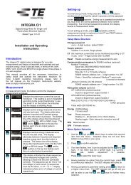
Setting Up4.3 Change Password1.2.3.Use the (up) and (down) to choose the Change Password option.Press to enter the change password routine. The New Password screenwill appear with the first digit flashing.Use and to set the first digit and press to confirm your selection.The next digit will flash.4. Repeat the procedure for the remaining three digits.5. After setting the last digit, SET will show.6.Press to exit the number setting routine and return to the Set-up menu.SET will be removed.4.4 Supply SystemUse this section to set the type of power supply being monitored.1.From the Set-up menu, use the (up) and (down) keys to select theSystem option. The screen will show the currently selected supply option.2.3.4.Pressflash.to enter the Supply Selection routine. The current selection willUse the (up)and (down) keys to select the required system option:or3-phase 4-wire 3-phase 3-wire Single phase.Pressto confirm your selection. SET indicator will appear.5.Press to exit the system selection routine and return to the menu. SET willdisappear and you will be returned to the main Set-up menu.10CI-3K50601 Project 2191 DMR2731 Rev.2 24-02-12
Setting Up4.5 dIT Demand <strong>Integra</strong>tion TimeThis sets the period in minutes over which the Current and Power readings are integrated formaximum demand measurement. The options are Off, 5, 8, 10, 15, 20, 30, and 60 minutes.1.From the Set-up menu, use the (up) and (down) keys to select thedIT option. The screen will show the currently selected integration time.2.Pressto enter the selection routine. The current time interval will flash.3.4.Use the (up) and (down) keys to select the required option from Off (nointegration time) to 60 minutes.Pressto confirm your selection. SET indicator will appear.5.Press to exit the dIT selection routine and return to the menu. The SETindicator will be removed and you will be returned to the main Set-up menu.4.6 CTThe CT option sets the maximum primary current (1 to 9999A) of the current transformer (CT) thatwill give 5A into the meter (the maximum).1.From the Set-up menu, use the (up) and (down) keys to selectthe CT option. The screen will show the current CT primary current value.An ‘A’ to the right of the lower line indicates that the reading is in amps.2.Presswill flash.to enter the CT primary current selection routine. The first digit3. Use the method described in Section 4.2.2 to set the 4-digit number to the maximum CTprimary current, e.g. 500A.4.to return to the main Set-On completion of the entry procedure, pressup menu.CI-3K50601 Project 2191 DMR2731 Rev.2 24-02-12 11
Setting Up4.7 RSET - ResetUse this option to restart Energy Hours (kWh, kVArh) and/or Current/Power Demandmeasurements from zero. These can be set individually or all together.1.2.From the main Set-up menu, use the (up) and (down) keys todisplay the Reset screen.Press. ‘dMd’ will flash.3.4.5.Use the (up) and (down) keys to select which counter(s) you wish to reset:Demand (dMd), Energy hours (hour), or both (ALL).Press to reset the selected counter. RSET will be displayed and theflashing will stop.Press to exit the Reset routine. RSET will clear and you will bereturned to the main Set-up menu.4.8 CommunicationsThe RS485 port can be used for communications using either Modbus or Johnson Controls (JC)N2 protocol. For Modbus, parameters such as Baud rate are selected from the front panelwhereas for JC N2 they are fixed. The RS485 address can be selected for both protocols.The first section allows you to select either Modbus or JC N2 configuration.1.From the main Set-up menu, use the (up) and(down) keys to display the Communications screen.2.Press . The Format screen will appear showing thecurrent format – Modb or N2.3.To change the format, press. The format will flash.4.Use the or key to change the format.5.Pressto confirm your selection. SET will be displayed.12CI-3K50601 Project 2191 DMR2731 Rev.2 24-02-12
Setting Up6.Pressremoved.to exit the format selection routine. SET will beIf you have selected N2 format, you can use the or key to select the RS485address option and set it as detailed on page 14.If you have selected ModB format, set the serial parameters as follows:7.Use the or key to cycle through the Baud, parity,stop bits and address menu options.Baud Rate (not applicable for JC N2)8. To change the Baud setting, ensure that the display shows the9.10.Baud setting and pressdigits will flash.to enter the setting routine. TheUse the and keys to select the desired Baud ratefrom the available options: 9600, 4800, 2400, 38.4k (38400)and 19.2k (19200).Pressdisplayed.to confirm your Baud rate selection. SET will be11.Pressandparameter.to exit Baud setting routine. SET will go off and thekeys can be used to select a different CommsParity (not applicable for JC N2)Note that if parity is set to Odd or Even, Stop Bits will be set to 1 and cannot be changed.12.Use the and keys to select the Parity option.13.Presswill flash.to enter the parity setting routine. The parameter14.Use the and keys to select the desired parity optionfrom None, Even and Odd.CI-3K50601 Project 2191 DMR2731 Rev.2 24-02-12 13
Setting Up15.Pressto confirm your selection. SET will be displayed.16.Pressto exit parity setting routine. SET will go off andthe and keys can be used to select a differentComms parameter.Stop Bits(not applicable for JC N2)Note that, if Parity is set to Odd or Even, Stop Bits will be set to 1 and cannot be changed.17.Use the and keys to select the Stop Bits option.18.19.Press to enter the Stop Bits setting routine. Theparameter value will flash.Use the and keys to select the desired number ofStop Bits – 1 or 2.20.Pressto confirm your selection. SET will be displayed.21.Pressto exit Stop Bits setting routine. SET will go off andthe and keys can be used to select a differentComms parameter.RS485 AddressAn RS485 network can accommodate up to 255 different devices, each identified by anaddress between 1 and 247 (Modbus) or 1 and 255 (JC N2).22.Use the and keys to select the Address option.23.Presswill flash.to enter the Address setting routine. The first digit24. Use the method described in Section 4.2.2 to set the 3-digitaddress to the required number between 1 and 247 forModbus or 1 and 255 for JC N2.14CI-3K50601 Project 2191 DMR2731 Rev.2 24-02-12
Setting UpModbus Word Order (not applicable for JC N2)This screen shows the word order (Hi/Lo) of the 8-bit bytes in theModbus message format. Normal is Hi first. This setting can only bechanged from the Modbus port. See the Cix Communications Guide forfurther information4.9 Pulse OutputThis option allows you to configure the pulse output. The output can be set to provide a pulse for adefined amount of energy imported or exported. The energy monitored can be active or reactiveand the pulse width can be selected as 200, 100 or 60 ms.The pulse rate output is limited to a maximum of two pulses per second. It is not possible to set anenergy-per-pulse that will result in a pulse rate that is greater than this. For example, on a singlephase,two-wire system, a CT setting of 900A with a maximum 289V supply implies a maximumenergy imported or exported in an hour of 900 x 289 = 260 kWh which is 72 W.seconds. A settingof 10Wh per pulse would generate 7 pulses per second. Since this exceeds 2/s, the unit would notallow such a setting.Use this section to set up the relay pulse output –Units Import kWh, export kWh, import kVArh, export kVArhRate 0.001/0.01/0.01/0.1/1/10/100/1k/10k kilo/pulsePulse width 200/100/60 ms.1.2.From the main Set-up menu, use the (up) and (down) keys todisplay the Relay screen.Press. The Relay Import/Export range screen will appear.3.4.Press to enter the Import/Export range selection routine. The displayedvalue will flash.Use the (up) and (down) keys to select the required option– noneor import/export and units.5.Pressto confirm your selection. SET will appear.6.Pressandto exit Output setting routine. SET will be removed and thekeys can be used to select a different Relay parameter.CI-3K50601 Project 2191 DMR2731 Rev.2 24-02-12 15
Setting UpRateUse this to set the energy represented by each pulse. Rate can be set to generate 1 pulse per0.001 = 1 Wh/VArh0.01 = 10 Wh/VArh0.1 = 100 Wh/VArh1 = 1 kWh/kVArh10 = 10 kWh/kVArh100 = 100 kWh/kVArh1k = 1 MWh/MVArh10k = 10 MWh/MVArhThe rate cannot be set to a value that could result in more than 2 pulses per second.7.Use the (up) and (down) keys to select the Rate screen.8.9.10.Press to enter the Rate setting routine. The Rate value willflash. The Rate is the energy that each output pulse represents.Use the (up) and (down) keys to select the Rate requiredfor the pulse output.Press to confirm your selection. The SET indicator will appearand the display will stop flashing.11.Pressto exit the Rate setting routine. The SET indicator will beremoved and the and keys can be used to select adifferent Relay parameter.Pulse DurationUse this option to set the duration of pulses (in ms). Pulse duration can be set to 60, 100 or 200ms.12.Use the (up) and (down) keys to select the Pulse screen.13.Pressflash.to enter the Pulse Width setting routine. The value will14.Use the (up) and (down) keys to select the Pulse Width inms.16CI-3K50601 Project 2191 DMR2731 Rev.2 24-02-12
Setting Up15.Press to confirm your selection. The SET indicator will appearand the display will stop flashing.16.Pressto exit Pulse Width setting routine. SET will disappearand the and keys can be used to select a different Relayparameter.4.10 Energy Units and 1% LimitUse this option to set the displayed energy units multiplier and to set a 1% limit on measuredenergy on or off.The unit multiplier can be set to Wh/VArh (x1), kWh/kVArh (kilo) or MWh/MVArh (Mega).To prevent noise from being recorded and causing ‘meter creep’, a 1% limit can be imposed on themeasured input such that energy readings less than 1% of maximum are not recorded. This limitcan be turned off so that even small energy increments are recorded.1.Use the (up) and (down) keys to select the Energyscreen.2.Pressto select the Energy menu.At this stage, you can use the and keys to select either the Energy Units or 1%Limit menu.Energy Units3.With the Unit screen selected, press to enter the Unitssetting routine. The currently selected unit flashes.4.5.Use the (up) and (down) keys to select the requiredunits: x1, kilo or Mega.Press to confirm your selection. SET will appear and thedisplay will stop flashing.CI-3K50601 Project 2191 DMR2731 Rev.2 24-02-12 17
Setting Up6.Pressto exit Units setting routine. SET will be removed.1% LimitWith the 1% Limit On, line noise below 1% of maximum power will be displayed as zero andwill not accrue to the energy reading. With Limit Off, the 1% symbol will be appear on thepower and energy screens to show that low power readings will be displayed and utilised.7.Use the (up) and (down) keys to select the Limitscreen.8.Pressto enter the Limit setting routine. The value will flash.9.10.Use the (up) and (down) keys to turn the 1% limit onor off.Press to confirm your selection. SET will appear and thedisplay will stop flashing.11.Pressto exit 1% Limit setting routine. SET will be removed.12.Press again to exit the Limit menu and return to the mainSet-up menu.4.11 TestThis option provides various test facilities.1.Use the (up) and (down) keys to select the Test screen.2.Pressto enter the Test menu.3.Use the and keys to select the required test option and press toconfirm your selection. The available options are:18CI-3K50601 Project 2191 DMR2731 Rev.2 24-02-12
Setting UpLights all LED segments so that display segments can bechecked.Pressto exit.Toggles display segments alternately.Pressto exit.Shows the voltage and current phase sequences.Pressto exit.4.Pressto exit the selected test display mode.5.Pressagain to return to the main Set-up menu.For the voltage and current phase sequence test to operate reliably, voltage and current inputsmust be greater than 5% of nominal.The Phase Sequence display shows the phase relationships of the supply voltages and currents.To obtain correct power, voltage and current readings, the indicated phase sequences should be‘123’.To obtain sequence test indications, the measured phase relationships must be within the followingparameters.Three-phase four-wire modeMeasurements are referenced from L1.Voltage:For the voltage sequence test, the phase of L2 relative to L1 must be within the window 240 +/-48 degrees and L3 relative to L1 must be within the window 120 +/- 48 degrees to record thesequence V123.Alternatively, the phase of L2 relative to L1 must be within the window 120 +/- 48 degrees andL3 relative to L1 must be within the window 240 +/- 48 degrees to record the sequence V132.The display shows ‘V1--‘ if a voltage phase is outside these parameters.Current:For the current sequence test, the phase of I1 relative to L1 must be within the window 0 +/- 48degrees and I2 relative to L1 must be within the window 240 +/- 48 degrees and I3 relative toL1 must be within the window 120 +/- 48 degrees to record the sequence i123.Alternatively the phase of I1 relative to L1 must be within the window 0 +/- 48 degrees and I2relative to L1 must be within the window 120 +/- 48 degrees and I3 relative to L1 must be withinthe window 240 +/- 48 degrees to record the sequence i132.CI-3K50601 Project 2191 DMR2731 Rev.2 24-02-12 19
SpecificationSetting UpThe display shows ‘I --‘ if a current phase is outside these parameters.]Three-phase three-wire modeMeasurements are referenced from L1-L2.Voltage:For the voltage sequence test, the phase of L2-L3 relative to L1-L2 must be within the window240 +/- 48 degrees and L3-L1 relative to L1-L2 must be within the window 120 +/- 48 degreesto record the sequence V123.Alternatively, the phase of L2-L3 relative to L1-L2 must be within the window 120 +/- 48degrees and L3 relative to L1-L2 must be within the window 240 +/- 48 degrees to record thesequence V132.The display shows ‘V1--‘ if a voltage phase is outside these parameters.Current:For the current sequence test, the phase of I1 relative to L1-L2 must be within the window 330+/- 48 degrees and I2 relative to L1-L2 must be within the window 210 +/- 48 degrees and I3relative to L1-L2 must be within the window 90 +/- 48 degrees to record the sequence i123.Alternatively, the phase of I1 relative to L1-L2 must be within the window 330 +/- 48 degreesand I2 relative to L1-L2 must be within the window 90 +/- 48 degrees and I3 relative to L1-L2must be within the window 210 +/- 48 degrees to record the sequence i132.The display shows ‘I --‘ if a current phase is outside these parameters.4.12 Version InformationThe last option of the Set-up menu show the versions of firmware and hardware of the unit. Usethe and keys to scroll through the Set-up menu options.Firmware version (2.51)Build (21.07)20CI-3K50601 Project 2191 DMR2731 Rev.2 24-02-12
Specification5 Specification5.1 Measured ParametersThe unit can monitor and display the following parameters of a single phase, 3-phase 3-wire or 3-phase 4-wire supply.5.1.1 Voltage and FrequencyPhase to neutral voltages 100 to 289V a.c. (not for 3p3w supplies)Voltages between phases 173 to 500V a.c. (3p supplies only)Frequency in HzPercentage total voltage harmonic distortion (THD%) for each phase to N (not for 3p3wsupplies)Percentage voltage THD% between phases (three phase supplies only)5.1.2 CurrentCurrent on each phase – 1 to 9999A range, set by external current transformer(s) (CTs)Neutral current (calculated) (three phase supplies only)Maximum demand currents on each phase, since the last Demand resetMaximum neutral demand current, since the last Demand reset (three phase supplies only)Current THD% for each phase5.1.3 Power and Power FactorInstantaneous power:Power 0 to 3600 MWReactive Power 0 to 3600 MVArVolt-amps 0 to 3600 MVAMaximum demanded power since last Demand resetPower factor5.1.4 Energy MeasurementsImported energy 0 to 9999999.9 Wh, kWh or MWhExported energy 0 to 9999999.9 Wh, kWh or MWhImported reactive energy 0 to 9999999.9 VArh, kVArh or MVArhExported reactive energy 0 to 9999999.9 VAhr, kVArh or MVArh5.2 Measured InputsVoltage inputs through 4-way fixed connector with 2·5mm 2 stranded wire capacity. 3-Phase 3- and4-wire and Single-phase 2-wire unbalanced. Line frequency measured from L1 voltage or L3voltage.Three current inputs (six physical terminals) with 2·5mm 2 stranded wire capacity for connection ofexternal CTs. Nominal rated input current 5A a.c. rms.CI-3K50601 Project 2191 DMR2731 Rev.2 24-02-12 21
Specification5.2.1 Range of UseValues of measured quantities, components of measured quantities, and quantities which affectmeasurement errors to some degree, for which the product gives meaningful readings.Voltage5 to 120% of Range Maximum (below 5% of range maximum voltage,current indication may only be approximate)Current1 to 120% of nominalPower factor 1 to 0, leading or laggingActive power 1 to 144% of nominal, 3600 MW maximumApparent power 1 to 144% of nominal, 3600 MVA maximumPower is only registered when voltage and current are within their respective range of use.Power factor is only indicated when the measured VA is over 3% of range maximum.5.3 AccuracyVoltage0·5% of range maximumCurrent0·5% of nominalNeutral current4% or nominal (calculated)Frequency0·2% of mid-frequencyPower factor 1% of unity (0.01)Active power (W)±1% of range maximumReactive power (VAr)±1% of range maximumApparent power (VA)±1% of range maximumActive energy (Wh) Class 1 IEC 62053-21Reactive energy (VARh) ±1% of range maximumTotal harmonic distortion 1% up to 31 st harmonicTemperature co-efficientResponse time to step inputError change due to variationof an influence quantity in themanner described in Section 6of IEC 688:1992Error in measurement when ameasurand is within itsmeasuring range, but outsideits reference rangeVoltage and current = 0.013%/°C typicalActive energy = 0·018%/°C, typical1s, typical, to >99% of final reading, at 50 Hz.2 error allowed for the reference condition applied in thetest. Error due to temperature variation as above.2 error allowed at the end of the reference range adjacentto the section of the measuring range, where themeasurand is currently operating / being tested.5.4 Auxiliary SupplyTwo-way fixed connector with 2·5mm 2 stranded wire capacity.110 to 400V a.c. 50/60Hz ±10% or 120V to 350V d.c. ±20%. Consumption < 10W.22CI-3K50601 Project 2191 DMR2731 Rev.2 24-02-12
Specification5.5 Interfaces for External MonitoringTwo interfaces are provided:• an RS-485 communication channel that can be programmed for Modbus (the default) orJohnson Controls (JC) N2 protocol• a relay output indicating real-time measured energy.The Modbus configuration (Baud rate etc.) and the pulse relay output assignments (kW/kVArh,import/export etc.) are configured through the Set-up screens.5.5.1 Pulse Relay OutputThe pulse relay output can be set to generate pulses to represent imported kWh, exported kWh,imported kVArh or exported kVArh.Rate can be set to generate 1 pulse per:0.001 = 1 Wh/VArh0.01 = 10 Wh/VArh0.1 = 100 Wh/VArh1 = 1 kWh/kVArh10 = 10 kWh/kVArh100 = 100 kWh/kVArh1k = 1 MWh/MVArh10k = 10 MWh/MVArhThe rate cannot be set to a value that could result in more than 2 pulses per second.Pulse width 200/100/60 ms.Relay Rating 240V ac 50mA5.5.2 RS485 Output for Modbus or JC N2 ProtocolFor Modbus, the following RS485 communication parameters can be configured from the Set-upmenu:Baud rate 2400, 4800, , 9600, , 19200, 38400Parity none/odd/evenStop bits 1 or 2RS485 network address nnn – 3-digit number, 1 to 247Modbus Word order Hi/Lo byte order is set automatically to normal or reverse. It cannotbe configured from the set-up menu.Note that with odd or even parity set, Stop Bits are forced to one.For JC N2, only the RS485 network address can be configured. The range of addresses is 1-255.CI-3K50601 Project 2191 DMR2731 Rev.2 24-02-12 23
5.6 Reference Conditions of Influence QuantitiesInfluence Quantities are variables that affect measurement errors to a minor degree. Accuracy isverified under nominal value (within the specified tolerance) of these conditions.Ambient temperature23°C ±1°CInput waveform 50 or 60Hz ±2%Input waveform Sinusoidal (distortion factor < 0·005)Auxiliary supply voltage Nominal ±1%Auxiliary supply frequency Nominal ±1%Auxiliary supply waveform (if AC) Sinusoidal (distortion factor < 0·05)Magnetic field of external origin Terrestrial flux5.7 EnvironmentOperating temperature -10°C to +55°C *Storage temperature -20°C to +70°C *Relative humidity 0 to 90%, non-condensingAltitudeUp to 2000mWarm up time1 minuteVibration10Hz to 50Hz, IEC 60068-2-6, 2gShock30g in 3 planes* Maximum operating and storage temperatures are in the context of typical daily and seasonalvariation.5.8 MechanicsDIN rail dimensions 72 x 90 mm (WxH) per DIN 43880Mounting DIN rail (DIN 43880)SealingIP20 (minimum)Material Self-extinguishing UL 94 V-05.9 Approval, Certification, and Standards ComplianceRoHS compliant. (Although this class of product is presently excluded from the RoHS regulations,the unit has been designed and manufactured in compliance with the RoHS regulations.)EMC Emissions BS EN 61326, Class A (Industrial)EMC Immunity BS EN 61326, Class A (Industrial)Safety BS EN 61010-1:200124CI-3K50601 Project 2191 DMR2731 Rev.2 24-02-12
Maintenance6 MaintenanceWarningDuring normal operation, voltages hazardous to life may be present at some of theterminals of this unit. Installation and servicing should be performed only by qualified,properly trained personnel abiding by local regulations. Ensure all supplies are deenergisedbefore attempting connection or other procedures.Terminals should not be user accessible after <strong>installation</strong> and external <strong>installation</strong>provisions must be sufficient to prevent hazards under fault conditions.This unit is not intended to function as part of a system providing the sole means offault protection - good engineering practice dictates that any critical function beprotected by at least two independent and diverse means. This unit does not have internal fuses, therefore external fuses must be used forprotection and safety under fault conditions.In normal use, little maintenance is needed. As appropriate for service conditions, isolate fromelectrical power, inspect the unit and remove any dust or other foreign material present.Periodically check all connections for freedom from corrosion and screw tightness, particularly ifvibration is present.The front of the case should be wiped with a dry cloth only. Use minimal pressure, especially overthe viewing window area. If necessary wipe the rear case with a dry cloth. If a cleaning agent isnecessary, isopropyl alcohol is the only recommended agent and should be used sparingly. Watershould not be used. If the rear case exterior or terminals should be contaminated accidentally withwater, the unit must be thoroughly dried before further service. Should it be suspected that watermight have entered the unit, factory inspection and refurbishment is recommended.In the unlikely event of a repair being necessary, it is recommended that the unit be returned to thefactory or nearest TE Connectivity/<strong>Crompton</strong> <strong>Instruments</strong> service centre.CI-3K50601 Project 2191 DMR2731 Rev.2 24-02-12 25
Installation7 InstallationThe unit is intended for mounting on a standard DIN rail. Hook the unit onto the top of the rail andpress the bottom of the unit until it locks in place. To remove the unit from the rail, lever down theblack tab at the bottom of the unit to release it from the rail.The unit is intended for use in a reasonably stable ambient temperature within the range -10 to+55°C. Do not mount the unit where there is excessive vibration or in excessive direct sunlight.WarningDuring normal operation, voltages hazardous to life may be present at some of theterminals of this unit. Installation and servicing should be performed only by qualified,properly trained personnel abiding by local regulations. Ensure all supplies are deenergisedbefore attempting connection or other procedures.Terminals should not be user accessible after <strong>installation</strong> and external <strong>installation</strong>provisions must be sufficient to prevent hazards under fault conditions.This unit is not intended to function as part of a system providing the sole means offault protection - good engineering practice dictates that any critical function beprotected by at least two independent and diverse means.The unit does not have internal fuses therefore external fuses must be used forprotection and safety under fault conditions.Never open-circuit the secondary winding of an energized current transformer.This product should only be operated with the CT secondary connections Earthed.If this equipment is used in a manner not specified by the manufacturer, protectionprovided by the equipment may be impaired.Auxiliary circuits (communication & relay outputs) are separated from metering inputsand 110-400V auxiliary circuits by at least basic insulation. Such auxiliary circuitterminals are only suitable for connection to equipment which has no user accessiblelive parts. The insulation for such auxiliary circuits must be rated for the highest voltageconnected to the instrument and suitable for single fault condition. The connection atthe remote end of such auxiliary circuits should not be accessible in normal use.Depending on application, equipment connected to auxiliary circuits may vary widely.The choice of connected equipment or combination of equipment should not diminishthe level of user protection specified.7.1 SafetyThe unit was designed in accordance with BS EN 61010-1:2001 (IEC 61010-1:2001) –Permanently connected use, Normal condition. Installation category III, pollution degree 2, basicinsulation for rated voltage. Measurement Category III.7.2 EMC Installation RequirementsWhilst this unit complies with all relevant EU EMC (electro-magnetic compatibility) regulations,additional precautions necessary to provide proper operation of this and adjacent equipment will be<strong>installation</strong> dependent and so the following can only be general guidance:Avoid routing wiring to this unit alongside cables and products that are, or could be, a source ofinterference.26CI-3K50601 Project 2191 DMR2731 Rev.2 24-02-12
InstallationThe auxiliary supply to the unit should not be subject to excessive interference. In some cases,a supply line filter may be required.To protect the product against incorrect operation or permanent damage, surge transients mustbe controlled. It is good EMC practice to suppress transients and surges at the source. The unithas been designed to automatically recover from typical transients; however in extremecircumstances it may be necessary to temporarily disconnect the auxiliary supply for a periodof greater than 5 seconds to restore correct operation.Screened communication leads are required. These and other connecting leads may requirethe fitting of RF suppression components, such as ferrite absorbers, line filters etc., if RF fieldscause problems.It is necessary to wind the three current inputs through separate ferrite rings, example partnumber Würth Elektronik 742 701 110, a minimum of 6 times.It is good practice to install sensitive electronic instruments that are performing critical functionsin EMC enclosures that protect against electrical interference causing a disturbance in function.7.3 Case DimensionsI7.4 WiringInput connections are made to screw clamp terminals. Choice of cable should meet localregulations for the operating voltage and current.The current inputs of these products are designed for connection into systems via currenttransformers only.All negative current inputs are commoned inside the unit and grounding should be at one pointonly.To minimise measurement errors, the CTs should be grounded as shown in the wiring diagram inSection 7.8.CI-3K50601 Project 2191 DMR2731 Rev.2 24-02-12 27
InstallationCT secondaries must be grounded in accordance with local regulations. It is desirable to makeprovision for shorting links to be made across CTs to permit easy replacement of a unit should thisever be necessary.7.4.1 Additional considerations for three wire systemsThe neutral terminal (terminal N) is indirectly connected to the voltage input terminals (terminalsL1, L2, L3). When connected to a three wire system the neutral terminal will adopt a potentialsomewhere between the remaining lines.If external wiring is connected to the neutral terminal it must be connected to either the neutral lineor earth (ground) to avoid the possibility of electric shock from the neutral terminal.7.5 Auxiliary SupplyThe <strong>Integra</strong> <strong>Ri3</strong> should ideally be powered from a dedicated supply; however it may be poweredfrom the signal source providing the source will always be within tolerance for the auxiliary supplyvoltage range.Requirements: 110 to 400Va.c. 50/60Hz ±10% or 120V to 350Vd.c. ±20%. Consumption
InstallationVoltage lines and auxiliary supply must be fused - see above.7.9 RS485 and Modbus or JC N2 ProtocolThe RS485 interface in conjunction with the Modbus or JC N2 protocol allows the unit to beinterrogated and provide a response detailing the readings it has taken. This can be used forremote monitoring by a PC or SCADA system.An RS485 and Modbus Protocol Guide is available for download from the <strong>Crompton</strong> <strong>Instruments</strong>web site at http://www.crompton-instruments.com/ci_range/Ci1_Ci3_Comms_guide.pdf7.10 Operation CheckAfter <strong>installation</strong>, use the test display to check for incorrect wiring of the voltage andcurrent transformer inputs (see Section 4.11). The displayed voltage (V) and current (I)sequences must be ‘123’ to obtain the correct power, voltage and current readings.In the event of a voltage phase error, e.g. the same phase connected to two meter inputs, thedisplay will show ‘V1--‘.In the event of a current phase error, e.g. a current transformer connected the wrong way round orto the wrong phase, the display will read ‘I --‘.If the display shows the correct V and I sequence (123), check that the meter shows correctly thatenergy is being imported or exported. An incorrect import/export indication means that all currenttransformers are connected the wrong way round.The meter has a certain tolerance in order to correctly identify phase errors, as described inSection 4.11.CI-3K50601 Project 2191 DMR2731 Rev.2 24-02-12 29
Glossary8 GlossaryActive energyCTFirmwareJohnson Controls(JC) N2ModbusReactive energyRS485SCADAAccumulated energy (Watt hours).Current Transformer. Transforms a (usually) high current to a valuethat can be monitored by the meter.Software installed on a permanent medium.A master - slave serial communication protocol with fixedcommunication parameters.A proprietary communications protocol used for control and monitoring.The energy (VArh) in the reactive component of the supply. Thecurrent and voltage in the reactive component are mutually 90 out ofphase - capacitive or inductive – resulting in a supply power factor ofzero.A serial communication system linking multiple addressed terminals.Supervisory Control And Data Acquisition system.30CI-3K50601 Project 2191 DMR2731 Rev.2 24-02-12
Index9 Index1% limit, 17, 18Address, 14, 23Auxiliary supply, 22, 28Baud rate, 13, 23Blue man symbol, 7Certification, 24Connections, 27CT, 5, 11CT earth, 28CT primary current, 5, 6, 11Current readings, 7Current transformer, 5, 11, 28Demand integration time, 11Demand reset, 12Displayed units, 17Divisors, 16EMC, 24, 26Energy readings, 7Energy reset, 12Energy units, 17Error, 22Firmware version, 6Frequency reading, 6Fuses, 28Hours reset, 12Inputs, 21JC N2, 5, 12Johnson Controls, 5, 12LED check, 19Limit, 17, 18Maintenance, 25Maximum demand, 7Meter creep, 17Meter current, 11Modbus, 5, 12, 23, 29Multiplier, 17Noise, 17Number entry, 9Parity, 13, 23Password, 10Phase sequence, 19Power factor, 7Power readings, 7Pulse duration, 16Pulse output, 6, 15, 23Pulse rate, 15, 16Pulse width, 15, 16, 23Range maximum, 22Reset, 12RoHS, 24RS485, 5, 23RS485 address, 14Safety, 26Screen check, 6SET indicator, 9Size, 27Standards, 24Start Up Screens, 6Stop bits, 14, 23Supply selection, 10, 11Temperature, 24, 26Test, 6, 18THD%, 7Units, 17Version information, 20Voltage readings, 6CI-3K50601 Project 2191 DMR2731 Rev.2 24-02-12 31
IndexWhile TE Connectivity (TE) has made every reasonable effort to ensure the accuracy of the information in thismanual, TE does not guarantee that it is error-free, nor does TE make any other representation, warranty orguarantee that the information is accurate, correct, reliable or current. TE reserves the right to make anyadjustments to the information contained herein at any time without notice. TE expressly disclaims all impliedwarranties regarding the information contained herein, including, but not limited to, any implied warranties ofmerchantability or fitness for a particular purpose. The dimensions in this document are for reference purposesonly and are subject to change without notice. Specifications are subject to change without notice. Consult TEfor the latest dimensions and design specifications. TE connectivity (logo) and TE Connectivity are trademarksof the TE Connectivity Ltd. family of companies. Other logos, product and company names mentioned hereinmay be trademarks of their respective owners. <strong>Crompton</strong> is a trademark of <strong>Crompton</strong> Parkinson and is used byTE Connectivity under licence.Tyco Electronics (UK) Ltd.Freebournes Road,WithamEssex CM8 3AHEnglandTel: +44 (0) 1376 509509Fax: +44 (0) 1376 509511www.crompton-instruments.comwww.energy.te.com32Registered office:Faraday Road, DorcanSwindon, SN3 5HHReg. no. 550 926CI-3K50601 Project 2191 DMR2731 Rev.2 24-02-12