PC20700 ACO StormTank Brochure Update Jan 10:Layout 1 - NMBS
PC20700 ACO StormTank Brochure Update Jan 10:Layout 1 - NMBS
PC20700 ACO StormTank Brochure Update Jan 10:Layout 1 - NMBS
You also want an ePaper? Increase the reach of your titles
YUMPU automatically turns print PDFs into web optimized ePapers that Google loves.
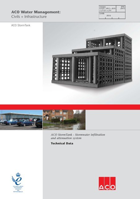
<strong>ACO</strong> Water Management:Civils + InfrastructureUniclassL2123 + JR12 + JS<strong>10</strong>+ L71121 + L731CI/SfB(52.5)EPICJ3413<strong>ACO</strong> <strong>StormTank</strong><strong>ACO</strong> <strong>StormTank</strong> - Stormwater infiltrationand attenuation systemTechnical Data
ATTENUATION SYSTEMAttenuation is the process of spreadingthe peak flow of a storm event over alonger period of time, releasing the waterslowly, and mitigating the surge effectdownstream.The modular construction of the <strong>ACO</strong><strong>StormTank</strong> system allows the engineer todesign a water storage structure capableof withstanding traffic loads, controllingand managing sediment build up whilsttaking into account site conditions.Similar to the <strong>ACO</strong> <strong>StormTank</strong> infiltrationsystem, side panels are placed into the<strong>ACO</strong> <strong>StormTank</strong> units at the perimeter ofthe system configuration, wrapped with awatertight geomembrane and thencovered with a protection fleece.Additional side panels and non-wovengeotextile can be incorporated within thestructure to create a sedimentcontainment tunnel, that directs the ‘firstflush’ of any storm straight through thesystem to a downstream manhole wherelarger debris can be captured andremoved. This alleviates the possibility ofthe system becoming blocked by ensuringsediment cannot be contained within thesystem in the long term. A typicalinstallation of an attenuation system isshown in the diagram below and furtherdetails can be found on page 19.The addition of inspection pipes at theperimeter allows the <strong>ACO</strong> <strong>StormTank</strong>system to be inspected with remote CCTVequipment, thereby greatly assisting thepossibility of the system being adopted bya relevant authority.A typical example of an attenuation system<strong>ACO</strong>Tex Plus protection fleeceGeomembraneOutlet pipe5Side panel<strong>ACO</strong>Tex lined sediment tunnelInlet pipe
<strong>ACO</strong> <strong>StormTank</strong>Technical Data<strong>ACO</strong> <strong>StormTank</strong> overviewACCESSORIES AND OPTIONSPipe connectorsSide panelsVertical connectors<strong>ACO</strong> <strong>StormTank</strong> has arange of U-PVC pipeconnectors available toprovide connection tounderground drainagepipework. Standardfeatures include inlet /outlet connection forØ1<strong>10</strong>mm, Ø160mm,Ø225mm and Ø300mmpipes and flanged platesto aid connection to the<strong>ACO</strong> <strong>StormTank</strong> system.Ø160mm pipe connector<strong>ACO</strong> <strong>StormTank</strong> has arange of recyclablepolypropylene side wallpanels, which inconjunction with <strong>ACO</strong>Tex,may also be used withinthe internal structure ofthe configuration to form asediment forebay or tunnelto control sediment buildup within the system.See pages 4, 5, and 19for further details.Polypropyleneside panelA U-PVC vertical connectorfor <strong>ACO</strong> <strong>StormTank</strong> isavailable to help withalignment and installationof the system.See page <strong>10</strong> for furtherdetails.Manufactured from recyclablepolypropylene6Available in three sizesLightweight design
Geotextiles<strong>ACO</strong>TexA polypropylene permeable non-wovengeotextile for installations that requireinfiltration control methods to allow thepassage of water into and out of <strong>ACO</strong><strong>StormTank</strong> systems, and also to preventthe entry of sediment into systemsincorporating sediment forebays.See pages 11 and 12 for further detailsand specifications.Protection fleece<strong>ACO</strong>Tex PlusManufactured from polypropylene this thicknon-woven protection fleece is used toprotect a geomembrane from mechanicaldamage due to ground and thermalmovement. The protection fleece is placedon the outer side of the geomembrane.<strong>ACO</strong>Tex Plus can be used with <strong>ACO</strong>Wrapor with a welded geomembrane system.See pages 11 and 12 for further detailsand specifications.Geomembranes<strong>ACO</strong>WrapAn impermeable self-install geomembraneusing taped joints for ‘non sensitive’attenuation applications (refer to page 11for further information).For sensitive applications <strong>ACO</strong> recommendthe <strong>ACO</strong> <strong>StormTank</strong> system is installed by<strong>ACO</strong> recommended lining contractors usinga geomembrane system with welded<strong>10</strong>0% watertight joints (refer to page 13).Please consult <strong>ACO</strong> Design Services for alist of recommended contractors and forfurther advice and guidance.See pages 11 and 12 for further detailsand specifications.High void ratio – 95-97%Strong, tough, highlycorrosion resistant structureSystem is open on allsides but has optionalextra side wall panels forthe use at the perimeterof any tank configuration7Strong, rigid support columnsmanufactured from U-PVC
<strong>ACO</strong> <strong>StormTank</strong>Technical DataTechnical data<strong>ACO</strong> <strong>StormTank</strong> unitsProductcode27003Description<strong>ACO</strong> <strong>StormTank</strong> FC4Length(mm)914Widthoverall(mm)457Depthoverall (mm)457Gross storagevolume m³0.191Nett storageVolume m³0.18VoidRatio95Weight(kg)9.3Verticalcompressivestrength kN/m²340Lateralcompressivestrength kN/m²14027002<strong>ACO</strong> <strong>StormTank</strong> FC69144576<strong>10</strong>0.2540.2496<strong>10</strong>.53405627000<strong>ACO</strong> <strong>StormTank</strong> FC9 †9144579140.3820.379713.034034914mm914mm914mm457mm457mm457mm457mm6<strong>10</strong>mm914mmFC4 unit FC6 unit FC9 unit<strong>ACO</strong> <strong>StormTank</strong> side panelsProduct code27013DescriptionSide panel for <strong>ACO</strong> <strong>StormTank</strong> FC4Length (mm)395Width overall(mm)442Depthoverall (mm)28Weight (kg)0.8227012Side panel for <strong>ACO</strong> <strong>StormTank</strong> FC6547442281.00270<strong>10</strong>Side panel for <strong>ACO</strong> <strong>StormTank</strong> FC9 †851442281.528395mm547mm851mm442mm442mm442mm28mm28mm28mmFC4 side panel FC6 side panel FC9 side panelNote: For information on side wall functionalty see page <strong>10</strong>† For use in landscaped areas only.
<strong>ACO</strong> <strong>StormTank</strong> inlet / outlet pipe & vertical connectorsProduct code27020DescriptionØ1<strong>10</strong>mm pipe connector with flangeLength (mm)-Width overall(mm)Ø1<strong>10</strong>Depthoverall (mm)-Weight (kg)0.7527021Ø160mm pipe connector with flange-Ø160-1.2527022Ø225mm pipe connector with flange-Ø225-1.4027023Ø300mm pipe connector with flange-Ø300-1.7527030Vertical connectors----<strong>10</strong>5mm2<strong>10</strong>mm<strong>10</strong>5mm200mm144mm130mm260mm130mm200mm144mm2<strong>10</strong>mmØ1<strong>10</strong>mm260mmØ160mmØ1<strong>10</strong>mm pipe connectorØ160mm pipe connector365mm182.5mm365mm182.5mm200mm154mm440mm220mm395mm197.5mm240mm219mmØ225mmØ225mm pipe connectorØ300mmØ300mm pipe connector<strong>ACO</strong> <strong>StormTank</strong> geotextiles9Product code27040Description<strong>ACO</strong>Tex infiltration geotextileLength (m)<strong>10</strong>0Width overall(m)4.5Thickness(mm)1.0Mass per unitarea (g/m 2 )125Weight (kg)57 per roll27041<strong>ACO</strong>Tex Plus protection fleece<strong>10</strong>042.9325130 per roll* <strong>ACO</strong> <strong>StormTank</strong> geotextiles listed above sold per roll. For information on functionality see page 11 and for specification and performance data see page 12.<strong>ACO</strong> <strong>StormTank</strong> geomembranes and accessoriesProduct code27042Description<strong>ACO</strong>WrapLength (m)12.5Nominal widthoverall (mm)4 (m)Thickness(mm)0.45Mass per unitarea (g/m 2 )460Weight (kg)23.027044<strong>ACO</strong> double sided butyl mastic tape15<strong>10</strong>01.5-3.7027045Ø1<strong>10</strong> flexible top hat-Ø<strong>10</strong>00.9-0.<strong>10</strong>27046Ø160 flexible top hat-Ø1500.9-0.<strong>10</strong>27047Ø225 flexible top hat-Ø2250.9-0.<strong>10</strong>27048Ø300 flexible top hat-Ø 3000.9-0.<strong>10</strong>* <strong>ACO</strong> <strong>StormTank</strong> geomembranes and accessories listed above sold per roll. For information on functionally see page 11 and for specification and performance data see page 12.
<strong>ACO</strong> <strong>StormTank</strong>Technical Data<strong>ACO</strong> <strong>StormTank</strong> accessories - features, functions and benefitsPipe connectorsA range of U-PVC flanged pipeconnectors in Ø1<strong>10</strong>mm, Ø160mm,Ø225mm and Ø300mm is available toprovide connection between the <strong>ACO</strong><strong>StormTank</strong> system and the undergrounddrainage network. The method ofconnection is described below:Adding side panelsEach size of the <strong>ACO</strong> <strong>StormTank</strong> systemhas side panels available to providelateral support to the perimeter of thesystem where soil pressure will be adesign consideration. The side panelscan also be used within the <strong>ACO</strong><strong>StormTank</strong> system to create: A sediment forebay A sediment tunnel<strong>ACO</strong> <strong>StormTank</strong> is supplied assembledwithout side panels. The method ofincluding side panel to the units isdescribed below:Vertical connectorsVertical connectors are available foruse during installation to help withthe alignment of the units in multipledepth designs.Ø1<strong>10</strong>mmØ160mmØ225mmØ300mmVertical connectorUnit with side panelFUNCTIONS: FUNCTIONS: FUNCTIONS:<strong>10</strong>Step 1: Using a holesaw or jigsaw cut theappropriate diameterhole in the side panelof the <strong>ACO</strong><strong>StormTank</strong> unit tothe correct invertlevel. Ensure that theflange of the pipeconnector does notprotrude below theinvert of the tank.Step 2: Fix theconnector to theside panel by usingcable ties throughthe holes at thecorners of theflange. Ensure thatthe pipe connectoris fitted so thatthere is adequatespigot for thejoining pipework toconnect to.Step 3: Thegeomembrane orgeotextile is thenadhered to theflange by anappropriate methodto give a firm seal.Step 1: Tap gentlywith a rubber malletat each edge of thetop plate to loosenfrom the mainframe. Remove toppanel.Step 2: Push fit theside panel into theslot provided in thebase plate. Twoside panels arerequired on eachlength of the unitand one side panelfor each end.Step 3: Place topplate into positionover the unit. Tapfirmly down on thetop plate to pushback onto the <strong>ACO</strong><strong>StormTank</strong> unit.Step 1: Place avertical connectorinto each circularrecess on the toppanel of the <strong>ACO</strong><strong>StormTank</strong> system.Step 2: The nextlayer of the <strong>ACO</strong><strong>StormTank</strong> systemcan now be added.The verticalconnectors willaid the installationand alignment ofmultiple depthdesigns.
Material application guideInfiltration<strong>ACO</strong>TexAttenuation<strong>ACO</strong>Tex Plus<strong>ACO</strong>Wrap orweldedgeomembranerefer to p14Double sidedbutyl mastic tapeFlexible top hatGeotextiles<strong>ACO</strong>TexA non-woven polypropylene geotextile withexcellent filtration and drainage propertiesused to minimise sediment build up withinan <strong>ACO</strong> <strong>StormTank</strong> infiltration (soakaway)or attenuation system. The <strong>ACO</strong>Texcompletely envelops the <strong>ACO</strong> <strong>StormTank</strong>system as well as the sediment forebay ortunnel where specified.Protection fleece<strong>ACO</strong>Tex PlusA heavy duty non-woven protection fleeceused to protect a geomembrane againstpuncture on an <strong>ACO</strong> <strong>StormTank</strong>attenuation system. The <strong>ACO</strong>Tex Pluscompletely envelops the <strong>ACO</strong> <strong>StormTank</strong>system and geomembrane. <strong>ACO</strong>Tex Plusmay be used with <strong>ACO</strong>Wrap and anyother geomembrane system.Pipe ConnectorPipe ConnectorGEOMEMBRANES<strong>ACO</strong>Wrap<strong>ACO</strong>Wrap is a self-install tapedgeomembrane system to be used onlywhere ground conditions are suitable suchthat minor leakage from the tank isacceptable.<strong>ACO</strong> is also able to recommend awarranty backed fully weldedgeomembrane and installation servicethrough independent lining contractors.Recommended welded geomembranespecifications are detailed on page 12.Top Hats: Flexible membrane pipeconnectors used in conjunction with<strong>ACO</strong>Wrap to form pipe seals (see page 9for details).11<strong>ACO</strong>Wrap should NOT be used insensitive applications such as: Within 5m of any building line Where there is a high water table Where land is contaminated or therisk of contamination from surfacewater is high.Please consult the <strong>ACO</strong> Design ServicesTeam on 01462 816666 for furtheradvice.Please consult the <strong>ACO</strong> Design ServicesTeam on 01462 816666 for further advice.Accessories for <strong>ACO</strong>Wrap include:Tape: A double sided butyl mastic tapeused to join sheets of <strong>ACO</strong>Wrap (Productcode 27044, see page 9 for details).
<strong>ACO</strong> <strong>StormTank</strong>Technical Data<strong>ACO</strong> <strong>StormTank</strong> geotextiles and geomembranes:specification and performance data<strong>ACO</strong>Tex infiltration geotextileProduct codeDescriptionMaterialSheet dimensionsMaterial thickness (for 2 kPa)Material mass per unit areaCBR puncture resistanceStrip tensile strength (md)(cd)Elongation at maximum loadCone drop testUnitLength (m)Width (m)(mm)(g/m²)(N)kN/mkN/m(md)(cd)(mm)27040Mechanically bonded continuous filament non-woven sheet<strong>10</strong>0% UV stabilised polypropylene<strong>10</strong>04.5112515009<strong>10</strong>90%65%24Opening size µm<strong>10</strong>5Permeability verticall/m²/s115<strong>ACO</strong>Wrap geomembraneProduct codeDescriptionMaterialSheet dimensionsMaterial mass per unit areaUnitLength (m)Width (m)(g/m²)2704212.5446012ColourBlack<strong>ACO</strong>Tex Plus protection fleeceProduct codeDescriptionMaterialSheet dimensionsMaterial thickness (for 2 kPa)Material mass per unit areaCBR puncture resistanceStrip tensile strength (md)(cd)Elongation at maximum loadCone drop testUnitLength (m)Width (m)(mm)(g/m²)(N)kN/mkN/m(md)(cd)(mm)27041Mechanically bonded continuous filament non-woven sheet<strong>10</strong>0% UV stabilised polypropylene<strong>10</strong>042.932538502424<strong>10</strong>0%40%15Opening size µm90Permeability verticall/m²/s60
Design guidanceEarly consideration needs to be given tothe issue of adoption and maintenance ofany Sustainable Drainage System (SUDS).Consultation should occur with therelevant planning or adopting authority atthe outset in order to determine theirpolicy on the adoption of SUDS, as thismay fundamentally affect the choice ofSustainable Drainage System available.The local authority, highways authorityand water authority all have powers toadopt <strong>ACO</strong> <strong>StormTank</strong> systems whereappropriate, and therefore earlyconsultation with the relevant authority isstrongly advised.To design and construct an <strong>ACO</strong><strong>StormTank</strong> system specifiers need toconsider three major factors: Hydraulic Design Structural Design MaintenanceHydraulic design looks at the temporarystorage of water in storm events and itsflow path, seeking to reduce the volume,speed, and frequency of surface water runoff. All of these factors will be site specific.Calculations for hydraulic design should beunder-taken using the methods highlightedin CIRIA C697 The SUDS Manual.Structural design is needed to considerthe load bearing capacity of the <strong>ACO</strong><strong>StormTank</strong> system so that it can safelycarry the loads it will be subjected to.Design of the system therefore firstlyneeds to decide whether to infiltrate orattenuate, and then to consider: Soil type Vertical and horizontal loading Groundwater Depth of cover Surface finishTESTINGProduct performance tests carried out on<strong>ACO</strong> <strong>StormTank</strong> have been conductedusing the methods recommended inCIRIA C680 “Structural design ofmodular geocellular drainage tanks”.Data supplied can be supported byqualified third party independentcertification.Ultimate load bearing capacity has beenestablished under laboratory testingconditions during short term load testing.Partial factor of safety of 2.75 (ultimatelimit state) and 1.5 (serviceability limitstate) should be applied to these valuesfor a 20 year design life.Design should also consider the long termmaintenance and accessibility of theSUDS system. <strong>ACO</strong> <strong>StormTank</strong> with theincorporation of a sediment forebay orsediment tunnel as appropriate cancontrol sediment build up within thesystem (refer to p19) and ensure thesystem remains accessible for inspection.<strong>ACO</strong> Design Services TeamPlease contact the <strong>ACO</strong> Design ServicesTeam on 01462 816666 for advicewhen designing <strong>ACO</strong> <strong>StormTank</strong> schemes.The <strong>ACO</strong> Design Services Team will bepleased to assist with any technicalqueries, scheme designs or partsschedules.13Cover depthsApplicationMinimum required depthLandscaping or Pedestrian 0.5mCars up to 2500kg 0.85mVehicles over 2500kgPlease consult the <strong>ACO</strong> Design Services TeamIt is possible to accommodate more difficult or complex site conditions – please consult the <strong>ACO</strong> Design Services Team for further advice.For physical properties of <strong>ACO</strong> <strong>StormTank</strong>, please refer to page 8
<strong>ACO</strong> <strong>StormTank</strong>Technical DataGeomembrane selectionThe correct choice of geomembrane isessential to the overall performance ofany attenuation system.In applications where there are sitesensitive issues, a geomembrane withproperties similar to those outlined in thetable below should be used and installedby a lining contractor with UKCAS CSWIPaccreditation.Site Sensitive applications include, butare not limited to: High groundwater table. Contaminated ground. Within 5m of any building line. Where there is a risk ofcontamination to groundwater frompolluted surface waters.Only in applications where minor leakagefrom the attenuation system is acceptableshould the <strong>ACO</strong>Wrap system be used.Please consult <strong>ACO</strong> Design Services Teamfor further information or advice.Welded geomembrane: recommended specificationTested PropertyUnitTest MethodMinimum Values*Thickness**mmASTM D 51991.0Density (max)g/cm 3ASTM D 792 / 1505A≤ 0.939Tensile properties (each direction)ASTM D 6693, Type IV, Speed: 50mm/minStrength at breakN/mm 227Elongation at break%G.L. = 50mm800Tear resistanceNASTM D <strong>10</strong>04<strong>10</strong>0Puncture resistanceNASTM D 4833250Carbon black content%ASTM D 16032.0Carbon black dispersionCategoryASTM D 55961/2†* Value at 95% confidence interval** Average value of <strong>10</strong> specimens taken across roll width. No value to be less than 90% of average value.† Dispersion only applies to near spherical agglomerates. 9 of <strong>10</strong> views should be category 1 or 2. No more than 1 view from category 3.14
Installation detailsInstallation steps for <strong>ACO</strong><strong>StormTank</strong> infiltration systemsGeneral adviceThe <strong>ACO</strong> <strong>StormTank</strong> units should beinstalled in accordance with theinstallation instructions and relevantlegislation. Special attention should bepaid to temporary work requirements inexcavations.Step 1Excavate the pipe trench and lay the inletpipe to the required fall and invert level,install silt traps in appropriate locations inthe pipe run.Step 5Ensure that ground bearing capacity atformation level is adequate for designloads. Remove any soft spots from theexcavation and replace with compactedgranular material.Step 6Lay <strong>10</strong>0mm coarse sand bedding to thebase of the excavation and level. Forinfiltration applications use coarse sandor class 6H selected granular materialin accordance with the Manual ofContract Documents for Highway Works(MCHW) Volumes 1 & 2. It is essentialthat the bedding layer is correctlylevelled and smooth.Step 7Lay the geotextile, to the specification onpage 12, over the sand bedding and upthe sides of the excavation with minimum300mm overlap joints between strips.Step <strong>10</strong>Where a sediment forebay has beendetailed, form the forebay containmentstructure around the pipe inlet using sidepanels on the correct modules to thedimensions specified and encapsulateusing <strong>ACO</strong>Tex.Step 11Form the remainder of the <strong>ACO</strong><strong>StormTank</strong> modules to the overalldimensions specified.Step 2Excavate the hole or trench to the requireddimensions to receive the <strong>ACO</strong> <strong>StormTank</strong>modular units, and any external inspectionchamber(s) and/or silt trap(s).Step 3Ensure that the base plan dimensions of thehole allow 300mm working space on allsides for the site operatives to manoeuvrethe <strong>ACO</strong> <strong>StormTank</strong> units and geotextile intoposition. Ideally mark out the plan area withspray paint or chalk line.Step 4Ensure that the base of the excavation issmooth and level, batter back the sides ofthe excavation to a safe angle, andensure that safe access is provided forthe site operatives. The excavation shouldbe carried out in accordance with BS6031:1981 with particular attention paidto safety procedures.Step 8Inspect geotextile for damage.Step 9Assemble the <strong>ACO</strong> <strong>StormTank</strong> modularunits to the configuration required andplace on the geotextile.Step 12Where necessary insert <strong>ACO</strong> <strong>StormTank</strong>vertical shear connectors between layersof the <strong>ACO</strong> <strong>StormTank</strong> modules, or brickbond the configuration between layerswhere appropriate. At the perimeter ofthe tank construction use side panels onall external boxes to create a rigidsidewall. Installation instructions for theside panels can be found on page <strong>10</strong>,section headed ‘Adding side panels’.15
<strong>ACO</strong> <strong>StormTank</strong>Technical DataStep 13Form hole(s) in the side panel of the <strong>ACO</strong><strong>StormTank</strong> unit using a hole saw or jigsawto receive the inlet pipe (andoutlet/inspection pipe if required). Inserttank connector (see page <strong>10</strong> forinstallation instructions, section headed‘Pipe connectors’) and using <strong>ACO</strong>Texgeotextile, form a wrap around apron ofthe tank connector spigot and secure usingtape or jubilee clip. Ensure a minimum50mm of spigot remains exposed.Step 14Continue with the geotextile encapsulationof the <strong>ACO</strong> <strong>StormTank</strong> system.Step 16Backfill around excavation using 6N or 6Pselected granular material in accordancewith MCHW Volumes 1 and 2, andcompact in layers of not less than150mm. The first 500mm of anyinstallation should be compacted by hand.Step 17Use a minimum <strong>10</strong>0mm coarse sandprotection layer over the top of the <strong>ACO</strong><strong>StormTank</strong> units and geotextile and thenbackfill. There should be a minimum400mm backfill cover before compactionplant is used.Step 18The area should then be compacted usingsuitable compaction equipment inaccordance with Specification forHighway Works: Trafficked areas (eg restricted accesscar parks) — Type 1 or 2 sub-basematerial compacted in 300mm layersin accordance with MCHW Volumes1 and 2. Compaction plant over topof system not to exceed 2300kg permetre width. Where the units are tobe installed beneath a paved area thepavement sub-base may form part ofthe backfill material providedminimum cover depths aremaintained (refer to page 13). Landscaped and non-trafficked areas— selected as-dug material with sizeof particles less than 40mm within300mm of the top of the units. Abovethis level selected as dug materialmay be used. Place backfill andcompact in layers no greater than300mm. Compaction plant over top ofsystem must not exceed 2300kg permetre width.Step 19The pavement construction orlandscaping is completed over the<strong>ACO</strong> <strong>StormTank</strong> system.Step 20Protection of <strong>ACO</strong> <strong>StormTank</strong> postinstallation.16The <strong>ACO</strong> <strong>StormTank</strong> system is designedto withstand loadings from landscapedareas, car parks and service yards(subject to design criteria), however, afterinstallation and backfilling, but prior tofinal surfacing, we suggest that the tankarea is fenced off with high visibilityfencing and traffic is prohibited fromusing the footprint area of the tank.These systems are not designed toprovide a load platform for constructiontraffic and should be treated accordingly.Step 15Connect inlet/outlet/vent/inspection usingthe appropriate adaptors (page 9). Onlyone 1<strong>10</strong>mm vent pipe is required per7500m 2 .This action will protect the long termloading performance of the tank’sstructure.The client may wish to provide sign postsindicating maximum loads allowable overthe tank footprint, to ensure the long termstability of the system is assured
Installation steps for <strong>ACO</strong><strong>StormTank</strong> attenuation systemGeneral advice<strong>ACO</strong> strongly recommend that if the <strong>ACO</strong><strong>StormTank</strong> system is located in areas ofhigh water table, contaminated land,close proximity to buildings, or where therisk of contamination from surface wateris high the lining system is installed by acompetent, qualified geomembrane liningcontractor. Please consult the <strong>ACO</strong> DesignServices Team for further advice.Step 1Follow steps 1-8 as for infiltration exceptuse a compacted DOT type 1 or 2 beddinglayer instead of coarse sand. It is essentialthat the bedding layer is correctly levelledand smoothed. Use a membraneprotection fleece as specified on page 12.Step 2Fabricate the geomembrane liner, bearingin mind the general advice above and thespecifications on page 12, and ensure alljoints or welds are tested. If in doubtplease consult the <strong>ACO</strong> Design ServicesTeam for further advice.If a sediment tunnel has been specifiedlay the units with two side walls directlyinline with the inlet and outlet pipes andencapsulate in <strong>ACO</strong>Tex geotextile. Thenplace the remainder of the <strong>ACO</strong><strong>StormTank</strong> units either side of thesediment tunnel.Step 4Form hole(s) in the side panel of <strong>ACO</strong><strong>StormTank</strong> unit using a hole saw orjigsaw to receive the inlet pipe (outlet/inspection/vent pipe if required). Inserttank connector (see page <strong>10</strong> forinstallation instructions, section headed‘Pipe connectors’) together withgeomembrane top hat if required.Step 5Carefully cut geomembrane around pipeprotrusions and weld top hat to thegeomembrane tank liner. Then sealgeomembrane top hat to the pipe or tankconnector. Test all joints for leaks.Step 6Continue with the geomembraneencapsulation using welded or tapedjoints as appropriate. If protrusions existfor venting then repeat step 5.Step 3Install the <strong>ACO</strong> <strong>StormTank</strong> modular unitsto the configuration required and place onthe geomembrane.Where necessary insert <strong>ACO</strong> <strong>StormTank</strong>vertical shear connectors between layers ofthe <strong>ACO</strong> <strong>StormTank</strong> modules, or brick bondthe configuration between layers whereappropriate. At the perimeter of the tankconstruction use side panels on all externalboxes to create a rigid sidewall.17Step 7Check for leaks and test seals.
<strong>ACO</strong> <strong>StormTank</strong>Technical DataStep 8Continue with the outer protectionencapsulation of the geomembrane and<strong>ACO</strong> <strong>StormTank</strong> system. Fold the cornersof the protection fleece over-run at eachend of the attenuation tank.Step 12Use a <strong>10</strong>0mm minimum coarse sandprotection layer over the top of the <strong>ACO</strong><strong>StormTank</strong> system and geotextile andthen backfill. There should be a minimum400mm backfill cover before compactionplant is used.Step 14Protection of <strong>ACO</strong> <strong>StormTank</strong> postinstallation.The <strong>ACO</strong> <strong>StormTank</strong> System is designedto withstand loadings from landscapedareas, car parks and service yards(subject to design criteria), however, afterinstallation and backfilling, but prior tofinal surfacing, we suggest that the tankarea is fenced off with high visibilityfencing and traffic is prohibited fromusing the footprint area of the tank.These systems are not designed toprovide a load platform for constructiontraffic and should be treated accordingly.This action will protect the long termloading performance of the tank’s structure.The client may wish to provide sign postsindicating maximum loads allowable overthe tank footprint, to ensure the long termstability of the system is assured18Step 9Complete the encapsulation by wrappingthe protection fleece horizontally aroundthe tank and tape into position.Step <strong>10</strong>Connect inlet/outlet/vent pipe and controlchambers using appropriate adaptors*.Step 11Backfill around excavation using type 1 or2 sub base or selected granular material,and compact in layers of not less than150mm. The first 500mm of anyinstallation should be compacted byhand.Step 13The area should then be compacted usingsuitable compaction equipment inaccordance with the Specification forHighway Works: Trafficked areas (eg restricted accesscar parks) — Type 1 or 2 sub-basematerial compacted in 150 mm layersin accordance with MCHW Volumes 1and 2. Compaction plant over top ofsystem should not exceed 2300kg permetre width. Where the units are tobe installed beneath a paved area thepavement sub-base may form part ofthe backfill material providedminimum cover depths are maintained(refer to page 13). Landscaped and non-trafficked areas— selected as-dug material with sizeof particles less than 40mm within300mm of the top of the units. Abovethis level selected as dug materialmay be used. Place backfill andcompact in layers no greater than300mm. Compaction plant over top ofsystem must not to exceed 2300kgper metre width.*(Page 9) only one Ø1<strong>10</strong>mm vent pipe is required per 7500m 2
<strong>ACO</strong> <strong>StormTank</strong>Technical DataMaintenance of the<strong>ACO</strong> <strong>StormTank</strong> systemAlthough ‘Sewers for Adoption 6thEdition’ and ‘Sewers for Scotland 2ndEdition’ defines who owns and isresponsible for the maintenance ofconventional piped drainage systems,guidance for Sustainable DrainageSystems is a little less obvious,particularly where it relates to geocellularstructures. Therefore <strong>ACO</strong> would advisethat the relevant potential adoptingauthority should be contacted andconsulted before submitting planningapplications if the intention is to have the<strong>ACO</strong> <strong>StormTank</strong> system adopted.Infiltration systemsIn order to periodically check theeffectiveness of the <strong>ACO</strong> <strong>StormTank</strong>infiltration system, a BRE 365percolation test can be carried out in thetank and compared with the originaldata. If there is a significant decrease inthe infiltration rates, the infiltration tankshould be filled via the inspectionchamber to the invert level of the inletpipe. It should then be flushed throughwith water in order to remove sedimentand unblind the geotextile. The effluentwater from the <strong>ACO</strong> <strong>StormTank</strong> shouldthen be removed using a pumped tanker.Attenuation systemsIn order to clean the <strong>ACO</strong> <strong>StormTank</strong>system it will be necessary to block theoutflow control device, but not theoverflow pipe before filling theattenuation tank to the invert level of thevent pipe. The tank should then be filledand flushed as above and the watereffluent removed and disposed of by apumped tanker. It is important that theeffluent is disposed of carefully as it maycontain concentrated contaminants thatcould affect water quality.The frequency of the maintenanceprocedure for the tank will be determinedby the inspection regime, however CIRIAC697 recommends that a programme ofnot less than twice-yearly inspection iscarried out, and during the first year afterevery significant storm event.In order to minimise silt build up CIRIAC697 recommends the use of pretreatmentsystems up-stream of theattenuation device.Sediment forebay for infiltration systemMaintenance proceduresIt is important to note that failure tocontrol and remove sediment build up inSUDS is the single largest cause of systemfailure.The incorporation of a sediment forebayin an <strong>ACO</strong> <strong>StormTank</strong> soakaway or asediment tunnel in an <strong>ACO</strong> <strong>StormTank</strong>attenuation system can ensure theeffective management of silt.The open design of <strong>ACO</strong> <strong>StormTank</strong> allowsthe system to be inspected by remoteCCTV either through the inlet connectionor through access points at the edges ofthe <strong>ACO</strong> <strong>StormTank</strong> system. This allowsthe system to be inspected for sedimentbuild up and for it to be removed in asoakaway or flushed through in the case ofan attenuation system.As sediment has the potential to carry highlevels of pollutant, it is important that anysediment removed from the system isdisposed of by a licensed contractor and inaccordance with local regulations.In the event that a sediment forebay ortunnel has not been incorporated within the<strong>ACO</strong> <strong>StormTank</strong> system, it will be necessaryto carry out the procedures opposite.Sediment tunnel for attenuation system19SPECIFICATION CLAUSEThe Stormwater attenuation/soakawaysystem shall be <strong>ACO</strong> <strong>StormTank</strong> by <strong>ACO</strong>Technologies plc. The system shall havebeen tested in accordance with CIRIAguidelines.The <strong>ACO</strong> <strong>StormTank</strong> shall be * FC9 -0.914 (L)m x 0.457 (W)m x 0.914 (H)m /FC6 - 0.914 (L)m x 0.457 (W)m x 0.6<strong>10</strong>(H)m / FC4 - 0.914 (L)m x 0.457 (W)m x0.457 (H)m * delete as appropriate.The units shall allow for free access forCCTV inspection and configured to allowfor the management of silt.NBS Specification<strong>ACO</strong> <strong>StormTank</strong> should be specified inNBS section R17:315. Assistance incompleting this clause can be found in the<strong>ACO</strong> Drain entry in NBS Plus, or pleasecontact the <strong>ACO</strong> Design Services Team.
<strong>ACO</strong> Technologies plc<strong>ACO</strong> Water ManagementCivils + InfrastructureUrban + Landscape<strong>ACO</strong> Building Drainage<strong>ACO</strong> Technic<strong>ACO</strong> Sport<strong>ACO</strong> Wildlife<strong>ACO</strong> Water ManagementA division of <strong>ACO</strong> Technologies plc<strong>ACO</strong> Business Park,Hitchin Road,Shefford,BedfordshireSG17 5TETel: 01462 816666Fax: 01462 815895e-mail Sales: customersupport@aco.co.uke-mail Technical: draintechnical@aco.co.ukwebsite: www.aco.co.ukThe <strong>ACO</strong> Group: A strong family you can depend on.© February 20<strong>10</strong> <strong>ACO</strong> Technologies plc. All reasonable care has been taken in compiling the information in this document. All recommendations and suggestionson the use of <strong>ACO</strong> products are made without guarantee since the conditions of use are beyond the control of the Company. It is the customer's responsibility toensure that each product is fit for its intended purpose, and that the actual conditions of use are suitable. This brochure and any advice is provided by <strong>ACO</strong>Technologies plc (the Company) free of charge and accordingly on terms that no liability including liability for negligence will attach to the Company or its servantsor agents arising out of or in connection with or in relation to this brochure or any such advice. Any goods supplied by the Company will be supplied solely upon itsstandard conditions of sale, copies of which are available on request. The Company's policy of continuous product development and improvement rendersspecifications liable to modification. Information provided in this brochure is therefore subject to change without prior notification.<strong>ACO</strong> CARES ABOUT THE ENVIRONMENTPrinted on material approved by the Pan European Forest Certification (PEFC) who provide a means of assuring that products come from sustainablymanaged forests.<strong>PC20700</strong>


