Hardware Manual TSP100 - STAR-ASIA TECHNOLOGY LTD.
Hardware Manual TSP100 - STAR-ASIA TECHNOLOGY LTD.
Hardware Manual TSP100 - STAR-ASIA TECHNOLOGY LTD.
- No tags were found...

Create successful ePaper yourself
Turn your PDF publications into a flip-book with our unique Google optimized e-Paper software.
<strong>Hardware</strong> <strong>Manual</strong>
TABLE OF CONTENTS1. Unpacking and Installation.....................................................................................................................11-1. Unpacking.....................................................................................................................................12. Parts Identification and Nomenclature...................................................................................................32-1. U Model........................................................................................................................................32-2. PU Model......................................................................................................................................42-3. Choosing a place for the printer...................................................................................................53. Setup..........................................................................................................................................................63-1. Connecting the USB/PoweredUSB Cable to the Printer..............................................................63-2. Connecting to a Peripheral Unit...................................................................................................93-3. Loading the Roll Paper...............................................................................................................103-4. Connecting the USB/PoweredUSB Cable to the PC..................................................................133-5. Connecting the Power Cord........................................................................................................143-6. Turning Power On......................................................................................................................164. Attaching the Accessories.......................................................................................................................174-1. Attaching the Holder Plate.........................................................................................................174-2. Attaching the Rubber Feet..........................................................................................................184-3. Switch Cover Installation...........................................................................................................195. Thermal Roll Paper Specification.........................................................................................................205-1. Roll paper specification..............................................................................................................205-2. Recommended paper..................................................................................................................206. Control Panel and Other Functions......................................................................................................226-1. Control Panel..............................................................................................................................226-2. Errors..........................................................................................................................................226-3. Self-Printing...............................................................................................................................247. Preventing and Clearing Paper Jams...................................................................................................257-1. Preventing Paper Jams................................................................................................................257-2. Removing Paper Jam..................................................................................................................257-3. Releasing a Locked Cutter (Auto Cutter Mode only).................................................................268. Periodical Cleaning................................................................................................................................288-1. Cleaning the Thermal Head........................................................................................................288-2. Cleaning the Paper Holder..........................................................................................................289. Peripheral Unit Drive Circuit................................................................................................................2910. Specifications.........................................................................................................................................3110-1. General Specifications................................................................................................................3110-2. Auto Cutter Specifications..........................................................................................................3210-3. Interface......................................................................................................................................3210-4. Electrical Characteristics............................................................................................................3210-5. Environmental Requirements.....................................................................................................3510-6. Reliability...................................................................................................................................3611. DIP Switch Settings...............................................................................................................................37Please access the following URLhttp://www.star-m.jp/eng/dl/dl02.htmfor the latest revision of the manual.
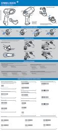
1. Unpacking and Installation1-1. UnpackingAfter unpacking the unit, check that all the necessary accessories are included in the package.1-1-1. U ModelSwitch coverUSB cablePower cordPaper roll holderScrewsRubber feetHolder plateCD-ROMInstallation sheetPrinterRoll paperFig. 1-1 UnpackingIf anything is missing, contact the dealer where you bought the printer and ask them to supplythe missing part. Note that it is a good idea to keep the original box and all the packingmaterials just in case you need to pack the printer up again and send it somewhere at a laterdate.– 1 –
1-1-2. PU ModelPaper roll holderSwitch coverScrewsConnector cover ARubber feetCD-ROMHolder plateInstallation sheetPrinterRoll paper[Options]AC adapter<strong>STAR</strong>, Adapter PS60A-24AUSB cable<strong>STAR</strong>, USB Cable 1.8M TSP1[Recommended cables]PoweredUSB cable (Y cable)PoweredUSB 24V to USB-B & HOSIDEN-MPoweredUSB cable (straight type)PoweredUSB 24V to 1×8– 2 –
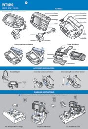
2-1. U Model2. Parts Identification and NomenclaturePrinter coverOpen this cover to load orreplace paper.Cover open leverPush this lever in thedirection of the arrow toopen the printer cover.Power switchUsed to turn on/offpower to the printer.Control panelFeatures LED indicators to indicateprinter status and switches to operatethe printer.USB connectorFor connection to ahost computer using aUSB cable.Peripheral drive connectorConnects to peripheralunits such as cash drawers,etc.Do not connect this to atelephone.Power connectorFor connection of thepower cord.– 3 –
2-2. PU ModelPrinter coverOpen this cover to load orreplace paper.Power switchUsed to turn on/offpower to the printer.Cover open leverPush this lever in thedirection of the arrow toopen the printer cover.Control panelFeatures LED indicators to indicateprinter status and switchesto operate the printer.Power connectorFor connection of the AC adapter orthe PoweredUSB cable (Y cable).USB connectorFor connection to ahost computer usingthe USB cable orPoweredUSB cable(Y cable).PoweredUSB connectorFor connection to a hostcomputer using the PoweredUSBcable (straighttype).Peripheral drive connectorConnects to peripheral units such ascash drawers, etc.Do not connect this to a telephone.– 4 –
2-3. Choosing a place for the printerBefore actually unpacking the printer, you should take a few minutes to think aboutwhere you plan to use it. Remember the following points when doing this.✓ Choose a firm, level surface where the printer will not be exposed to vibration.✓ The power outlet you plan to connect to for power should be nearby and unobstructed.✓ Make sure that the printer is close enough to your host computer for you to connectthe two.✓ Make sure that the printer is not exposed to direct sunlight.✓ Make sure that the printer is well away from heaters and other sources of extremeheat.✓ Make sure that the surrounding area is clean, dry, and free of dust.✓ Make sure that the printer is connected to a reliable power outlet. It should not beon the same electric circuit as copiers, refrigerators, or other appliances that causepower spikes.✓ Make sure that the room where you are using the printer is not too humid.✓ This device employs a DC motor and switches that have an electrical contact point.Avoid using the device in environments where silicon gas can become volatile.WARNING✓ Shut down your equipment immediately if it produces smoke, a strange odor, or unusualnoise. Immediately unplug the equipment and contact your dealer for advice.✓ Never attempt to repair this product yourself. Improper repair work can be dangerous.✓ Never disassemble or modify this product. Tampering with this product may resultin injury, fire, or electric shock.– 5 –
3. Setup3-1. Connecting the USB/PoweredUSB Cable to the Printer3-1-1. U ModelPass the cable through the cable support as shown. Then, connect the USB interface cable tothe printer.– 6 –
3-1-2. PU ModelCAUTIONMake sure that the printer is turned off before connecting the PoweredUSB cable (Y cable) orPoweredUSB cable (straight type).(1) According to the cable used, install the connector cover onto the printer to prevent impropercable connections.USB cable or PoweredUSB cable (Y cable)............Connector cover APoweredUSB cable (straight type)...........................Connector cover BThe printer is shipped with connector cover B installed. This cover does not need to beremoved when using the PoweredUSB cable (straight type). When using a USB cable orPoweredUSB cable (Y cable), remove connector cover (B) and install connector cover (A)to the printer until a click is heard.To remove connector cover (B), use a flat-head screwdriver as shown to push in the hookon the cover.1 Connector cover B23 4Connector cover AHookConnector cover BHook– 7 –
(2) Connect the interface cable to the printer as shown. When using the USB cable, securethe cable with the hook.USB cablePoweredUSB cable (Y cable)PoweredUSB cable (straight type)– 8 –
3-2. Connecting to a Peripheral UnitYou can connect a peripheral unit to the printer using a modular plug. The following describeshow to install the ferrite core and make the actual connection. See “Modular plug” onpage 30 PoweredUSB for details about the type of modular plug that is required. Note thatthis printer does not come with a modular plug or wire, so it is up to you to obtain one thatsuits your needs.CAUTIONMake sure that the printer is turned off and unplugged from the AC outlet and that the computeris turned off before making connections.(1) Connect the peripheral drive cable to the connector on the rear panel of the printer.CAUTIONDo not connect a telephone line into the peripheral drive connector. Failure to observe thismay result in damage to the printer.Also, for safety purposes, do not connect wiring to the external drive connector if there is achance it may carry peripheral voltage.[U Model] [PU Model]– 9 –
3-3. Loading the Roll PaperBe sure to use roll paper that matches the printer’s specification.When using a paper roll with an 57.5 mm width, install the paper roll holder as described onthe following page.Cover open lever1) Push the cover open lever, and open the printercover.2) While observing the direction of the roll, setthe paper roll into the hollow, and pull on theleading edge of the paper toward you.Roll paperPaper roll holderNote: When using a paper roll with an 57.5 mmwidth, install the paper roll holder in thegroove in the printer.If a paper roll with a 57.5 mm widthhas been used, a paper roll with a 79.5mm width cannot be used. (Changingfrom the smaller roll to a larger rollwill cause part of the print head to rubagainst the platen and deteriorate.)3) Push down both sides of the printer cover toclose.Note: Make sure that the printer cover is securelyclosed.Tear Bar Model4) Tear Bar Model:Tear off the paper as shown.Auto Cutter Model:If the printer cover is closed after turning onthe power, the cutter operates automaticallyand the front end of the paper is cut.– 10 –
Caution SymbolThese labels are located near the thermal print head.Because the thermal print head is hot immediately after printing, do nottouch it. Static electricity can damage the thermal print head. To protect thethermal print head from static electricity, do not touch it.This symbol is placed near the cutter.Never touch the cutter blade, as you could injure your fingers.This symbol is placed near the peripheral drive connector.Do not connect this to a telephone.This symbol label or stamp is placed near the screws securing the case orthe protective plate, which should not be opened by individuals other thanservice personnel. Individuals, other than service personnel, should notremove these screws. High voltage areas in the case can be dangerous.Thermal headWARNING1) Do not touch the cutter blade.• There is a cutter inside the paper outlet slot. Not only should you not put your hand inthe paper outlet slot while printing is in progress, never put your hand into the outleteven when printing is not in progress.• The printer cover can be opened when replacing the paper. However, since the cutterblade is on the inside of the printer cover, be careful not to place your face or handstoo close to the cutter blade.2) During and immediately after printing, the area around the thermal head is very hot. Donot touch it, as you could be burned.3) Unplug the equipment immediately if it produces smoke, a strange odor, or unusual noiseand contact your dealer for advice.4) Never attempt to repair this product yourself. Improper repair work can be dangerous.5) Never disassemble or modify this product. Tampering with this product may result ininjury, fire, or electric shock.– 11 –
CAUTION1) Do not operate the cover open lever while pressing on the printer cover with your hand.2) Do not push the cover open lever and open the printer cover when printing is in progressor when the auto cutter is operating.3) Do not push out paper while the printer cover is closed.4) The heating element and the driver IC of the thermal head are easily damaged. Do nottouch them with metal objects, sandpaper, etc.5) Printing quality may suffer if the thermal head heating element becomes soiled by beingtouched with your hands. Do not touch the thermal head heating element.6) There is a risk of damage to the driver IC of the thermal head from static electricity.Never directly touch the IC.7) The printing quality and working life of the thermal head cannot be guaranteed if anypaper other than that recommended is used. In particular, paper containing [Na+, K+,C1-] may drastically reduce the working life of the thermal head. Please exercise caution.8) Do not operate the printer if there is moisture on the front surface of the head from condensation,etc.9) A printed piece of thermal paper may become electrically charged. If the printer isplaced vertically or mounted on a wall, the cut piece of paper may stick to the printer,instead of falling. Beware that this could cause a problem if you use a stacker that storesthe pieces of paper that fall freely.10) Do not change the paper width during use. The thermal printing head, rubber roller, andcutter wear differently according to the paper width. This can cause the printing or cuttermovement to malfunction.11) Do not transport the printer with its cover open and holding it by the cover.12) Do not forcibly pull on the interface cable, power cord, or cash drawer cable that is connected.To detach a connector, make sure to grasp it at the connector portion, withoutapplying excessive stress on the connector at the printer13) If your printer gets hang-up, you must reset it by plugging out/in the USB cable. However,the intervals of per plugging out/in must be 5 seconds or more. Shorter interval maycause malfunction.14) Do not turn off the computer or put the cpmputer in stand-by mode during printing.15) Do not unplug the power cord or disconnect the USB cable during it is working.Notes on Using the Auto Cutter1) If the cutter is not in its home position after an error, first eliminate the cause of the error;then, turn the power back ON.2) A margin of 5 mm or more is recommended from the end of the printed area to the cuttingposition.3) Do not attempt to remove the paper during a cut, as this can cause a paper jam– 12 –
3-4. Connecting the USB/PoweredUSB Cable to the PC3-4-1. U ModelConnect the USB interface cable to a USB port of your PC.3-4-2. PU ModelCAUTIONMake sure that the PC is turned off before connecting the PoweredUSB cable (Y cable) orPoweredUSB cable (straight type).Connecting the USB cableConnecting the PoweredUSB cable (Y cable) orPoweredUSB cable (straight type)Connect the interface cable to a USB port of your PC.– 13 –
3-5. Connecting the Power Cord3-5-1. U ModelNote: Before connecting/disconnecting the power cord, make sure that power to the printerand all the devices connected to the printer is turned off. Also make sure the powercable plug is disconnected from the AC outlet.(1) Check the label on the back or bottom of the printer to make sure its voltage matchesthat of the AC outlet. Also make sure the plug on the power cord matches the AC outlet.(2) If the power cord is not attached to the printer, plug the appropriate end into the AC inleton the back of the printer.(3) Plug the power cord into a properly grounded AC outlet.CAUTIONIf the voltage shown on the label on the bottom of your printer does notmatch the voltage for your area, contact your dealer immediately.– 14 –
3-5-2. PU ModelNote: Before connecting/disconnecting the AC adapter, make sure that power to the printerand all the devices connected to the printer are turned off. Also make sure the powercable plug is disconnected from the AC outlet.(1) Connect the AC adapter to the power cable.Note: Use only the standard AC adapter and power cable.(2) Connect AC adapter to the connector on the printer.(3) Insert the power cable plug into an AC outlet.AC outletCAUTIONWhen disconnecting the cable, take hold of the cable connector to pull itout. Releasing the lock makes it easy to disconnect the connector.Pulling the cable excessively could cause damage to the connector.– 15 –
3-6. Turning Power OnMake sure that the Power cord has been connected as described in 3-6.(1) Turn ON the power switch located on the front of the printer.The POWER lamp on the control panel will light up.Power switchCAUTIONWe recommend that you unplug the printer from the power outlet whenever you do not plan touse it for long periods. Because of this, you should locate the printer so that the power outletit is plugged into is nearby and easy to access.When an Switch cover is affixed to the printer above the power switch, the ON/OFF marks ofthe power switch may be hidden. If this occurs, remove the power cord from the outlet to turnthe printer OFF.– 16 –
(1) Attach the holding plate to the printer. Thentighten the two screws that were supplied tosecure it in place.Flangeless screwsø7 or more2 to 3 mmø4(2) Position the printer over the screws, etc., onthe wall and then slide it downward to set itin place.After setting the printer in place, check thescrews on the wall again to make sure thatthey are able to support the printer’s weight.CAUTION• The printer’s weight is approximately 2.4 kgwhen the largest diameter roll paper is loaded.• Use screws on the wall that have both shearstrength and pulling-out strength to withstanda force of at least 12 kgf (118 N).(3) Push the cover open lever, and open the printercover.(4) Insert the roll paper as shown.4-2. Attaching the Rubber Feet(1) Attach the four rubber feet in the positionsshown in the figure.Ensure that any soiling has been completelywiped off before attaching the rubber feet.– 18 –
(2) Push the cover open lever, and open the printercover.(3) Insert the roll paper as shown.4-3. Switch Cover InstallationIt is not necessary to install the switch cover. Only install it if it is necessary for you. By installingthe switch cover, the following become possible.• Preventing the power switch from being operated by mistake.• Ensuring that other people can not easily operate the power switch.Install the switch cover as shown in the diagram below.The power switch can be turned ON ( | ) and OFF (O) by inserting a narrow instrument (ballpen etc.) in the holes in the switch cover.CAUTIONWe recommend that you unplug the printer from the power outlet whenever you do not plan touse it for long periods. Because of this, you should locate the printer so that the power outletit is plugged into is nearby and easy to access.– 19 –
5. Thermal Roll Paper SpecificationWhen consumable parts have run out, use those specified below.5-1. Roll paper specificationThermal paperThickness: 57~85 µm (excluding Mitsubishi HiTec F5041)Note: When using thin paper with a thickness of less than 65 μm, only the F5041(Mitsubishi HiTec Paper Flensburg GmbH),TF50KS-E2D (Nippon PaperIndustries) and P300/P310 (KSP) paper types are recommended.Width: 79.5±0.5 mm (57.5±0.5 mm when the paper roller holder is used)Outer roll diameter: ø83 mm or less+ 0.5+ 0.5Take up paper roll width: 80 -1 mm or (58 -1 mm when the paper roller holder is used)Core outer/inner diameter: Core outer Core innerø18±1 mm ø12±1 mmPrinted surface: Outer edge of rollTail end handling: Do not use paste or glue to secure the roll paper or its core.Do not fold the tail end of the paper.5-2. Recommended paperNote:1) The print density may vary depending on the type of roll paper, operating environment,and power consumption mode.2) A reader or scanner may not be able to scan a printed bar code or characters dependingon the print density. Make sure that your reader or scanner is able to scan correctly beforehand.5-2-1. U ModelManufacturer Product name Quality characteristics/UsePaper thickness(µm)P220AG normal type paper 65Mitsubishi Paper MillsHP220A high image stability paper 65LimitedHP220AB-1 high image stability paper 75Mitsubishi HiTec PaperFlensburg GmbHF5041 normal type paper 60PD150R normal type paper 75Oji Paper Co., Ltd.PD160R high image stability paper 75PD170R high image stability paper 75PD190R middle image stability paper 75Nippon Paper Industries TF50KS-E2D normal type paper 59P320RB 2 color paper: Red & Black 65Kanzaki Specialty PapersP320BB 2 color paper: Blue & Blac 65Inc. (KSP)P300 / P310 normal type paper 57 / 58Note: The P300/P310 (KSP) paper types cannot be used when the printer is positioned vertically.– 20 –
5-2-2. PU ModelManufacturer Product name Quality characteristics/UsePaper thickness(µm)Power consumptionmodeP220AG normal type paper 65Mitsubishi Paper MillsHP220A high image stability paper 65LimitedHP220AB-1 high image stability paper 75Mitsubishi HiTec PaperFlensburg GmbHF5041 normal type paper 60PD150R normal type paper 75Oji Paper Co., Ltd.PD160R high image stability paper 75PD170R high image stability paper 75PD190R middle image stability paper 75Nippon Paper Industries TF50KS-E2D normal type paper 59P320RB 2 color paper: Red & Black 65 Standard mode onlyKanzaki Specialty PapersP320BB 2 color paper: Blue & Blac 65 Standard mode onlyInc. (KSP)P300 / P310 normal type paper 57 / 58Note: The P300/P310 (KSP) paper types cannot be used when the printer is positioned vertically.Note:Access the following URL for the information of the recommended paper.http://www.star-m.jp/eng/dl/dl02.htm– 21 –
6-1. Control Panel6. Control Panel and Other Functions1 POWER lamp (Green LED)Lights when the power is ON.3 FEED button2 ERROR lamp (Red LED)1 POWER lamp (Green LED)2 ERROR lamp (Red LED)Indicates various errors in combinationwith POWER lamp.3 FEED buttonPress the FEED button to feed roll paper.6-2. Errors1) Automatically recoverable errorsError DescriptionHead high temperaturedetectionBoard high temperaturedetectionCover open errorPOWER LampFlashes at 0.5-secondintervalsFlashes at 2-secondintervalsOnERROR LampOffOffOnRecovery ConditionsAutomatically recovered after theprint head has cooled.Automatically recovered after theboard has cooled.Automatically recovered after theprinter cover is closed.– 22 –
2) Non-recoverable errorsError DescriptionHead thermistor errorBoard thermistor errorVM voltage errorVCC voltage errorEEPROM errorUSB errorCPU errorRAM errorPOWER LampFlashes at 0.5-second intervalsFlashes at 2-second intervalsOffFlashes at 1-second intervalsFlashes at 0.25-secondintervalsFlashes at 5-second intervalsOffOffERROR LampFlashes at 0.5-second intervalsFlashes at 2-second intervalsFlashes at 1-second intervalsFlashes at 1-second intervalsFlashes at 0.25-secondintervalsFlashes at 5-second intervalsOffOnRecovery ConditionsNon-recoverableNon-recoverableNon-recoverableNon-recoverableNon-recoverableNon-recoverableNon-recoverableNon-recoverableNote:1) If a non-recoverable error occurs, turn the power OFF immediately.2) If a non-recoverable error occurs, please consult the dealer for repairs.3) Paper cut errorError DescriptionPaper cut errorPOWER LampOffERROR LampFlashes at0.125-secondintervalsRecovery ConditionsRecovered by turning the power OFF,eliminating the cause of the error such asjammed paper, returning the cutter to itshome position, and turning the power ON(see 7-3).Note:If the cutter does not return to its home position or does not perform the initial movement,it will result in a non-recoverable error.4) Paper detection errorError DescriptionPaper out errorPOWER LampOnERROR LampFlashes at0.5-second intervalsRecovery ConditionsAutomatically recovered by loading a newpaper roll, then closing the printer cover.– 23 –
6-3. Self-PrintingTest PrintingTurn the power ON while holding the FEED button depressed. Test printing is performed.The version number and printer settings are printed. After the printer starts printing, releaseyour hand from the FEED button. After self-printing is completed, the printer will start in thenormal mode.– 24 –
7. Preventing and Clearing Paper Jams7-1. Preventing Paper JamsThe paper should not be touched during ejection and before it is cut. Pressing or pulling thepaper during ejection may cause a paper jam, paper cutting failure or line feed failure.7-2. Removing Paper JamIf a paper jam occurs, clear it as described below.(1) Set the power switch to off to turn off power to the printer.(2) Push the cover open lever, and open the printer cover.If the printer cover will not open on auto cutter models, it means that the auto cutter isnot at the home position. In this case, return the auto cutter to the home position by followingthe instructions provided in section 7-3. Then open the printer cover after the paperjam has been removed.(3) Remove the jammed paper.CAUTIONTake care not to damage the printer when removing the jammed paper.Since it is easy to damage the thermal head in particular, take care not to touch it.(4) Position the roll paper straight and close the printer cover gently.Note 1: Make sure that the paper is positioned straight. If the printer cover is closed withthe paper skewed, a paper jam may result.Note 2: Lock the printer cover by pressing down on the sides. Do not try to close it bypressing down on the center. The cover may not lock properly.(5) Set the power switch to on to turn on power to the printer. Make sure that the ERRORLED is not lit.Note:While the ERROR LED is lit, the printer will not accept any commands such asthe print command, so make sure that the printer cover is locked properly.Caution SymbolThese labels are located near the thermal print head.Because the thermal print head is hot immediately after printing, do not touchit. Static electricity can damage the thermal print head. To protect the thermalprint head from static electricity, do not touch it.This symbol is placed near the cutter.Never touch the cutter blade, as you could injure your fingers.This symbol is placed near the peripheral drive connector.Do not connect this to a telephone.This symbol label or stamp is placed near the screws securing the case or theprotective plate, which should not be opened by individuals other than servicepersonnel. Individuals, other than service personnel, should not remove thesescrews. High voltage areas in the case can be dangerous.– 25 –
7-3. Releasing a Locked Cutter (Auto Cutter Mode only)If the auto cutter locks up, set the power switch to OFF to turn off the printer, and then set thepower switch to ON to turn the printer back on. A typical locked cutter will be restored whenyou restart the printer.If restarting the printer does not release the locked cutter, follow the steps below.WARNINGSince working on the cutter may be dangerous, be sure to turn off the printer first.(1) Set the power switch to OFF to turn off the printer.(2) Remove the front cover to reveal the auto cutter.(3) Remove any jammed paper.Note: Be careful not to damage the printer while removing any jammed paper.Since the thermal print head is particularly sensitive, be sure not to touch it.Front coverAuto cutter– 26 –
(4) Insert a Philips screwdriver into the manual operation hole on the side of the cutter, andturn it in the direction of the arrow shown on the right until the rear cover is opened.(5) Open the printer cover, remove any jammed paper, and then reinstall the paper roll.(6) Install the front cover, and then set the power switch to ON.– 27 –
8. Periodical CleaningPrinted characters may become partially unclear due to accumulated paper dust and dirt. Toprevent such a problem, paper dust collected in the paper holder and paper transport sectionand on the surface of the thermal head must be removed periodically. Such cleaning is recommendedto be carried out once six month or one million lines.8-1. Cleaning the Thermal HeadTo remove blackish dust collected on the surface of the thermal head, wipe it with Isopropylalcohol (IPA).Note: The thermal head is easy to damage, so clean it gently with a soft cloth. Take sufficientcare not to scratch it when cleaning it.8-2. Cleaning the Paper HolderUse a soft cloth to remove paper dust from the paper holder and paper transport section.Thermal headPaper holder– 28 –
9. Peripheral Unit Drive CircuitPeripheral unit drive circuit connector only connects to peripheral units such as cash drawers, etc.Do not connect it to a telephone.Use cables which meet the following specifications.Peripheral Drive ConnectorPin No.SignalI/OFunctionnamedirection1 FG Frame ground —2 DRD1 Drive signal 1 OUT3 +24V Drive power OUT4 +24V Drive power OUT5 DRD2 Drive signal 2 OUT6 DRSNS Sense signal INModular plugModular plug: MOLEX 90075-0007,AMP641337, or BURNDY B-66-41 6ShieldWire leadDrive circuitThe recommended drive unit is shown below.F.G12With shield6 16-P Modular jackconnectorTR1+24VM-GNDTR2M-GND+5VR1TR3R27824D1D23456L1L2Peripheralunit 2FramegroundPeripheralunit 1R34.7kΩ1/4WCompulsionswitchReference2SD 1866 Circuit ConfigurationBCPrinter sideUser sideDrive Output: 24V, Max. 1.0ATR1, TR2: Transistor 2SD1866 or equivalentR1=10 kΩR2=33 kΩR3R4R3= 3.5kΩR4= 300ΩE– 29 –
Notes: 1. Pin 1 must be shield drain wire connected to peripheral device frame ground.2. It is not possible to drive two drives simultaneously.3. The peripheral drive duty must satisfy the following:ON time / (ON time + OFF time) 0.24. Minimum resistance for coils L1 and L2 is 24Ω.5. Absolute maximum ratings for diodes D1 and D2 (Ta = 25°C) are:Average Rectified Current Io = 1A6. Absolute maximum rating for transistors TR1 and TR2 (Ta = 25°C) are:Collector current Ic = 2A– 30 –
10. Specifications10-1. General Specifications(1) Printing method Direct line thermal printing(2) Print speed Max. 1000 dots/sec. (125 mm/sec.)(3) Dot density 203 dpi: 8 dots/mm (0.125 mm/dot)(4) Printing width Max. 72 mm(5) Roll paper Refer to chapter 5 for details on the recommended roll paper.Paper width:79.5±0.5 mm (57.5±0.5 mm when the paper rollholder is used)Roll diameter: ø83 mm or less(6) Overall dimension 142 (W) × 204 (D) × 132 (H) mm(7) Weight Auto cutter model : 1.72 kg (without roll paper)Tear bar model : 1.56 kg (without roll paper)(8) Noise Approx. U Model49 dB (Auto cutter model)48 dB (Tear bar model)PU Model50 dB (Auto cutter model)50 dB (Tear bar model)Note: The noise measurements listed above were obtained accordingto conditions established by this company. Thenoise measurements may vary depending on the typeof paper used, type of printing, operating environment,and power consumption mode.– 31 –
10-2. Auto Cutter Specifications(1) Cutting frequency Max. 20 cuts per minute(2) Thickness of paper 65~85 µm10-3. Interface(1) Specifications USB 2.0 full speedPrinter class and vendor class compatible(2) ConnectorU ModelType BPU MoedlType B and PoweredUSB connectorType B connector:DUSB-BRA42-T11(D2)-FA (manufacturer: DDK)Pin No. Signal name Function1 VBUS USB Power pin (+5V DC)2 D - Serial Date -3 D + Serial Date +4 GND Signal ground2 13 4PoweredUSB connector:69913-104LF (manufacturer: FCI)Pin No. Signal name Function1 F-GND Frame ground2 +24V +24V DC3 GND Signal ground4 D + Serial Date +5 D - Serial Date -6 VBUS USB Power pin (+5V DC)7 +24V +24V DC8 F-GND Frame ground8110-4. Electrical Characteristics10-4-1. U Model(1) Input Voltage 100 to 240 V AC, 50/60 Hz(2) Current Consumption Operating: Approx. 40 W (at ASCII printing)Stand-by: Approx. 3 W– 32 –
10-4-2. PU Model (AC adapter)(1) Input: 100 to 240V AC, 50/60 Hz(2) Output: DC 24V ± 5%(3) Current Consumption (DC 24 V at room temperature)Low-power consumption mode:Stand-by: Approx. 0.1AMean: Approx. 1.0A (at ASCII continuous printing)Peak: Approx. 5.0A(at print duty 100%, for 10 seconds or less)Standard mode:Stand-by: Approx. 0.1AMean: Approx. 1.4A (at ASCII continuous printing)Peak: Approx. 10.0A(at print duty 100%, for 10 seconds or less)To switch between the standard and low-power consumption modes, refer to chapter 11for details on the DIP switch settings.Notes: There is a danger that there will be a large incoming current when turning theprinter back on after turning it off. Therefore, wait at least 5 seconds before turningthe printer back on.Pin No. Function1 Drive power (24V)2 Signal GND3 N.C.Shell Frame ground132(4) Power ConnectorNotes:• When using a printer power supply other than the optional AC adapter (PS60A-24Aseries), be sure that the following cautions are observed.• Use a power supply of DC 24 V ± 5% and more than 2.0 A (5.0 A Load 10 sec. Min.)with SELV output and LPS or Class 2 output approved by IEC60950.• Be careful about installing the printer in an area where there is noise. Take the appropriatemeasures to protect against electrostatic AC line noise, etc.– 33 –
10-4-3. PU Model (PoweredUSB cable)When using the PoweredUSB cable, DC 24 V must be supplied to the printer from the system.Use a power supply for the printer that meets the following requirements.Power Requirements(1) Output: DC 24V ± 5%(2) Current Consumption (DC 24 V at room temperature)Low-power consumption mode:Stand-by: Approx. 0.1AMean: Approx. 1.0A (at ASCII continuous printing)Peak: Approx. 5.0A(at print duty 100%, for 10 seconds or less)Standard mode:Stand-by: Approx. 0.1AMean: Approx. 1.4A (at ASCII continuous printing)Peak: Approx. 10.0A(at print duty 100%, for 10 seconds or less)To switch between the standard and low-power consumption modes, refer to chapter 11for details on the DIP switch settings.Notes: There is a danger that there will be a large incoming current when turning theprinter back on after turning it off. Therefore, wait at least 5 seconds before turningthe printer back on.– 34 –
10-5. Environmental Requirements(1) OperatingTemperature 5°C to 45°CHumidity10% to 90% RH (without condensation)(%RH)9080Relative humidity60402010Operating environmentrange0 10 2030 40 50Operating temperature and humidity range(2) Transport/storage (except for paper)Temperature -20°C to 60°CHumidity10% to 90% RH (without condensation)– 35 –
10-6. Reliability1) Life Mechanical: 20 million linesHead:100 million pulses, 100 km (±15% max. average head resistancefluctuation)For 2-color printing, 50 million pulses, 50 km (±15% max. averagehead resistance fluctuation)Auto cutter: 1 million cuttings (provided the paper thickness is between 65and 85 µm)Average printing ratio: 12.5%Recommended thermal paper: 65 µm2) MCBF: 60 million linesThe Mean Cycle Between Failure (MCBF) is defined to be the overall failure cycle,which includes random or wear failures that occur until the printer reaches its mechanicallife of 20 million lines.* As the mechanical remains at 20 million lines, the MCBF of 60 million lines does not indicateits useful life.3) Auto Cutter (Life)1 million cuttings (provided the paper thickness is between 65 and 85 µm)* All the reliability values indicated above are based on the use of the recommended thermalpaper. No reliability can be guaranteed for the use of non-recommended thermal paper.– 36 –
11. DIP Switch SettingsThere are DIP switches located on the bottom of the PU model printers and various settingscan be performed as shown in the following table.When changing the settings, use the following procedure.Note: For U model printers, the DIP switch settings do not need to be performed.(1) Turn the printer off and disconnect the power cable plug from the AC outlet.(2) Remove the screw, and then remove the DIP switch cover on the bottom of the printer.[PU model]DIP switch 11 2 3 4OFFONWhen the printer is shipped, DIP switch 1-4 is set toOFF; all of the other switches are set to ON.(3) Use a tool with a narrow tip to change the DIP switch settings.(4) Install the DIP switch cover and secure it with the screw.Note: The new settings will take effect after the printer is turned on.DIP switch 1Switch 1-1OFFONPower consumption modeStandard modeLow-power consumption mode (Default setting)Always set DIP switches 1-2 and 1-3 to ON and DIP switch 1-4 to OFF.– 37 –
SPECIAL PRODUCTS DIVISION<strong>STAR</strong> MICRONICS CO., <strong>LTD</strong>.536 Nanatsushinya, Shimizu-ku, Shizuoka,424-0066 JapanTel: (int+81)-54-347-0112, Fax: (int+81)-54-347-0409Please access the following URLhttp://www.star-m.jp/eng/dl/dl02.htmfor the latest revision of the manual.OVERSEAS SUBSIDIARY COMPANIES<strong>STAR</strong> MICRONICS AMERICA, INC.1150 King Georges Post Road, Edison, NJ 08837-3729 U.S.A.Tel: (int+1)-732-623-5555, Fax: (int+1)-732-623-5590<strong>STAR</strong> MICRONICS EUROPE <strong>LTD</strong>.Star House, Peregrine Business Park, Gomm Road,High Wycombe, Bucks, HP13 7DL, U.K.Tel: (int+44)-1494-471111, Fax: (int+44)-1494-473333


![MC9190-G Quick Start Guide [Spanish] (P/N 72-139206-01ES Rev. A)](https://img.yumpu.com/50178248/1/178x260/mc9190-g-quick-start-guide-spanish-p-n-72-139206-01es-rev-a.jpg?quality=85)