air - Ferroli
air - Ferroli
air - Ferroli
- No tags were found...

You also want an ePaper? Increase the reach of your titles
YUMPU automatically turns print PDFs into web optimized ePapers that Google loves.
HXPAIR - WATERHEAT PUMPSFOR OUTDOOR AND INDOOR INSTALLATIONR410ATECHNICAL MANUAL
TABLE OF CONTENTSGENERAL FEATURES . . . . . . . . . . . . . . . . . . . . . . . . . . . . . . . . . . . . . . . . . . . . . . . . . . . . . . . . . . . . . . . . . . . . . . . . . . . . . . .5UNIT DESCRIPTION . . . . . . . . . . . . . . . . . . . . . . . . . . . . . . . . . . . . . . . . . . . . . . . . . . . . . . . . . . . . . . . . . . . . . . . . . . . . . .5UNIT IDENTIFICATION CODE . . . . . . . . . . . . . . . . . . . . . . . . . . . . . . . . . . . . . . . . . . . . . . . . . . . . . . . . . . . . . . . . . . . . . .5DESCRIPTION OF COMPONENTS . . . . . . . . . . . . . . . . . . . . . . . . . . . . . . . . . . . . . . . . . . . . . . . . . . . . . . . . . . . . . . . . . .6CONTROL SYSTEM . . . . . . . . . . . . . . . . . . . . . . . . . . . . . . . . . . . . . . . . . . . . . . . . . . . . . . . . . . . . . . . . . . . . . . . . . . . . . .7OPTIONS . . . . . . . . . . . . . . . . . . . . . . . . . . . . . . . . . . . . . . . . . . . . . . . . . . . . . . . . . . . . . . . . . . . . . . . . . . . . . . . . . . . . . . .8ACCESSORIES . . . . . . . . . . . . . . . . . . . . . . . . . . . . . . . . . . . . . . . . . . . . . . . . . . . . . . . . . . . . . . . . . . . . . . . . . . . . . . . . . .9TECHNICAL DATA AND PERFORMANCES . . . . . . . . . . . . . . . . . . . . . . . . . . . . . . . . . . . . . . . . . . . . . . . . . . . . . . . . . . . . .10TECHNICAL DATA . . . . . . . . . . . . . . . . . . . . . . . . . . . . . . . . . . . . . . . . . . . . . . . . . . . . . . . . . . . . . . . . . . . . . . . . . . . . . . .10NOMINAL PERFORMANCES - LOW TEMPERATURE PLANTS . . . . . . . . . . . . . . . . . . . . . . . . . . . . . . . . . . . . . . . . . . .11NOMINAL PERFORMANCES - MEDIUM TEMPERATURE PLANTS . . . . . . . . . . . . . . . . . . . . . . . . . . . . . . . . . . . . . . . .11HEATING PERFORMANCES . . . . . . . . . . . . . . . . . . . . . . . . . . . . . . . . . . . . . . . . . . . . . . . . . . . . . . . . . . . . . . . . . . . . . .12COOLING PERFORMANCES . . . . . . . . . . . . . . . . . . . . . . . . . . . . . . . . . . . . . . . . . . . . . . . . . . . . . . . . . . . . . . . . . . . . . .13PLANT SIDE HYDRAULIC PERFORMANCES . . . . . . . . . . . . . . . . . . . . . . . . . . . . . . . . . . . . . . . . . . . . . . . . . . . . . . . . .14PLANT SIDE AERAULIC PERFORMANCES . . . . . . . . . . . . . . . . . . . . . . . . . . . . . . . . . . . . . . . . . . . . . . . . . . . . . . . . . .17OPERATING LIMITS . . . . . . . . . . . . . . . . . . . . . . . . . . . . . . . . . . . . . . . . . . . . . . . . . . . . . . . . . . . . . . . . . . . . . . . . . . . . .18ELECTRICAL DATA . . . . . . . . . . . . . . . . . . . . . . . . . . . . . . . . . . . . . . . . . . . . . . . . . . . . . . . . . . . . . . . . . . . . . . . . . . . . . .19NOISE LEVELS . . . . . . . . . . . . . . . . . . . . . . . . . . . . . . . . . . . . . . . . . . . . . . . . . . . . . . . . . . . . . . . . . . . . . . . . . . . . . . . . .20WEIGHTS . . . . . . . . . . . . . . . . . . . . . . . . . . . . . . . . . . . . . . . . . . . . . . . . . . . . . . . . . . . . . . . . . . . . . . . . . . . . . . . . . . . . .21OVERALL DIMENSIONS . . . . . . . . . . . . . . . . . . . . . . . . . . . . . . . . . . . . . . . . . . . . . . . . . . . . . . . . . . . . . . . . . . . . . . . . . .22MINIMUM OPERATING AREA . . . . . . . . . . . . . . . . . . . . . . . . . . . . . . . . . . . . . . . . . . . . . . . . . . . . . . . . . . . . . . . . . . . . .223
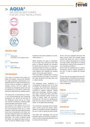
GENERAL FEATURESUnit descriptionThis series of <strong>air</strong>-water heat pumps satisfies the heating,cooling and domestic hot water production requirements ofresidential plants of small and medium size.All the units are suitable for outdoor or indoor installation andcan be applied to fan coil plants, radiant floor plants and highefficiency radiators plants.The control system allows to manage not only the refrigerantcircuit but the whole plant with the possibility to choose differentsolutions both for the heating and cooling plant and for thedomestic hot water management. The possibility of solarpanels or other heating sources integration is also available.The heating function optimizes the flow water temperatureaccording both to the ambient temperature and to the outdoortemperature through climatic curves adaptable to the buildingfeatures. It’s possible to manage a storage tank and two independentcircuits (a direct one and a mixed one).The domestic hot water management allows to control thethree way valve, the storage tank and the anti-legionellacycles (if necessary).The cooling function can be realized through “active cooling”(refrigerant circuit inversion). When the unit is used in radiantfloor plants, to avoid condensate generation, a room humiditysensor can be installed.The internal programmer clock allows to define differentdaily switching programs for heating, cooling and domestic hotwater production.The refrigerant circuit, contained in a box rep<strong>air</strong>ed from the <strong>air</strong>flow to simplify the maintenance operations, is equipped withscroll compressor mounted on damper supports, brazed plateheat exchanger, electronic expansion valve, reverse cyclevalve centrifugal fan (plug fan), finned coil realized with copperpipes and alluminium fins. The circuit is protected by highand low pressure switches and flow switch on the plate heatexchanger.The plate heat exchanger and all the hydraulic pipes are thermallyinsulated in order to avoid condensate generation andreduce thermal losses.The plug fan with electronic control of the rotational speedguarantees high efficiencies and low noise in all the operatingconditions and allows to install the unit both outdoor (with protectioncaps) or indoor (with ducted <strong>air</strong> inlet and outlet).All three-phase power supply units are provided with a phasesequence and correct sequence controller device.All the units are accurately built and individually tested in thefactory. Only electric and hydraulic connections are requiredfor installation.Unit identification codeThe codes that identify the units and the meaning of the letters used are described below.HXP IP 16.1 VB AB 0 M 1Unit typeIP - Units suitable forhydronic plant installationoperating as reversible heatpumpsUnit versionVB - Base VersionUnit modelN° compressorsAcoustic setting upAB - Base setting upPower supply1 - 230V - 1 - 50 Hz5 - 400V - 3N - 50 HzOperating rangeM - Medium temperature.The unit is suitable to producewater at medium temperatureRefrigerant type0 - R410A5
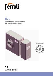
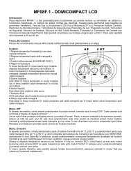
GENERAL FEATURESDescription of componentsExternal structure. Basement, supporting structure and lateralpanels are made of galvanized and painted sheet-steel toguarantee good resistance to atmospheric agents.Accessibility to internal parts is possible removing the lateralpanels. For extraordinary manteinances also the other panelscan be removed.re residuals that could be present in the circuit, high and lowpressure switches in order to assure the compressor to operateinside the permitted limits, 4 way reverse cycle valve (6)to allow operating mode change reversing the refrigerant flow,liquid receiver (7) to compensate the different refrigerantcharge required in heating and in cooling mode and pressureconnections SAE 5/16” - UNF 1/2” - 20 equipped with pin,gasket and blind nut, as required for the use of R410A refrigerant(they allow the complete check of the refrigerant circuit:compressor inlet pressure, compressor outlet pressure andexpansion valve upstream pressure). All the pipes of the refrigerantcircuit are properly insulated to avoid condensategeneration and minimize thermal lossesThe plug fan (8) is equipped with an high efficiency electronicallycommutated (EC) motor and guarantees enough availablestatic pressure to allow both the outdoor and the indoorinstallation.Hydraulic circuit. All the pipes are thermally insulated toavoid condensate generation and minimize thermal losses.The circuit can be equipped with a standard or a high head circulationpump (option). The circuit is always equipped alsowith expansion vessel and <strong>air</strong> vents.Refrigerant circuit. It is contained inside a compartmentseparated from the <strong>air</strong> flow to simplify maintenance and controloperations.The hermetic scroll compressor (1) is mounted on dampersupports and is protected against overtemperatures and overcurrents.It is equipped with an electrcal heater, that is activatedwhen the compressor turns off, to keep the compressorcrankcase oil temperature high enough to prevent migration ofthe refrigerant during winter stops and to evaporate any liquidpresent in the crankcase, in order to prevent possible liquidrushes on starting.The plant side heat exchanger (2) is a brazed stainless steelplate heat exchanger, properly insulated to avoid condensategeneration and to minimize thermal losses, and protected bya flow switch that detects whatever water flow lack.The source side heat exchanger (3) is a finned coil realizedwith grooved copper pipes and hydrophilic aluminium fins withwaved profile to increase the heat exchange coefficient. A trayis placed under the coil to collect the condensate generated inheating mode.Electrical panel. It contains all the power, control and securitycomponents necessary to guarantee the unit to work properly.The unit is managed by a microprocessor controller towhich all the electrical loads and the control devices are connected.The user interface, to be placed indoor, allows to viewand to modify, if necessary, all the parameters of the unit.All the units are supplied with an outdoor temperature sensor,to be installed outside, in order to realize the climatic control.8364The expansion device (4), an electronic expansion valve,allows the unit to adjust itself to the different operating conditionskeeping steady the set superheating.7The refrigerant circuit of each unit contains moreover solidcore hermetic filter dryer (5) to restrain impurity and moistu-2156
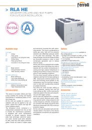
GENERAL FEATURESControl systemThe microprocessor controller is able to manage not only theunit itself but also all that components of the plant which allowto realize a complete system.The main functions of the control system are :- room temperature control according to the outdoor temperature(climatic control)- domestic hot water production (management of 3 wayvalve, storage tank, anti legionella cycles…)- management of a heating and/or cooling mixed circuit(pump and 3 way mixing valve)- management of a heating direct circuit (only pump)- management of a storage tank for heating and/or cooling- management of electrical heaters for heating and domestichot water (3 steps logic)- solar panels integration- room humidity control for cooling with radiant systems- internal programmer clock (for heating, cooling and domestichot water)- digital input for electrical energy low tariff- alarm memory management and diagnostic- compressor and pump operating hour counter- possibility to manage more units in cascade (maximum 16)Besides the user interface of the unit to be placed indoor,wired or wireless remote thermostats are available whichallow to control allthe operating parametersof the unitand to acquire thetemperature in thedifferent zones inorder to realize amore precise andcomfortable control.18:2820.5 CRoom temperatureThe unit controlleris able to managea lot of differentplant solutionsenabling automaticallythe necessarycontrol algorythmsaccording to thecomponents whichhave been connected.The managementof such components is possible through additionalexpansion modules which communicate with the unit bymeans of an internal bus and provide all the inputs and outputsrequired to fulfil a complete system.FSThe controller is able to manage up to two zones in heating(one by means of a mixed circuit and the other by means of adirect circuit) and one zone in cooling (by means of a mixedcircuit).It’s possible to realize more complex plants connecting to theheat pump controller further expansion modules in order toextend without limits the number of zones to be managed.For each zone the following parameters can be set :- set point- daily or weekly operating time table- climatic control curve- room control sensor : it can be in common with the otherzones or independent (in that case it’s necessary to installan additional room thermostat)7
GENERAL FEATURESOptionsPlant sideflow ratemanagementDomestic hot waterproductionIntegrative electrical heatersStandard pumpHigh head pumpHigh efficiency pump3 way valveAllows the circulation of the water on the plant side.Allows the circulation of the water on the plant side and guarantees a higheravailable static head.Allows the circulation of the water on the plant side and guarantees a highefficiency.Allow to divert the hot water produced by the heat pump from the heating circuitto the domestic hot water circuit.Integrate or replace the heating power supplied by the heat pump and aremanaged by the unit controller with a 3 step logic.Soft starterReduces the compressor start current.The controller flexibility and the big number of optionsavailable allow to get, for each model, a lot of differentconfigurations that integrate inside the heatpump many components of the plant and allow torealize compact and tested installations.In order to select the right configuration it is necessaryto define the type of plant to which the heatpump will be connected, both for what concerning theheating and cooling circuits, and for what concerningthe domestic hot water management.Reversible heat pump (IP) without optionsOption “Plant side flow rate management”Option “Integrative electrical heaters”Pump (standard or high head or high efficiency)8
GENERAL FEATURESOption “Domestic hot water production”3 way valveIn this configuration the heat pumpcan be coupled to a domestic hotwater tank equipped with a coil designedfor a maximum water temperaturebetween 55°C and 60°C.The anti legionella cycles have to beperformed by means of electricalheaters placed on the heat pumpoutlet (see option “Integrative electricalheaters”) or directly inside thetank.AccessoriesRubber vibration dampersAdjustable rubbervibration dampersAllow to reduce the transmission to the unit support plane of the mechanical vibrations generated by the compressorand by the fans in their normal operating mode.Allow to reduce the transmission to the unit support plane of the mechanical vibrations generated by the compressorand by the fans in their normal operating mode. Their height can be adjusted to fit to the ground unevenness.Protection capsRemote thermostatRemote control(wired or wireless)Wireless transmitterWireless repeaterProtect the external surface of the finned coil and the fan and reduce the noise emitted by the unit.Allows operating mode selection and set point adjustment. The on board temperature sensor can be used inorder to realize a climatic control.Replicates all the control and visualization functionalities of the controller installed on the unit. The on boardtemperature sensor can be used in order to realize a climatic control.Connected to the unit controller, allows to communicate with wireless remote control and wireless outdoortemperature sensor.Extends wireless operating range.Wireless adaptor for outdoortemperature sensorAllows to transform the wired outdoor temperature sensor, standard for all the units, in a wireless sensor.Condensate sensorIn cooling mode it allows the minimum flow temperature control when condensate generation occurs.Room hygrostatRoom humidity sensor(with or without display)Transformer230V / 24V - 3VAIn cooling mode it allows the minimum flow temperature control according to the room humidity.In cooling mode it allows the minimum flow temperature control according to the room dew point, calculatedfrom the measured room humidity.It assures the correct power supply for the condensate sensor and for the room humidity sensor.9
TECHNICAL DATA AND PERFORMANCESTechnical dataFrame 1 2 3Model 11.1 13.1 16.1 18.1 21.1 24.1 27.1 31.1 35.1 U.M.Power supply230 -1- 50400 -3N- 50230 -1- 50400 -3N- 50400 -3N- 50 400 -3N- 50 400 -3N- 50 400 -3N- 50 400 -3N- 50 400 -3N- 50 400 -3N- 50 V-ph-HzRefrigeranType R410A -CompressorType scroll -Quantity 1 n°Power steps 0 - 100 %Oil charge 1,2 1,8 1,8 1,8 1,8 2,5 3,3 3,3 3,3 kgPlant side heat exchangerType stainless steel brazed plates -Quantity 1 n°Water volume 1,04 1,04 1,04 3,33 3,33 3,33 4,18 4,18 4,18 lSource side heat exchangerType finned coil -Quantity 1 n°Frontal surface 0,55 0,55 0,55 0,77 0,77 0,77 1,10 1,10 1,10 m 2FansType plug fan with high efficiency EC motor -Quantity 1 n°Diameter 500 500 500 630 630 630 630 630 630 mmMaximum rotational speed 750 750 750 680 680 680 680 680 680 rpmToatal installed power 0,26 0,26 0,26 0,54 0,54 0,54 0,54 0,54 0,54 kWPlant side hydraulic circuitExpansion vessel volume 10 lPlant pump - standard (option)Type 3 speed glandless pump -Quantity 1 n°Installed power 0,15 0,15 0,15 0,21 0,21 0,21 0,41 0,41 0,41 kWPlant pump - high head (option)Type 3 speed glandless pump -Quantity 1 n°Installed power 0,21 0,21 0,21 0,41 0,41 0,41 0,45 0,45 0,45 kWPlant pump - high efficiency (option)Type inverter glandless pump -Quantity 1 n°Installed power 0,14 0,14 0,14 0,14 0,14 0,14 0,31 0,31 0,31 kWIntegrative electrical heaters (option)Total installed power 9,0 9,0 9,0 9,0 9,0 9,0 18,0 18,0 18,0 kWPower steps 0 - 33 - 66 - 100 %10
TECHNICAL DATA AND PERFORMANCESNOMINAL performances - low temperature plantsFrame 1 2 3Model 11.1 13.1 16.1 18.1 21.1 24.1 27.1 31.1 35.1 U.M.Power supply230 -1- 50400 -3N- 50230 -1- 50400 -3N- 50400 -3N- 50 400 -3N- 50 400 -3N- 50 400 -3N- 50 400 -3N- 50 400 -3N- 50 400 -3N- 50 V-ph-HzIPHeating A7W35 ( source : <strong>air</strong> in 7°C d.b. 6°C w.b. / plant : water in 30°C out 35°C )Heating capacity 11,1 12,8 15,3 18,1 21,0 23,5 26,9 30,7 34,3 kWPower input 2,64 3,07 3,68 4,14 4,81 5,18 5,80 6,79 7,75 kWCOP 4,20 4,17 4,16 4,37 4,37 4,54 4,64 4,52 4,43 -Water flow rate plant side 1903 2194 2606 3103 3583 4011 4594 5246 5846 l/hPressure drops plant side 14 18 23 13 17 21 18 23 28 kPaHeating A2W35 ( source : <strong>air</strong> in 2°C d.b. 1°C w.b. / plant : water in 30°C out 35°C )Heating capacity 9,23 10,6 12,6 15,0 17,3 19,4 22,2 25,5 28,4 kWPower input 2,61 3,02 3,61 4,08 4,73 5,10 5,71 6,67 7,61 kWCOP 3,54 3,51 3,49 3,68 3,66 3,80 3,89 3,82 3,73 -Water flow rate plant side 1579 1817 2160 2571 2966 3326 3806 4354 4851 l/hPressure drops plant side 10 13 17 9 12 15 12 16 19 kPaCooling A35W18 ( source : <strong>air</strong> in 35°C d.b. / plant : water in 23°C out 18°C )Cooling capacity 11,7 13,5 15,9 19,1 21,9 24,6 28,1 32,1 35,7 kWPower input 3,71 4,30 5,15 5,80 6,74 7,25 8,14 9,50 10,9 kWEER 3,15 3,14 3,09 3,29 3,25 3,39 3,45 3,38 3,28 -Water flow rate plant side 2009 2318 2748 3280 3778 4242 4843 5530 6165 l/hPressure drops plant side 15 19 25 14 19 23 19 25 31 kPaNOMINAL performances - medium temperature plantsFrame 1 2 3Model 11.1 13.1 16.1 18.1 21.1 24.1 27.1 31.1 35.1 U.M.Power supply230 -1- 50400 -3N- 50230 -1- 50400 -3N- 50400 -3N- 50 400 -3N- 50 400 -3N- 50 400 -3N- 50 400 -3N- 50 400 -3N- 50 400 -3N- 50 V-ph-HzIPHeating A7W45 ( source : <strong>air</strong> in 7°C d.b. 6°C w.b. / plant : water in 40°C out 45°C )Heating capacity 10,9 12,5 15,0 17,7 20,6 23,0 26,4 30,1 33,5 kWPower input 3,22 3,73 4,47 5,03 5,85 6,29 7,06 8,25 9,41 kWCOP 3,39 3,35 3,36 3,52 3,52 3,66 3,74 3,65 3,56 -Water flow rate plant side 1861 2134 2544 3022 3500 3910 4490 5122 5703 l/hPressure drops plant side 13 17 22 12 16 20 17 21 26 kPaHeating A2W45 ( source : <strong>air</strong> in 2°C d.b. 1°C w.b. / plant : water in 40°C out 45°C )Heating capacity 9,00 10,4 12,3 14,7 16,9 19,0 21,7 24,9 27,7 kWPower input 3,18 3,69 4,41 4,98 5,78 6,21 6,97 8,14 9,28 kWCOP 2,83 2,82 2,79 2,95 2,92 3,06 3,11 3,06 2,98 -Water flow rate plant side 1535 1776 2100 2510 2885 3244 3705 4234 4712 l/hPressure drops plant side 10 12 16 9 11 14 12 15 18 kPaCooling A35W7 ( source : <strong>air</strong> in 35°C d.b. / plant : water in 12°C out 7°C )Cooling capacity 8,98 10,4 12,3 14,7 16,9 19,0 21,7 24,7 27,5 kWPower input 3,42 3,96 4,74 5,35 6,21 6,67 7,49 8,74 9,96 kWEER 2,63 2,63 2,59 2,75 2,72 2,85 2,90 2,83 2,76 -Water flow rate plant side 1543 1785 2111 2522 2900 3260 3724 4255 4736 l/hPressure drops plant side 10 13 17 9 11 14 12 15 19 kPaData declared according to EN 14511. The values are referred to units without options or accessories.11
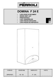
TECHNICAL DATA AND PERFORMANCESHEATING performancesHeating capacity1,51,4The graphs allow to get the corrective factors to beapplied to the nominal performances in order toobtain the real performances in the selected operatingconditions.1,31,21,1BAThe reference nominal condition is :A7W35source : <strong>air</strong> in 7°C d.b. 6°C w.b.plant : water in 30°C out 35°CC1,00,9DOutlet temperatureplant side :0,8A = 55°CB = 45°C0,7C = 35°C0,6D = 25°C0,5-20 -15 -10 -5 0 5 10 15 20Inlet <strong>air</strong> temperature w.b. [°C]Power inputCOP1,52,01,41,31,8D1,6C1,2B1,11,4A1,01,20,91,00,80,80,70,6ABCD0,60,5-20 -15 -10 -5 0 5 10 15 200,4-20 -15 -10 -5 0 5 10 15 20Inlet <strong>air</strong> temperature w.b. [°C]Inlet <strong>air</strong> temperature w.b. [°C]12
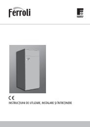
TECHNICAL DATA AND PERFORMANCESCOOLING performancesCooling capacity1,51,4The graphs allow to get the corrective factors to beapplied to the nominal performances in order toobtain the real performances in the selected operatingconditions.1,31,21,1The reference nominal condition is :A35W7source : <strong>air</strong> in 35°C d.b.plant : water in 12°C out 7°C1,00,9Outlet temperatureplant side :0,8A = 24°CB = 18°C0,7C = 12°C0,6ABCDD = 7°C0,515 20 25 30 35 40 45 50Inlet <strong>air</strong> temperature d.b. [°C]Power inputEER1,52,01,41,8A1,3B1,6C1,2BD1,1A1,41,0D1,20,9C1,00,80,70,80,60,60,515 20 25 30 35 40 45 500,415 20 25 30 35 40 45 50Inlet <strong>air</strong> temperature d.b. [°C]Inlet <strong>air</strong> temperature d.b. [°C]13
TECHNICAL DATA AND PERFORMANCESPlant side hydraulic performancesPressure drops - unit without options605024.1Pressure drops [ kPa ]40302011.113.116.118.121.135.11027.131.100 1000 2000 3000 4000 5000 6000 7000Flow rate [ l/h ]Pressure drops to be added - unit with option “Integrative electrical heaters”605016.1Pressure drops [ kPa ]4030201011.118.113.121.124.127.131.135.100 1000 2000 3000 4000 5000 6000 7000Flow rate [ l/h ]The graphs are referred to units operating with water at the temperature of 10°C (density 1000 kg/m 3 ).14
TECHNICAL DATA AND PERFORMANCESAvailable static head - unit with option “Plant side flow rate management” : “Standard pump”180160Available static head [ kPa ]140120100806018.121.124.127.131.135.1402011.113.116.100 1000 2000 3000 4000 5000 6000 7000Flow rate [ l/h ]Available static head - unit with option “Plant side flow rate management” : “High head pump”180Available static head [ kPa ]1601401201008060402011.113.116.118.121.124.127.131.135.100 1000 2000 3000 4000 5000 6000 7000Flow rate [ l/h ]The graphs are referred to units operating with water at the temperature of 10°C (density 1000 kg/m 3 ).15
TECHNICAL DATA AND PERFORMANCESAvailable static head - unit with option “Plant side flow rate management” : “High efficiency pump”180Available static head [ kPa ]160140120100806018.121.124.127.131.135.1402011.113.116.100 1000 2000 3000 4000 5000 6000 7000Flow rate [ l/h ]The graphs are referred to units operating with water at the temperature of 10°C (density 1000 kg/m 3 ).16
TECHNICAL DATA AND PERFORMANCESPlant side aeraulic performancesAvailable static head - unit without accessory “Protection caps”9080Available static head [ kPa ]706050403011.113.116.118.121.127.131.135.1201024.100 1000 2000 3000 4000 5000 6000 7000 8000 9000 10000Flow rate [ m 3 /h ]Frame 1 2 3Model 11.1 13.1 16.1 18.1 21.1 24.1 27.1 31.1 35.1 U.M.Maximum static headavailable for ducted installation30 30 30 50 50 50 50 50 50 PaIn case of ducted installation the total pressure drops in the inlet and outlet ducts can not exceed the maximum available static head.The minimum duct section must guarantee that the medium <strong>air</strong> velocity does not exceed 2,5 m/s in order to avoid noise problemsand to keep the pressure drops as lower as possible.The graphs are referred to units operating with <strong>air</strong> at the temperature of 15°C (density 1,2 kg/m 3 ).17
TECHNICAL DATA AND PERFORMANCESOperating limitsThe graphs reported below show the operating area inside which the correct working of the unit is guaranteed.65HEATING6055Outlet temperature - plant side [°C]50454035302520151050-5-25 -20 -15 -10 -5 0 5 10 15 20 25 30 35 40 45 50Inlet <strong>air</strong> temperature d.b. [°C]45COOLING40Outlet temperature - plant side [°C]35302520151050-5-25 -20 -15 -10 -5 0 5 10 15 20 25 30 35 40 45 50Inlet <strong>air</strong> temperature d.b. [°C]Temperature difference between unit inlet and outletPlant side∆T max Maximum value 11 °C∆T min Minimum value 3 °C18
TECHNICAL DATA AND PERFORMANCESElectrical dataFrame 1 2 3Modello 11.1 13.1 16.1 18.1 21.1 24.1 27.1 31.1 35.1 U.M.UnitPower supply 230 -1- 50 230 -1- 50 - - - - - - - V-ph-HzF.L.A. Maximum total current input 22,5 25,3 - - - - - - - AF.L.I. Maximum total power input 4,8 5,4 - - - - - - - kWM.I.C.Maximum total start current 142 175 - - - - - - - AMaximum total start currentwith soft starter (option)50 60 - - - - - - - APower supply400 -3N- 50 400 -3N- 50 400 -3N- 50 400 -3N- 50 400 -3N- 50 400 -3N- 50 400 -3N- 50 400 -3N- 50 400 -3N- 50 V-ph-HzF.L.A. Maximum total current input 8,6 9,5 10,6 11,5 12,8 17,1 22,1 23,1 26,1 AF.L.I. Maximum total power input 4,8 5,4 6,1 7,4 8,2 11,0 14,3 14,9 16,9 kWM.I.C.Maximum total start current 55 70 87 96 105 125 146 155 162 AMaximum total start currentwith soft starter (option)34 41 48 51 54 63 68 72 74 AIntegrative electrical heaters (option)Power supplyF.L.A.Maximum total current input( 230V - 1 - 50Hz )Maximum total current input( 400V - 3N - 50Hz )Plant side pump - standard (option)Plant side pump - high head (option)230 -1- 50 230 -1- 50 230 -1- 50 230 -1- 50 230 -1- 50 230 -1- 50 230 -1- 50 230 -1- 50 230 -1- 50400 -3N- 50 400 -3N- 50 400 -3N- 50 400 -3N- 50 400 -3N- 50 400 -3N- 50 400 -3N- 50 400 -3N- 50 400 -3N- 5039,1 39,1 39,1 39,1 39,1 39,1 78,3 78,3 78,3 A13,0 13,0 13,0 13,0 13,0 13,0 26,0 26,0 26,0 AF.L.I. Maximum total power input 9,0 9,0 9,0 9,0 9,0 9,0 18,0 18,0 18,0 kWV-ph-HzPower supply 230 -1- 50 230 -1- 50 230 -1- 50 230 -1- 50 230 -1- 50 230 -1- 50 230 -1- 50 230 -1- 50 230 -1- 50 V-ph-HzF.L.A. Maximum total current input 0,8 0,8 0,8 1,1 1,1 1,1 2,1 2,1 2,1 AF.L.I. Maximum total power input 0,15 0,15 0,15 0,21 0,21 0,21 0,41 0,41 0,41 kWPower supply 230 -1- 50 230 -1- 50 230 -1- 50 230 -1- 50 230 -1- 50 230 -1- 50 230 -1- 50 230 -1- 50 230 -1- 50 V-ph-HzF.L.A. Maximum total current input 1,1 1,1 1,1 2,1 2,1 2,1 2,3 2,3 2,3 AF.L.I. Maximum total power input 0,21 0,21 0,21 0,41 0,41 0,41 0,45 0,45 0,45 kWPlant side pump - high efficiency (option)Power supply 230 -1- 50 230 -1- 50 230 -1- 50 230 -1- 50 230 -1- 50 230 -1- 50 230 -1- 50 230 -1- 50 230 -1- 50 V-ph-HzF.L.A. Maximum total current input 0,7 0,7 0,7 0,7 0,7 0,7 1,6 1,6 1,6 AF.L.I. Maximum total power input 0,14 0,14 0,14 0,14 0,14 0,14 0,31 0,31 0,31 kW19
TECHNICAL DATA AND PERFORMANCESNoise levelsUnit without accessory “Protection caps”ModelSound power levels [dB]by octave bands [Hz]Sound powerlevelSound pressurelevel at 1 m63 125 250 500 1000 2000 4000 8000 [dB] [dB(A)] [dB(A)]11.1 80,4 74,7 69,6 68,5 66,6 63,7 57,9 52,9 82 72 5613.1 80,4 74,7 69,6 68,5 66,6 63,7 57,9 52,9 82 72 5616.1 81,0 75,3 70,2 69,1 67,2 64,3 58,5 53,5 83 72 5718.1 83,3 77,6 72,5 71,4 69,5 66,6 60,8 55,8 85 74 5921.1 83,3 77,6 72,5 71,4 69,5 66,6 60,8 55,8 85 74 5924.1 84,5 78,8 73,7 72,6 70,7 67,8 62,0 57,0 86 76 6027.1 84,7 79,0 73,9 72,8 70,9 68,0 62,2 57,2 86 76 6031.1 85,8 80,1 75,0 73,9 72,0 69,1 63,3 58,3 88 77 6135.1 85,8 80,1 75,0 73,9 72,0 69,1 63,3 58,3 88 77 61Reference conditionsPerformances referred to units operating in heating mode at nominal conditions A7W35.Unit placed in free field on reflecting surface (directional factor equal to 2).The sound power level is measured according to ISO 3744 standard.The sound pressure level is calculated according to ISO 3744 and is referred to a distance of 1 meter from the external surface of the unit.Unit with accessory “Protection caps”ModelSound power levels [dB]by octave bands [Hz]Sound powerlevelSound pressurelevel at 1 m63 125 250 500 1000 2000 4000 8000 [dB] [dB(A)] [dB(A)]11.1 77,3 71,6 66,5 65,4 63,5 60,6 54,8 49,8 79 68 5313.1 77,3 71,6 66,5 65,4 63,5 60,6 54,8 49,8 79 68 5316.1 77,9 72,2 67,1 66,0 64,1 61,2 55,4 50,4 80 69 5418.1 80,0 74,3 69,2 68,1 66,2 63,3 57,5 52,5 82 71 5521.1 80,0 74,3 69,2 68,1 66,2 63,3 57,5 52,5 82 71 5524.1 81,2 75,5 70,4 69,3 67,4 64,5 58,7 53,7 83 72 5627.1 81,2 75,5 70,4 69,3 67,4 64,5 58,7 53,7 83 72 5631.1 82,3 76,6 71,5 70,4 68,5 65,6 59,8 54,8 84 73 5735.1 82,3 76,6 71,5 70,4 68,5 65,6 59,8 54,8 84 73 57Reference conditionsPerformances referred to units operating in heating mode at nominal conditions A7W35.Unit placed in free field on reflecting surface (directional factor equal to 2).The sound power level is measured according to ISO 3744 standard.The sound pressure level is calculated according to ISO 3744 and is referred to a distance of 1 meter from the external surface of the unit.20
TECHNICAL DATA AND PERFORMANCESWeightsComponents weightsOptionsTransport weightsOptionsOperating weightsOptionsFrame 1 2 3Modello 11.1 13.1 16.1 18.1 21.1 24.1 27.1 31.1 35.1 U.M.Unit without options 206 218 220 275 279 297 350 352 355 kgPlant sideflow ratemanagementStandard pump 4 4 4 5 5 5 6 6 6 kgHigh head pump 5 5 5 6 6 6 6 6 6 kgHigh efficiency pump 4 4 4 4 4 4 6 6 6 kgDomestic hot water production :3 way valve5 5 5 6 6 6 6 6 6 kgIntegrative electrical heaters 5 5 5 5 5 5 10 10 10 kgAccessories Protection caps 24 24 24 31 31 31 38 38 38 kgUnit without options 214 226 228 284 288 306 361 363 366 kgPlant sideflow ratemanagementStandard pump 4 4 4 5 5 5 6 6 6 kgHigh head pump 5 5 5 6 6 6 6 6 6 kgHigh efficiency pump 4 4 4 4 4 4 6 6 6 kgDomestic hot water production :3 way valve5 5 5 6 6 6 6 6 6 kgIntegrative electrical heaters 5 5 5 5 5 5 10 10 10 kgAccessories Protection caps 32 32 32 40 40 40 49 49 49 kgUnit without options 209 221 223 279 283 301 355 357 360 kgPlant sideflow ratemanagementStandard pump 5 5 5 6 6 6 7 7 7 kgHigh head pump 6 6 6 7 7 7 7 7 7 kgHigh efficiency pump 5 5 5 5 5 5 7 7 7 kgDomestic hot water production :3 way valve7 7 7 9 9 9 9 9 9 kgIntegrative electrical heaters 7 7 7 7 7 7 14 14 14 kgAccessories Protection caps 24 24 24 31 31 31 38 38 38 kg21
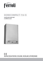
TECHNICAL DATA AND PERFORMANCESOverall dimensionsH321321B1AB21 Plant return3 Plant flow4 Domestic hot water flowFrame 1 Frame 2 Frame 31 1” M 1”1/4 M 1”1/4 M2 1” M 1”1/4 M 1”1/4 M3 1” M 1”1/4 M 1”1/4 MA 730 mm 880 mm 1180 mmB1 730 mm 880 mm 880 mmB2 1630 mm 1810 mm 1810 mmH 1470 mm 1620 mm 1620 mmMinimum operating areaRispect the free area around the unit as shown in figure in order to guaranteea good accessibility and facilitate maintenance and control operations.CD600 mm600 mmDDCC CCOutdoor installationIndoor installation22
The manufacturer declines all the responsabilities regarding inaccuracies contained in this manual, if due to printing or typing mistakes.The manufacturer reserves the right to apply changes and improvements to the products at any time and without notice.23
<strong>Ferroli</strong> spa ¬37047 San Bonifacio (Verona) Italy ¬ Via Ritonda 78/Atel. +39.045.6139411 ¬ fax +39.045.6100933 ¬ www.ferroli.it3QE28300