Fundamentals of Electrogenerated Chemiluminescence (ECL)
Fundamentals of Electrogenerated Chemiluminescence (ECL)
Fundamentals of Electrogenerated Chemiluminescence (ECL)

You also want an ePaper? Increase the reach of your titles
YUMPU automatically turns print PDFs into web optimized ePapers that Google loves.
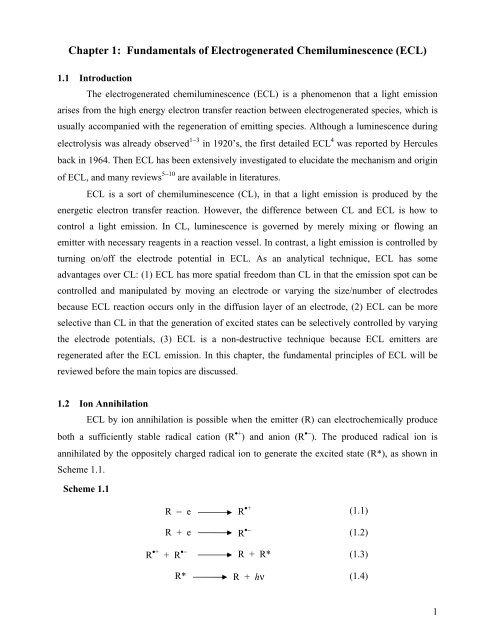
Chapter 1: <strong>Fundamentals</strong> <strong>of</strong> <strong>Electrogenerated</strong> <strong>Chemiluminescence</strong> (<strong>ECL</strong>)1.1 IntroductionThe electrogenerated chemiluminescence (<strong>ECL</strong>) is a phenomenon that a light emissionarises from the high energy electron transfer reaction between electrogenerated species, which isusually accompanied with the regeneration <strong>of</strong> emitting species. Although a luminescence duringelectrolysis was already observed 1−3 in 1920’s, the first detailed <strong>ECL</strong> 4 was reported by Herculesback in 1964. Then <strong>ECL</strong> has been extensively investigated to elucidate the mechanism and origin<strong>of</strong> <strong>ECL</strong>, and many reviews 5−10 are available in literatures.<strong>ECL</strong> is a sort <strong>of</strong> chemiluminescence (CL), in that a light emission is produced by theenergetic electron transfer reaction. However, the difference between CL and <strong>ECL</strong> is how tocontrol a light emission. In CL, luminescence is governed by merely mixing or flowing anemitter with necessary reagents in a reaction vessel. In contrast, a light emission is controlled byturning on/<strong>of</strong>f the electrode potential in <strong>ECL</strong>. As an analytical technique, <strong>ECL</strong> has someadvantages over CL: (1) <strong>ECL</strong> has more spatial freedom than CL in that the emission spot can becontrolled and manipulated by moving an electrode or varying the size/number <strong>of</strong> electrodesbecause <strong>ECL</strong> reaction occurs only in the diffusion layer <strong>of</strong> an electrode, (2) <strong>ECL</strong> can be moreselective than CL in that the generation <strong>of</strong> excited states can be selectively controlled by varyingthe electrode potentials, (3) <strong>ECL</strong> is a non-destructive technique because <strong>ECL</strong> emitters areregenerated after the <strong>ECL</strong> emission. In this chapter, the fundamental principles <strong>of</strong> <strong>ECL</strong> will bereviewed before the main topics are discussed.1.2 Ion Annihilation<strong>ECL</strong> by ion annihilation is possible when the emitter (R) can electrochemically produceboth a sufficiently stable radical cation (R •+ ) and anion (R •− ). The produced radical ion isannihilated by the oppositely charged radical ion to generate the excited state (R*), as shown inScheme 1.1.Scheme 1.1R − e R •+ (1.1)R + e R •− (1.2)R •+ + R •− R + R* (1.3)R* R + hν (1.4)1
Depending on the energy available in an ion annihilation, eq. (1.3), the produced R* could beeither the lowest excited singlet state species ( 1 R*) or the triplet state species ( 3 R*). The energyavailable in eq. (1.3) can be calculated from the electrode potentials for eq. (1.1) and eq. (1.2) asdefined in eq. (1.5) 5 .− ∆H ann = E p (R/R •+ ) − E p (R/R •− ) − 0.1 eV (1.5)where − ∆H ann (eV) is the enthalpy for ion annihilation, E p is the peak potential for theelectrochemical oxidation or reduction, and 0.1 eV is the entropy approximation term (T∆S) at 25°C. If the energy (− ∆H ann ) estimated from eq. (1.5) is larger than the energy (E s ) required toproduce the lowest excited singlet state from the ground state, it is possible to directly generate1 R* from eq. (1.3), and this system is called the energy-sufficient system or the S-route. Thetypical example <strong>of</strong> the energy-sufficient system is the DPA •+ /DPA •− (DPA = 9,10-diphenylanthracene) system. 11,12S-routeR •+ + R •− R + 1 R* (1.3a)In contrast, if − ∆H ann is smaller than E s but larger than the triplet state energy (E t ), 3 R* isinitially formed, and then 1 R* can be formed by the triplet-triplet annihilation (TTA) as shown ineq. (1.6). This is called the energy-deficient system or the T-route. The typical examples <strong>of</strong> theenergy deficient system are TMPD •+ /DPA •− and TMPD •+ /AN •− (TMPD = N,N,N′,N′-tetramethylp-phenylenediamineand AN = anthracene). 11,13 The efficiency <strong>of</strong> direct emission from 3 R* isusually low in a solution phase because <strong>of</strong> the long radiative lifetime <strong>of</strong> 3 R* and its quenching byradical ions or other species, such as molecular oxygen.T-routeR •+ + R •− R + 3 R* (1.3b)3 R* + 3 R* R + 1 R* (1.6)If − ∆H ann is nearly marginal to E s , the T-route can contribute to the formation <strong>of</strong> 1 R* inaddition to the S-route and it is called the ST-route. Although the T-route is inefficient in thepresence <strong>of</strong> considerable S-route, 12,14−16 it is still possible for the ST-route to exist. The typicalexample is the rubrene anion-cation annihilation 17−19 .1.3 CoreactantsA coreactant is a compound that can produce a reactive intermediate (a strong reducing or2
oxidizing agent) by a reaction following the electrochemical or chemical electron transferreaction. Use <strong>of</strong> a coreactant is useful especially when one <strong>of</strong> R •+ or R •− is not stable enough for<strong>ECL</strong> reaction, or when the <strong>ECL</strong> solvent has a narrow potential window so that R •+ or R •− cannotbe formed. In an aqueous solvent, the use <strong>of</strong> a coreactant is very important because water has thenarrow potential window, the low solubility <strong>of</strong> many organic compounds, and many radical ions<strong>of</strong> organic emitters are unstable in an aqueous solvent.The first coreactant used for <strong>ECL</strong> was oxalate ion (C 2 O 2− 4 ). 20,21 When C 2 O 2− 4 is oxidized,it produces the strong reducing agent, CO •− 2 (E° = − 1.9 V vs NHE 22 ), and CO 2 . For example, theaqueous solution <strong>of</strong> Ru(bpy) 2+ 3 can produce <strong>ECL</strong> in the presence <strong>of</strong> C 2 O 2− 4 via Scheme 1.2. Inaddition, aliphatic amines 23−26 and peroxydisulfate (S 2 O 2− 8 ) 27−29 have been used as coreactants.Scheme 1.2Ru(bpy) 3 2+ − e Ru(bpy) 33+(1.7)Ru(bpy) 3 3++ C 2 O 42−C 2 O 4•−Ru(bpy) 3 2+ + C 2 O 4•−(1.8)CO 2 •− + CO 2 (1.9)Ru(bpy) 3 3+ + CO 2•−Ru(bpy) 3 2+ * + CO 2 (1.10)Ru(bpy) 3 2+ + CO 2•−Ru(bpy) 3 + + CO 2 (1.11)Ru(bpy) 3 3+ + Ru(bpy) 3+Ru(bpy) 3 2+ * + Ru(bpy) 32+(1.12)Ru(bpy) 2+ 3 * Ru(bpy) 2+ 3 + hν (1.13)To be a good coreactant, the following conditions should be met: (1) the coreactantshould be reasonably soluble in a solvent because the <strong>ECL</strong> intensity is generally proportional tothe concentration <strong>of</strong> it, (2) the reactive intermediate species generated electrochemically andchemically should be stable enough for the duration <strong>of</strong> the <strong>ECL</strong> experiment, (3) the coreactantshould be easily oxidized or reduced with the <strong>ECL</strong> emitter at or near the electrode and undergo arapid following chemical reaction to form a reactive intermediate, (4) the rate <strong>of</strong> a reactionbetween the intermediate and the radical ion <strong>of</strong> an <strong>ECL</strong> emitter must be rapid, (5) the coreactantand its intermediate should have inert or weak quenching effect on <strong>ECL</strong>, and (6) the coreactantitself should not produce any light emission.1.4 Formation <strong>of</strong> Excimers or ExciplexesIn fluorescence, excimers (excited dimers) are formed by a reaction <strong>of</strong> ground state (R)and excited state (R*) species [eq. (1.14)]. Unlike fluorescence, the direct generation <strong>of</strong> eximers((R 2 )*) can occur in addition to eq. (1.14) during the ion annihilation for <strong>ECL</strong> [eq. (1.15)].3
Depending on the molecular structure <strong>of</strong> R and the lifetime <strong>of</strong> R*, eq. (1.14) may be negligible in<strong>ECL</strong>.R* + R (R 2 )* (1.14)R •− + R •+ (R 2 )* (1.15)Chandross 30 , et. al., first reported the excimer formation <strong>of</strong> 9,10-dimethylanthracene,phenanthrene, perylene, and 3,4-benzpyrene during electrolysis and they suggested that excimermight be mainly formed by eq. (1.15).The excimer can also be formed during the triplet-triplet annihilation (TTA). Bard 31 , et.al. demonstrated the excimer formation <strong>of</strong> pyrene when the radical anion <strong>of</strong> pyrene (Py) wasannihilated by the radical cation <strong>of</strong> TMPD (T-route) at the rotating ring-disk electrode as shownin Scheme 1.3.Scheme 1.3Py •− + TMPD •+3 Py* + 3 Py*3 Py* + TMPD1 Py* + Py(Py 2 )*(1.16)(1.17)(1.18)Similar to the formation <strong>of</strong> excimers, the exciplex (excited complex) can be formed byeqs. (1.19), (1.20), and (1.21). In <strong>ECL</strong>, the exciplex emission arises mainly through eq. (1.19) 32 ,although the mode <strong>of</strong> exciplex formation depends primarily on the energy available in ionannihilation. The singlet quenching path, eq. (1.20), is inefficient in <strong>ECL</strong> unless the excitedsinglet state is produced in proximity <strong>of</strong> D.A •− + D •+ 1 (A − D + )* (1.19)1 A* + D 1 (A − D + )* (1.20)3 A* + 3 D* 1 (A − D + )* (1.21)The emission <strong>of</strong> formed exciplexes may be rationalized by the following scheme 1.4.Scheme 1.4+ hν(1.22)1 (A − ⋅⋅⋅⋅⋅⋅D + )*A + D4
A typical example is the <strong>ECL</strong> <strong>of</strong> PTP •− /TPTA •+(PTP = p-terphenyl and TPTA = tri-ptolylamine)system in acetonitrile. 331.5 Preannihilation <strong>ECL</strong>It was reported that <strong>ECL</strong> was produced when only R •+ or R •− was generated in a solventwithout any coreactants. 34−37 Such luminescence is called as the preannihilation <strong>ECL</strong> and it isusually thought that a light emission may be generated by a reacting species produced fromsolvents, electrolytes, or impurities. For example, when rubrene was electrochemically reduced at− 1.6 V in DMF and then the electrode potential was scanned back to − 0.2 V, a light emissionwas observed. 351.6 Concluding RemarkRecently, <strong>ECL</strong> is <strong>of</strong> great interest for analytical applications as a result <strong>of</strong> its highsensitivity and selectivity. <strong>ECL</strong> produced by a coreactant has been employed in a variety <strong>of</strong> areas:fiber optic <strong>ECL</strong> sensor 38−40 , detection method for HPLC 41−43 , <strong>ECL</strong> biosensing 44−46 , immunoassayand DNA-probe assay analyses 47−49 , and etc. Therefore, it is important to understand <strong>ECL</strong>reaction mechanisms and reactivities <strong>of</strong> coreactants. In this dissertation, the reaction mechanismsand reactivities <strong>of</strong> amine (Chapters 2 and 3) and benzoyl peroxide (Chapters 4 and 5) coreactantsare described for the <strong>ECL</strong> <strong>of</strong> Ru(bpy) 2+ 3 , neutral red, and ter(9,9-diarylfluorene)s.5
References(1) Dufford, R. T.; Nightingale, D.; Gaddum, L. W. J. Am. Chem. Soc. 1927, 49, 1858.(2) Harvey, N. J. Phys. Chem. 1929, 33, 1456.(3) Kuwana, T.; J. Electroanal. Chem. Interfacial Electrochem. 1963, 67, 2243.(4) Hercules, D. M. Science 1964, 145, 808.(5) Faulkner, L. R.; Bard, A. J. In Electroanalytical Chemistry; Bard, A. J., Ed., Marcel Dekker:New York, 1977; Vol. 10, p1.(6) Faulkner, L. R. Methods Enzymol. 1978, 57, 494.(7) Glass, R. S.; Faulkner, L. R. In Chemical and Biological Generation <strong>of</strong> Excited States; Adam,W.; Cilento, G., Eds., Academic Press, New York, 1982, Chapter 6.(8) Knight, A. W.; Greenway, G. M. Analyst 1994, 119, 879.(9) Lee, W. Y. Mikrochim. Acta 1997, 127, 19.(10) Bard, A. J.; Debad, J. D.; Leland, J. K.; Sigal, G. B.; Wilbur, J. L.; Wohlstadter, J. N. InEncyclopedia <strong>of</strong> Analytical Chemistry: Applications, Theory, and Instrumentation, Meyer, R.A. Ed.; John Wiley & Sons: New York, 2000, p. 9842.(11) Faulkner, L. R.; Tachikawa, H.; Bard, A. J. J. Am. Chem. Soc. 1972, 94, 691.(12) Bezman, R.; Faulkner, L. R. J. Am. Chem. Soc. 1972, 94, 6317.(13) Faulkner, L. R.; Bard, A. J. J. Am. Chem. Soc. 1969, 91, 209.(14) Bezman, R.; Faulkner, L. R. J. Am. Chem. Soc. 1973, 95, 3083(15) Bezman, R.; Faulkner, L. R. J. Am. Chem. Soc. 1972, 94, 6324.(16) Bezman, R.; Faulkner, L. R. J. Am. Chem. Soc. 1972, 94, 6331.(17) Tachikawa, H.; Bard, A. J. Chem. Phys. Letters 1974, 26, 246.(18) Periasamy, N.; Santhanam, K. S. V. Proc. Ind. Acad. Sci. 1974, 80A, 821.(19) Pighin, A.; Conway, B. E. J. Electrochem. Soc. 1975, 122, 619.(20) Chang, M. −M.; Saji, T.; Bard, A. J. J. Am. Chem. Soc. 1977, 99, 5399.(21) Rubinstein, I.; Bard, A. J. J. Am. Chem. Soc. 1981, 103, 512.(22) Butler, J.; Hengline, A. Radiat. Phys. Chem. 1980, 15, 603.(23) N<strong>of</strong>fsinger, J. B.; Danielson, N. D. Anal. Chem. 1987, 59, 865.(24) Leland, J. K.; Powell, M. J. J. Electrochem. Soc. 1990, 137, 3127.(25) Zu, Y.; Bard, A. J. Anal. Chem. 2000, 72, 3223.(26) Kanoufi, F.; Zu, Y.; Bard, A. J. J. Phys. Chem. B 2001, 105, 210.(27) White, H. S.; Bard, A. J. J. Am. Chem. Soc. 1982, 104, 6891.(28) Becker, W. G.; Seung, H. S.; Bard, A. J. J. Electroanal. Chem. 1984, 167, 127.(29) Fabrizio, E. F.; Prieto, I.; Bard, A. J. J. Am. Chem. Soc. 2000, 122, 4996.6
(30) Chandross, E. A.; Longworth, J. W.; Visco, R.E. J. Am. Chem. Soc. 1965, 87, 3259.(31) Maloy, J. T.; Bard, A. J. J. Am. Chem. Soc. 1971, 93, 5968.(32) Bard, A. J.; Park, S. M. In The Exciplex; Gordon, M.; Ware, W. R., Eds.; Academic Press:New York, 1975, p. 305.(33) Keszthelyi, C. P.; Bard, A. J. Chem. Phys. Letters 1974, 24, 300.(34) Hercules, D. M.; Lansbury, R. C.; Roe, D. K. J. Am. Chem. Soc. 1966, 88, 4578.(35) Maricle, D. L.; Maurer, A. J. Am. Chem. Soc. 1967, 89, 188.(36) Zweig, A.; H<strong>of</strong>fman, A. K.; Maricle, D. L.; Maurer, A. H. Chem. Commun. 1967, 106.(37) Zweig, A.; Maricle, D. L.; Brinen, J. S.; Maurer, A. H. J. Am. Chem. Soc. 1967, 89, 473.(38) Egashira, N.; Kumasako, H.; Ohga, K. Anal. Sci. 1990, 6, 903.(39) Kuhn, L. S.; Weber, A.; Weber, S. G. Anal. Chem. 1990, 62, 1613.(40) Preston, J.; Nieman, T. A. Anal. Chem. 1996, 68, 966.(41) N<strong>of</strong>fsinger, J. B.; Danielson, N. D. J. Chromatogr. 1987, 387, 520.(42) Uchikura, K.; Kirisawa, M. Anal.Sci. 1991, 7, 971.(43) Skotty, D. R.; Lee, W. Y.; Nieman, T. A. Anal. Chem. 1996, 68, 1530.(44) Martin, A. F.; Nieman, T. A. Anal. Chim. Acta 1993, 281, 475.(45) Yokoyama, K.; Sasaki, S.; Ikebukuro, K.; Takeuchi, T.; Karube, I.; Tokitsu, Y.; Masuda, Y.Talanta 1994, 31, 1035.(46) Jameison, F.; Sanchez, R. I.; Dong, L.; Leland J. K.; Yost, D.; Martin, M. T. Anal. Chem.1996, 68, 1298.(47) Blackburn, G. F.; Shah, H. P.; Kenten, J. H.; Leland, J.; Kamin, R. A.; Link, J.; Peterman, J.;Powell, M. J.; Shah, A.; Talley, D. B.; Tyagi, S. K.; Wilkins, E.; Wu, T. G.; Massey, R. J.Clin. Chem. 1991, 37, 1534.(48) Kenten, J. H.; Casadei, J.; Link, J.; Lupold, S.; Willey, J.; Powell, M. J.; Rees, A.; Massey,R. J. Clin. Chem. 1991, 37, 1626.(49) DiCesare, J.; Grossman, B.; Katz, E.; Picozza, E.; Ragusa, R.; Woundenberg, T.Biotechniques 1993, 15, 152.7