installation instructions for symcom's motorsaver model 520cp
installation instructions for symcom's motorsaver model 520cp
installation instructions for symcom's motorsaver model 520cp

Create successful ePaper yourself
Turn your PDF publications into a flip-book with our unique Google optimized e-Paper software.
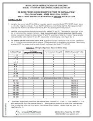
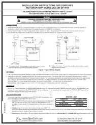
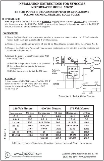
INSTALLATION INSTRUCTIONS FOR SYMCOM'SMOTORSAVER MODEL 520CPBE SURE POWER IS DISCONNECTED PRIOR TO INSTALLATION!!FOLLOW NATIONAL, STATE AND LOCAL CODES!!!! ATTENTION !!!Turn off power to the 520CP or 520CS BEFORE plugging in the 520RD. DO NOT plug the 520RDinto the socket when the 520CP or 520CS is powered-up Loss of set points may occur if the 520CPor 520CS has its L1 and L2 terminals energized.CONNECTIONS1. Mount the MotorSaver in a convenient location in or near the motor control box. If the location iswet or dusty, then use a NEMA 3R, 4 or 12 enclosure.2. Connect the control panel power to L1 and L2 on MotorSaver’s terminal strip. See Figure No. 1.3. Connect the MotorSaver’s normally open output contacts in series with the magnetic contactor coilas shown in Figure No. 1.4. Ensure the proper Current Trans<strong>for</strong>mer (CT)size using Table 1.A) Find the voltage of the motor to be protected.B)Move down the column to the correcthorsepower.C) Follow the row over to find the CT size.INPUT POWERL1L2L3MMMCT1 CT2 CT3 CTCREMOTE RESETL1L2OLOLOLOLMOTORMAG.COILEXAMPLE:A three-phase, 2HP, 230V motor. Find the 230 Vcolumn and move down to the 2HP row. Moveacross the row and read the CT size - 50:5(read 50 to 5).STOPHANDOFFSTARTMAUTOPILOTFigure No. 1: Typical Wiring Diagram.230 Volt Motors400 Volt Motors575 Volt MotorsHorsepowerCT SizeHorsepowerCT SizeHorsepowerCT Size.5 - 15:5.5 - 12.5:5.5 - 12.5:51.5 - 550:51.5 - 25:51.5 - 35:57.5 - 2075:53-10, 25-3050:55-15, 3050:525 - 30100:515-20, 4075:520-25, 40-5075:540150:550-60100:560-75100:550 - 60200:575150:5100150:575 - 125400:5100-125200:5125-150200:5150-260400:5200-325400:5Table No. 1: Current Trans<strong>for</strong>mer Selection - Squirrel Cage and Wound Rotor Motors2880 North Plaza Drive, Rapid City, SD 57702 • (800) 843-8848
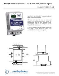
5. Determine the number of loops required. A CT operates best if the current it is sensing is between60% and 80% of its range. Multiply the motor operating current by a number which will result in thenew multiple being between 60% and 80% of the upper limit of the CT. [The upper limit of the CT isthe number in front of the colon (:) in the CT designator.] The multiplier is the number of loops.EXAMPLE: A 230V, 2 Hp motor has a normal operating current of 6.8 A. From Table No. 1, a 50:5CT is required. The range we are looking <strong>for</strong> is between 30A and 40A (60% of 50 and 80% of 50). Ifwe multiply 6.8A times 5, we have 34A. {6.8A x 4 = 27.2A which is out of the 60%-80% range and6.8A x 6 = 40.2A which is also out of the 60%-80% range}. There<strong>for</strong>e, we should make 5 loopsthrough the center of the CT.6. Calculate the normal CT current. Multiply the motor operating current by the number of loopsthrough the CT and divide by the CT ratio. The CT ratio is the upper limit of the CT divided by themaximum CT current (e.g., a 50:5 CT has a upper limit of 50 and a maximum CT current of 5.There<strong>for</strong>e, the CT ratio is 50÷5 or 10).EXAMPLE CONTINUED: We determined that the 230V, 2 Hp motor needs 5 loops through a 50:5 CT.The CT ratio is 50÷5=10. We multiply the normal operating current by the number of loops and divideby the CT ratio...(6.8x5)÷10 = 3.4A. The normal CT current is 3.4A. This is the current the CT willoutput when the motor is running normally.7. Run the motor’s supply wires through the CTs the required number of loops as determined in step 5.A loop is defined as one pass of the supply wire through the center of the CT. The CT side marked“HI” should face away from the motor. Each CT should have one supply wire running through its center.8. Connect each of the three black CT leads to one of MotorSaver’s “CT1”, “CT2” and “CT3” terminals.Connect the white CT leads together at MotorSaver’s “CTC” terminal. See Figure No. 1.9. Connect a remote reset button to the "Remote Reset" terminals if desired.MESSAGE“OFF” Flashing“run” Flashing“run” Steady“oc” Flashing“oc” Steady“uc” Flashing“uc” Steady“SP” Flashing“SP” Steady“rP” Flashing“rP” Steady“ub” Flashing“ub” SteadySTATUS INDICATIONIn power-up delay (RD1)Contacts are energized, waiting <strong>for</strong> motor start-up currentIn motor acceleration period (4 seconds)Tripped on OverCurrent, waiting <strong>for</strong> RD 2 minutesTripped on OverCurrent #RF timesTripped on UnderCurrent, waiting <strong>for</strong> RD 3 minutesTripped on UnderCurrent #RU timesTripped on Single Phasing, waiting <strong>for</strong> RD 2 minutesTripped on Single Phasing #RF timesTripped on Reverse Phasing, waiting <strong>for</strong> RD 2 minutesTripped on Reverse Phasing #RF timesTripped on current UnBalance, waiting <strong>for</strong> RD 2 minutesTripped on current UnBalance #RF timesPROGRAMMING THE MODEL 520CP1. Select the feature to program by rotating the “MODESELECT” screw to the desired position.“OC” - OverCurrent set point“UC” - UnderCurrent set point“UB” - current UnBalance set point“TD” - Trip Delay set point“RD1” - Restart Delay on power-up (Rapid Cycle Timer)“RD2” - Restart Delay after all faults except undercurrent“RD3” - Restart Delay after undercurrent“#RF” - Number of Restarts after all faults“#RU” - Number of Restarts after an undercurrent faultMODEL 520CPRD1TD RD2UBRD3UC#RFMINIMUM MAXIMUMOC #RURUNCALIBRATIONDISPLAY MESSAGEMODE SELECT- RUN- SINGLE PHASE- OVER CURRENT - REVERSE PHASE- UNDER CURRENT - CURRENT UNBALANCERESET/PROGRAM2. Push and hold the “RESET/PROGRAM” button.3. Rotate the “CALIBRATION” screw to the desired setting of the feature as shown in the LED display.Release the “RESET/PROGRAM” button.4. Continue steps 1-3 until all features are programmed.08/02 - 2 -
SUGGESTED SETTINGS(Consult the motor manufacturer <strong>for</strong> their recommendations.)1. The recommended settings <strong>for</strong> “OC” (overcurrent) and “UC” (undercurrent) depend on manyfactors such as motor usage, motor size, environmental factors and tolerance of the motor.The motor manufacturer should be consulted <strong>for</strong> “OC” and “UC” settings. However, “OC” istypically set between 110% and 125% of Full Load current. “UC” is typically set at 80% of Full Loadcurrent. The setting can be determined by following Installation instruction #5 and #6 andmultiplying by the % over and under desired.2. Most motor manufacturers recommend operating under no more than 5% current unbalance.There<strong>for</strong>e, SymCom suggests starting with “UB” set at 5%.3. “TD” is the trip delay. Since most motors can be damaged by poor power in a very short time,setting “TD” between 2.0 and 10.0 seconds is typical. However, the application and powerconditions will affect the decision about the setting of “TD”. NOTE: The Model 520CS will trip onsingle phasing and reverse phasing faults in 0.5 seconds regardless of the “TD” setting. Also, theModel 520CP will trip faster than “TD” on an overcurrent fault as shown on the “Over CurrentInverse Time Curve” in the specification sheet.4. “RD1” acts as a rapid cycle timer. The setting of “RD1” depends on the application. Generally, asetting of 20 to 30 seconds will absorb successive rapid power outages and prevent on-off-on-offoperation of the motor. A setting of 0 allows the motor to restart immediately after a normal powershut-down.5. “RD2” is the restart delay after all faults except undercurrent. The setting of “RD2” is dependentupon the “#RF” setting, the application and the motor manufacturer’s recommendations. Generally,the higher the setting of “#RF” the higher the “RD2” setting.6. “RD3” is the restart delay after an undercurrent fault. “RD3” is normally set <strong>for</strong> the time required <strong>for</strong>the well to recharge. As with the other timer settings, “RD3” is dependent on the application.7. “#RF” is the number of times the output contacts will close after the same fault has occurred insuccession. The setting of “#RF” depends on the application, “RD2” setting and the motor manufacturer’s recommendations. “#RF” can be set to 0,1,2,3,4 or 999. A setting of “0” is manual reset.A setting of “999” is unlimited retries.8. “#RU” is the number of times the output contacts will close after undercurrent faults occur insuccession. Typically, an undercurrent fault on a submersible pump means a dry well situation.There<strong>for</strong>e, “#RU” is usually set to “999” or unlimited number of retries. However, “#RU” can be set to0,1,2,3,4 or 999. A setting of “0” is manual reset. As with all other settings, “#RU” should be setaccording to the motor manufacturers recommendations.OPERATIONOnce the Model 520CP has been programmed, turn the “MODE SELECT” switch to the “RUN”position. The LED display will flash “OFF” <strong>for</strong> the period of time set in the “RD1” setting. After thispower-up delay, the output contacts will close and the LED display will flash “run” until the motor starts.After the 520CP senses motor current, the LED display will show “run” steadily during the userprogrammedmotor acceleration period (MA). Following the motor acceleration period, the LEDdisplay will show the average of the three CT currents. If any message sequence other than thatdescribed above occurs the first time the motor is started, see TROUBLESHOOTING below.TROUBLESHOOTINGPROBLEM“rP” is displayed on initial start-up“SP” is displayed on initial start-up“uB” is displayed on initial start-up“oC” or “uC” is displayed on initial start-upContinual tripping on “uC”SOLUTION1. Swap any two of CT1, CT2 and CT3.2. Make sure that all CT sides marked “HI”are pointed away from the motor.3. If splices are made, check the splices to ensure the electricalintegrity, use larger wire or shorten the run of the wire.4. Move the CTs to the line side of a Variable Frequency Drive.See steps 2 and 4 above.Check to make sure the same # of loopsare made through all of the CTs.Check <strong>for</strong> proper CT sizing <strong>for</strong> the motorand the proper number of loops.Increase the number of loops to reach the 60%-80% window- 3 - 08/02
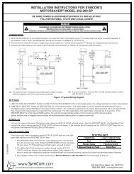
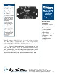
Trip Delay Timer (as % of TD settings)20015010050Typical OverCurrent Inverse Time Trip CurvesTD = 50 Sec.TD = 2 Sec.TD = 5 Sec.00 100 200 300 400Percent OverLoadTD = 10 Sec.TD = 20 Sec.Model 520CP SPECIFICATIONSControl VoltageFrequencyCurrent Trans<strong>for</strong>mersMaximum Full Scale CurrentOperating PointsFixed SettingsReverse Phase Trip DelaySingle Phase Trip Delay100 to 130 VAC (MS520CP-115)200 to 250 VAC (MS520CP-230)400 to 500 VAC (MS520CP-460)550 to 600 VAC (MS520CP-575)50 - 60 HzAvailable from SymCom, Inc.5 Amp Max. Secondary0.5 Seconds0.5 SecondsProgrammable SettingsRange (Increment)"OC" OverCurrent Trip Point (Overload) UnderCurrent Trip - 5.00 (0.02)"UC" UnderCurrent Trip Point 0.00 - OverCurrent Trip (0.02)"UB" Current UnBalance Trip Point 2.0 - 50.0% (0.2)"TD" Trip Delay (except Phasing and2.0 - 50.0 Seconds (0.2)OverCurrent faults - see inverse timecurve <strong>for</strong> OverCurrent trip delay)"RD1" Restart Delay on Power-Up 0 - 500 Seconds (2)(Rapid Cycle Timer)"RD2" Restart Delay after all Faults except 2 - 500 Minutes (2)UnderCurrent (Motor Cool Down Timer)"RD3" Restart Delay after UnderCurrent 2 - 500 Minutes (2)(Dry Well Recovery Timer)"#RF" Number of Restarts after all Faults 0, 1, 2, 3, 4 or 999 (Unlimited)"#RU" Motor Acceleration Time 0, 1, 2, 3, 4 or 999 (Unlimited)Fixed Operating PointReverse Phase and Single Phase Trip Delay 0.5 Sec.Temperature Range0 to 70° CelsiusOutput Contact Rating480 VA @ 240 VAC(Models MS520CP115 and MS520CP230)(SPDT)470 VA @ 600 VAC(Models MS520CP460 and MS520CP575)Transient Protection (Internal)2500 Volts <strong>for</strong> 10 mSecondsRepeat AccuracyTrip Point ± 2%Timing± 25%, ±1 Sec.Power Consumption5 Watts (Max.)Weight2 lbs.Special Options on Model 520CPDPDT RelayA remote display is available <strong>for</strong> the 520CP series MotorSaver. Order 520CP-xxx-RJ and remote display partnumber 520RD. The 520RD allows all the 520CP programmable functions and actual motor running amperageto be viewed without opening the panel. Call your Distributor or SymCom <strong>for</strong> details today!!!Seller warrants to the buyer that products furnished will be free from defects in material and workmanship, exclusive of corrosion, <strong>for</strong> aperiod of one year from the date of shipment from its factory, provided said products have been installed, maintained and operated incon<strong>for</strong>mance with any applicable specifications and recommendations of the Seller. The sellers liability under this warranty shall be limitedto the replacement within the a<strong>for</strong>esaid time of any defective work or material limited at the Seller’s factory and shall not be liable <strong>for</strong> anylabor or other repair costs made outside the Seller’s factory without the written consent of the Seller. The Seller shall be liable <strong>for</strong> no otherdamages or losses. The warranty described in this paragraph shall be IN LIEU OF ANY OTHER WARRANTY EXPRESSED OR IMPLIEDINCLUDING BUT NOT LIMITED TO ANY IMPLIED WARRANTY OF MERCHANTABILITY OR FITNESS FOR A PARTICULAR PURPOSE.08/02 - 4 -