Series PGL Laminar Flow Diffusers - Keane Environmental
Series PGL Laminar Flow Diffusers - Keane Environmental
Series PGL Laminar Flow Diffusers - Keane Environmental

Create successful ePaper yourself
Turn your PDF publications into a flip-book with our unique Google optimized e-Paper software.
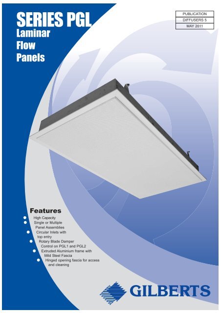
SERIES <strong>PGL</strong>IntroductionGilberts <strong>Series</strong> <strong>PGL</strong> provides a range of <strong>Laminar</strong> <strong>Flow</strong>Panels are suitable for use in operating theatres,laboratories, clean rooms and other similar applications.Unlike a conventional ceiling diffuser the <strong>Laminar</strong> <strong>Flow</strong> Panelprovides an equalised turbulence free input of air into thetreated zone creating a vertical air projection with little in theway of back drafts or inter-mixing. In this way a clean uncontaminatedair zone can be supplied to surround criticalareas ie: operating tables and work tops. These units aremainly used for cooling or isothermal conditioning becauseof the buoyancy effect of the supply air and, unless low levelextract is provided, under heating conditions largetemperature differentials will occur between the floor andceiling levels.<strong>Laminar</strong> <strong>Flow</strong> Panels are available either in multiple format<strong>PGL</strong>1 for coverage of large zonal areas or as individual units<strong>PGL</strong>2 for discreet supplies throughout the space. The <strong>PGL</strong>2units are also offered with three different types of border tosuit current popular ceiling designs.TYPE <strong>PGL</strong> 1 - <strong>Laminar</strong> <strong>Flow</strong> diffuser designed to form multiple panel assembly.TYPE <strong>PGL</strong> 2 - Single unit <strong>Laminar</strong> <strong>Flow</strong> diffuser with 32mm flange border frame.TYPE <strong>PGL</strong> 2/T - Single unit <strong>Laminar</strong> <strong>Flow</strong> diffuser with tegular border frame.TYPE <strong>PGL</strong> 2/B - Single unit <strong>Laminar</strong> <strong>Flow</strong> diffuser with clip in border frame.The perforated diffuser face has a low free area,approximately 15%, with standard unit sizes being600 x 600, 900 x 600 and 1200 x 600 with models to fit inboth plasterboard ceilings and modern ceiling grids. Theunits are manufactured from an extruded aluminium frameand mild steel perforated face with the Plenum chambers insteel zintec. The diffuser is finished as standard in a whitepolyester powder coating. In <strong>PGL</strong>1 format the unit can, infact, be built up to form a complete <strong>Laminar</strong> <strong>Flow</strong> ceiling withappropriate location points for light fittings and otherservices. Volume control can be achieved on both <strong>PGL</strong>1 and<strong>PGL</strong> 2 by fitting a rotary damper to the plenum inlet spigot ofeach panel with access for adjustment by removal of the faceplate.Duct mounted volume control dampers for balancing canalso be supplied in quadrant or iris designs, with circularconnections standard on all types.Features● High capacity● Single or Multiple panel assemblies● Circular inlets with top entry● Rotary Blade damper control on<strong>PGL</strong>1 and <strong>PGL</strong>2 units● Extruded aluminium frame andmild steel fascia● Hinged opening fascia for accessand cleaningSelectionProcedureFirstly the following parameters must be established:A Total air volume for space to be conditioned.B Ceiling HeightC Maximum temperature differential (generallyon cooling). Please note that very little throwis achieved using these units for heatingonly in the higher volume ranges.D Throws required vertically, generally to theoccupied zone. This must correspond to therequired terminal velocities.E Maximum noise levels. Please note that data is onlyavailable down to NC20.Having established the above parameters, select a unit fromthe performance data to correspond with the noise level andthrow requirements. From this selection note the air volumeper unit. Divide this air volume into the total air volume for thespace and thus arrive at a total number of supply units.EXAMPLE:A Total volume for space 2 m 3 /sB 3m ceiling heightC 5°C cooling maximumD Throws required are 2.5m to 0.25m/s and 1.5mto 0.5m/sE Maximum noise level NC 30From 5°C cooling section on chart, select unit with a totalvolume of 0.15m 3 /s. Check other parameters ie: staticpressure 4 Pa, NC 20, throws 1.5 to 2.5. Now divide 2m3/s by0.15m3/s which equals 13.33 units (rounded up to 14). Theseunits must now be distributed evenly across the ceiling areato give the best possible coverage over the entire space.2<strong>Laminar</strong> <strong>Flow</strong> Panels
SERIES <strong>PGL</strong><strong>Series</strong> <strong>PGL</strong> 1Assembly Type 1Assembly Type 13m x 3m design3000mm1200 x 600Panels25 mm Plasterboardflanges (see detailon page 4)3000mmCircularconnection oneach panelOptionalrotarydamperJoining hole positionsvary for each unit<strong>PGL</strong>/11200 x 600panels50 mmspigot112 mmIllustration of open unitEnd view<strong>Laminar</strong> <strong>Flow</strong> Panels3
SERIES <strong>PGL</strong><strong>Series</strong> <strong>PGL</strong> 1Assembly Type 2Assembly Type 23m x 2.4m design3000mm1200 x 600Panels900 x 600PanelsCentral blankingplate supplied in2 halves. Holefor light fittingcut by others2400mmCircularconnectionson eachpanelPlaster ceilingedge detailOptional rotarydamper<strong>PGL</strong>/1900 x 600panelThe 25mm Plaster Board flanges are set back 3mmfrom face of the diffuser. They are designed to pushup against the plasterboard and leave enough depthfor a skim of surface plaster to hide / conceal.<strong>Series</strong> <strong>PGL</strong> 1Assembly Type 3AssemblyType 31.8m x 1.2mdesign1200mm1200 x 600Panels1800mm<strong>Series</strong> <strong>PGL</strong> 1Assembly Type 4AssemblyType 43.6m x 0.6mdesign600mm1200 x 600 Panels3600mm4<strong>Laminar</strong> <strong>Flow</strong> Panels
SERIES <strong>PGL</strong><strong>Series</strong><strong>PGL</strong>/2/TTegularCeilingThe <strong>PGL</strong>/2/T option for the laminar flow diffuser features aborder frame specially designed to suit modern ‘tegular’type ceiling grids. This border, available on <strong>PGL</strong>/2/T unitsfeatures a factory adjusted edge detail to suit drops ofbetween 7 - 19mm allowing it to match with most popularceiling types (please provide full ceiling details).Adj. from7 - 19mmpleasespecifyFace Size<strong>Series</strong><strong>PGL</strong>/2/BClip-inCeilingThe <strong>PGL</strong>/2/B option for the laminar flow diffuser features aborder frame specially designed to suit popular clip-in typeceiling grids. Simply specify the ceiling pip height(normally 19 or 25mm) or provide full details of ceiling andwe will include appropriate location/alignment clips to suit.Pip Height(Please specify)Overall Size = FaceSize +10mmList Size -1mmType <strong>PGL</strong>2/T Tegular CeilingType <strong>PGL</strong>2/B Clip in CeilingTegular Unit Sizes (W x H)List Size 1200 x 600 Face Size 1184 x 584or Face Size 1174 x 574List Size 900 x 600 Face Size 884 x 584or Face Size 874 x 574List Size 600 x 600 Face Size 584 x 584or Face Size 574 x 574Face size to be specified to suit ceilingOverall size = Face size + 10mmClip-In Unit Sizes (W x H)1200 x 600 mm900 x 600 mm600 x 600 mmRotaryDampersThe Rotary damper is a new alternative to fitting aquadrant damper on the plenum inlet allowing damperadjustment from the diffuser face. The damper can simplybe manually adjusted/rotated to the required position usingthe tabs on the damper face.For access to the damper the hinged diffuser face mustfirst be opened.6<strong>Laminar</strong> <strong>Flow</strong> Panels
SERIES <strong>PGL</strong>Sizing andPerformanceDataISOTHERMAL CONDITIONSVolume m 3 /s 0.05 0.10 0.15 0.2 0.25 0.3 0.35NC Level 20 20 25 30 35 40Static Pressure Pa 1 2 4 7 14 18 23Throw m 0.5-1.0 0.8-1.3 0.8-1.5 0.9-1.8 1.5-2.0 1.8-2.2 2.0-2.35°C COOLINGVolume m 3 /s 0.05 0.10 0.15 0.2 0.25 0.3 0.35NC Level 20 20 25 30 35 40Static Pressure Pa 1 2 4 8 14 18 23Throw m 1.0-2.0 1.3-2.3 1.5-2.5 1.6-2.5 1.8-2.8 2.0-3.0 2.2-3.510°C COOLINGVolume m 3 /s 0.05 0.10 0.15 0.2 0.25 0.3 0.35NC Level 20 20 25 30 35 40Static Pressure Pa 1 2 4 6 14 18 23Throw m 1.2-2.2 2.0-2.5 2.2-2.8 2.3-3.0 2.5-3.2 2.8-3.5 3.0-4.05°C HEATINGVolume m 3 /s 0.05 0.10 0.15 0.2 0.25 0.3 0.35NC Level 20 20 25 30 35 40Static Pressure Pa 7 14 18 23Throw m 0.5-0.8 0.5-1.0 1.3-1.6 1.4-1.810°C HEATINGVolume m 3 /s 0.05 0.10 0.15 0.2 0.25 0.3 0.35NC Level 20 20 25 30 35 40Static Pressure Pa 7 14 18 23Throw m 0.5-0.8 0.5-1.0 0.8-1.2 1.2-1.5Angle ofdischarge12°fromverticalVerticaldischargeVerticaldischargeAngle ofdischarge12° fromverticalAngle ofdischarge12° fromverticalTHROW: First figure corresponds to 0.5m/s, second Figure to 0.25m/s (max figures)NC LEVELS: No room correction figures have been deductedSIZE: Tables based on 1200 x 600 panelNote:For 600 x 600 Units:-For 900 x 600 Units:-1 Double the volume per panel and use figures above.2 Reduce throw by 1/3rd3 NC Levels take as above but for double the volume4 Circular connection (200 diameter)1 Increase the volume per panel by 1/3rd and use figures above.2 Reduce throw by 1/6th3 NC Levels take as above with volume per panel increased by 1/3rd4 Circular connection (250 diameter)Gilberts Supply <strong>Diffusers</strong> have been tested within the range of +/- 10ºC (as recommended in the HEVACGuide to Air Distribution Technology). For any other temperature differential requirements please contactour Technical Department.<strong>Laminar</strong> <strong>Flow</strong> Panels7
SERIES <strong>PGL</strong>OrderingSpecificationSERIES: <strong>PGL</strong>1, <strong>PGL</strong>2<strong>PGL</strong>2/T, <strong>PGL</strong>2/BSIZE DETAILASSEMBLY TYPE (<strong>PGL</strong>1 Only)A1, A2, A3 or A4ORLIST SIZE mm (<strong>PGL</strong>2 Only)<strong>PGL</strong>1 A1 1184 X 584 315 TD8 PIP19 DR PPC RAL9010 20%2GLOSSFACE SIZE mm(Applies to <strong>PGL</strong>2/T only)SPIGOT SIZE1200 x 600 - 315mm Nom Dia900 x 600 - 250mm Nom Dia600 x 600 - 200mm Nom DiaTEGULAR DROP DEPTH (mm)<strong>PGL</strong>/2 'T' only - TD + DepthPIP HEIGHT (<strong>PGL</strong>2/B only)PIP + Height (mm)DAMPER OPTIONSRotary ................................. DRFINISH(please specify)NUMBER REQUIREDNote - All units are supplied with circular top inlet connection as standard.1200 x 600 - 315 Dia inlet900 x 600 - 250 Dia inlet600 x 600 - 200 Dia inletWhere assembly type 1 to 4 is ordered please detail spigot sizes where different from standardfor each unit / module.FINISHSTANDARD FINISH:Polyester Powder White RAL 901020% gloss. NB. Plenum Box supplied -natural zintec finish.FIXINGStandard fixing for all units is via droprods (by others) to 8mm diameterholes in the angle cleatsat the rear.SPECIAL FINISHES:Polyester Powder Finish to stock BS/RALcolour.ContactGILBERTSHead Office and WorksGILBERTS (BLACKPOOL) LTDGilair Works, Clifton Road,Blackpool.Lancashire FY4 4QT.Telephone: (01253) 766911Fax: (01253) 767941e-mail: sales@gilbertsblackpool.comWeb: www.gilbertsblackpool.comGilberts (Blackpool) Ltd reserve the right to alter the specification without notice. For our latest product data please visit www.gilbertsblackpool.comThe information contained in this leaflet is correct at time of going to press © 2011.