Basic Stability for Small Vessels - Shipowners
Basic Stability for Small Vessels - Shipowners
Basic Stability for Small Vessels - Shipowners

You also want an ePaper? Increase the reach of your titles
YUMPU automatically turns print PDFs into web optimized ePapers that Google loves.
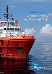
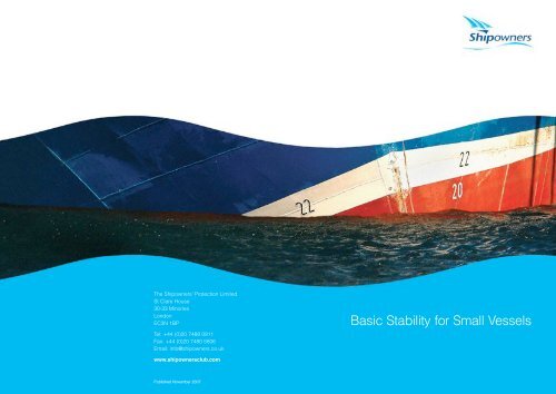
The <strong>Shipowners</strong>’ Protection LimitedSt Clare House30-33 MinoriesLondonEC3N 1BPTel: +44 (0)20 7488 0911Fax: +44 (0)20 7480 5806Email: info@shipowners.co.uk<strong>Basic</strong> <strong>Stability</strong> <strong>for</strong> <strong>Small</strong> Ve s s e l swww.shipownersclub.comPublished November 2007
Index2 Introduction4 Lack of Understanding of <strong>Stability</strong> Criteria6 <strong>Stability</strong> Requirements14 Failure to Observe <strong>Basic</strong> Principles16 Pre Load Requirements16 Free Surface Effect17 Estimating Centre of Gravity17 Container Heights17 Container Weights18 Draft19 Cranes and Derricks20 Overloading20 Reductions in Freeboard21 Failure to Confirm the Vessel’s Condition22 Errors in Calculations24 Computers27 Conclusion28 Appendices30 Appendix 1: Pro<strong>for</strong>ma Calculation Sheet (VCG)31 Appendix 2: Examples of Calculating <strong>Stability</strong> Conditions42 Case Studies1
IntroductionI n t ro d u c t i o nMany different types of vessels are entered in the Club, each possessing their own uniquestability requirements.Generally speaking tankers, bulk carriers and passenger vessels retain more than sufficientstability to ensure compliance with the regulations when fully loaded. Dry cargo ships,container carriers and barges are subject to large reductions in stability when loadedthere<strong>for</strong>e care must be taken to ensure the condition of the vessel complies with theregulations which lay down the minimum stability requirements. If these are not complied with,then the safety of the vessel, her crew and cargo will be compromised.Over the years the Club has dealt with a number of claims involving general cargo vesselsand container ships that have been caused by the vessel having inadequate stability andbeing allowed to undertake a voyage in that condition. There have also been a large numberof similar incidents involving flat top barges loaded with break bulk, containers, scrap metal orcombinations of all three. In most cases the lack of sufficient stability has not been madeapparent until an external <strong>for</strong>ce has acted on the vessel caused by heavy sea conditions, asharp alteration of course or the pushing of an assisting tug.Prompted by these claims, the Club has published this booklet on basic stability aimedprimarily at Members and crews of dry cargo vessels. The purpose of the booklet is to explainthe fundamentals of stability and explanations as to how it can be determined which is notalways readily understood by crews and personnel responsible <strong>for</strong> loading vessels. All tooften the GM is taken to be the measure of a vessel’s stability and this is an incorrectassumption.Notwithstanding the type of dry cargo vessel or barge, the predominant cause of claims wesee is a lack of adequate transverse stability on vessels carrying containers. Although themajority of incidents occurred either on specific container vessels or cargo vessels carryingcontainers, stability issues are equally important on all types of vessels. Fortuitously mostincidents have not resulted in a total loss. This is mainly because as the vessels listed over,the cargo has fallen overboard and positive stability was regained, allowing the vessel toreturn to near upright. In other cases, the vessels developed an angle of loll and upon arrivalin port, with the assistance of the authorities, the upper tiers of containers were removed andpositive stability was regained by lowering the overall KG. If a vessel were to experience theserious effects of insufficient stability whilst in a heavy sea where dynamic stability is crucial,the results may not be so <strong>for</strong>tunate with loss of the vessel and life a real possibility.The Club has also dealt with claims arising from flat barges carrying scrap metal. In eachcase the vessel capsized but did not sink, but in all probability the cause was inadequatestability compounded by the shifting of cargo.CausesWe have found it rare that an unsatisfactory situation regarding the vessel’s stability developsthough a single cause. In our experience it usually arises through a collection of one or moreof the following factors:-! Lack of understanding of the stability criteria! A failure to observe basic principles! Arithmetical errors in calculationsAppendix 2 contains a number of stability calculation examples and the Case Studiesdescribe the circumstances leading to actual related claims dealt with by the Club.2 3
Lack of Understandingof <strong>Stability</strong> Criteria4 5
Lack of Understanding of <strong>Stability</strong> CriteriaDuring investigations into claims, we have found that there have been occasions when thesenior officers responsible <strong>for</strong> cargo operations were not familiar with the vessel’s stabilitymanuals, or the onboard Class approved stability/loading instrument program. Members andMasters must ensure that all personnel involved in cargo operations make themselvest h o roughly familiar with the contents of the stability manual and the operating parameters there i n .<strong>Stability</strong> RequirementsThe IMO has issued minimum stability criteria <strong>for</strong> different types of vessel and these criteriaare taken into account at the vessel’s design stage and when calculating the data <strong>for</strong> thestability book.Sea staff and shore personnel involved with marine operations are usually aware of theminimum permitted height <strong>for</strong> the GM and can mistakenly use this as the sole measure of avessel’s stability. However, this is only one single criterion, and compliance with this alone isnot enough to guarantee adequate stability. There are other equally or more important factorswhich have to be taken into account to ensure that the vessel has sufficient positive stability<strong>for</strong> the voyage. In the Club’s experience these other limitations are not always fully understoodor taken into account.Utilising the vessel’s stability data, the Curve of Statical <strong>Stability</strong> can be drawn and from thisthe vessel’s dynamical stability can be determined. Dynamic stability is the ability of a vesselto resist or overcome external heeling <strong>for</strong>ces and is directly proportional to the areaunderneath the curve of statical stability. Thus the more dynamic stability a vessel has, thegreater the ability to resist external <strong>for</strong>ces.The IMO sets down minimum requirements <strong>for</strong> a vessel’s stability (which vary according toship type) stipulating:-! Area under the curve from 0 to 30 degrees! Area under the curve from 0 to 40 degrees or the angle at which flooding commences! A rea under the curve from 30 to 40 degrees or the angle at which flooding commences! Minimum Righting Arm at 30 degrees! Angle from 0 degrees to maximum righting arm! Minimum GM at equilibrium.When undertaking manual calculations, the GM can be calculated with relative ease but theother criteria involve long and complex calculations. To overcome this, the requirement is <strong>for</strong>the stability book to provide the Master with an easy means to obtain a quick check toascertain whether or not the vessel’s stability complies with all the minimum requirements.This in<strong>for</strong>mation normally takes the <strong>for</strong>m of either a table and/or a graph indicating themaximum Vertical Centre of Gravity (KG) permitted <strong>for</strong> a particular displacement. Providingthe vertical centre of gravity lies within the parameters laid down in the vessel’s stability book,the vessel’s stability complies with the minimum requirements stipulated by the IMO/Flag State<strong>for</strong> that type of vessel. (Note: Standard Loading conditions are usually included in the stabilitybook as guidelines).Depending on the vessel type and the naval architect, the stability in<strong>for</strong>mation can be pre s e n t e din differing <strong>for</strong>mats. It is there<strong>for</strong>e important that the persons responsible <strong>for</strong> the stability of thevessel are fully familiar with the in<strong>for</strong>mation and how it is presented <strong>for</strong> their vessel.6 7
Lack of Understanding of <strong>Stability</strong> CriteriaIn this example, <strong>for</strong> a displacement of 3550mt, the maximum permitted VCG (KG) is 8.0m.This graph shows the maximum permitted VCG against displacement <strong>for</strong> a barge. As with theprevious graph, providing the vessel’s condition lies below the graph line, all the stabilityrequirements are complied with.For some vessels, the criteria is shown relative to the vertical centre of gravity of the cargoabove the main deck and not the VCG of the vessel (the vessel’s KG related to the baseline).The following is an example of this.In this example, <strong>for</strong> a draft of 2.40m the maximum verticle centre of gravity of the cargo above the maindeck is 4.4m10 11
Lack of Understanding of <strong>Stability</strong> CriteriaIn the following graph the governing limits <strong>for</strong> area under the GZ Curve, angle of heel due towind and minimum range of stability are plotted individually. When the in<strong>for</strong>mation ispresented in this way, confusion can exist but in every case the minimum VCG must becomplied with i.e. <strong>for</strong> some drafts one criterion might govern the maximum KG and <strong>for</strong> othersit might be one of the other two criteria.CR1 = Area under GZ Curve up to the angle of maximum righting leverCR2 = Static angle of heel due to wind loadCR3 = Minimum Range of stabilityExampleWith a draft of 2.60 metres this vessel is permitted a maximum VCG of 21.0 metres.12 13
F a i l u re to Observe<strong>Basic</strong> Principles14 15
Failure to observe basic principlesPre Load RequirementsPersons responsible <strong>for</strong> loading a vessel or barge, must ensure that they are made aware ofthe cargo weights to be loaded and the height of their centres of gravity. This in<strong>for</strong>mation,wherever possible should be determined be<strong>for</strong>e loading operations are commenced, so that asafe load sequence can be calculated be<strong>for</strong>ehand and that no nasty surprises areencountered at the last minute.Notwithstanding any pressure placed on the vessel by the shore terminal, theresponsibility <strong>for</strong> loading remains with the Master alone.Free Surface Effect (FSE)The free surface effect of any liquids on board has a marked impact on the vessel’s stabilityby reducing the effective GM (or conversely by effectively increasing the KG). Some of theclaims the Club has dealt with have highlighted the fact that either no account of FSE hadbeen taken, or if it had, the data was incorrectly applied.Ideally, ballast tanks should either be pressed up full or completely empty so there is no freesurface effect to consider. However, when this is not possible, it is best practice to initiallyallow the maximum FSE <strong>for</strong> each and every slack tank in the stability calculations. If thestability condition is then noted to be critical <strong>for</strong> any stage of the voyage, the actual freesurface moments can be applied to the calculation in order to obtain an accurate assessmentof the vessel’s condition.It is essential that the FSE is always calculated and applied correctly and Masters should begiven clear guidance on the Member’s requirement in this regard. It should also be borne inmind that free water on the decks has the same effect and when the stability condition iscritical it can have a major impact.Estimating Centre of GravityMasters are reminded of the need <strong>for</strong> accurate estimation of a cargo’s centre of gravity. Errorscan accumulate if incorrect assumptions are made which can then compromise a vessel’sstability. Estimations should always err on the side of safety (i.e. it is better to estimate too highrather than too low). The centre of gravity of a container should always be assumed to be at midheight unless it is known to be different (some Classification Societies use 0.4 x containerheight).Container HeightsConsideration should be given to ensuring the correct container heights are used whencalculating the VCG. Whilst the actual difference between an 8’ 00”, 8’ 06”, 9’ 00” or 9’ 06” (HiCube) high container is not significant when considered individually, a large number of incorrectheights can have an adverse effect on the final VCG if not allowed <strong>for</strong>, particularly on smallervessels.Container WeightsThe incorrect declaration of container weights is a problem encountered throughout thecontainer shipping world and can manifest itself more in the local trades that our Membersoperate in rather than the main line trade.Un<strong>for</strong>tunately this problem is one that is generally outside the control of Masters andshipowners. Visually there is no means to assess the weight of a container and the Master hasto take the manifest or bill of lading at face value. this cannot be totally relied on, it places moreemphasis on the need to monitor the vessels actual drafts during loading. If discrepancies arisethey can be investigated further or allowed <strong>for</strong> by assuming the worst case scenarios.Another problem with not knowing the weights of containers loaded, is the possibility that1617
Failure to observe basic principlesheavier units can be loaded on top of lighter ones with the subsequent reduction in stability.This problem may also occur when <strong>for</strong> the sake of economy and time, the number of containerlifts are kept to a minimum and heavier containers are placed in an unsuitable location i.e. ontop of lighter ones.The Club has dealt with one claim where it was found that the overall difference between actualand declared weights was 10%. In the extreme, containers declared as being empty were foundweighing in excess of 20 tonnes.Although this problem can cause unacceptable situations, it is largely out of the control of theMaster, however the potential <strong>for</strong> associated problems should always be kept in mind.Cranes and DerricksWhen ship’s gear is being used <strong>for</strong> cargo operations, the vessel’s centre of gravity alwaysmoves towards the weight loaded, away from a weight discharged or in the direction theweight is moved. When ship’s gear is used, the instant at which the container is clear of thedeck, quay or wherever it rests, the weight is transferred to the point of suspension on thecrane or derrick. As a result, the vessel’s vertical centre of gravity will be raised and moved ina direction towards the weight, effectively reducing the vessel’s stability. This can be a crucialfactor during the final stages of loading and early stages of discharging when stability couldbe critical. Care must be taken when calculating the stability at such times and in particular,attention should be paid to the Free Surface Effect. It might be necessary to ballast thedouble bottom tanks in order to ensure adequate stability during the lifting operation.DraftDuring cargo operations, it is important that the draft is observed visually, <strong>for</strong>ward, aft andamidships on both sides at regular intervals and a comparison made to the calculated orexpected draft. Any variances must be investigated. We have dealt with claims where littleattention has been paid to the draft and vessels have subsequently been found overloadedwhich has contributed to a reduction in stability.1819
Failure to observe basic principlesOverloadingFollowing plan approval and periodic loadline surveys, all vessels are issued with a LoadlineCertificate by the Flag State (or issued by a Classification Society on behalf of theAdministration). This document alone is the overriding authority governing the minimum fre e b o a rda vessel is permitted to load to. The Club has known cases whereby in<strong>for</strong>mation from anunapproved stability manual was used <strong>for</strong> loadline purposes and this was found to be incorrect.Failure to Confirm the Ve s s e l !s ConditionIt is imperative that at all stages of a vessel’s cargo operations the vessel maintains a stabilitycondition that complies fully with the stability criteria <strong>for</strong> that vessel. This requirement isequally important <strong>for</strong> all stages of the voyage as well, and consideration has to be taken <strong>for</strong>the consumption of fuel, water and stores and the free surface effects this might introduce. Itmight be necessary to ballast the vessel to compensate <strong>for</strong> these consumables being used. Ifthis action is necessary, then the free surface effect of water being introduced into the ballasttanks must be taken into account be<strong>for</strong>e any ballasting operations are carried out. It is notuncommon <strong>for</strong> ballasting a tank to initially make the situation worse be<strong>for</strong>e an improvement inthe stability condition is achieved.A vessel is automatically considered unseaworthy if she puts to sea with a freeboard less thanthat permitted. Masters should be made aware of the fact that if a vessel is overloaded the P&Icover may well be invalidated.Reductions in FreeboardThe Club is aware of instances whereby the freeboard of a vessel has been reduced (with theagreement of the local Authorities) because it is trading in coastal or local waters. If a reductionis being considered then it is imperative that a study of the vessel’s revised stability conditionsis carried out by a Naval Architect to ensure they still comply with the regulations. A reduction infreeboard to permit a greater cargo carrying capacity <strong>for</strong> the vessel will result in a loss ofreserve buoyancy and this consequently will reduce the dynamic stability of the vessel and theability to resist external <strong>for</strong>ces.20 21
E rrors in Calculations26 22 27 23
Errors in CalculationsThe Club appreciates that the pressures placed on Masters when in port undergoing cargooperations means that time is often short. However such pressures do not diminish theMaster’s responsibilities in ensuring the vessel is in a seaworthy condition at all times. Thisincludes correctly assessing the vessel’s stability.We have seen many instances whereby errors have been made in calculations andun<strong>for</strong>tunately they are always negative errors – vessels do not have related claims because ofa positive stability condition.If the calculations are being made by hand, then it is good practice to draw up a pro <strong>for</strong>maprior to the assessment being made. This will require fewer inputs to be made into thecalculation at the time of execution and reduce the exposure to mistakes. A suggested <strong>for</strong>matis contained in Appendix 1.ComputersThe Club recommends that all dry cargo vessels especially those carrying containers areprovided with a computer (loading instrument) and proprietary software specific to the vessel<strong>for</strong> calculating transverse stability and if applicable, longitudinal strength. By using suchsoftware (which is Class approved) the potential <strong>for</strong> arithmetical errors is reduced ascalculations are carried out automatically, data input is minimal and the results are obtainedalmost instantly. If the loading condition is such that the minimum stability requirements arenot met, the areas of concern are highlighted to the user.The following page shows a computer screen output from a stability software packagedeveloped and marketed by Shipboard In<strong>for</strong>matics Ltd. London, which is one of manysoftware packages available.The programs are relatively easy to use as they are tailored to meet each vessel’sconfiguration (e.g. weight and buoyancy configuration). The deadweight data <strong>for</strong> cargo andconsumables is entered and the stability calculations are made immediately. If any of theminimum stability criteria is not met, the error is highlighted in red, bringing it to the attentionof the user.Such a program removes the majority of the possible errors that can occur when carrying outmanual calculations. It permits more complex calculations to be carried out quickly whichgives the Master all the stability (and longitudinal strength) in<strong>for</strong>mation re q u i red in order toe n s u re the vessel is in an acceptable condition <strong>for</strong> departure, arrival and during all stages ofthe voyage.In addition to the advantages already stated, because the programs are easy to use it enablesthe inevitable last minute changes to loading plans to be thoroughly investigated quickly.The ease of use will also encourage more frequent investigations into the stabilitycondition of the vessel.In the early days of PC use on board vessels, the computers <strong>for</strong> stability calculations wererequired to be “type approved”, however this is not always a requirement today and Membersshould clarify the position with their Classification Society. A dedicated computer should beused <strong>for</strong> stability purposes and no other software should be loaded so that there is nopossibility of the stability program becoming corrupted.2425
<strong>Stability</strong> criteria outsideparametersC o n c l u s i o nThe Master or person responsible <strong>for</strong> the loading of the vessel should not depart a berth untilthe intact stability of the vessel has been calculated and it is confirmed that the statutorystability requirements, as included in the stability book approved by Class on behalf of therespective flag administration are complied with during all stages of the voyage. If it is notpossible to comply, the Master should take whatever action is necessary in order to arrive at acondition that ensures the vessel is seaworthy throughout the voyage. Such action mayinclude off loading cargo, ballasting the vessel or both.It is good practice <strong>for</strong> Members to have clear written instructions <strong>for</strong> their Masters to coversuch eventualities as stated above. It is also prudent <strong>for</strong> these instructions to cover therequirement <strong>for</strong> all stability issues to be adhered to and what action to take if they cannot be.Providing Masters know they have the backing of their operating company, there is lesschance of errors being made and vessels putting to sea in an unseaworthy conditionespecially when pressure is brought to bear by shippers.The aim of this booklet is to provide basic guidance to an important subject that is not alwaysunderstood fully or clearly explained. A vessel’s stability and loading manual is the onlyauthorised source of stability in<strong>for</strong>mation <strong>for</strong> a vessel and the requirements therein mustalways be followed – this booklet is designed to help the reader understand this in<strong>for</strong>mation.<strong>Stability</strong> Software Screen Display26 27
A p p e n d i c e s28 29
AppendiciesAppendix 1Appendix 2Pro<strong>for</strong>ma Calculation Sheet – Verticle Centre of Gravity(For a Cargo of Containers)Example of Calculating <strong>Stability</strong> ConditionsThe following pages show various examples of calculating whether or not a barge’s stabilitycomplies with the stability criteria contained within her stability book <strong>for</strong> different combinationsof cargo. Although the examples are <strong>for</strong> a barge, the principles apply equally to all vessels.The data used in the examples are from an actual stability book, and the limiting values in thesummary table below are used in each example.Summary TableDeck Cargo Barge (210ft x 52ft x 12ft)Extreme Draft (Metres) Cargo V.C.G Above Deck (Metres) Deadweight (Tonnes)Notes:2.855 0.893 2171.092.500 4.058 1815.782.250 5.950 1570.032.000 7.548 1328.061.500 10.161 856.091.000 14.199 401.770.750 16.906 182.49& below(Intermediate Values By Interpolation)1. Cargo vertical centre of gravity (C.V.C.G) include all above deck cargo support structures, deckdunnage and all lashings required to secure deck cargo.2. Recommended maximum height of C.V.C.G above deck at corresponding mean keel draft to beincorporated in the Loadline Certificate.KG =Weight Moments + Free Surface MomentsTotal DisplacementNote:The above is only intended as an example to show the relative ease with which a vessel’s Vertical Centre ofGravity can be calculated. For vessels other than barges calculations can be made including thelongitudinal aspect of the vessel’s condition to calculate the expected trim etc.3031
AppendiciesExample 11st and 2nd tiers heavy 20ft containers (20t), 3rd and 4th tiers empty 20ft containers (2.4t).Assumption <strong>for</strong> calculation:-! Each tier fully stacked at 5 rows across by 8 containers <strong>for</strong>e and aft! Vertical Centre of Gravity, VCG, of containers is half height = half 2.59m = 1.295m! Weight of heavy container = 20t, weight of empty container = 2.4tThe calculated CVCG of 3.15m is less than the maximum permissible CVCG of 4.24m andthere<strong>for</strong>e is within the permissible stability criteria and is safe.With the extreme draft of 2.48m and the CVCG of 3.15m we can also determine using themaximum cargo VCG curve that the load plan is in the Safe Zone (see figure below).Taking moments about the deck to calculate the total cargo vertical centre of gravity, CVCG,above the deckTier Total Weight Tonnes (W) VCG above deck (m) Moment (W x VCG)1st 5 x 8 x 20 = 800 1.295 10362nd 5 x 8 x 20 = 800 3.885 31083rd 5 x 8 x 2.4 = 96 6.475 621.64th 5 x 8 x 2.4 = 96 9.065 870.241792 5635.84CVCG = total moment = 5635.84 ÷ 1792 (total cargo weight) = 3.15mFrom the Summary Table on page 31 we derive by interpolation that <strong>for</strong> a cargo weight(deadweight) of 1792 we find that extreme draft is 2.48m and the maximum permissible cargoVCG above deck is 4.24mExtreme Daft (m) Cargo VCG (CVCG) above deck (m) Deadweight (t)2.500 4.058 1815.782.476 4.242 17922.250 5.950 1570.033233
AppendiciesExample 21st and 2nd tiers heavy 40ft containers (30t), 3rd and 4th tiers empty 40ft containers (4t).Assumption <strong>for</strong> calculation:-! Each tier fully stacked at 5 rows across by 4 containers <strong>for</strong>e and aft! Vertical Centre of Gravity, VCG, of containers is half height = half 2.59m = 1.295m! Weight of heavy container = 30T, weight of empty container = 4.0TThe calculated CVCG of 3.20m is less than the maximum permissible CVCG of 7.34m andthere<strong>for</strong>e is within the permissible stability criteria and is safe.With the extreme draft of 2.03m and the CVCG of 3.20m we can also determine using themaximum cargo VCG curve that the load plan is in the Safe Zone (see figure below).Taking moments about the deck to calculate the total cargo vertical centre of gravity, CVCG,above the deckTier Total Weight Tonnes (W) VCG above deck (m) Moment (W x VCG)1st 5 x 4 x 30 = 600 1.295 7772nd 5 x 4 x 30 = 600 3.885 23313rd 5 x 4 x 4 = 80 6.475 5184th 5 x 4 x 4 = 80 9.065 725.21360 4351.2CVCG = total moment = 4351.2 ÷ 1360 (total cargo weight) = 3.20mFrom the Summary Table on page 31 we derive by interpolation that <strong>for</strong> a cargo weight(deadweight) of 1360 we find that extreme draft is 2.03m and the maximum permissible cargoVCG above deck is 7.34m.Extreme Draft (m) Cargo VCG above deck (m) Deadweight (t)2.250 5.950 1570.032.033 7.337 13602.000 7.548 1328.063435
AppendiciesExample 31st and 2nd tiers 20ft containers of (15t), 3rd tier 20ft containers (8t), 4th tier empty 20ftcontainers (2.4t).Assumption <strong>for</strong> calculation:-! Each tier fully stacked at 5 rows across by 8 containers <strong>for</strong>e and aft Vertical Centre ofGravity, VCG, of containers is half height = half 2.59m = 1.295m! Weight of empty 20ft containers is 2.4tThe calculated CVCG of 3.74m is less than the maximum permissible CVCG of 5.60m andthere<strong>for</strong>e is within the permissible stability criteria and is safe.With the extreme draft of 2.30m and the CVCG of 3.74m we can also determine using themaximum cargo VCG curve that the load plan is in the Safe Zone (see figure below)Taking moments about the deck to calculate the total cargo vertical centre of gravity, CVCG,above the deckTier Total Weight Tonnes (W) VCG above deck (m) Moment (W x VCG)1st 5 x 8 x 15 = 600 1.295 7772nd 5 x 8 x 15 = 600 3.885 23313rd 5 x 8 x 8 = 320 6.475 20724th 5 x 8 x 2.4 = 96 9.065 870.241616 6050.24CVCG = total moment = 6050.24 ÷ 1616 (total cargo weight) = 3.74mFrom the Summary Table on page 31 we derive by interpolation that <strong>for</strong> a cargo weight(deadweight) of 1616T we find that extreme draft is 2.30m and the maximum permissibleCargo VCG above deck is 5.60mExtreme Draft (m) Cargo VCG above deck Deadweight (t)2.500 4.058 1815.782.297 5.596 16162.250 5.950 1570.0336 37
AppendiciesExample 41st and 2nd tiers heavy 20ft containers (20t) and 3rd tier 20ft containers (10t).Assumption <strong>for</strong> calculation:-! Each tier fully stacked at 5 rows across by 8 containers <strong>for</strong>e and aft! Vertical Centre of Gravity, VCG, of containers is half height = half 2.59m = 1.295mThe calculated CVCG of 3.37m is greater than the maximum permissible CVCG of 2.42m andthere<strong>for</strong>e is outside the permissible stability criteria and is NOT SAFE.With the extreme draft of 2.68m and the CVCG of 3.37m we can also determine using themaximum cargo VCG curve that the load plan is in the UNSAFE ZONE (see figure below).Taking moments about the deck to calculate the total cargo vertical centre of gravity, CVCG,above the deckTier Total Weight Tonnes (W) VCG above deck (m) Moment (W x VCG)1st 5 x 8 x 20 = 800 1.295 10362nd 5 x 8 x 20 = 800 3.885 31083rd 5 x 8 x 10 = 400 6.475 25902000 6734CVCG = total moment = 6734 ÷ 2000 (total cargo weight) = 3.37mFrom the Summary Table on page 31 we derive by interpolation that <strong>for</strong> a cargo weight(deadweight) of 2000T we find that extreme draft is 2.68m and the maximum permissibleCargo VCG above deck is 2.42mExtreme Draft (m) Cargo VCG above deck (m) Deadweight (t)2.855 0.893 2171.092.684 2.417 20002.500 4.058 1815.783839
AppendiciesExample 5Mixed Cargo - Container and General Cargo Stowage: Containers, tier 1 and 2 heavy (20t),tiers 3 and 4 empty (2.4t) x 4 bays, Frames 2 – 16 Boxes, General, Stowed to 3.8m high, total325t, Frames 16 - 20 Steel Coils, 1.5m dia x 2.4 width x 12t, stowed <strong>for</strong>e and aft ‘on the roll’,3 rows x 9 coils per row, Frames 20 -24 Pipes, 40ft x 30ins dia x 7t, stowed across the barge,stacked 3 high, Frames 24 - 30.Assumption <strong>for</strong> calculation:-! Vertical Centre of Gravity, VCG, of containers is half height = half 2.59m = 1.295m! Vertical Centre of Gravity, VCG, of boxes is half height = half 3.8m = 1.9m! Vertical Centre of Gravity of coils is half diameter = half 1.5m = 0.75m! Vertical Centre of Gravity of pipe is half diameter = half 0.762m = 0.381mTaking moments about the deck to calculate the total cargo vertical centre of gravity, CVCG,above the deck CVCG = total moment = 3979.79 ÷ 1818 (total cargo weight) = 2.19mFrom the Summary Table on page 31 we derive by interpolation that <strong>for</strong> a cargo weight(deadweight) of 1818T we find that extreme draft is 2.50m and the maximum permissibleCargo VCG above deck is 4.04m.Extreme Draft (m) Cargo VCG above deck Deadweight (t)2.855 0.893 2171.092.504 4.038 18182.500 4.058 1815.78The calculated CVCG of 2.19m is less than the maximum permissible CVCG of 4.04m andthere<strong>for</strong>e is within the permissible stability criteria and is safe.With the extreme draft of 2.50m and the CVCG of 2.19m we can also determine using themaximum cargo VCG curve that the load plan is in the Safe Zone (see figure below).Cargo Frames Tier Wt(t) VCG(m) Moment W x VCGContainers 2 -16 1 5x4x20= 400 1.295 5182 5x4x20= 400 3.885 15543 5x4x2.4= 48 6.475 310.84 5x4x2.4= 48 9.065 435.12Sub total 896 2817.92Boxes 16 – 20 1 325 1.9 617.5Coils 20 – 24 1 3x9x12 = 324 0.75 243Pipes 24 – 32 1 14x7=98 0.381 37.342 13x7=91 1.143 104.013 12x7=84 1.905 160.02Sub total 273 301.37Totals 1818 3979.7940 41
Case Studies42 43
Centro Argentino de Estudios InternacionalesPrograma Derecho Internacionalwww.caei.com.arno puede ser expuesta a sanciones por proveer in<strong>for</strong>mación de transaccionessospechosas a las agencias de investigación.Por la Ley contra la Adicción a Drogas de 1988, se endurecieron considerablementelas penas y se exigió la estricta identificación y el registro de las compras enefectivo de determinados instrumentos monetarios, aunque, posteriormente, se harevocado la mayoría de los requisitos relativos al mantenimiento de registros decompras en metálico de instrumentos monetarios. Además, mediante la legislación,se autorizaba al Departamento de Hacienda de Estados Unidos a obligar a lasinstituciones financieras a presentar in<strong>for</strong>mes de transacciones en divisas por zonasgeográficas determinadas. El secretario de Hacienda puede dictar una orden por laque obligue a las instituciones financieras de una zona geográfica determinada apresentar in<strong>for</strong>mes de transacciones en divisas por valor inferior al límite de los10.000 dólares. La ley también encomendaba al Departamento de Hacienda lanegociación de acuerdos internacionales bilaterales para el registro detransacciones importantes en moneda estadounidense y el intercambio de estain<strong>for</strong>mación.Por la Ley Annunzio-Wylie contra el Lavado de Dinero de 1992, se amplió ladefinición de "transacciones financieras" de la Ley del Secreto Bancario, se añadióuna cláusula sobre conspiración y se prohibieron "los negocios de transmisión ilícitade dinero".Esta ley es más conocida por establecer lo que se ha llamado la "pena demuerte", que dispone que si un banco es declarado culpable de lavado de dinero, elbanco federal supervisor correspondiente tiene que incoar procedimientos pararevocar su carta o su seguro, según lo determine el supervisor primario del banco.También se estableció el Grupo asesor de la BSA (del que es miembro fundador laReserva Federal) para proponer medios de mejorar la eficacia y eficiencia de losprogramas del Departamento de Hacienda sobre lavado de dinero.La Ley de Supresión del Lavado de Dinero de 1994, se ocupa de las disposicionessobre conspiración y organización contenidas en la ley, mientras que la Ley dePrevención del Terrorismo de 1996, añadía los delitos de terrorismo como"predicate acts" (actividades que constituyen parte del delito de crimen organizado)a los delitos de lavado de dinero y la Ley de Rendición de Cuentas y Portabilidad delSeguro de Salud de 1996, también declaraba "predicate acts" los "delitos contra lasalud pública federal".Las sanciones penales incluyen penas de prisión de hasta 20 años y multas por unmáximo de 500.000 dólares o el doble del valor de los instrumentos monetarios en24
Case StudiesCase Study 2Vessel Type: Feeder ContainerTrading Area: Far EastCase No: 32771The Incident:This incident took place on a 25 year old 370 teu feeder container ship. Shortly be<strong>for</strong>e arrivingat the pilot station, an unexplained port list suddenly developed. The list was corrected and“sounding round” showed there to be about 100 cm of water in her hold.Until berthed, the vessel had flopped one way or another on a number of occasions, eachtime corrected by moving ballast. Alongside she lay with a 15° list against the quay.The Chief Officer carried out an assessment of the stability and deemed the vessel to beunstable. The port authority subsequently refused to give permission <strong>for</strong> cargo operations tocommence until the vessel was upright, the cause of the listing was determined and stabilitywas confirmed by the Classification Society.Investigations showed that the vessel had sustained two fractures in the tank top. These werebelieved to have been caused by the heavy landing of containers during loading. Theproblem was further exacerbated by the fact that the heeling tank filling pipe had corrodedthrough. Ironically there<strong>for</strong>e, ballast water used to correct the list increased the leakage intothe hold, aggravating the problem.Observations:The Master was criticised <strong>for</strong> not conducting a more thorough investigation at the time of theinitial listing.A regular systematic daily sounding programme is a well established procedure of goodseamanship and would give an early indication of any problem. It would do away with theneed to engage in the dangerous practice of entering enclosed spaces to visually check theEf<strong>for</strong>ts to pump out the hold bilge were thwarted by choked suctions. The services of a localsalvage company were engaged to pump out the hold and remove the top tier of containers inorder to regain positive stability. The ballast tanks were closely monitored during this operationand it became apparent that water from two ballast tanks was entering the hold. The stabilitycalculations were reworked and showed the vessel to have positive stability. This was laterconfirmed by the Classification Society.Permission <strong>for</strong> cargo operations to commence was given nearly three days after the vessel’sarrival at the port.The Cause:The incident was caused by free water in the cargo hold. Choked hold bilge suctionsprevented the water being pumped out by the ship’s staff.4647
Case StudiesCase Study 3hold. The difficulties in pumping out the hold once the water had entered were reportedlydue to the suctions being choked with debris. This highlights the need <strong>for</strong> the holds to bekept free of rubbish and the regular proving of the pumping arrangements. The provision ofa hold bilge alarm would have given a very early indication of the water entering the hold.The original erroneous stability calculation was a major contributing factor to the delaysuffered by the vessel. This should have been carried out prior to leaving the load port.Third party calculations can not be relied upon.The base of cell guides which carry the brunt of heavy container movements, should beinspected on a regular basis so that corrosion and weakness can be detected at an earlys t a g e .The Financial Cost:The total claim is expected to be in the region of US$75,000 to US$100,000.Vessel Type: Feeder ContainerTrading Area: Far EastCase No: 34857The Incident:This incident occurred on a 316 teu feeder container vessel/bulk carrier immediately after loading hadbeen completed.On completion of loading the vessel had a 1° list to starboard. This slowly increased. Corrective actionwas taken, but despite this the list continued to increase. By the time it had reached approximately15°, a number of containers fell off the top tier into the harbour waters. The vessel then violently rolledto port. The list increased until the water line had reached the hatch coamings and progressiveflooding started to take place. Fortunately more containers fell off the top tier, reducing the list. Thesituation was eventually brought under control by discharging cargo and the vessel returned to aneven keel.4849
Case StudiesThe Cause:This incident was caused by a poorly prepared stow plan resulting in the vessel havingnegative stability upon completion of loading. The onboard calculations were incorrectlyexecuted, as they appear not to have taken the effects of free surface into account, somasking the true stability condition of the vessel.Observations:Feeder container vessels are renowned <strong>for</strong> their short turn round times and frequent cargochanges. Operators of these vessels should ensure procedures are in place to minimise thepotential <strong>for</strong> errors. Shore prepared stow plans must be checked <strong>for</strong> accuracy, preferably by asecond person be<strong>for</strong>e they are issued. Means should be provided to assist ship’s staff inassessing the stability condition of the vessel so as to reduce the possibilities of errors beingmade in hastily completed calculations. This could take the <strong>for</strong>m of computers orencouragement to use prepared pro <strong>for</strong>ma. Owners should satisfy themselves that the seniorofficers on board are fully familiar with the stability requirements of their vessel.The Financial Cost:This turned out to be a very expensive claim as enormous ef<strong>for</strong>ts had to be made to locatethe sunken containers that fell overboard. The final cost was in the region of US$580,000.5051