You also want an ePaper? Increase the reach of your titles
YUMPU automatically turns print PDFs into web optimized ePapers that Google loves.
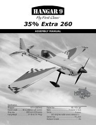
Section 16: Attaching the CowlingCONTINUEDStep 3. Use a Moto-tool and a carbide cutter to make thecylinder head and needle valve openings in the cowl.Note: For illustration purposes, we have shown anMDS 1.48 glow engine mounted in the <strong>Edge</strong> <strong>540</strong>.If you use a different engine, it will be necessary tomake the appropriate template and mark the cowl to fitthe engine you have.Step 4. Mount the engine in the aircraft. Slide the cowl onto thefuselage. Trial fit the cowl to the engine installed. Mount themuffler and trial fit again. Make sure the engine is mounted sothe prop drive hub is 6 1 /4'' from the firewall. This should providean approximate 3/16'' clearance between the cowl and thespinner backplate when mounted on the engine. Re-adjust thecowl or engine if necessary to obtain the proper clearance.Step 5. Tape the cowl securely in position and check to makesure it fits correctly. There should be ample clearance (1/8''around the engine and muffler). Make sure the prop hub iscentered in the opening in the cowl.Step 6. There will be two-button head hold-down screwslocated on either side of the cowl. With the cowl in position, thetop screw is located 1 1 /2'' from the edge of the cowl to the front,1/2'' down from the blue/yellow color line on the top of the cowl.The bottom screw is located directly below the top screw, 3 1 /4'' ata location 1 1 /2'' from the edge of the cowl and 3/8'' up from theyellow/blue color line at the bottom of the cowl.Step 7. Once the mounting holes have been marked, drill theholes on each side of the cowl using a 1/16'' drill bit. Be sure touse masking tape to hold the cowl securely in positionStep 8. Remove the cowling and enlarge the four holes in thecowling just enough to fit the rubber grommets in place.Note: On some engines where the carburetor is not easilyaccessible, a a fuel dot can be used. <strong>Hangar</strong> 9’s goldanodize machined aluminum fuel dot with “T” coupler(HAN115) is an excellent choice and should beavailable at your local hobby shop.Step 9. Align the cowling on the fuselage and secure it with thebutton head screws. Do not overtighten the screws by smashinginto the rubber grommets, as this will take away the vibrationisolation of the grommets.Step 10. Self-adhesive red trim tape is provided for trimmingthe cowl.38


