


Create successful ePaper yourself
Turn your PDF publications into a flip-book with our unique Google optimized e-Paper software.
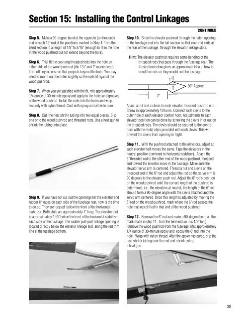
Section 15: Installing the Control LinkagesCONTINUEDStep 5. Make a 90-degree bend at the opposite (unthreaded)end of each 12'' rod at the positions marked in Step 4. Trim thebend section to a length of 1/8'' to 3/16'' (enough to fit in the holein the wood pushrod but not extend beyond the hole).Step 6. Trial fit the two long threaded rods into the hole oneither side of the wood pushrod (the 1 1 /2'' and 2'' marked end).Trim off any excess rod that projects beyond the hole. You mayneed to round out the holes slightly so the rods fit against thewood pushrod.Step 7. When you are satisfied with the fit, mix approximately1/4 ounce of 30-minute epoxy and apply to the holes and groovesof the wood pushrod. Install the rods into the holes and wrapsecurely with nylon thread. Coat with epoxy and allow to cure.Step 8. Cut the heat shrink tubing into two equal pieces. Slipone onto the wood pushrod and threaded rods. Use a heat gun toshrink the tubing into place.Step 9. If you have not cut out the openings for the elevator andrudder linkages on each side of the fuselage rear, now is the timeto do so. They are located below the front of the horizontalstabilizer. Both slots are approximately 1'' long. The elevator slotis approximately 1 3 /8'' below the front of the horizontal stabilizer,each side of the fuselage. The rudder pull-pull linkage opening islocated directly below the elevator linkage slot, along the red trimline at the fuselage bottom.Step 10. Slide the elevator pushrod through the hatch openingin the fuselage and into the tail section so that each rod exits atthe rear of the fuselage, through the elevator linkage slots.Hint: The elevator pushrod requires some bending of thethreaded rods that pass through the fuselage rear. Theillustration below gives an approximate idea of how tobend the rods so they would exit the fuselage.2''1''30° Approx.Attach a nut and a clevis to each elevator threaded pushrod end.Screw in approximately 10 turns. Connect each clevis to theouter hole of each elevator control horn. Adjustments to eachelevator position can be done by screwing the clevis in or out onthe threaded rods. The clevis should be secured to the controlhorn with the metal clips provided with each clevis. This willprevent the clevis from opening in flight.Step 11. With the pushrod attached to the elevators, adjust soeach elevator half moves the same. Tape the elevators in theneutral position (centered to horizontal stablizer). Attach the6'' threaded rod to the other end of the wood pushrod, threadedend toward the elevator servo in the fuselage. Make sure theelevator servo arm is centered. Thread a nut and clevis on thethreaded end of the 6'' rod and adjust the rod so the servo arm is90 degrees to the elevator push rod. Adjust the 6'' rod’s positionon the wood pushrod until the correct length of the pushrod isdetermined, i.e., the elevators at neutral, the length of the 6'' rodshould form a 90-degree angle with the clevis attached and theservo arm centered. Once this length is adjusted by moving the6'' rod on the wood pushrod, mark where the 6'' rod passes thehole that was drilled in that end of the wood pushrod.Step 12. Remove the 6'' rod and make a 90-degree bend at themark made in step 11. Trim the bent end so it is 1/8'' long.Remove the wood pushrod from the fuselage. Mix approximately1/4 ounce of 30-minute epoxy and epoxy the 6'' rod into thehole. Wrap with nylon thread. After the epoxy has cured, slip theheat shrink tubing over the rod and shrink usinga heat gun.35


