SHEAR PERFORMANCE OF STEEL FIBRE ... - SCNZ Magazine
SHEAR PERFORMANCE OF STEEL FIBRE ... - SCNZ Magazine
SHEAR PERFORMANCE OF STEEL FIBRE ... - SCNZ Magazine

You also want an ePaper? Increase the reach of your titles
YUMPU automatically turns print PDFs into web optimized ePapers that Google loves.
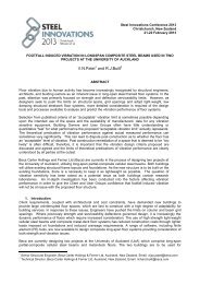
Steel Innovations Conference 2013Christchurch, New Zealand21-22 February 2013<strong>SHEAR</strong> <strong>PERFORMANCE</strong> <strong>OF</strong> <strong>STEEL</strong> <strong>FIBRE</strong>-REINFORCED CONCRETEA. Khanlou 1 , G. A. MacRae 2 , A. N. Scott 3 , S. J. Hicks 4 and G. C. Clifton 5ABSTRACTThis paper presents results from an experimental study and an analytical assessment on the shearperformance of steel fibre-reinforced concrete. Federation Internationale de la Precontrainte (FIP) standardshear tests were conducted on normal- and high-strength steel fibre-reinforced concrete (SFRC) specimens.Test parameters investigated include compressive strength of the concrete and fibre volume fraction. It wasfound that the steel fibres with a dosage of up to 80 kg/m 3 enhance the ultimate shear capacity of theconcrete up to 70 percent compared to plain concrete shear capacity. It was also observed that ultimateshear capacity of SFRC, with fibre dosage above 40 kg/m 3 , was higher than cracking shear stress. Anequation, based on regression analysis, is proposed to predict the shear capacity of the tested SFRC.IntroductionThe brittle and catastrophic shear failure of concrete can be mitigated by the addition of the steel fibres. Paststudies have shown that steel fibres can improve the shear performance of both normal-weight concrete andlight-weight concrete (Higashiyama and Banthia 2008; Majdzadeh et al. 2006; Mirsayah and Banthia 2002;Valle and Buyukozturk 1993; Narayanan and Darwish 1987).Among existing test methods for evaluating shear strength and shear toughness, which are the Z-type pushoffspecimen (Figure 1(a)), the Japanese Society of Civil Engineering (JSCE) standard method (JSCE-G553, 1999) (Figure 1(b)), and FIP standard (Figure 1(c)), the Z-type push-off specimen has been widely usedfor both traditionally reinforced concrete and SFRC. This is also known as Hoffbeck-style or double L-shapedspecimen. It is not a standardized test procedure, and different specimen sizes have been used in the paststudies. For instance, Hoffbeck et al. (1969) used specimens 546 mm high with a cross section of 254 mmby 127 mm, Walraven and Reinhardt (1981) used 600 mm high specimens with a cross section of 300 mmby 120 mm, Van de Look (1987) tested specimens with 600 mm height and a cross section of 400 mm by120 mm, Khaloo and Kim (1997) used 520 mm x 300 mm x 125 mm samples. Mirsayah and Banthia (2002)argued that in Hoffbeck-style push-off specimen, beyond cracking the stress conditions deviate significantlyfrom being in pure shear and the test does not simulate pure shear. Hence, Mirsayah and Banthia used theJSCE standard method (JSCE-G 553, 1999), which is a modified version of (JSCE-SF6, 1990), for theirtests. Moreover, Barragan et al. (2006) mentioned that using side grooves, and having reinforcing bars withinthe Hoffbeck-style push-off specimen could interface with fibre distribution. In addition, preparation ofHoffbeck-style push-off specimen is a cumbersome procedure if a large number of tests have to be carriedout.Since one of the aims of the current research is to investigate the effect of precracking on the shearperformance of the SFRC, using the JSCE standard (JSCE-G 553, 1999), which has two shear planes in itsspecimen, would not be practical. Because of the deficiencies and complexities of the aforementioned sheartest methods, it was decided to conduct the shear tests as per FIP standard. The size of the specimen in this1 Doctoral Candidate, Dept. of Civil and Natural Resources Engineering, University of Canterbury, Christchurch2 Associate Professor, Dept. of Civil and Natural Resources Engineering, University of Canterbury, Christchurch3 Lecturer, Dept. of Civil and Natural Resources Engineering, University of Canterbury, Christchurch4 General Manager, Structural Systems, Heavy Engineering Research Association (HERA), Manuka City, Auckland5 Associate Professor, Dept. of Civil and Environmental Engineering, University of Auckland, Auckland
method is 250 mm x 250 mm x 540 mm. In the FIP’s test method, the interface is theoretically subjected topure shear forces, and the occurrence of a bending moment owing to force eccentricities is minimized(Beushausen and Alexander 2007). Moreover, these test samples are easy to construct.VPShear SpecimenShear SpecimenShear planeV(a) Z-type push-off specimen (b) JSCE-G 553 shear test (c) FIP shear testFigure 1. Schematic of shear tests.Experimental ProgramThe purpose of the program was to study the shear performance of SFRC and to quantify the materialproperties of SFRC in shear. The considered variables were, concrete compressive strength and steel fibrevolume fraction.Materials and Concrete MixTo evaluate the effect of the concrete compressive strength, two reference concrete mix designs weredeveloped to achieve 35 MPa and 60 MPa after 28 days. The considered fibre dosages were 20, 40, 60, and80 kg/m 3 . One type of steel fibre, Dramix RC-80/60-BN, was used in the tests. The fibres were highstrength, hooked-end cold drawn produced by Bekaert. The dimensions and material properties of the steelfibres are given in Table 1. Locally available coarse aggregate (semi-crushed having maximum size of13mm) and fine aggregate (natural river sand) were used in all concrete mixes.Table 1. Properties of steel fibre.Lengthl f[mm]Diameterd f[mm]Aspect ratiol f / d fYield strengthσ fy[MPa]60 0.75 80 1050ShapeSince the inclusion of fibres significantly affect the workability properties of fresh concrete, rheological testinghas been carried out to achieve an optimum mix design for each dosage of fibre. Rheological tests wereconducted using the BML viscometer machine. As a result, eight mix designs were developed. Thecompositions of the mixes are summarized in Table 2. The mixture ID identifies the target compressivestrength of the concrete and fibre dosage. For example, C3540 represents a concrete mix with 35 MPatarget strength (C35), and 40 kg/m 3 steel fibre. From each mixture, three shear specimens and six 100 mmdiameterx 200 mm-long cylinders for compressive strength test (ASTM-C39, 1998) were cast. Threecylinders were tested at the age of 28 days, and the next three cylinders were tested at the day of testingshear specimens. Moreover, shear samples from C3520, C3540, C3580, C6020, C6040, and C6080 mixeswith no fibres added to the mix were taken to investigate the shear performance of the plain concrete mixes.These mixes are designated by C3520W, C3540W, C3580W, C6020W, C6040W, and C6080W.
Mixture IDTable 2. Mixture composition and properties of the concrete.FibreDosage[kg/m 3 ]Fibre volumefraction[%]w/cratioWaterCementCoarseaggregate[kg/m 3 ]Sand[kg/m 3 ] [kg/m 3 ][kg/m 3 ]C3520 20 0.25 0.6 172 287 1040 906C3540 40 0.51 0.6 175 292 920 1007C3560 60 0.76 0.6 185 308 750 1129C3580 80 1.0 0.6 190 317 600 1252C6020 20 0.25 0.4 172 410 1040 802C6040 40 0.51 0.4 175 417 920 901C6060 60 0.76 0.4 180 429 750 1041C6080 80 1.0 0.4 185 440 600 1161Shear TestsShear tests were conducted as per the FIP standard shear test. The schematic of the test setup and theinstrumentations is shown in Figure 2. Displacements in the direction of, and normal to, the shear plane weremeasured using linear variable differential transducers (LVDTs). The horizontal displacement (i.e. crackwidth) and the vertical displacement (i.e. crack slip) were computed as the average readings generatedbetween four and two LVDTs, respectively. In order to avoid cracking outside the intended failure shearplane a 15 mm deep and 3 mm notch was sawed all around the specimen. The tests were performed in aDARTEC universal testing machine with a capacity of 10000 kN. Initially loads were applied from 0 to 100 kNat a loading rate of 0.5 kN/s, subsequently the specimens were subjected to a continuously increasing sheardisplacement with a rate of 0.001 mm/s. Applied load and displacements were recorded at a frequency of10Hz.Figure 3(a) shows a picture of the shear test setup, andFigure 3(b) shows a fractured SFRC specimen.LVDT1LVDT4LVDT2LVDT5LVDT3LVDT6(a) West view(b) East viewFigure 2. Schematic of shear test setup and instrumentation.(a) Shear test setup(b) SFRC specimen after direct shear test
Shear stress (MPa)Shear stress (MPa)Shear stress (MPa)Shear stress (MPa)Figure 3. Photograph of the tests.Results and DiscussionThe typical stress-crack width displacement and stress-crack slip displacement for C35 and C60 SFRCshear specimens are shown in Figure 4 and Figure 5, respectively. Each curve is an average of three curvesobtained from shear tests on three shear specimens. Plain concrete specimens showed, as expected, asudden and brittle failure at a very low shear strain. The shear stress-displacement response is linear up tothe peak stress (i.e. cracking shear stress) and instantaneously the capacity to carry load beyond that pointis lost. On the other hand, failure in SFRC specimens is ductile. In C35 SFRC shear specimens with 20 and40 kg/m 3 of steel fibres, and in C60 SFRC shear specimens with 20 kg/m 3 of steel fibres the response up tothe cracking shear stress was followed by a gradually decreasing post-peak response. The cracking shearstress was the peak shear stress in these specimens (Figure 6). In C60 SFRC specimens with 40, 60, and80 kg/m 3 of steel fibres, and in C35 SFRC specimens with 60 and 80 kg/m 3 of steel fibres, however, there isan increase in post-peak load carrying capacity. In these specimens, as shown in Figure 6, the ultimateshear stress is higher than the cracking shear stress.1086480 kg/m 320 kg/m 3 40 kg/m 360 kg/m 3C35 Series1086480 kg/m 3C35 Series200 kg/m 3 00 0.5 1 1.5 2 2.5 3Crack width (mm)(a) Shear stress-crack width displacement240 kg/m 3 60 kg/m 320 kg/m 30 kg/m 30 0.5 1 1.5 2 2.5 3Crack slip (mm)(b) Shear stress-crack slip displacementFigure 4. C35 SFRC shear test curves.121086420kg/m 380 kg/m 360 kg/m 3C60 Series1210864C60 Series80 kg/m 360 kg/m 320 kg/m 3200 kg/m40 kg/m 30 0.5 1 1.5 2 2.5 3Crack width (mm)(a) Shear stress-crack width displacement200 kg/m 3 40 kg/m 30 0.5 1 1.5 2 2.5 3Crack slip (mm)(b) Shear stress-crack slip displacementFigure 5. C60 SFRC shear test curves.Ultimate shear stress and cracking shear stress of the plain concrete and SFRC specimens, along with thecompressive strength at 28days and on the shear test day are presented in Table 3. A plot of the test resultsis also shown in Figure 6. It can be seen that addition of steel fibres increased the cracking shear stress inSFRC specimens by 30%, compared to the plain concrete samples (designated with a ‘W’ in Table 3, and
Shear stress (MPa)Shear stress (MPa)shown by in Figure 6).plainTable 3. Compressive strength and shear test resultsMixtureIDf c ' .28day[MPa]f c ' .test day[MPa]τ crack [MPa] τ u[MPa]Increase in τ u[%]C3520 40.4 48.2 6.59 6.59 -C3520W 40.2 47.2 5.10 5.10 -C3540 40.0 46.9 6.95 6.95 -C3540W 42.1 48.6 5.28 5.28 -C3560 40.7 46.6 6.47 8.01 23C3580 38.7 46.6 6.52 8.64 32C3580W 36.8 45.8 4.70 4.70 -C6020 65.4 72.6 7.52 7.52 -C6020W 62.5 69.3 5.70 5.70 -C6040 63.0 69.6 7.65 8.54 11C6040W 64.4 71.3 6.20 6.20 -C6060 60.1 67.5 8.30 9.40 13C6080 65.3 72.5 7.90 10.2 30C6080W 60.4 68.1 6.40 6.40 -108642τ uCracking shear stressUltimate shear stressC35 seriesτ crackUltimate shear stress (mix without fibre)121042C60 seriesτ uτ crack8τ plain6τ plainCracking shear stressUltimate shear stressUltimate shear stress for mix without fibre00 0.2 0.4 0.6 0.8 1 1.2Fibre volume fraction (%)(a) C35 specimens00 0.2 0.4 0.6 0.8 1 1.2Fibre volume fraction (%)(b) C60 specimensFigure 6. Shear stress test results versus fibre volume fractionAn empirical shear transfer model, based on the regression analysis, has been developed to predict theultimate shear stress of SFRC for the particular models tested. The proposed strength prediction model is afunction of compressive strength of SFRC and its fibre volume fraction, and is expressed as (1)u' 0.90.75fc 4VfWheref is compressive strength of the SFRC cylinder in MPa, and'cas a percentage. In absence of fibres Equation (1) reduces toVfis fibre volume fraction expressed (2)u'0.75fcwhich is the shear strength of plain concrete. There is no globally accepted proportional constant value forthe interrelationship between the compressive strength and shear strength of concrete in the literature. Forinstance, Khaloo and Kim (1997), based on their test results, suggested that the ultimate shear strength of
Shear stress (MPa)plain concrete equals to'0.65c'find the correlation to be 0. 8'f , Mansur et al. (2008) proposed 0. 6150.56fc, Boulekbache et al. (2012)0.72fc. Mirsayah and Banthia (2002) did shear tests on concrete samples withcompressive strength of 47 MPa and obtained the shear strength of the plain concrete to be 7.5 MPa. Theycommented that this value is expected to depend indirectly on the compressive strength of concrete.The second term in Equation (1) expresses the additional shear resistance due to the presence of steelfibres.Figure 7 shows a comparison of the test results and the predictions of the proposed model for ultimate shearstrength of SFRC.121080.75√f c ' + 4V f0.96420C35 series - ExperimentalC60 series - Experimental0 0.2 0.4 0.6 0.8 1Fibre volume fraction (%)Figure 7. Comparison of test data of the present study and the proposed model for ultimate shear stress ofSFRC.ConclusionThe FIP shear test method was successfully used to obtain the shear performance of the SFRC and plainconcrete. The results demonstrate that the addition of steel fibres of as much as 20 kg/m 3 changes thefailure mode from brittle failure to a ductile failure. This means that the material can sustain significant loadsafter cracking. The improvements in shear strength of SFRC were more significant for steel fibre dosagesabove 40 kg/m 3 (0.5% fibre volume fraction), in both normal and high strength concrete. An empirical modelwas derived, based on regression analysis, to predict the shear strength of SFRC specimens.AcknowledgmentWe wish to acknowledge the Heavy Engineering Research Association for initiating this research projecttogether with the Heavy Engineering Education and Research Foundation for providing part of the financialsupport for the tests. Also, we wish to acknowledge MBIE Natural Hazards Research Platform, CompositeSolutions Grant. We also are grateful to Alan Ross from BOSFA (Bekaert OneSteel Fibres Australasia) forproviding the steel fibre. This paper is from the ASEC2012 Conference (Perth, Western Australia).ReferencesASTM. 1998. Standard test method for compressive strength of cylindrical concrete specimens. StandardASTM C39/CC39M-05, American Society for Testing and Materials (ASTM), West Conshohocken, Pa.Beushausen, H., & Alexander, M. 2008. Bond strength development between concretes of different ages.<strong>Magazine</strong> of Concrete Research, Vol 60(1) 65-74.Boulekbache, B., Hamrat, M., Chemrouk, M., & Amziane, S. 2012. Influence of yield stress and compressivestrength on direct shear behaviour of steel fibre-reinforced concrete. Construction and Building Materials. Vol27(1) 6-14.
Federation Internationale de la Precontrainte. 1978. Shear at the interface of precast and in-situ concrete.FIP, Lausanne. Technical report.Higashiyama, H., & Banthia, N. 2008. Correlating flexural and shear toughness of lightweight fiber-reinforcedconcrete. ACI Materials Journal, Vol 105(3) 251-257.Hoffbeck, J. A., Ibrahim, I. O. & Mattock, A. H. 1969. Shear transfer in reinforced concrete. Journal of theAmerican Concrete Institute, Vol 66(2) 119-128.JSCE. 1990. Method of test for shear strength of steel fiber reinforced concrete (SFRC). Standard JSCE-SF6, Japan Society of Civil engineers (JSCE), Tokyo.JSCE-G 553-1999. 2005. Test method for shear strength of steel fiber reinforced concrete. StandardSpecifications for Concrete Structures, Test Methods and Specifications, Japan Society of Civil engineers(JSCE), Tokyo.Khaloo, A. R., & Nakseok, K. 1997. Influence of concrete and fibre characteristics on behaviour of steel fiberreinforced concrete under direct shear. ACI Materials Journal, Vol 94(6) 596-601.Majdzadeh, F., Soleimani, S. M., & Banthia, N. 2006. Shear strength of reinforced concrete beams with afiber concrete matrix. Canadian Journal of Civil Engineering, Vol 33(6) 726-734.Mansur, M. A., Vinayagam, T., & Tan, K. H. 2008. Shear transfer across a crack in reinforced high-strengthconcrete. Journal of Materials in Civil Engineering (ASEC). Vol 20(4) 294-302.Mattock, A. H. 1974. Effect of aggregate type on single direction shear transfer strength in monolithicconcrete, Report SM 74-2, Department of Civil Engineering, University of Wshington, Seattle, Washington.Mattock, A. H., & Hawkins, N. M. 1972. Research on shear transfer in reinforced concerete.PCI Journal, Vol2(March/April) 55-75.Mirsayah, A. A., & Banthia, N. 2002. Shear strength of steel fiber-reinforced concrete. ACI Materials Journal,Vol 99(5) 473-479.Narayanan, R., & Darwish, I. Y. S. 1987. Use of steel fibers as shear reinforcement. ACI Structural Journal,Vol 84(3) 216-227.Swamy, R. N., Jones, R., & Chiam, A. T. D. 1987. Shear transfer in steel fiber reinforced concrete. ACISpecial Publication, SP105-29.Valle, M., & Buyukozturk, O. 1993. Behavior of fiber reinforced high-strength concrete under direct. ACIMaterials Journal, Vol 90(2) 122-133.Walraven, J. C., & Reinhardt, H. W. 1981. Theory and experiments on the mechanical behaviour of cracks inplain and reinforced concrete subjected to shear loading. HERON, Vol 26(1).